EP4501428A1 - Saugsieb - Google Patents
Saugsieb Download PDFInfo
- Publication number
- EP4501428A1 EP4501428A1 EP23780570.0A EP23780570A EP4501428A1 EP 4501428 A1 EP4501428 A1 EP 4501428A1 EP 23780570 A EP23780570 A EP 23780570A EP 4501428 A1 EP4501428 A1 EP 4501428A1
- Authority
- EP
- European Patent Office
- Prior art keywords
- section
- baffle plate
- suction strainer
- filtration section
- filtration
- Prior art date
- Legal status (The legal status is an assumption and is not a legal conclusion. Google has not performed a legal analysis and makes no representation as to the accuracy of the status listed.)
- Pending
Links
Images







Classifications
-
- B—PERFORMING OPERATIONS; TRANSPORTING
- B01—PHYSICAL OR CHEMICAL PROCESSES OR APPARATUS IN GENERAL
- B01D—SEPARATION
- B01D29/00—Filters with filtering elements stationary during filtration, e.g. pressure or suction filters, not covered by groups B01D24/00 - B01D27/00; Filtering elements therefor
- B01D29/11—Filters with filtering elements stationary during filtration, e.g. pressure or suction filters, not covered by groups B01D24/00 - B01D27/00; Filtering elements therefor with bag, cage, hose, tube, sleeve or like filtering elements
- B01D29/13—Supported filter elements
- B01D29/15—Supported filter elements arranged for inward flow filtration
- B01D29/21—Supported filter elements arranged for inward flow filtration with corrugated, folded or wound sheets
-
- B—PERFORMING OPERATIONS; TRANSPORTING
- B01—PHYSICAL OR CHEMICAL PROCESSES OR APPARATUS IN GENERAL
- B01D—SEPARATION
- B01D24/00—Filters comprising loose filtering material, i.e. filtering material without any binder between the individual particles or fibres thereof
-
- B—PERFORMING OPERATIONS; TRANSPORTING
- B01—PHYSICAL OR CHEMICAL PROCESSES OR APPARATUS IN GENERAL
- B01D—SEPARATION
- B01D29/00—Filters with filtering elements stationary during filtration, e.g. pressure or suction filters, not covered by groups B01D24/00 - B01D27/00; Filtering elements therefor
-
- B—PERFORMING OPERATIONS; TRANSPORTING
- B01—PHYSICAL OR CHEMICAL PROCESSES OR APPARATUS IN GENERAL
- B01D—SEPARATION
- B01D29/00—Filters with filtering elements stationary during filtration, e.g. pressure or suction filters, not covered by groups B01D24/00 - B01D27/00; Filtering elements therefor
- B01D29/01—Filters with filtering elements stationary during filtration, e.g. pressure or suction filters, not covered by groups B01D24/00 - B01D27/00; Filtering elements therefor with flat filtering elements
- B01D29/05—Filters with filtering elements stationary during filtration, e.g. pressure or suction filters, not covered by groups B01D24/00 - B01D27/00; Filtering elements therefor with flat filtering elements supported
- B01D29/07—Filters with filtering elements stationary during filtration, e.g. pressure or suction filters, not covered by groups B01D24/00 - B01D27/00; Filtering elements therefor with flat filtering elements supported with corrugated, folded or wound filtering sheets
-
- B—PERFORMING OPERATIONS; TRANSPORTING
- B01—PHYSICAL OR CHEMICAL PROCESSES OR APPARATUS IN GENERAL
- B01D—SEPARATION
- B01D29/00—Filters with filtering elements stationary during filtration, e.g. pressure or suction filters, not covered by groups B01D24/00 - B01D27/00; Filtering elements therefor
- B01D29/50—Filters with filtering elements stationary during filtration, e.g. pressure or suction filters, not covered by groups B01D24/00 - B01D27/00; Filtering elements therefor with multiple filtering elements, characterised by their mutual disposition
- B01D29/56—Filters with filtering elements stationary during filtration, e.g. pressure or suction filters, not covered by groups B01D24/00 - B01D27/00; Filtering elements therefor with multiple filtering elements, characterised by their mutual disposition in series connection
- B01D29/58—Filters with filtering elements stationary during filtration, e.g. pressure or suction filters, not covered by groups B01D24/00 - B01D27/00; Filtering elements therefor with multiple filtering elements, characterised by their mutual disposition in series connection arranged concentrically or coaxially
-
- B—PERFORMING OPERATIONS; TRANSPORTING
- B01—PHYSICAL OR CHEMICAL PROCESSES OR APPARATUS IN GENERAL
- B01D—SEPARATION
- B01D35/00—Filtering devices having features not specifically covered by groups B01D24/00 - B01D33/00, or for applications not specifically covered by groups B01D24/00 - B01D33/00; Auxiliary devices for filtration; Filter housing constructions
- B01D35/02—Filters adapted for location in special places, e.g. pipe-lines, pumps, stop-cocks
- B01D35/027—Filters adapted for location in special places, e.g. pipe-lines, pumps, stop-cocks rigidly mounted in or on tanks or reservoirs
-
- B—PERFORMING OPERATIONS; TRANSPORTING
- B01—PHYSICAL OR CHEMICAL PROCESSES OR APPARATUS IN GENERAL
- B01D—SEPARATION
- B01D35/00—Filtering devices having features not specifically covered by groups B01D24/00 - B01D33/00, or for applications not specifically covered by groups B01D24/00 - B01D33/00; Auxiliary devices for filtration; Filter housing constructions
- B01D35/02—Filters adapted for location in special places, e.g. pipe-lines, pumps, stop-cocks
- B01D35/027—Filters adapted for location in special places, e.g. pipe-lines, pumps, stop-cocks rigidly mounted in or on tanks or reservoirs
- B01D35/0273—Filtering elements with a horizontal or inclined rotation or symmetry axis submerged in tanks or reservoirs
-
- B—PERFORMING OPERATIONS; TRANSPORTING
- B01—PHYSICAL OR CHEMICAL PROCESSES OR APPARATUS IN GENERAL
- B01D—SEPARATION
- B01D36/00—Filter circuits or combinations of filters with other separating devices
- B01D36/001—Filters in combination with devices for the removal of gas, air purge systems
-
- B—PERFORMING OPERATIONS; TRANSPORTING
- B01—PHYSICAL OR CHEMICAL PROCESSES OR APPARATUS IN GENERAL
- B01D—SEPARATION
- B01D2201/00—Details relating to filtering apparatus
- B01D2201/20—Pressure-related systems for filters
- B01D2201/204—Systems for applying vacuum to filters
-
- B—PERFORMING OPERATIONS; TRANSPORTING
- B01—PHYSICAL OR CHEMICAL PROCESSES OR APPARATUS IN GENERAL
- B01D—SEPARATION
- B01D2201/00—Details relating to filtering apparatus
- B01D2201/29—Filter cartridge constructions
- B01D2201/291—End caps
- B01D2201/298—End caps common to at least two filtering elements
-
- B—PERFORMING OPERATIONS; TRANSPORTING
- B01—PHYSICAL OR CHEMICAL PROCESSES OR APPARATUS IN GENERAL
- B01D—SEPARATION
- B01D2201/00—Details relating to filtering apparatus
- B01D2201/30—Filter housing constructions
- B01D2201/301—Details of removable closures, lids, caps, filter heads
Definitions
- the present invention relates to a suction strainer.
- PTL 1 discloses a suction filter provided with a cover and a valve.
- the cover is provided at the upper end surface of a cylindrical first filtration section so as to cover the entirety of the upper side of the first filtration section, and the valve is provided at a hollow part of the first filtration section on the lower side of the cover.
- a first valve that is movable along a bar-shaped member is switched between a closed state of closing a hole of the cover and an open state of not closing the hole.
- FIG. 15 is views schematically illustrating behavior of bubbles adhering to a filtration section 150, where (A) is an example of vertical placement and (B) is an example of horizontal placement.
- the bubbles adhering to the filtration section 150 float upward along the filtration section 150 (see arrows in FIG. 15(A) ).
- the bubbles adhering to the upper half of the filtration section 150 can float upward (see arrows in FIG. 15(B) ), but the bubbles adhering to the lower half of the filtration section 150 are blocked by the filtration section 150 and cannot float upward.
- the present invention has been made in view of such circumstances, and an object is to provide a suction strainer that can prevent bubbles from flowing out when a filtration section is provided along a horizontal direction.
- a suction strainer is, for example, a suction strainer provided in a tank in which liquid is stored, the suction strainer including: a filtration section having a cylindrical shape including a pleated filter having a cylindrical shape formed by bending a thin plate into a pleated shape; an attachment section having a cylindrical shape provided on a side surface of the tank, the attachment section provided with one end of the filtration section; a plate covering an end of the filtration section on a side not provided with the attachment section; and a baffle plate including at least one of a first baffle plate provided inside the pleated filter and a second baffle plate provided outside the pleated filter, in which the filtration section is provided along a horizontal direction, the filtration section and the plate are provided inside the tank, at least a part of the first baffle plate is disposed above a central axis of the filtration section, and at least a part of the second baffle plate is disposed below the central axis.
- the filtration section provided along the horizontal direction and the plate covering one end of the filtration section are provided inside the tank in which the liquid is stored.
- the suction strainer includes at least one of the first baffle plate provided inside the pleated filter included in the filtration section and the second baffle plate provided outside the pleated filter, at least a part of the first baffle plate is disposed above the central axis of the filtration section, and at least a part of the second baffle plate is disposed below the central axis of the filtration section.
- the first baffle plate may include an air reservoir section having a cylindrical shape with one end provided in the attachment section, and a radius of the air reservoir section may gradually decrease along the direction from the attachment section toward the plate. This applies an upward force to the bubbles in contact with the air reservoir section, and the bubbles are less likely to flow into the hollow portion of the attachment section.
- the air reservoir section has a cylindrical shape, more bubbles can be blocked by the air reservoir section.
- the first baffle plate may have a cross-sectional shape that is an arc shape when taken along a first plane orthogonal to the central axis, and include an air reservoir section intersecting a line segment connecting an upper end portion of the filtration section and the central axis, the air reservoir section may have one end provided in the attachment section, and a radius of the air reservoir section may gradually decrease along a direction from the attachment section toward the plate. This applies an upward force to the bubbles in contact with the air reservoir section, and the bubbles are less likely to flow into the hollow portion of the attachment section.
- the first baffle plate may include an upper cover having a cross-sectional shape that is an arc shape when taken along a first plane orthogonal to the central axis, and provided at a position intersecting a line segment connecting an upper end portion of the filtration section and the central axis, and the upper cover may be provided on the plate side relative to the air reservoir section. This allows more bubbles to be stored in a space above the air reservoir section, and as a result, bubbles flowing out of the suction strainer can be further reduced.
- the second baffle plate may be a lower cover having a cross-sectional shape that is an arc shape when taken along a first plane orthogonal to the central axis, and provided at a position intersecting a line segment connecting a lower end portion of the filtration section and the central axis. This blocks the bubbles by the lower cover, and the bubbles hardly flow into the hollow portion of the filtration section.
- the pleated filter may include a first pleated filter having a cylindrical shape and a second pleated filter having a cylindrical shape provided inside the first pleated filter, the first baffle plate may be provided inside the second pleated filter, and the second baffle plate may be provided outside the second pleated filter. This can prevent outflow of bubbles from the suction strainer also in a case of including two pleated filters.
- the attachment section may be provided with an air vent hole allowing a hollow portion of the attachment section and an external space of the attachment section to communicate with each other, and the air vent hole may accommodates a float movable between a position where the float closes the air vent hole and a position where the float opens the air vent hole. This can discharge bubbles through the air vent hole.
- a cover having a cylindrical shape with one end provided on the attachment section and another end provided on the plate may be included, the cover may be provided along a horizontal direction, and a plurality of holes may be provided in a belt-shaped region along a horizontal direction positioned in a vicinity of a lower end of the cover. This can reduce the number of bubbles hitting the filtration section.
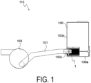
- FIG. 1 is a schematic diagram illustrating a hydraulic circuit 110 including a suction strainer 1 according to an embodiment of the present invention.
- FIG. 1 hatching indicating a cross section is omitted.
- the tank 100 is installed in a work machine (e.g., a hydraulic apparatus) not illustrated in the drawing.
- the tank 100 is a tank for storing the hydraulic fluid and is provided in a hydraulic circuit 110 of the hydraulic fluid to be supplied to the hydraulic apparatus.
- the component provided in the tank 100 is not limited to the hydraulic circuit, and the liquid stored in the tank 100 is also not limited to the hydraulic fluid.
- the tank 100 has a box shape that is hollow inside, for example.
- the tank 100 mainly includes inside the suction strainer 1 and a return filter (omitted in the drawing).
- the hydraulic fluid is introduced to the tank 100 through a hydraulic apparatus not illustrated in the drawing.
- a hydraulic apparatus not illustrated in the drawing.
- an inlet (omitted in the drawing) that allows the hydraulic fluid to flow into the tank 100 is formed.
- the hydraulic fluid having entered from the inlet is guided to the return filter.
- the hydraulic fluid is filtered by the return filter, and stored in the tank 100.
- an outlet 100c that allows the hydraulic fluid inside the tank 100 to flow out to a hydraulic pump 103 is formed.
- the outlet 100c is provided with the suction strainer 1.
- the suction strainer 1 has a cylindrical shape and is provided along the horizontal direction.
- the suction strainer 1 is provided with a suction pipe 101 extending from the outer side of the tank 100 to the suction port of the hydraulic pump 103.
- the hydraulic fluid stored in the tank 100 is suctioned by the hydraulic pump 103, carried to the suction pipe 101 through the suction strainer 1, and supplied to the hydraulic apparatus again.
- outlet 100c and the suction strainer 1 need only to be provided at the side surface 100b of the tank 100, and the positions of the outlet 100c and the suction strainer 1 are not limited to the positions illustrated in FIG. 1 .
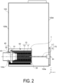
- FIG. 2 is a schematic diagram illustrating the suction strainer 1 and a tank 100.
- the extending direction of the suction strainer 1 (the extending direction of a central axis ax of the suction strainer 1) is the x direction
- the vertical direction is the z direction (vertically upward is the +z direction).
- the direction orthogonal to the x direction and the z direction is the y direction.
- the suction strainer 1 mainly includes a filtration section 10, an attachment section 20, a plate 30, a cover 40, floats 51 and 52, a baffle plate 61, and an attachment section 70.
- the attachment section 20 is provided on a side surface 100b of the tank 100
- the attachment section 70 is provided on a side surface 100d of the tank 100.
- the attachment section 70 includes a plate-shaped portion 71 and a bar-shaped member 72.
- the plate-shaped portion 71 is attached to the side surface 100d, the plate 30 attached to the bar-shaped member 72 is pushed in a -x direction, whereby the suction strainer 1 is provided inside the tank 100.
- the filtration section 10 mainly includes pleated filters 11 and 12 and inner cylinders 13 and 14.
- the inner cylinders 13 and 14 are provided inside the pleated filters 11 and 12, respectively.
- the pleated filters 11 and 12 are members that filter a hydraulic fluid, and have a cylindrical shape (here, a circular cylindrical shape). The heights of the pleated filters 11 and 12 are substantially the same.
- the pleated filters 11 and 12 are formed by pleating a sheet-like thin plate having holes formed in substantially the entire area, connecting both ends of the pleated thin plate, and rounding the pleated thin plate into a cylindrical shape. Thus, the pleated filters 11 and 12 are formed in a substantially circular cylindrical pleated shape.
- the pleated filter 12 is formed of a wire mesh made of fine metal (e.g., stainless steel) in which thin wires are knitted in a mesh shape, but filter paper using synthetic resin, paper, or the like may be used.
- the diameter of the pleated filter 12 (corresponding to the second pleated filter of the present invention) is smaller than the diameter of the pleated filter 11 (corresponding to the first pleated filter of the present invention), and the pleated filter 12 is provided inside the pleated filter 11.
- the inner cylinders 13 and 14 are members having a cylindrical shape (here, a circular cylindrical shape) having openings at both ends, and are formed using a material having high corrosion resistance (e.g., stainless steel).
- the heights of the inner cylinders 13 and 14 are substantially the same as the heights of the pleated filters 11 and 12.
- the diameter of the inner cylinder 13 is smaller than a diameter of the pleated filter 11, and the inner cylinder 13 is provided inside the pleated filter 11.
- the diameter of the inner cylinder 14 is smaller than the diameter of the pleated filter 12, and the inner cylinder 14 is provided inside the pleated filter 12.
- Holes 13a and 14a through which the hydraulic fluid passes are formed substantially entirely in the inner cylinders 13 and 14.
- the hydraulic fluid having passed through the pleated filter 11 passes through the hole 13a and flows into the inner cylinder 13.
- the hydraulic fluid flowing into the inner cylinder 13 passes through the pleated filter 12, passes through the hole 14a, and flows into the inner cylinder 14.
- the first attachment section 21 has a cylindrical portion 21a to be inserted into the outlet 100c and a flange portion 21b abutting on the side surface 100b. A part of the cylindrical portion 21a and the flange portion 21b are provided outside the tank 100.
- the second attachment section 22 is provided in the first attachment section 21, and includes a cylindrical portion 22a into which the cylindrical portion 21a is inserted, and a plate-shaped portion 22b provided with the filtration section 10.
- the second attachment section 22 is provided inside the tank 100.
- the plate-shaped portion 71 (not illustrated in FIG. 3 ) is attached to the side surface 100d
- the plate 30, that is, the second attachment section 22 is pushed in the -x direction by the bar-shaped member 72.
- the cylindrical portion 21a is inserted into the cylindrical portion 22a, and an elastic member 55 (e.g., an O-ring) is provided between the cylindrical portion 21a and the cylindrical portion 22a, thereby integrating a hollow portion 21c of the cylindrical portion 21a and a hollow portion 22e of the cylindrical portion 22a.
- the hollow portion of the attachment section 20, that is, the hollow portion 21c and the hollow portion 22e allow a hollow portion (space S3) of the filtration section 10 and the outside of the tank 100 (the inside of the suction pipe 101) to communicate with each other.
- the plate-shaped portion 22b has recess portions 22c and 22d.
- the recess portion 22c is provided with the pleated filter 11 and the inner cylinder 13, and the recess portion 22d is provided with the pleated filter 12 and the inner cylinder 14. Due to this, the attachment section 20 is provided with the filtration section 10, and the filtration section 10 is extended along the horizontal direction.
- the plate-shaped portion 22b is provided with an air vent hole 22f.
- the air vent hole 22f is provided at a vertically upper end of the plate-shaped portion 22b.
- the air vent hole 22f allows the hollow portion 22e and an external space (here, space S1) of attachment section 20 to communicate with each other.
- space S1 is a space between the filtration section 10 and the attachment section 20, and the cover 40.
- the float 51 is provided at an upper end of the air vent hole 22f.
- the float 51 is movable in an up-down direction (z direction) between a position where the float 51 closes the air vent hole 22f and a position where the float 51 opens the air vent hole 22f.
- z direction a position where the float 51 closes the air vent hole 22f
- the air vent hole 22f is opened. This can discharge the air stored in the hollow portion of the attachment section 20 and the suction pipe 101 to the space S1 via the air vent hole 22f.
- the cover 40 is a cylindrical member and is extended along the horizontal direction. A belt-shaped region along the horizontal direction positioned in a vicinity of a lower end of the cover 40 is provided with a plurality of holes 40a. Note that the cover 40 is not essential.
- the cover 40 has one end provided on the side surface 100b, and the other end provided on the plate 30. That is, the plate 30 covers ends (openings) of the filtration section 10 and the cover 40. Due to this, the hydraulic fluid flows into the space S1 from the hole 40a and flows into a space S2 and the space S3 from the filtration section 10.
- the space S2 is a space between the pleated filter 11 and the pleated filter 12.
- the cover 40 is provided with a hole not illustrated, and this hole is provided with a float 52.
- the float 52 is movable in the up-down direction (z direction) between a position where the float 52 closes the hole and a position where the float 52 opens the hole.
- the baffle plate 61 (corresponding to the first baffle plate of the present invention) is provided inside the filtration section 10.
- the baffle plate 61 has a cylindrical shape as a whole, and has one end provided in the attachment section 20.
- the baffle plate 61 mainly includes an air reservoir section 61a having a cylindrical shape and an extension cylinder 61b having a cylindrical shape provided in the air reservoir section 61a.
- the radius of the air reservoir section 61a is large on the attachment section 20 side, and the radius gradually decreases toward the plate 30.
- the radius of the extension cylinder 61b is the same as the minimum radius of the air reservoir section 61a. Note that the extension cylinder 61b is not essential.
- the attachment section 20 is provided at one end of the filtration section 10 and the plate 30 is provided at the other end, when suctioned by the hydraulic pump 103 (not illustrated in FIG. 3 ) as indicated by hollow arrow in FIG. 3 , the hydraulic fluid stored in the tank 100 is suctioned into the space S1 from the outside of the cover 40 through the hole 40a, is suctioned into the space S2 from the space S1 through the pleated filter 11 and the inner cylinder 13, is suctioned into the space S3 from the space S2 through the pleated filter 12 and the inner cylinder 14, and flows out from the space S3 to the suction pipe 101 through the hollow portion 21c and the hollow portion 22e.
- the bubbles V1 flowing into the space S3 can be prevented from flowing out from the suction strainer 1 provided along the horizontal direction by retaining the bubbles V2 in the space S3 by the baffle plate 61.
- accumulation of bubbles in the suction pipe 101 and defects due to the pump suctioning the air can be prevented.
- damage of a component and the like resulting from the air bubbles bursting inside the hydraulic circuit or the like, which causes a temperature and a pressure of the hydraulic fluid to temporarily increase to a significant degree can be prevented.
- the air reservoir section 61a having a radius large on the attachment section 20 side, and the radius gradually decreases toward the plate 30 is included, an upward force is applied to the bubbles V2 abutting on the air reservoir section 61a, and the bubbles V2 are less likely to flow into the hollow portion of the attachment section 20.
- the bubbles can be discharged through the air vent hole 22f.
- the baffle plate 61 since the baffle plate 61 has a cylindrical shape, even if the bubbles V1 flow in the -x direction before floating in the +z direction, the bubbles V1 are blocked by the baffle plate 61, and the bubbles V2 can be formed on the upper side of the baffle plate 61. Therefore, outflow of bubbles from the suction strainer 1 can be prevented.
- the cover 40 in which the plurality of holes 40a are formed is provided in the belt-shaped region along the horizontal direction positioned in the vicinity of the lower end, the bubbles formed when flowing into the tank from the return filter hardly hit the filtration section 10. This reduces the number of bubbles V1 hitting the filtration section 10, and can reduce inflow of the bubbles V1 into the space S3.
- FIG. 4 is a schematic diagram illustrating a suction strainer 1A having a baffle plate 61A having a semicircular shape in cross-sectional view. Note that FIG. 4 partially omits hatching indicating a cross section.
- the difference between the suction strainer 1A and the suction strainer 1 is only the baffle plate 61A.
- the baffle plate 61A (corresponding to the first baffle plate of the present invention) is provided inside the filtration section 10.
- the baffle plate 61A has a semicircular shape in cross-sectional view when taken along a plane (plane parallel to a yz plane, corresponding to the first plane of the present invention) orthogonal to the central axis ax. That is, the baffle plate 61A may be disposed at least above the central axis ax of the filtration section 10, and a part of the baffle plate 61A may be disposed at the same height as the central axis ax or may be disposed below the central axis ax.
- the baffle plate 61A includes an air reservoir section 61c and an extension portion 61d provided in the air reservoir section 61c.
- the air reservoir section 61c is a half on the +z side of the air reservoir section 61a, and is inclined such that the radius is large on the attachment section 20 side and the radius gradually decreases toward the plate 30.
- the extension portion 61d is a half on the +z-side of the extension cylinder 61b.
- the radius of the extension portion 61d is the same as the minimum radius of the air reservoir section 61a.
- the air reservoir section 61c and the extension portion 61d intersect a line segment connecting the upper end portion of the filtration section 10 and the central axis ax. Note that the extension portion 61d is not essential.
- the cross-sectional shape of the baffle plate 61A when taken along a plane orthogonal to the central axis ax is not limited to a semicircular shape, and may be an arc shape. That is, the baffle plate 61A may be a part on the +z side of the baffle plate 61, and the baffle plate 61A may intersect the line segment connecting the upper end portion of the filtration section 10 and the central axis ax.
- the filtration section 10 includes the two pleated filters 11 and 12, but the number of pleated filters included in the filtration section 10 is not limited to this.
- the second embodiment of the present invention is a form in which the filtration section includes one pleated filter.
- description is given of a suction strainer 2 according to the second embodiment. Note that the same components as those in the first embodiment are denoted by the same reference numerals, and descriptions thereof will be omitted.
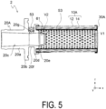
- FIG. 5 is a cross-sectional view schematically illustrating a suction strainer 2.
- hatching for indicating a cross section is omitted.
- the suction strainer 2 mainly includes a filtration section 10A, an attachment section 20A, a plate 30A, a float 53, and the baffle plate 61.
- the attachment section 20A is provided on the side surface 100b (not illustrated in FIG. 5 ) of the tank 100 (not illustrated in FIG. 5 ).
- the filtration section 10A includes the pleated filter 12 and the inner cylinder 14.
- the attachment section 20A is provided at one end (-z side) of the filtration section 10A, and the plate 30A is provided at the other end (+z side).
- the attachment section 20A and the plate 30A cover the ends of the filtration section 10A, respectively.
- the attachment section 20A mainly includes a cylindrical portion 20a into which the suction pipe 101 (not illustrated in FIG. 5 ) is inserted, a flange portion 20b abutting on the side surface 100b, an attachment section 20d attached with the filtration section 10A, and a cylindrical portion 20f between the flange portion 20b and the attachment section 20d.
- the cylindrical portion 20f is inserted into the outlet 100c, and the attachment section 20d is provided inside the tank 100.
- the attachment section 20d includes a recess portion 20e into which the filtration section 10A is inserted.
- the filtration section 10A is provided in the tank 100 along the horizontal direction (here, x direction).
- the cylindrical portion 20a is provided with an air vent hole 20g.
- the air vent hole 20g is provided at a vertically upper end of the cylindrical portion 20a.
- the air vent hole 20g allows a hollow portion 20c of the cylindrical portion 20a and an external space of cylindrical portion 20a to communicate with each other.
- the float 53 is provided at an upper end of the air vent hole 20g.
- the float 53 is movable in the up-down direction (z direction) between a position where the float 53 closes the air vent hole 20g and a position where the float 53 opens the air vent hole 20g.
- z direction the up-down direction
- the air vent hole 20g is opened. This can discharge, to the outside of the attachment section 20A via the air vent hole 20g, the air stored in the hollow portion of the attachment section 20 and the suction pipe 101.
- the baffle plate 61 is disposed inside the filtration section 10A. One end of the baffle plate 61 is provided in the attachment section 20A.
- the attachment section 20A is provided at one end of the filtration section 10A and the plate 30A is provided at the other end, when suctioned by the hydraulic pump 103 (not illustrated in FIG. 5 ), the hydraulic fluid stored in the tank 100 is suctioned into the space S3 through the pleated filter 12 and the inner cylinder 14, and flows out from the space S3 to the suction pipe 101 through the hollow portion 20c. Since the hydraulic fluid is sucked by the hydraulic pump 103, the float 53 is pulled in the -z direction together with the hydraulic fluid, and the float 53 closes the air vent hole 20g. Due to this, the hydraulic fluid does not flow into the space S3 from portions other than the filtration section 10A.
- the bubbles V1 contained in the hydraulic fluid are also suctioned into the filtration section 10 together with the hydraulic fluid.
- the bubbles V1 flow in the +z direction and the -x direction along the flow of the hydraulic fluid and abut on the baffle plate 61.
- the bubbles V1 accumulate in a space above (+z side) the baffle plate 61, and grow into the large bubbles V2. Due to this, the bubbles V2 hardly flow out to the hollow portion 20c.
- the bubbles V1 flowing into the space S3 can be prevented from flowing out from the suction strainer 2 provided along the horizontal direction by retaining the bubbles V2 in the space S3 by the baffle plate 61.
- the baffle plate 61 includes the air reservoir section 61a and the extension cylinder 61b, but the form of the baffle plate is not limited to this.
- the third embodiment of the present invention is a form in which the baffle plate includes an upper cover. A suction strainer 3 according to the third embodiment will be described below. Note that the same components as those in the first embodiment are denoted by the same reference numerals, and descriptions thereof will be omitted.
- FIG. 6 is schematic diagrams illustrating a suction strainer 3, where (A) is a cross-sectional view and (B) is a cross-sectional view of the suction strainer 3 taken along plane A-A.
- FIG. 6 partially omits hatching indicating a cross section.
- the suction strainer 3 mainly includes the filtration section 10, the attachment section 20, the plate 30, the cover 40, the floats 51 and 52, a baffle plate 61B, and the attachment section 70 (partially not illustrated in FIG. 6 ).
- the baffle plate 61B (corresponding to the first baffle plate of the present invention) is provided inside the filtration section 10.
- the baffle plate 61B has one end provided in the attachment section 20.
- the baffle plate 61B mainly includes the air reservoir section 61a having a cylindrical shape, the extension cylinder 61b having a cylindrical shape, and an upper cover 61e.
- the upper cover 61e is provided on the plate 30 more than the air reservoir section 61a.
- one end of the upper cover 61e is provided in the extension cylinder 61b, but when the extension cylinder 61b is not provided, the upper cover 61e may be provided in the air reservoir section 61a.
- the upper cover 61e has a cross-sectional shape that is an arc shape when taken along a plane (A-A cross section) orthogonal to the central axis ax.
- a central angle ⁇ 1 of the upper cover 61e is approximately 90 degrees in the A-A cross section.
- the upper cover 61e is provided at a position intersecting a line segment connecting the upper end portion of the filtration section 10 and the central axis ax when taken along a plane (A-A cross section) orthogonal to the central axis ax.
- the suction strainer 3 similarly to the suction strainer 1, when suctioned by the hydraulic pump 103 (not illustrated in FIG. 6 ), the hydraulic fluid stored in the tank 100 is suctioned into the space S3 from the outside of the cover 40 via the hole 40a and the filtration section 10, and flows out from the space S3 to the suction pipe 101 via the hollow portion 21c and the hollow portion 22e.
- the floats 51 and 52 are pulled in the -z direction together with the hydraulic fluid, the float 51 closes the air vent hole 22f, and the float 52 closes the hole of the cover 40. Due to this, the hydraulic fluid does not flow into the space S3 from portions other than the hole 40a and the filtration section 10.
- the bubbles V1 contained in the hydraulic fluid are also suctioned into the space S3 together with the hydraulic fluid.
- the bubbles V1 flowing into the space S3 from below the filtration section 10 flow in the +z direction and the -x direction along the flow of the hydraulic fluid, and abut on the air reservoir section 61a.
- the bubbles V2 accumulated above the baffle plate 61B are discharged to the space S1 via the filtration section 10 when the hydraulic pump 103 (not illustrated in FIG. 6 ) stops.
- the bubbles V2 are discharged in the space S1, grow, and push up the float 52 in the +z direction, the holes of the cover 40 are opened, and air is released from the space S1 to the outside of the suction strainer 3.
- the bubbles V1 flowing into the space S3 can be prevented from flowing out from the suction strainer 3 provided along the horizontal direction by retaining the bubbles V2 in the space S3 by the baffle plate 61B.
- the baffle plate 61B By providing the upper cover 61e, more bubbles V1 can be stored in the space above the air reservoir section 61a, and as a result, bubbles flowing out from the suction strainer 3 can be further reduced.
- FIG. 7 is schematic diagrams illustrating a suction strainer 3A having a baffle plate 61C according to a modification, where (A) is a cross-sectional view and (B) is a cross-sectional view of the suction strainer 3A taken along plane B-B. Note that FIG. 7 partially omits hatching indicating a cross section.
- the baffle plate 61C (corresponding to the first baffle plate of the present invention) mainly includes the air reservoir section 61a having a cylindrical shape, the extension cylinder 61b having a cylindrical shape, and an upper cover 61f.
- the upper cover 61f is provided on the plate 30 more than the air reservoir section 61a.
- the difference between the upper cover 61f and the upper cover 60c is a central angle.
- a central angle ⁇ 2 of the upper cover 61f is approximately 120 degrees.
- the central angle of the upper cover is not limited to 90 degrees or 120 degrees.
- the upper cover may be provided so as to intersect a line segment connecting the upper end portion of the filtration section 10 and the central axis ax.
- the baffle plate 61B includes the air reservoir section 61a, the extension cylinder 61b, and the upper cover 61e, but the form of the baffle plate is not limited to this.
- FIG. 8 is a cross-sectional view schematically illustrating a suction strainer 4.
- FIG. 8 partially omits hatching indicating a cross section.
- the suction strainer 4 mainly includes the filtration section 10, the attachment section 20, the plate 30, the cover 40, the floats 51 and 52, a baffle plate 61D, and the attachment section 70 (partially not illustrated in FIG. 8 ).
- the baffle plate 61D (corresponding to the first baffle plate of the present invention) is provided inside the filtration section 10.
- the baffle plate 61D has one end provided in the attachment section 20.
- the baffle plate 61D mainly includes the air reservoir section 61a having a cylindrical shape and an extension cylinder 61h having a cylindrical shape.
- the extension cylinder 61h is provided on the plate 30 more than the air reservoir section 61a.
- the extension cylinder 61h has a band-shaped region 61i provided with a large number of holes 61j.
- the band-shaped region 61i is provided in a band shape along the x direction below (-z side) the extension cylinder 61h.
- the -x side of the band-shaped region 61i is a cylindrical portion 61g, and the +z side of the band-shaped region 61i is an upper cover 61k.
- the upper cover 61k has a cross-sectional shape that is an arc shape when taken along a plane orthogonal to the central axis ax.
- the upper cover 61k is provided at a position intersecting a line segment connecting the upper end portion of the filtration section 10 and the central axis ax when taken along a plane orthogonal to the central axis ax.
- the position and shape of the band-shaped region 61i are not limited to this.
- the cylindrical portion 61g is not essential.
- the central angle of the upper cover 61k is 120 degrees, the central angle is not limited to this.
- the bubbles V1 flowing into the space S3 can be prevented from flowing out from the suction strainer 4 provided along the horizontal direction by retaining the bubbles V2 in the space S3 by the baffle plate 61D.
- the baffle plate 61D By providing the upper cover 61k, bubbles flowing out of the suction strainer 4 can be further reduced.
- the baffle plate 61 is provided inside the filtration section 10, but the form of the baffle plate is not limited to this.
- a baffle plate is provided outside the pleated filter 12.
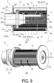
- FIG. 9 is schematic diagrams illustrating a suction strainer 5, where (A) is a cross-sectional view and (B) is a perspective view.
- FIG. 9 partially omits hatching indicating a cross section.
- FIG. 9(B) a part of the filtration section 10 and the cover 40 are omitted for the sake of description.
- the suction strainer 5 mainly includes the filtration section 10, the attachment section 20, the plate 30, the cover 40, the floats 51 and 52, the baffle plate 61C and a baffle plate 62, and the attachment section 70 (partially not illustrated in FIG. 9 ).
- the baffle plate 62 (corresponding to the second baffle plate of the present invention) is provided below (-z side) the pleated filter 12 and below the central axis ax.
- the baffle plate 62 is provided outside the pleated filter 12 and inside the pleated filter 11.
- the baffle plate 62 has the identical height to that of the filtration section 10, and has one end provided on the attachment section 20 and the other end provided on the plate 30.
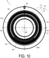
- FIG. 10 is a cross-sectional view schematically illustrating the suction strainer 5 taken along plane C-C in FIG. 9(A) .
- the baffle plate 62 is a lower cover having a cross-sectional shape that is an arc shape when taken along a plane (C-C plane) orthogonal to the central axis ax and provided at a position intersecting a line segment connecting the lower end portion of the filtration section 10 and the central axis ax.
- a central angle ⁇ 3 of the baffle plate 62 is approximately 90 degrees.
- the baffle plate 62 is provided along the pleated filter 12 adjacent to the pleated filter 12.
- the baffle plate 62 is provided so as not to abut on the pleated filter 12.
- the suction strainer 5 similarly to the suction strainer 1, when suctioned by the hydraulic pump (not illustrated in FIG. 9 ), the hydraulic fluid stored in the tank 100 is suctioned into the space S3 from the outside of the cover 40 via the hole 40a and the filtration section 10, and flows out from the space S3 to the suction pipe 101 via the hollow portion 21c and the hollow portion 22e.
- the floats 51 and 52 are pulled in the -z direction together with the hydraulic fluid, the float 51 closes the air vent hole 22f, and the float 52 closes the hole of the cover 40. Due to this, the hydraulic fluid does not flow into the space S3 from a portion other than the hole 40a and the filtration section 10.
- the bubbles V1 contained in the hydraulic fluid are also suctioned into the space S3 together with the hydraulic fluid.
- the hydraulic fluid flowing into the space S1 from the hole 40a and flowing into the space S2 from below the filtration section 10 is blocked by the baffle plate 62 and flows along the baffle plate 62 (see arrow in FIG. 9(B) ).
- the bubbles V1 passing through the pleated filter 11 together with the hydraulic fluid are blocked by the lower side of the baffle plate 62, and therefore the bubbles V1 hardly flow into the space S3.
- the baffle plate 62 blocks the bubbles V1 and the bubbles V1 hardly flow into the space S3, it is possible to prevent inflow of the bubbles into the hollow portion (space S3) of the filtration section 10. Even if the bubbles V1 flow into the space S3, the baffle plate 61C can retain the bubbles V2 in the space S3. As a result, outflow of the bubbles from the suction strainer 5 can be prevented.
- the suction strainer 5 includes the baffle plate 61C and the baffle plate 62, but the baffle plate 61C is not essential. Even when the suction strainer 5 includes only the baffle plate 62, an effect of preventing outflow of bubbles from the suction strainer 5 can be achieved.
- the baffle plate 62 is provided outside the pleated filter 12 and inside the pleated filter 11, but the position where the baffle plate (lower cover) is provided is not limited to this.
- the baffle plate (lower cover) may be provided below (-z side) the pleated filter 12 and below the central axis ax.
- the baffle plate 62A may be a lower cover provided outside the pleated filter 11.
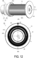
- FIGS. 11 and 12 are schematic diagrams illustrating suction strainers 5A and 5B having baffle plates 62B and 62C according to a modification, where (A) are perspective views, and (B) are cross-sectional views when taken along a plane orthogonal to the central axis ax. Note that FIGS. 11 and 12 partially omit hatching indicating a cross section. In FIGS. 11(A) and 12(A) , a part of the configuration is omitted.
- the baffle plates 62B and 62C are lower covers having a cross-sectional shape that is an arc shape when taken along a plane orthogonal to the central axis ax and provided at positions intersecting a line segment connecting the lower end portion of the filtration section 10 and the central axis ax.
- the baffle plates 62B and 62C are different from the baffle plate 62 only in the central angle. As illustrated in FIG. 11 , a central angle ⁇ 4 of the baffle plate 62B is approximately 120 degrees, and as illustrated in FIG. 12 , a central angle ⁇ 5 of the baffle plate 62C is approximately 180 degrees.
- the baffle plate (lower cover) may be disposed at least below the central axis ax of the filtration section 10, and a part of the baffle plate (lower cover) may be disposed at the same height as the central axis ax.
- the filtration section 10 includes the two pleated filters 11 and 12, but the number of pleated filters included in the filtration section 10 is not limited to this.
- the sixth embodiment of the present invention is a form in which the filtration section includes one pleated filter.
- description will be given of a suction strainer 6 according to the sixth embodiment. Note that the same components as those in the first embodiment are denoted by the same reference numerals, and descriptions thereof will be omitted.
- FIG. 13 is a cross-sectional view schematically illustrating a suction strainer 6. In FIG. 13 , hatching for indicating a cross section is omitted.
- the suction strainer 6 mainly includes the filtration section 10A, the attachment section 20A, the plate 30A, the float 53, and the baffle plate 62.
- the baffle plate 62 is provided along the pleated filter 12 adjacent to the pleated filter 12 of the filtration section 10A.
- the baffle plate 62 is provided so as not to abut on the pleated filter 12.
- the baffle plate 62 blocks the bubbles V1 and the bubbles V1 hardly flow into the space S3, whereby it is possible to prevent inflow of the bubbles into the hollow portion (space S3) of the filtration section 10A and to prevent outflow of the bubbles from the suction strainer 6 provided along the horizontal direction.
- the bubbles V2 accumulated on the air reservoir section 61a are discharged via the filtration section 10 after the hydraulic pump is stopped, but the form of discharge of the bubbles V2 is not limited to this.
- the seventh embodiment of the present invention is a form in which the bubbles V2 are discharged via the air vent hole.
- a suction strainer 7 according to the seventh embodiment will be described below. Note that the same components as those in the first embodiment are denoted by the same reference numerals, and descriptions thereof will be omitted.
- FIG. 14 is a cross-sectional view schematically illustrating a suction strainer 7.
- FIG. 14 partially omits hatching indicating a cross section.
- the suction strainer 7 mainly includes the filtration section 10, the attachment section 20, the plate 30, the cover 40, the floats 51 and 52, a baffle plate 61E, and the attachment section 70 (partially not illustrated in FIG. 14 ).
- the baffle plate 61E (corresponding to the first baffle plate of the present invention) is provided inside the filtration section 10. Similarly to the baffle plate 61, the baffle plate 61E includes an air reservoir section 61l having a cylindrical shape and an extension cylinder 61m having a cylindrical shape provided in the air reservoir section 61l.
- the baffle plate 61E is inserted into the hollow portion 22e of the cylindrical portion 22a, and has one end provided in the cylindrical portion 21a. Therefore, the space above the air reservoir section 61l communicates with the air vent hole 22f.
- the bubbles V2 flow into the air vent hole 22f and push up the float 52 in the +z direction, the holes of the cover 40 are opened, and the bubbles V2 are released from the space S1 to the outside of the suction strainer 1.
- the baffle plate 61E by blocking the bubbles V2 by the baffle plate 61E, it is possible to prevent outflow of the bubbles from the suction strainer 7 provided along the horizontal direction.
- the bubbles V2 can be discharged into the space S1 even during operation (during operation of the hydraulic pump 103).
- substantially is a concept not only including the case of being strictly the same, but also including an error and deformation to the extent that a loss of identity does not occur.
- the term “substantially orthogonal” is not limited to the case of being strictly orthogonal, but includes a concept that includes deviations of several degrees, for example.
- simple expressions such as orthogonal, parallel, and identical are not to be understood as merely being strictly, for example, orthogonal, parallel, and identical, and include being, for example, substantially parallel, substantially orthogonal, and substantially identical.
- vicinity means to include a region in a certain range (the range can be determined arbitrarily) near a reference position.
- a vicinity of an end refers to a range of regions in the vicinity of the end, and is a concept indicating that the end may or need not be included.
Landscapes
- Chemical & Material Sciences (AREA)
- Chemical Kinetics & Catalysis (AREA)
- Supply Devices, Intensifiers, Converters, And Telemotors (AREA)
- Filtration Of Liquid (AREA)
Applications Claiming Priority (2)
| Application Number | Priority Date | Filing Date | Title |
|---|---|---|---|
| JP2022059544A JP2023150437A (ja) | 2022-03-31 | 2022-03-31 | サクションストレーナ |
| PCT/JP2023/012606 WO2023190561A1 (ja) | 2022-03-31 | 2023-03-28 | サクションストレーナ |
Publications (2)
| Publication Number | Publication Date |
|---|---|
| EP4501428A1 true EP4501428A1 (de) | 2025-02-05 |
| EP4501428A4 EP4501428A4 (de) | 2025-08-13 |
Family
ID=88201901
Family Applications (1)
| Application Number | Title | Priority Date | Filing Date |
|---|---|---|---|
| EP23780570.0A Pending EP4501428A4 (de) | 2022-03-31 | 2023-03-28 | Saugsieb |
Country Status (5)
| Country | Link |
|---|---|
| US (1) | US20250018319A1 (de) |
| EP (1) | EP4501428A4 (de) |
| JP (1) | JP2023150437A (de) |
| CN (1) | CN118843502A (de) |
| WO (1) | WO2023190561A1 (de) |
Families Citing this family (1)
| Publication number | Priority date | Publication date | Assignee | Title |
|---|---|---|---|---|
| EP4670814A1 (de) * | 2024-06-26 | 2025-12-31 | Yamashin-Filter Corp. | Entlüftungsventil und filtervorrichtung |
Family Cites Families (10)
| Publication number | Priority date | Publication date | Assignee | Title |
|---|---|---|---|---|
| JPS4618529Y1 (de) * | 1968-06-15 | 1971-06-28 | ||
| JPS518176Y1 (de) * | 1970-10-27 | 1976-03-04 | ||
| JPS56159107U (de) * | 1980-04-25 | 1981-11-27 | ||
| JPS61163018U (de) * | 1985-03-29 | 1986-10-09 | ||
| JP3834523B2 (ja) * | 2002-04-11 | 2006-10-18 | インテグリス・インコーポレーテッド | コネクタ式のインラインフィルター |
| US8192622B2 (en) * | 2010-04-06 | 2012-06-05 | Kochek Company, Inc. | Strainer with bottom guard and counterweight |
| JP6659249B2 (ja) * | 2015-06-18 | 2020-03-04 | ヤマシンフィルタ株式会社 | サクションストレーナ |
| JP7143139B2 (ja) * | 2018-08-06 | 2022-09-28 | ヤマシンフィルタ株式会社 | サクションフィルタ |
| JP7262325B2 (ja) * | 2019-07-03 | 2023-04-21 | ヤマシンフィルタ株式会社 | タンク装置 |
| JP6830987B2 (ja) * | 2019-08-01 | 2021-02-17 | ヤマシンフィルタ株式会社 | サクションストレーナ |
-
2022
- 2022-03-31 JP JP2022059544A patent/JP2023150437A/ja active Pending
-
2023
- 2023-03-28 EP EP23780570.0A patent/EP4501428A4/de active Pending
- 2023-03-28 CN CN202380026140.3A patent/CN118843502A/zh active Pending
- 2023-03-28 WO PCT/JP2023/012606 patent/WO2023190561A1/ja not_active Ceased
-
2024
- 2024-09-27 US US18/899,604 patent/US20250018319A1/en active Pending
Also Published As
| Publication number | Publication date |
|---|---|
| EP4501428A4 (de) | 2025-08-13 |
| WO2023190561A1 (ja) | 2023-10-05 |
| US20250018319A1 (en) | 2025-01-16 |
| JP2023150437A (ja) | 2023-10-16 |
| CN118843502A (zh) | 2024-10-25 |
Similar Documents
| Publication | Publication Date | Title |
|---|---|---|
| CN109952137B (zh) | 过滤设备 | |
| JP4965507B2 (ja) | オイルフィルタ装置 | |
| US10792597B2 (en) | Suction strainer | |
| US20190091614A1 (en) | Filter device | |
| CN107614895B (zh) | 回流过滤器 | |
| US10525386B2 (en) | Filter device | |
| KR102000229B1 (ko) | 배관용 스트레이너 | |
| US10350527B2 (en) | Filter device and filtration device | |
| EP4501428A1 (de) | Saugsieb | |
| US10702808B2 (en) | Filter device and filtration device | |
| US20180229157A1 (en) | Return filter | |
| JP7143139B2 (ja) | サクションフィルタ | |
| KR102636377B1 (ko) | 필터 장치 | |
| KR101509234B1 (ko) | 스트레이너 필터조립체 | |
| EP3995197B1 (de) | Tankvorrichtung | |
| US20170340992A1 (en) | Filter apparatus | |
| US20240367075A1 (en) | Suction strainer | |
| US20240335774A1 (en) | Suction strainer | |
| KR102910274B1 (ko) | 압력 체크 및 필터 탈착이 용이한 버킷형 스트레이너 | |
| KR101786639B1 (ko) | 해수 흡입용 제진기 | |
| JP2018118204A (ja) | フィルタ装置 | |
| EP3684493B1 (de) | Interner kontinuierlicher luftbypass | |
| WO2024190590A1 (ja) | フィルタ装置及び濾過装置 | |
| KR20250018003A (ko) | 탈착용 여과 모듈 및 이를 이용한 스트레이너 | |
| CN120019850A (zh) | 一种液体过滤装置 |
Legal Events
| Date | Code | Title | Description |
|---|---|---|---|
| STAA | Information on the status of an ep patent application or granted ep patent |
Free format text: STATUS: THE INTERNATIONAL PUBLICATION HAS BEEN MADE |
|
| PUAI | Public reference made under article 153(3) epc to a published international application that has entered the european phase |
Free format text: ORIGINAL CODE: 0009012 |
|
| STAA | Information on the status of an ep patent application or granted ep patent |
Free format text: STATUS: REQUEST FOR EXAMINATION WAS MADE |
|
| 17P | Request for examination filed |
Effective date: 20241001 |
|
| AK | Designated contracting states |
Kind code of ref document: A1 Designated state(s): AL AT BE BG CH CY CZ DE DK EE ES FI FR GB GR HR HU IE IS IT LI LT LU LV MC ME MK MT NL NO PL PT RO RS SE SI SK SM TR |
|
| DAV | Request for validation of the european patent (deleted) | ||
| DAX | Request for extension of the european patent (deleted) | ||
| A4 | Supplementary search report drawn up and despatched |
Effective date: 20250711 |
|
| RIC1 | Information provided on ipc code assigned before grant |
Ipc: B01D 35/027 20060101AFI20250707BHEP Ipc: B01D 24/00 20060101ALI20250707BHEP Ipc: B01D 29/00 20060101ALI20250707BHEP Ipc: B01D 29/07 20060101ALI20250707BHEP |