EP4497901A2 - Elektrischer türöffner - Google Patents
Elektrischer türöffner Download PDFInfo
- Publication number
- EP4497901A2 EP4497901A2 EP24218748.2A EP24218748A EP4497901A2 EP 4497901 A2 EP4497901 A2 EP 4497901A2 EP 24218748 A EP24218748 A EP 24218748A EP 4497901 A2 EP4497901 A2 EP 4497901A2
- Authority
- EP
- European Patent Office
- Prior art keywords
- immobilization
- locking
- holding
- blocking
- electric strike
- Prior art date
- Legal status (The legal status is an assumption and is not a legal conclusion. Google has not performed a legal analysis and makes no representation as to the accuracy of the status listed.)
- Withdrawn
Links
Images


Classifications
-
- E—FIXED CONSTRUCTIONS
- E05—LOCKS; KEYS; WINDOW OR DOOR FITTINGS; SAFES
- E05B—LOCKS; ACCESSORIES THEREFOR; HANDCUFFS
- E05B47/00—Operating or controlling locks or other fastening devices by electric or magnetic means
- E05B47/0046—Electric or magnetic means in the striker or on the frame; Operating or controlling the striker plate
- E05B47/0047—Striker rotating about an axis parallel to the wing edge
-
- E—FIXED CONSTRUCTIONS
- E05—LOCKS; KEYS; WINDOW OR DOOR FITTINGS; SAFES
- E05B—LOCKS; ACCESSORIES THEREFOR; HANDCUFFS
- E05B15/00—Other details of locks; Parts for engagement by bolts of fastening devices
- E05B15/0053—Other details of locks; Parts for engagement by bolts of fastening devices means providing a stable, i.e. indexed, position of lock parts
- E05B15/008—Other details of locks; Parts for engagement by bolts of fastening devices means providing a stable, i.e. indexed, position of lock parts friction type
-
- E—FIXED CONSTRUCTIONS
- E05—LOCKS; KEYS; WINDOW OR DOOR FITTINGS; SAFES
- E05B—LOCKS; ACCESSORIES THEREFOR; HANDCUFFS
- E05B47/00—Operating or controlling locks or other fastening devices by electric or magnetic means
- E05B2047/0072—Operation
- E05B2047/0073—Current to unlock only
- E05B2047/0074—Current to unlock only holding means other than current (mechanical, magnetic)
-
- E—FIXED CONSTRUCTIONS
- E05—LOCKS; KEYS; WINDOW OR DOOR FITTINGS; SAFES
- E05B—LOCKS; ACCESSORIES THEREFOR; HANDCUFFS
- E05B47/00—Operating or controlling locks or other fastening devices by electric or magnetic means
- E05B47/0001—Operating or controlling locks or other fastening devices by electric or magnetic means with electric actuators; Constructional features thereof
- E05B47/0002—Operating or controlling locks or other fastening devices by electric or magnetic means with electric actuators; Constructional features thereof with electromagnets
- E05B47/0003—Operating or controlling locks or other fastening devices by electric or magnetic means with electric actuators; Constructional features thereof with electromagnets having a movable core
- E05B47/0004—Operating or controlling locks or other fastening devices by electric or magnetic means with electric actuators; Constructional features thereof with electromagnets having a movable core said core being linearly movable
Definitions
- the invention relates to an electric strike, more particularly an electric strike with memory, or even with emission.
- the present invention relates to the field of hardware and, more particularly, to the manufacture of security systems which are designed to lock, respectively unlock, an opening to prevent, respectively authorize, access to a place, in particular to a building.
- Electric strikes are already known which comprise at least one locking means, which is configured to lock an opening, and which can adopt an active locking position and an inactive locking position for such an opening.
- Such an electric strike can be of different types.
- a first type relates to a current-breaking electric strike which is designed such that, as long as the electric strike is supplied with electric current, the locking means adopts an active locking position in which the opening is locked and cannot be actuated. In the absence of an electric current supply to the electric strike, the locking means can then adopt an inactive locking position in which the opening is unlocked and can be actuated.
- a second type concerns a current-emitting electric strike which is designed such that, as long as the electric strike is not supplied with electric current, the locking means adopts an active locking position and the opening cannot be actuated.
- the locking means can adopt an inactive locking position in which the opening is unlocked and can be actuated.
- Such an electric strike includes a member which, depending on its positioning within the electric strike, allows this electric strike to be configured, as the case may be, on current failure or on current emission.
- the transition from an electric strike with current failure to an electric strike with current emission (and vice versa) requires the dismantling of the electric strike, the removal of said member, the modification of the positioning of this member, the replacement of this member within the strike and the reassembly of this strike, which results in long and tedious operations.
- a third type involves a memory electric strike which is designed so that, as long as the electric strike is not supplied with electrical current, the locking means adopts an active locking position, is immobilized in its active locking position, and the opening leaf cannot be actuated.
- the locking means When the electric strike is supplied with electrical current, the locking means is no longer immobilized in the active locking position and can adopt an inactive locking position, this as long as the locking means is not brought into the inactive locking position by the opening leaf and even after interruption of the electrical current supply to the electric strike.
- this locking means adopts an active locking position again, is immobilized in this active locking position, and the opening leaf cannot be actuated.
- Such an electric strike with memory has many components which complicates the design of such an electric strike. In addition, these components are small which weakens such an electric strike. In addition, these many components are mobile which increases the risk of failure of the electric strike. Finally, such an electric strike with memory cannot operate like a conventional current emission strike and vice versa.
- the present invention aims to remedy the drawbacks of electric strikes of the state of the art.
- the positioning means comprises, on the one hand, a ring which is movable in rotation about an axis of rotation and, on the other hand, a positioning finger, which cooperates with the holding means, which extends laterally relative to the ring and from this ring.
- the electric strike comprises a control means which is configured to control the passage of the holding means from the active holding position of the blocking means to the inactive holding position of the blocking means, this under the impulse of the movement of the immobilization means.
- the electric strike comprises an activation means which is configured to activate the inhibition means while the electric strike is configured such that this activation means is accessible from outside the housing.
- the electric strike according to the invention comprises a limited number of components which advantageously makes it possible to simplify the design of this electric strike, to stiffen the components by increasing their size, and thus to increase the reliability of such an electric strike compared to those of the state of the art.
- this electric strike comprises an inhibition means which is configured to inhibit the holding means which advantageously enables this electric strike to operate as an electric strike with current emission.
- This electric strike also comprises an activation means, which is configured to activate the inhibition means, and which then advantageously allows the operation of the electric strike to be selected either as an electric strike with memory or as an electric strike with current emission. Such activation is advantageously possible from outside the housing and without dismantling the electric strike.
- the present invention relates to the field of hardware and, more particularly, to the manufacture of security systems which are designed to lock, respectively unlock, an opening to prevent, respectively authorize, access to a place, in particular to a building.
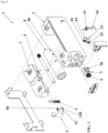
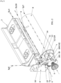
- the invention then relates to an electric strike 1 which is intended to equip a frame, which comprises a construction, and which delimits an opening.
- an electric strike 1 can be positioned at least partly inside a housing which comprises this frame.
- Such an electric strike 1 is configured to cooperate with an opening, which closes said opening, and which is mounted in movement (in particular in rotation) on said frame. Such an electric strike 1 can, then, cooperate with a bolt that comprises a lock that equips such an opening.
- Such an electric strike 1 comprises a housing 2 which equips said frame, in particular by being positioned at least partly inside a housing which this frame comprises.
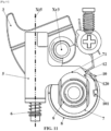
- Such an electric strike 1 comprises a locking means 3 which is configured to lock said opening relative to said frame. It is, more particularly, this locking means 3 which then cooperates with the bolt of the lock which equips said opening.
- Such a locking means 3 is movable between an active locking position of an opening ( Figures 2 to 7 And 12 has 14 ) and an inactive opening locking position ( Figures 8 to 11 ).
- Such a locking means 3 is movable in rotation about an axis of rotation Xr3, this between the active position and the inactive locking position.
- such locking means 3 may comprise a trigger or a half-turn.
- the electric strike 1 also comprises a return means 4 for the locking means 3 which is configured to drive the locking means 3 from the inactive position for locking the opening leaf to the active position for locking the opening leaf, this in rotation about the axis of rotation Xr3.
- a return means 4 may take the form of a torsion spring, in particular a helical spring.
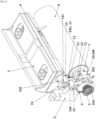
- Said electric strike 1 further comprises an immobilization means 5 which is configured to immobilize said locking means 3 which is in the active position of locking the opening.
- This immobilization means 5 is movable between, on the one hand, an active immobilization position of the locking means 3 (more particularly which is in the active locking position of the opening) and, on the other hand, an inactive immobilization position of the locking means 3 (more particularly which is in the active or inactive locking position of the opening).
- Such an immobilization means 5 is movable in translation along a translation axis Xt5 which can be perpendicular to the rotation axis Xr3.
- such immobilization means 5 may comprise a lateral immobilization finger 50 which cooperates with the locking means 3.
- Such a lateral immobilizing finger 50 can extend in a direction parallel to the axis of rotation Xr3.
- the electric strike 1 also comprises a return means 6 for the immobilization means 5 which is configured to drive the immobilization means 5 from the inactive immobilization position of the locking means 3 to the active immobilization position of the locking means 3, this in translation along the translation axis Xt5.
- a return means 6 can adopt the form of a compression spring, in particular a helical spring.
- the electric strike 1 further comprises a blocking means 7 which is configured to block the immobilization means 5 which is in the active immobilization position of the locking means 3 (more particularly which is in the active locking position of the opening).
- Such a blocking means 7 is movable between, on the one hand, an active blocking position of the immobilization means 5 (more particularly which is in the active immobilization position of the locking means 3 which is in the active locking position of the opening leaf) and, on the other hand, an inactive blocking position of the immobilization means 5 (more particularly which is in the active or inactive immobilization position of the locking means 3 which is in the active or inactive locking position of the opening leaf).
- Such a locking means 7 is movable in translation along a translation axis Xt7 which can be parallel to the rotation axis Xr3 and/or perpendicular to the translation axis Xt5.
- such a blocking means 7 comprises a carriage 70 which cooperates with the immobilization means 7. This carriage 70 is then movable in translation along the translation axis Xt7.
- the locking means 7 (more particularly the carriage 70) comprises, on the one hand, a bearing surface 71 against which the immobilization means 5 bears (more particularly which is in the active position of immobilization of the locking means 3) this in the active position of blocking of this immobilization means 5 by the locking means 7 and, on the other hand, a housing 72, which adjoins and/or which extends the bearing surface 71, and inside which the immobilization means 5 engages (more particularly which is in the active or inactive position of immobilization of the locking means 3) this in the inactive position of blocking of this immobilization means 5 by the locking means 7.
- the electric strike 1 further comprises a drive means 8 which is configured to drive the blocking means 7 from the active blocking position of the immobilization means 5 (more particularly which is in the active immobilization position of the locking means 3) to the inactive blocking position of the immobilization means 5 (more particularly which is in the active or inactive immobilization position of the locking means 3).
- this drive means 8 is configured to drive the blocking means 7 from the active blocking position to the inactive blocking position of the immobilization means 5, this under the impulse of a supply of electric current to the electric strike 1, more particularly to this drive means 8.
- Such a drive means 8 may comprise an electromagnet 80 which comprises a solenoid which extends along an axis which is parallel to the rotation axis Xr3 and/or which is at least parallel to (or even coincident with) the translation axis Xt7 along which the blocking means 7 is movable in translation.
- an electromagnet 80 which comprises a solenoid which extends along an axis which is parallel to the rotation axis Xr3 and/or which is at least parallel to (or even coincident with) the translation axis Xt7 along which the blocking means 7 is movable in translation.
- the electric strike 1 also comprises a return means 9 for the blocking means 7 which is configured to drive the blocking means 7 from the inactive blocking position of the immobilization means 5 to the active blocking position of the immobilization means 5, more particularly against the action of the drive means 8.
- Such a return means 9 can take the form of a compression spring, in particular a helical spring.
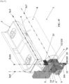
- the electric strike 1 further comprises a holding means 10 which is configured to hold the blocking means 7 in the inactive blocking position of the immobilization means 5.
- Such a holding means 10 is movable between, on the one hand, an active position for holding the blocking means 7 (more particularly which is in the position inactive blocking position of the immobilization means 5) and, on the other hand, an inactive position for maintaining the blocking means 7 (more particularly which is in the active or inactive blocking position).
- such a holding means 10 is configured to hold the blocking means 7 in the inactive blocking position of the immobilization means 5, this against the action of the return means 9 of the blocking means 7.
- Such a holding means 10 comprises, on the one hand, a holding member 100 which is deformable and/or which is movable and, on the other hand, a holding finger 101, which cooperates with the blocking means 7, and which extends laterally relative to the holding member 100 as well as from this holding member 100.
- a holding finger 101 may consist of a cutout and/or a deformation of an element which also comprises the holding member 100.
- said holding member 100 comprises (or is constituted by) at least one blade 102 which is deformable and/or which is movable in rotation around an axis of rotation Xr10 (which can be parallel to the axis of rotation Xr3 and/or to the axis of translation Xt7).
- the holding finger 101 which such a holding member 100 comprises, then extends laterally relative to the blade 102 and from this blade 102.
- At least part of such a holding means 10 (more particularly said at least one blade 102 and said holding finger 101) may be constituted by a folded sheet metal.
- said holding member 100 comprises (or is constituted by) at least one stud 103 which is movable in translation along a translation axis Xt10 (which can extend in a direction which can be parallel to the translation axis Xt5 and/or perpendicular to the rotation axis Xr3 and/or perpendicular to the translation axis Xt7) while the holding finger 101 extends laterally relative to the stud 103 and from this stud 103.
- a translation axis Xt10 which can extend in a direction which can be parallel to the translation axis Xt5 and/or perpendicular to the rotation axis Xr3 and/or perpendicular to the translation axis Xt7
- Such a stud 103 can adopt the shape of a tube and have a housing (in particular through) inside which is positioned a fixed shaft, which extends along said translation axis Xt10, and relative to which said stud 103 is movable in translation.
- the blocking means 7 comprises a support surface 73 against which the holding means 10 (more particularly the holding finger 101) bears, this in the active position of holding the blocking means 7 (by the holding means 10) in the inactive position of blocking the immobilization means 5 (by the blocking means 7).
- the electric strike 1 includes a return means 11 of the holding means 10 which is configured to drive the holding means 10 from the inactive holding position of the locking means 7 to the active position for holding the locking means 7.
- Such a return means 11 may be constituted by the blade 102 itself which may then be of the elastic type and/or by a torsion spring (in particular helical and/or which acts on such a blade 102) and/or by a compression spring (in particular which acts on said stud 103).
- the electric strike 1 also comprises a control means 12 which is configured to control the passage of the holding means 10 from the active position of holding the blocking means 7 (more particularly which is in the inactive position of blocking the immobilization means 5) to the inactive position of holding the blocking means 7.
- This control means 12 can be configured to exercise such a command against the action of the return means 11.
- the immobilization means 5 which comprises such a control means 12.
- This control means 12 may comprise a lateral control finger 120 which extends in a direction perpendicular to the axis of rotation Xr3 and perpendicular to the axis of translation Xt5 of the immobilization means 5.
- This immobilization means 5 can then comprise, on the one hand, the aforementioned lateral immobilization finger 50 and, on the other hand, the aforementioned lateral control finger 120.
- Said control means 12 is configured to control the holding means 10 under the impulse of the movement of the immobilization means 5 (more particularly from the active immobilization position of the locking means 3 to the inactive immobilization position of this locking means 3), this under the impulse of the movement of the locking means 3 (more particularly from the active locking position of the opening leaf to the inactive locking position of the opening leaf), in particular under the impulse of an actuation of this opening leaf.
- the electric strike 1 comprises an inhibition means 13 which is configured to inhibit the holding means 10. This inhibition means 13 then prevents the operation of this holding means 10 so that the blocking means 7 can no longer be held in the inactive blocking position of the immobilization means 5 by this holding means 10.
- this inhibition means 13 can then adopt, on the one hand, an active position of inhibition of the holding means 10.
- the holding means 10 cannot maintain the blocking means 7 in the inactive blocking position of the locking means 5 and this blocking means 7 is then only subject to the action of the drive means 8 and to the action of the return means 9.
- the electric strike 1 then adopts the operation of an electric strike with emission of current.
- this inhibition means 13 can adopt an inactive position of inhibition of the holding means 10. In this position, the holding means 10 can maintain the blocking means 7 in its inactive position of blocking the immobilization means 5.
- the electric strike 1 then adopts the operation of an electric strike with memory.
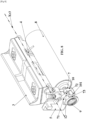
- this inhibition means 13 is rotatable about an axis of rotation which is parallel to the axis of rotation Xr3 of the locking means 3 and/or at least parallel to (or even, and preferably, coincident with) the axis of rotation Xr10 of the holding member 100.
- This inhibition means 13 is, then, rotatable about this axis of rotation, this between the inactive position ( Figures 2 to 11 ) and the active position ( Figures 12 to 14 ) inhibition of the holding means 10.
- the inhibiting means 13 comprises a positioning means 14 which is configured to position and maintain the holding means 10 in its inactive position for maintaining the blocking means 7.
- Such a positioning means 14 is, here again, movable in rotation about an axis of rotation which is parallel to the axis of rotation Xr3 of the locking means 3 and/or at least parallel to (or even, and preferably, coincident with) the axis of rotation Xr10 of the holding member 100.
- This positioning means 14 is, then, movable in rotation about this axis of rotation, this between an inactive position ( Figures 2 to 11 ) and an active position ( Figures 12 to 14 ) for maintaining the holding means 10 in its inactive position for maintaining the blocking means 7.
- Such a positioning means 14 comprises, on the one hand, a ring 140 which is movable in rotation about an axis of rotation, more particularly which is parallel to the axis of rotation Xr3 of the locking means 3 and/or at least parallel to (or even, and preferably, coincident with) the axis of rotation Xr10 of the holding member 10 and, on the other hand, a positioning finger 141, which cooperates with the holding means 10 (more particularly with a free end, which the holding member 100 comprises, and which is opposite an end of the holding member 100 from which the holding finger 101 extends, figures 12 And 13 ), and which extends laterally relative to the ring 140 and from this ring 140.
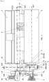
- the inhibition means 13 is movable in translation along a translation axis which is parallel to the translation axis Xt5 of the immobilization means 5 and/or at least parallel to (or, and preferably, coincident with) the translation axis Xt10 of the holding member 100.
- This inhibition means 13 is, then, movable in translation along this translation axis, this between the inactive position ( figures 15 And 16 ) and the active position ( figure 17 ) inhibition of the holding means 10.
- the inhibition means 13 again comprises a positioning means 14 which is configured to position and maintain the holding means 10 in its inactive position for maintaining the blocking means 7.
- Such a positioning means 14 is, here again, movable in translation along a translation axis which is parallel to the translation axis Xt5 of the immobilization means 5 and/or at least parallel to (or even, and preferably, coincident with) the translation axis Xt10 of the holding member 100.
- This positioning means 14 is, then, movable in translation along this translation axis, this between an inactive position ( figures 15 And 16 ) and an active position ( figure 17 ) for maintaining the holding means 10 in its inactive position for maintaining the blocking means 7.
- Such a positioning means 14 also comprises a ring which is movable in translation along a translation axis, more particularly which is parallel to the translation axis Xt5 of the immobilization means 5 and/or at least parallel to (or even, and preferably, coincident with) the translation axis Xt10 of the holding member 100.
- This ring then cooperates with the holding means 10, in particular with the holding member 100, more particularly with an end, which the holding member 100 comprises, and which is opposite an end of the holding member 100 from which the holding finger 101 extends.
- Said ring can then be positioned around the fixed shaft, which extends along said translation axis Xt10, and relative to which said stud 103 is movable in translation and also be movable in translation relative to this fixed shaft.
- the electric strike 1 comprises an activation means 15 which is configured to activate the inhibition means 13, more particularly to make this inhibition means 13 adopt an active position of inhibition of the holding means 10 and an inactive position of inhibition of this holding means 10.
- the electric strike 1 is configured so that the activation means 15 is accessible from outside the housing 2, more particularly without dismantling this housing 2.
- Such an activation means 15 may take the form of a screw or the like which is engaged with the aforementioned ring 140 or, again, the form of a member (in particular an imprint or the like) which this ring 140 comprises and which is capable of receiving an actuating tool (such as a screwdriver).
- the electric strike 1 may also comprise a locking means 16 which is configured to lock the inhibition means 13 (more particularly in its active or inactive inhibition position) and/or the activation means 15 of this inhibition means 13.
- such locking means 16 may comprise a screw.
- the electric strike 1 is configured so that the locking means 16 is accessible from outside the box 2, more particularly without dismantling this box 2.
- this housing 2 comprises, internally, at least part of the locking means 3, at least part (or even all) of the immobilization means 5, at least part (or even all) of the blocking means 7, at least part (or even all) of the drive means 8, at least part (or even all) of the holding means 10, at least part (or even all) of the control means 12 and at least part (or even all) of the inhibition means 13.
- This housing 2 then also comprises, internally, at least part (or even all) of the return means (4, 6, 9, 11).
- this holding means 10 can adopt an active position for holding the blocking means 7 and the electric strike 1 can adopt the operation of an electric strike with memory.
- the locking means 3 In the absence of a power supply to the electric strike 1, the locking means 3 is in the active position for locking the opening, the immobilization means 5 is in the active position for immobilizing the locking means 3, the blocking means 7 is in the active position for blocking the immobilization means 5 and the holding means 10 is in the inactive position for holding the blocking means 7 ( Figures 2 to 4 ).
- an electric current supplies the drive means 8 which drives the locking means 7 from the active locking position of the immobilization means 5 to the inactive locking position of the immobilization means 5.
- the holding means 10 passes from the inactive holding position of the locking means 7 to the active holding position of the locking means 7 (in the inactive locking position of the immobilization means 5), in particular under the effect of the return means 11.
- This locking means 7 is held in the inactive locking position of the immobilization means 5 by the holding means 10.
- This immobilization means 5 is then free to pass from the active immobilization position of the locking means 3 to the inactive immobilization position of the locking means 3.
- This locking means 3 is free to pass from the active locking position of the opening leaf to the inactive locking position of the opening leaf, in particular under the impulse of the actuation of this opening Figures 5 to 7 ).
- This configuration is maintained as long as the opening is not activated.
- the locking means 3 moves from the active position for locking the opening leaf to the inactive position for locking the opening leaf.
- This locking means 3 then drives the immobilization means 5 which moves from the active position for immobilizing the locking means 3 to the inactive position for immobilizing the locking means 3.
- the control means 12 controls the holding means 10 which moves from the active position for holding the blocking means 7 to the inactive position for holding the blocking means 7.
- the blocking means 7 moves from the inactive position for blocking the immobilization means 5 towards the active position for blocking the immobilization means 5 ( Figures 8 to 11 ).
- the locking means 3 moves from the inactive position for locking the opening leaf to the active position for locking the opening leaf, this under the effect of the return means 4.
- the immobilization means 5 then moves from the inactive position for immobilizing the locking means 3 to the active position for immobilizing the locking means 3, this under the effect of the return means 6.
- the blocking means 7 moves from the inactive position for blocking the blocking means 5 to the active position for blocking the blocking means 5, this under the effect of the return means 9.
- this holding means 10 adopts an inactive position of holding the blocking means 7 and the electric strike 1 can adopt the operation of an electric strike with current emission.
- the locking means 3 In the absence of a power supply to the electric strike 1, the locking means 3 is in the active position for locking the opening, the immobilization means 5 is in the active position for immobilizing the locking means 3, the blocking means 7 is in the active position for blocking the immobilization means 5 ( Figures 12 to 14 ).
- an electric current supplies the drive means 8 which drives the blocking means 7 from the active blocking position of the immobilization means 5 to the inactive blocking position of the immobilization means 5.
- the immobilization means 5 is then free to move from the active immobilization position of the locking means 3 to the inactive immobilization position of the locking means 3.
- This locking means 3 is free to move from the active locking position of the opening leaf to the inactive locking position of the opening leaf, in particular under the impulse of the actuation of this opening leaf.
- the locking means 3 moves from the active opening leaf locking position to the inactive opening leaf locking position.
- This locking means 3 then drives the immobilization means 5 which passes from the active immobilization position of the locking means 3 to the inactive immobilization position of the locking means 3.
- the locking means 3 passes from the inactive locking position of the opening to the active locking position of the opening, this under the effect of the return means 4.
- the immobilization means 5 then passes from the inactive immobilization position of the locking means 3 to the active immobilization position of the locking means 3, this under the effect of the return means 6.
- the blocking means 7 passes from the inactive blocking position of the immobilization means 5 to the active blocking position of the immobilization means 5, this under the effect of the return means 9.
Landscapes
- Motor Or Generator Frames (AREA)
- Details Of Connecting Devices For Male And Female Coupling (AREA)
- Switch Cases, Indication, And Locking (AREA)
- Lock And Its Accessories (AREA)
Applications Claiming Priority (2)
| Application Number | Priority Date | Filing Date | Title |
|---|---|---|---|
| FR2113436A FR3130306B1 (fr) | 2021-12-14 | 2021-12-14 | Gâche électrique |
| EP22212314.3A EP4198224B1 (de) | 2021-12-14 | 2022-12-08 | Elektrischer türöffner |
Related Parent Applications (2)
| Application Number | Title | Priority Date | Filing Date |
|---|---|---|---|
| EP22212314.3A Division EP4198224B1 (de) | 2021-12-14 | 2022-12-08 | Elektrischer türöffner |
| EP22212314.3A Division-Into EP4198224B1 (de) | 2021-12-14 | 2022-12-08 | Elektrischer türöffner |
Publications (2)
| Publication Number | Publication Date |
|---|---|
| EP4497901A2 true EP4497901A2 (de) | 2025-01-29 |
| EP4497901A3 EP4497901A3 (de) | 2025-04-09 |
Family
ID=80786277
Family Applications (3)
| Application Number | Title | Priority Date | Filing Date |
|---|---|---|---|
| EP24218748.2A Withdrawn EP4497901A3 (de) | 2021-12-14 | 2022-12-08 | Elektrischer türöffner |
| EP24215530.7A Pending EP4488480A3 (de) | 2021-12-14 | 2022-12-08 | Elektrischer türöffner |
| EP22212314.3A Active EP4198224B1 (de) | 2021-12-14 | 2022-12-08 | Elektrischer türöffner |
Family Applications After (2)
| Application Number | Title | Priority Date | Filing Date |
|---|---|---|---|
| EP24215530.7A Pending EP4488480A3 (de) | 2021-12-14 | 2022-12-08 | Elektrischer türöffner |
| EP22212314.3A Active EP4198224B1 (de) | 2021-12-14 | 2022-12-08 | Elektrischer türöffner |
Country Status (3)
| Country | Link |
|---|---|
| EP (3) | EP4497901A3 (de) |
| ES (1) | ES3021874T3 (de) |
| FR (1) | FR3130306B1 (de) |
Family Cites Families (5)
| Publication number | Priority date | Publication date | Assignee | Title |
|---|---|---|---|---|
| DE29620290U1 (de) * | 1996-11-21 | 1997-01-23 | Yu's Electric Co., Ltd., Taipeh/T'ai-pei | Türschloß |
| US20100116006A1 (en) * | 2008-11-07 | 2010-05-13 | Chien-Ying Huang | Strike lock with functions of fail security and fail safety |
| DE102010018177A1 (de) * | 2010-04-22 | 2011-10-27 | Dorma Gmbh + Co. Kg | Türöffner |
| DE202011105510U1 (de) * | 2011-05-24 | 2012-08-28 | Assa Abloy Sicherheitstechnik Gmbh | Türöffner mit Sperr-Riegel |
| DE102012010439B4 (de) * | 2011-05-24 | 2016-01-07 | Assa Abloy Sicherheitstechnik Gmbh | Türöffner mit Sperr-Riegel |
-
2021
- 2021-12-14 FR FR2113436A patent/FR3130306B1/fr active Active
-
2022
- 2022-12-08 EP EP24218748.2A patent/EP4497901A3/de not_active Withdrawn
- 2022-12-08 EP EP24215530.7A patent/EP4488480A3/de active Pending
- 2022-12-08 ES ES22212314T patent/ES3021874T3/es active Active
- 2022-12-08 EP EP22212314.3A patent/EP4198224B1/de active Active
Also Published As
| Publication number | Publication date |
|---|---|
| ES3021874T3 (en) | 2025-05-27 |
| EP4488480A2 (de) | 2025-01-08 |
| EP4198224B1 (de) | 2025-01-29 |
| EP4488480A3 (de) | 2025-04-09 |
| EP4497901A3 (de) | 2025-04-09 |
| FR3130306A1 (fr) | 2023-06-16 |
| EP4198224A1 (de) | 2023-06-21 |
| FR3130306B1 (fr) | 2024-07-26 |
Similar Documents
| Publication | Publication Date | Title |
|---|---|---|
| EP0235041B1 (de) | Verriegelungsvorrichtung, zum Beispiel für einen Riegelverschluss | |
| EP0341132B1 (de) | Verriegelung mit entkuppelbarem Rotor | |
| FR3080880A1 (fr) | Dispositif de verrouillage a verrou rotatif a commande impulsionnelle | |
| BE1020832A3 (fr) | Dispositif de commande de verrouillage pour vantail. | |
| EP4198224B1 (de) | Elektrischer türöffner | |
| EP0262059B1 (de) | Schlüssel und Schloss | |
| FR2689926A1 (fr) | Dispositif de verrouillage à au moins un point de condamnation. | |
| EP0928870B1 (de) | Gleitstangenverschluss oder Gleitstangenschloss für Tür, Fenstertür oder dergleichen | |
| EP4177425B1 (de) | Externes öffnungssteuergerät für eine kraftfahrzeugöffnung | |
| EP2750938B1 (de) | Diebstahlschutzeinrichtung für eine lenksäule und zugehörige lenksäule | |
| EP3042014B1 (de) | Schloss für die tür eines kraftfahrzeuges | |
| EP1734552B1 (de) | Betätigungseinrichtung eines elektrischen Schaltgeräts mit Drehsperre | |
| EP0243214B1 (de) | Verriegelungsvorrichtung verwendbar als Diebstahlsicherung für ein elektrisches Kraftfahrzeugtürschloss und übereinstimmendes Schloss | |
| EP3808925B1 (de) | Schloss für einen öffnungsflügel eines kraftfahrzeugs | |
| CA2127480C (fr) | Dispositif de verrouillage a commande magnetique | |
| FR2773579A1 (fr) | Ferrure de verrouillage pour porte, porte-fenetre ou analogue munie d'un pene demi-tour a rappel elastique en position de verrouillage | |
| EP1637676B1 (de) | Türgriff und Verfahren zur Montage desgleichen | |
| EP2704926B1 (de) | Diebstahlschutzvorrichtung für lenksäule und entsprechende lenksäule | |
| FR2792964A1 (fr) | Serrure manoeuvrable electriquement ou mecaniquement | |
| EP0628681B1 (de) | Vorrichtung zusammengebaut aus einem Schloss und seiner Betätigungsnocke | |
| EP2736773A1 (de) | Diebstahlsichere vorrichtung für die lenksäule eines kraftfahrzeugs | |
| FR2769938A1 (fr) | Serrure electrique commandee par un interrupteur susceptible d'etre inhibe | |
| FR2699954A1 (fr) | Dispositif de montage d'une serrure-antivol. | |
| FR2847928A3 (fr) | Dispositif de condamnation d'un organe mobile | |
| TH40209A3 (th) | แท่งจุดไฟก๊าซ |
Legal Events
| Date | Code | Title | Description |
|---|---|---|---|
| PUAI | Public reference made under article 153(3) epc to a published international application that has entered the european phase |
Free format text: ORIGINAL CODE: 0009012 |
|
| STAA | Information on the status of an ep patent application or granted ep patent |
Free format text: STATUS: THE APPLICATION HAS BEEN PUBLISHED |
|
| AC | Divisional application: reference to earlier application |
Ref document number: 4198224 Country of ref document: EP Kind code of ref document: P |
|
| AK | Designated contracting states |
Kind code of ref document: A2 Designated state(s): AL AT BE BG CH CY CZ DE DK EE ES FI FR GB GR HR HU IE IS IT LI LT LU LV MC ME MK MT NL NO PL PT RO RS SE SI SK SM TR |
|
| REG | Reference to a national code |
Ref country code: DE Ref legal event code: R079 Free format text: PREVIOUS MAIN CLASS: E05B0015000000 Ipc: E05B0047000000 |
|
| PUAL | Search report despatched |
Free format text: ORIGINAL CODE: 0009013 |
|
| AK | Designated contracting states |
Kind code of ref document: A3 Designated state(s): AL AT BE BG CH CY CZ DE DK EE ES FI FR GB GR HR HU IE IS IT LI LT LU LV MC ME MK MT NL NO PL PT RO RS SE SI SK SM TR |
|
| RIC1 | Information provided on ipc code assigned before grant |
Ipc: E05B 15/00 20060101ALI20250228BHEP Ipc: E05B 47/00 20060101AFI20250228BHEP |
|
| STAA | Information on the status of an ep patent application or granted ep patent |
Free format text: STATUS: THE APPLICATION IS DEEMED TO BE WITHDRAWN |
|
| 18D | Application deemed to be withdrawn |
Effective date: 20251010 |