EP0628681B1 - Vorrichtung zusammengebaut aus einem Schloss und seiner Betätigungsnocke - Google Patents
Vorrichtung zusammengebaut aus einem Schloss und seiner Betätigungsnocke Download PDFInfo
- Publication number
- EP0628681B1 EP0628681B1 EP19940108531 EP94108531A EP0628681B1 EP 0628681 B1 EP0628681 B1 EP 0628681B1 EP 19940108531 EP19940108531 EP 19940108531 EP 94108531 A EP94108531 A EP 94108531A EP 0628681 B1 EP0628681 B1 EP 0628681B1
- Authority
- EP
- European Patent Office
- Prior art keywords
- control cam
- lock assembly
- assembly
- lock
- housing
- Prior art date
- Legal status (The legal status is an assumption and is not a legal conclusion. Google has not performed a legal analysis and makes no representation as to the accuracy of the status listed.)
- Expired - Lifetime
Links
Images


Classifications
-
- E—FIXED CONSTRUCTIONS
- E05—LOCKS; KEYS; WINDOW OR DOOR FITTINGS; SAFES
- E05B—LOCKS; ACCESSORIES THEREFOR; HANDCUFFS
- E05B9/00—Lock casings or latch-mechanism casings ; Fastening locks or fasteners or parts thereof to the wing
- E05B9/08—Fastening locks or fasteners or parts thereof, e.g. the casings of latch-bolt locks or cylinder locks to the wing
- E05B9/084—Fastening of lock cylinders, plugs or cores
- E05B9/086—Fastening of rotors, plugs or cores to an outer stator
Definitions
- the present invention relates, in general, to an assembly device between a lock assembly and its control cam.
- It relates more particularly to locks intended to equip a steering lock box for a motor vehicle.
- Such a housing is generally generally cylindrical in shape and has a bore inside which is housed a lock consisting of a rotor or barrel journalling in the bore, said rotor being made integral with a control cam intended for training a bolt.
- the lock assembly and its associated cam is either produced in a single piece, or assembled before its introduction into the anti-theft case.
- control cam is pre-assembled in the anti-theft housing.
- the assembly thus formed must be equipped with the lock assembly and its rotor must be made integral in rotation and in translation with the control cam.
- the device allowing this joining or assembly must be able to be implemented without special tools and include a reduced number of parts so that its cost is compatible with mass production as is the case in the automotive field.
- this joining must take place for a predetermined relative position of the cam and of the rotor known as the mounting position and be effective, after rotation of the rotor, including in said mounting position so that it is impossible to the user can extract the rotor from the lock from its housing and therefore dissociate it from its control cam.
- the present invention solves these problems and proposes for this purpose a device to be produced by assembly between a lock assembly, a motor vehicle steering lock box, and a control cam previously assembled to the box in a different angular assembly position.
- the lock assembly having at the end of a rotor, a coupling nose intended to cooperate with a housing of the control cam to establish a rotational connection between the assembly lock and the control cam, characterized in that it comprises, associated with first means of fastening in translation between the lock assembly and the control cam, active whatever the relative angular positions, of said lock assembly and of said control cam, second means for securing in translation between the lock assembly and the housing, active for at least one angular position predetermined relative value of the lock assembly, including the control cam, relative to the housing, different from the assembly position.
- the present invention also relates to a steering lock for a motor vehicle comprising in particular a lock assembly and a control cam, characterized in that said control cam and said lock assembly are assembled by means of an assembly device.
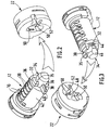
- FIG. 1 illustrates a lock assembly 10 consisting of a rotor 12 and a sheath or stator 14 integral with said rotor, the assembly being able to be operated by a conforming key 16.
- the lock assembly 10 is intended to be inserted, along arrow F, in a housing 18 provided in an anti-theft case 20.
- This box is pre-equipped with a control cam 22 intended to actuate a bolt (not shown) which, in locking position, immobilizes in rotation an essential member of the vehicle, for example the steering column.
- the cam 22 is made integral with the housing 20 by means which, not forming part of the present invention, have not been shown.
- the control cam 22 has a housing 24 fitted with a clip-on straw 26 returned radially towards the axis of the housing 20 by a spring 28.
- the rotor 12 is generally cylindrical in shape and comprises, in a manner known per se, radial housings 30 intended to receive pairs of flakes or pistons (not shown) .
- the rear face 32 of the rotor 12, opposite the entry face of the key 16, is extended by a coupling nose 34, the central part 35 of which is generally cylindrical.
- the coupling nose On either side of the central part 35 and adjacent to the rear face 32 of the rotor 12 the coupling nose has two diametrically opposite radial pins 36.
- the coupling nose 34 Perpendicular to the studs 36, the coupling nose 34 has a radial arm 38 of generally parallelepiped shape, the end 40 of which projects from the external surface 42 of the rotor 12.
- the coupling nose 34 On the side opposite to the radial arm 38, the coupling nose 34 has, on the one hand, a notch 44 (see FIG. 3) and, on the other hand, an inclined face 46.
- the control cam 22 has a housing 48 intended to receive the coupling nose 34.
- the housing 48 has two diametrically opposite radial branches 50 of complementary shape to the studs 46 and a radial slot 52 perpendicular to the arms 50 and of complementary shape to the arm 38 of the nose coupling 34.
- the assembly of the lock assembly 10 to the control cam 22 is carried out as follows.
- control cam 22 is angularly prepositioned in the body 20 of the anti-theft device in a position different from the locking position or "stop" position of the anti-theft device, for example the so-called “accessory” position. ", hereinafter referred to as the assembly position.
- a branch 54 of the clip-on straw 24 is opposite a notch 56 of the body 20 of the anti-theft device.
- the coupling nose 34 penetrates into the housing 48 of the control cam 22.
- the lower end of the clip-on straw 24 comes to bear on the inclined face 46 of the coupling nose 34 and moves radially outwards against the spring 26 and the end of the branch 56 of the straw 24 enters the notch 56 of the body 20.
- the straw 24 arrives opposite the notch 44 formed on the coupling nose 34 and enters there under the action of the spring 26.
- the lock assembly 10 is made, on the one hand, integral in rotation with the control cam 22 by cooperation of the radial pins 36 with the branches 50 of the housing 48 and, on the other hand, integral in translation of said control cam by cooperation of the clip-on straw 24 with the notch 44 of the coupling nose 34.
- the radial arm 38 constitutes second means for securing in translation, active means for at least one relative angular position different from the assembly position.
Landscapes
- Engineering & Computer Science (AREA)
- Mechanical Engineering (AREA)
- Lock And Its Accessories (AREA)
Claims (7)
- Vorrichtung, die aus einem Schloß (10), einem Lenkschloßgehäuse (20) eines Kraftfahrzeugs und einer Betätigungsnocke (22) zusammenzubauen ist, die zuvor am Gehäuse (20) in einer Zusammenbauwinkelposition angebracht wird, die sich von der Verriegelungsposition des Lenkschlosses unterscheidet, wobei das Schloß (10) am Ende eines Rotors (12) eine Anschlußnase (34) aufweist, die für das Zusammenwirken mit einer Aufnahme (48) der Betätigungsnocke (22) bestimmt ist, um eine drehfeste Verbindung zwischen dem Schloß (10) und der Betätigungsnocke (22) herzustellen, dadurch gekennzeichnet, daß sie in Verbindung mit ersten Mitteln (24, 26, 44) für eine verschiebungsfeste Verbindung zwischen dem Schloß (10) und der Betätigungsnocke (22), die unabhängig von den relativen Winkelpositionen des besagten Schlosses (10) und der besagten Betätigungsnocke (22) wirksam sind, zweite Mittel (38) für eine verschiebungsfeste Verbindung zwischen dem Schloß (10) und dem Gehäuse (20) umfaßt, die bei mindestens einer vorbestimmten relativen Winkelposition des Schlosses (10), einschließlich der Betätigungsnocke (22) , im Verhältnis zum Gehäuse (20) wirksam sind, die sich von der Zusammenbauposition unterscheidet.
- Vorrichtung nach Anspruch 1, dadurch gekennzeichnet, daß die ersten Mittel für die verschiebungsfeste Verbindung eine an der Anschlußnase (34) eingearbeitete Ausklinkung (44) umfassen, die für das Zusammenwirken mit einer Aufklemmzuhaltung (24) der Betätigungsnocke (22) bestimmt ist.
- Vorrichtung nach Anspruch 2, dadurch gekennzeichnet, daß die Aufklemmzuhaltung (24) einen Schenkel (54) umfaßt, der in eine Ausklinkung (56) des Gehäuses (20) bei einer einzigen relativen Position des Schlosses (10) und der Betätigungsnocke (22) eingreifen kann.
- Vorrichtung nach Anspruch 3, dadurch gekennzeichnet, daß die einzige relative Position der Zusammenbauposition des Schlosses (10) mit der Betätigungsnocke (22) entspricht.
- Vorrichtung nach einem der vorangehenden Ansprüche, dadurch gekennzeichnet, daß die Anschlußnase (34) an ihrem Ende eine abgeschrägte Teilfläche (46) umfaßt.
- Vorrichtung nach Anspruch 1, dadurch gekennzeichnet, daß die zweiten Mittel für eine verschiebungsfeste Verbindung aus einem radialen Arm (38) der Anschlußnase (34) bestehen.
- Lenkschloß für ein Kraftfahrzeug, das insbesondere ein Schloß (10) und eine Betätigungsnocke (22) enthält, dadurch gekennzeichnet, daß es eine Vorrichtung nach einem der vorangehenden Ansprüche umfaßt.
Applications Claiming Priority (2)
| Application Number | Priority Date | Filing Date | Title |
|---|---|---|---|
| FR9306913A FR2706516B1 (fr) | 1993-06-09 | 1993-06-09 | Dispositif d'assemblage entre un ensemble serrure et sa came de commande. |
| FR9306913 | 1993-06-09 |
Publications (2)
| Publication Number | Publication Date |
|---|---|
| EP0628681A1 EP0628681A1 (de) | 1994-12-14 |
| EP0628681B1 true EP0628681B1 (de) | 1997-10-29 |
Family
ID=9447921
Family Applications (1)
| Application Number | Title | Priority Date | Filing Date |
|---|---|---|---|
| EP19940108531 Expired - Lifetime EP0628681B1 (de) | 1993-06-09 | 1994-06-03 | Vorrichtung zusammengebaut aus einem Schloss und seiner Betätigungsnocke |
Country Status (6)
| Country | Link |
|---|---|
| EP (1) | EP0628681B1 (de) |
| CN (1) | CN1079480C (de) |
| BR (1) | BR9402122A (de) |
| DE (1) | DE69406495T2 (de) |
| ES (1) | ES2110653T3 (de) |
| FR (1) | FR2706516B1 (de) |
Families Citing this family (2)
| Publication number | Priority date | Publication date | Assignee | Title |
|---|---|---|---|---|
| US6463774B2 (en) * | 2000-05-17 | 2002-10-15 | Southco, Inc. | Push lock |
| JP4157816B2 (ja) * | 2003-09-03 | 2008-10-01 | 株式会社日中製作所 | 組プレートの取付装置 |
Family Cites Families (3)
| Publication number | Priority date | Publication date | Assignee | Title |
|---|---|---|---|---|
| US4347721A (en) * | 1980-07-02 | 1982-09-07 | Haworth Mfg., Inc. | Plug-type lock with increased stroke |
| DE8915331U1 (de) * | 1989-02-18 | 1990-04-12 | Martin Lehmann Gmbh & Co Kg, 4950 Minden, De | |
| US5119654A (en) * | 1990-12-11 | 1992-06-09 | Euro-Locks, S.A. | Cylinder locks having removable lock barrels |
-
1993
- 1993-06-09 FR FR9306913A patent/FR2706516B1/fr not_active Expired - Lifetime
-
1994
- 1994-05-31 BR BR9402122A patent/BR9402122A/pt not_active IP Right Cessation
- 1994-06-03 ES ES94108531T patent/ES2110653T3/es not_active Expired - Lifetime
- 1994-06-03 DE DE1994606495 patent/DE69406495T2/de not_active Expired - Lifetime
- 1994-06-03 CN CN94106526A patent/CN1079480C/zh not_active Expired - Fee Related
- 1994-06-03 EP EP19940108531 patent/EP0628681B1/de not_active Expired - Lifetime
Also Published As
| Publication number | Publication date |
|---|---|
| CN1079480C (zh) | 2002-02-20 |
| DE69406495D1 (de) | 1997-12-04 |
| ES2110653T3 (es) | 1998-02-16 |
| FR2706516B1 (fr) | 1995-07-28 |
| CN1115353A (zh) | 1996-01-24 |
| BR9402122A (pt) | 1995-01-10 |
| EP0628681A1 (de) | 1994-12-14 |
| FR2706516A1 (fr) | 1994-12-23 |
| DE69406495T2 (de) | 1998-02-26 |
Similar Documents
| Publication | Publication Date | Title |
|---|---|---|
| EP2024219B1 (de) | System zur arretierung eines schafts in einer bestimmten lage im verhältnis zu einem anderen schaft unter eliminierung des spielraums zwischen den beiden schäften | |
| EP0647752A2 (de) | Entkuppelbares Schloss für Kraftfahrzeuge und dgl. | |
| EP2614201B1 (de) | Schubriegelschloss für ein verriegelungssystem eines kraftfahrzeugs | |
| FR2678312A1 (fr) | Verrou a rotor debrayable. | |
| EP0628681B1 (de) | Vorrichtung zusammengebaut aus einem Schloss und seiner Betätigungsnocke | |
| EP2435649B1 (de) | Schloss und diebstahlsicherung für ein kraftfahrzeug | |
| EP3042014B1 (de) | Schloss für die tür eines kraftfahrzeuges | |
| EP1020337A1 (de) | Kraftfahrzeuglenkungs- Diebstahlsicherung | |
| FR2614921A1 (fr) | Dispositif de securite a l'arrachement et a l'enfoncement d'une piece emmanchee dans une autre piece, et ensemble formant serrure de surete equipe de ce dispositif | |
| FR2784148A1 (fr) | Dispositif d'accouplement entre un bouton de commande et un mecanisme | |
| EP3041715A1 (de) | Diebstahlschutzvorrichtung für die lenksäule eines kraftfahrzeugs | |
| EP0620339B1 (de) | Einrichtung zur Befestigung eines Schlosses in seinem Gehäuse | |
| EP0571249B1 (de) | Riegel mit entkuppelbarem Rotor, insbesondere für ein Kraftfahrzeug | |
| EP0742329A1 (de) | Verriegelungsvorrichtung für Kraftwagenflügel mit verbesserten Einbaumitteln für Verkleidungskappe | |
| FR3107295A1 (fr) | Dispositif de verrouillage pour une pièce mobile d’un véhicule | |
| EP0628455A1 (de) | Lenkradschloss für Kraftfahrzeug | |
| EP2736773B1 (de) | Antidiebstahlvorrichtung für eine lenksäule eines kraftfahrzeuges | |
| EP0457633B1 (de) | Einrichtung für Befestigung eines Schlosses in einem Türgriff, insbesondere der Griff einer Autotür | |
| WO2017140996A1 (fr) | Verrou pour vehicule automobile | |
| WO2005058552A2 (fr) | Dispositif d’assemblage du carter et du corps d’un brise-roche hydraulique | |
| EP0688925A1 (de) | Drehriegel mit verbesserter Verbindungsvorrichtung | |
| FR2787489A1 (fr) | Serrure a corps plastique clipsable dans une ouverture d'un support | |
| FR2924734A1 (fr) | Verrou a dispositif de blocage du rotor | |
| FR2697863A1 (fr) | Dispositif de verrouillage d'une serrure dans son support. |
Legal Events
| Date | Code | Title | Description |
|---|---|---|---|
| PUAI | Public reference made under article 153(3) epc to a published international application that has entered the european phase |
Free format text: ORIGINAL CODE: 0009012 |
|
| AK | Designated contracting states |
Kind code of ref document: A1 Designated state(s): DE ES GB IT |
|
| 17P | Request for examination filed |
Effective date: 19950513 |
|
| 17Q | First examination report despatched |
Effective date: 19960701 |
|
| GRAG | Despatch of communication of intention to grant |
Free format text: ORIGINAL CODE: EPIDOS AGRA |
|
| GRAH | Despatch of communication of intention to grant a patent |
Free format text: ORIGINAL CODE: EPIDOS IGRA |
|
| GRAH | Despatch of communication of intention to grant a patent |
Free format text: ORIGINAL CODE: EPIDOS IGRA |
|
| GRAA | (expected) grant |
Free format text: ORIGINAL CODE: 0009210 |
|
| AK | Designated contracting states |
Kind code of ref document: B1 Designated state(s): DE ES GB IT |
|
| GBT | Gb: translation of ep patent filed (gb section 77(6)(a)/1977) |
Effective date: 19971103 |
|
| REF | Corresponds to: |
Ref document number: 69406495 Country of ref document: DE Date of ref document: 19971204 |
|
| ITF | It: translation for a ep patent filed |
Owner name: SOCIETA' ITALIANA BREVETTI S.P.A. |
|
| REG | Reference to a national code |
Ref country code: ES Ref legal event code: FG2A Ref document number: 2110653 Country of ref document: ES Kind code of ref document: T3 |
|
| PLBE | No opposition filed within time limit |
Free format text: ORIGINAL CODE: 0009261 |
|
| STAA | Information on the status of an ep patent application or granted ep patent |
Free format text: STATUS: NO OPPOSITION FILED WITHIN TIME LIMIT |
|
| 26N | No opposition filed | ||
| REG | Reference to a national code |
Ref country code: GB Ref legal event code: IF02 |
|
| PGFP | Annual fee paid to national office [announced via postgrant information from national office to epo] |
Ref country code: GB Payment date: 20040528 Year of fee payment: 11 |
|
| PG25 | Lapsed in a contracting state [announced via postgrant information from national office to epo] |
Ref country code: GB Free format text: LAPSE BECAUSE OF NON-PAYMENT OF DUE FEES Effective date: 20050603 |
|
| GBPC | Gb: european patent ceased through non-payment of renewal fee |
Effective date: 20050603 |
|
| PGFP | Annual fee paid to national office [announced via postgrant information from national office to epo] |
Ref country code: DE Payment date: 20120622 Year of fee payment: 19 |
|
| PGFP | Annual fee paid to national office [announced via postgrant information from national office to epo] |
Ref country code: IT Payment date: 20120629 Year of fee payment: 19 Ref country code: ES Payment date: 20120625 Year of fee payment: 19 |
|
| REG | Reference to a national code |
Ref country code: DE Ref legal event code: R119 Ref document number: 69406495 Country of ref document: DE Effective date: 20140101 |
|
| PG25 | Lapsed in a contracting state [announced via postgrant information from national office to epo] |
Ref country code: DE Free format text: LAPSE BECAUSE OF NON-PAYMENT OF DUE FEES Effective date: 20140101 |
|
| PG25 | Lapsed in a contracting state [announced via postgrant information from national office to epo] |
Ref country code: IT Free format text: LAPSE BECAUSE OF NON-PAYMENT OF DUE FEES Effective date: 20130603 |
|
| REG | Reference to a national code |
Ref country code: ES Ref legal event code: FD2A Effective date: 20140707 |
|
| PG25 | Lapsed in a contracting state [announced via postgrant information from national office to epo] |
Ref country code: ES Free format text: LAPSE BECAUSE OF NON-PAYMENT OF DUE FEES Effective date: 20130604 |