EP0647752A2 - Entkuppelbares Schloss für Kraftfahrzeuge und dgl. - Google Patents
Entkuppelbares Schloss für Kraftfahrzeuge und dgl. Download PDFInfo
- Publication number
- EP0647752A2 EP0647752A2 EP94500162A EP94500162A EP0647752A2 EP 0647752 A2 EP0647752 A2 EP 0647752A2 EP 94500162 A EP94500162 A EP 94500162A EP 94500162 A EP94500162 A EP 94500162A EP 0647752 A2 EP0647752 A2 EP 0647752A2
- Authority
- EP
- European Patent Office
- Prior art keywords
- rotor
- coupling
- lock
- transmission part
- lock according
- Prior art date
- Legal status (The legal status is an assumption and is not a legal conclusion. Google has not performed a legal analysis and makes no representation as to the accuracy of the status listed.)
- Granted
Links
Images

Classifications
-
- E—FIXED CONSTRUCTIONS
- E05—LOCKS; KEYS; WINDOW OR DOOR FITTINGS; SAFES
- E05B—LOCKS; ACCESSORIES THEREFOR; HANDCUFFS
- E05B17/00—Accessories in connection with locks
- E05B17/04—Devices for coupling the turning cylinder of a single or a double cylinder lock with the bolt operating member
-
- E—FIXED CONSTRUCTIONS
- E05—LOCKS; KEYS; WINDOW OR DOOR FITTINGS; SAFES
- E05B—LOCKS; ACCESSORIES THEREFOR; HANDCUFFS
- E05B17/00—Accessories in connection with locks
- E05B17/0054—Fraction or shear lines; Slip-clutches, resilient parts or the like for preventing damage when forced or slammed
- E05B17/0058—Fraction or shear lines; Slip-clutches, resilient parts or the like for preventing damage when forced or slammed with non-destructive disengagement
Definitions
- the present invention relates to a releasable lock for motor vehicles and the like, of the type which comprises a rotor provided with flakes mounted to rotate around the inside of a stator, and a socket mounted to rotate between the rotor and the stator, said socket being provided with grooves allowing the passage of said flakes.
- the latch head is actuated only when a correct key is inserted into the lock, because in this case the rotor moves axially, and remains coupled in rotation with said head; if you insert a dummy key or any other type of object, the rotor turns but it does not move axially, and therefore does not act on the latch head.
- the lock which is the subject of the present invention has been designed to overcome the aforementioned drawbacks, while having other advantages which will be described below.
- the rotor and the latch head are usually rotated, so that does not occur no clutch operation when opening or closing with the correct key; the lock is released only when trying to open with any tool or a dummy key. Logically, this results in a reduction in the stresses on the moving parts of the lock, and therefore a longer useful life.
- the user does not need to apply force to introduce the key into the lock, which does not increase the convenience of use.
- the axially movable element can move both towards the outside of the lock and towards the inside, depending on the configuration of the lock and the construction conditions.
- the socket assembly advantageously consists of two identical half-sockets, of substantially semi-cylindrical shape.
- This embodiment of the sleeve facilitates its manufacture, while reducing the complexity and size of the mold, and allowing larger production series; in addition, it simplifies the assembly process of the lock.
- the own bushing assembly and the rotor constitute said at least one axially movable element, so that the bushing assembly undergoes an axial displacement when one forces its rotation, and drives in this movement the rotor through said flakes, the rotor is released from the latch head as a result of said axial movement.
- the axial movement of the rotor when it moves away from the latch head causes the lock to disengage, when an object other than the correct key is introduced into it.
- the rotor cooperates with the latch head by means of at least one longitudinal coupling; and the sleeve assembly moving axially if its rotation is produced by at least one longitudinal coupling, with inclined walls, of the socket with the stator.
- the lock described comprises elastic means interposed between the stator and the latch head, the rotor comprising at least one longitudinal projection housed in a complementary notch formed in the socket when from the outside of the lock is exerted a force of pushed on the rotor against the action of said elastic means, being therefore reinforced the effect of joining exerted by the flakes.
- said front head comprises means for its rotational coupling with the rotor in any axial position thereof, means for its rotational coupling with the socket assembly when it has been rotated and moved axially, and means for preventing introduction of an element preventing, by interposition between the socket assembly and the head, the axial displacement of the socket assembly.
- said elastic means comprise at least one spring which bears at one end on a housing of the stator, and at the other end presses the socket assembly, preferably with interposition of a washer, against which said spring bears.
- This arrangement of the elements allows a more compact and shorter lock.
- said at least one axially mobile element comprises a transmission part between the rotor and the latch-holder head, integral in rotation with the rotor, and a coupling part between said transmission part and the 'socket assembly, integral in rotation with the socket assembly; this coupling part comprising means for moving axially when it is caused to rotate and means for driving the transmission part in said axial movement between the first position and the second position, the transmission part disengaging from the door head -latch as a result of this axial movement.
- the rotor and the sleeve do not move axially; thus even avoiding the possibility of forcing the lock by applying a torque to the rotor and pushing at the same time with an axial force avoiding the displacement of the sleeve.
- the means for axial displacement of the coupling part when it is caused to rotate comprise at least one longitudinal coupling of the coupling part with the stator, the walls of which are inclined, and the transmission part cooperates with the bolt-carrying head through at least one longitudinal coupling.
- the union between the transmission part and the rotor consists of an axial projection of the rotor of non-circular section coupling with a complementary axial notch made in the transmission part.
- the union between the coupling piece and the socket consists of at least one longitudinal projection of the coupling piece housed in a complementary longitudinal notch formed in the socket.
- the coupling part rotates with the sleeve and can also move relative to the latter.
- said coupling part comprises at least one internal radial shoulder, housed in a complementary seat formed in the external surface of the rotor, in order to reestablish the coupling in rotation between the rotor and the latch head in the case where, after the introduction into the lock of an object other than the appropriate key, the socket assembly, the coupling part and the transmission part are not in the first position.
- This characteristic makes it possible to reestablish the position in which the rotor is secured in rotation with the lock holder head after improper use of the lock.
- Another feature of this embodiment is that the said means so that the coupling part drives the transmission part in its axial movement have a transverse shoulder formed by the coupling part, which couples with another complementary transverse shoulder. constituted by the transmission part.
- the transmission part and the coupling part are linked elastically; in this case, the transmission part can be at least partially made of a flexible material, and said means so that the coupling part drives the transmission part in its axial movement comprise a flexible longitudinal tongue formed on the transmission part and provided with a transverse shoulder, said shoulder mating with another complementary transverse shoulder formed in the coupling part.
- the transmission part and the coupling part can therefore be mounted in elasticity with one another.
- the lock further comprises a transmission part interposed between the rotor and the latch head, the socket assembly and said transmission part constituting said at least one axially movable element, so that the sleeve assembly undergoes an axial displacement when it is caused to rotate, resulting in this movement in the transmission part, the latter uncoupling from the latch-holder head as a result of said axial movement.
- the sleeve moves but not the rotor, and there is therefore no feedback from the key; in addition, the rotor and the front head can be united.
- said means for coupling the rotor again with the bush in rotation when the latter has been turned and moved axially and has not been returned to its initial position, after improper use of the lock preferably comprises a coupling between the region of the rotor closest to the outside of the lock and the end of the sleeve.
- a fourth embodiment of the lock according to the invention envisages that said at least one axially movable element comprises a transmission part between the rotor and the latch-holder head, and a coupling part between said transmission part and the assembly of sleeve, said coupling part comprising means for moving axially when the sleeve is caused to rotate, and means for driving the transmission part in said axial movement between the first position and the second position, the transmission part decoupling from the rotor as a result of this axial movement.
- the coupling part does not rotate, but moves axially towards the inside of the lock, when the sleeve is rotated.
- the transmission part cooperates with the rotor through at least one longitudinal coupling allowing axial movement between the two parts.
- the lock comprises a part, which has been moved , and which guarantees that the introduction of the correct key into the rotor entails driving the sleeve and therefore returning it to the initial position and the operability of the lock.
- a characteristic common to the second, third and fourth embodiments described, in a lock further comprising a front head through which the key is inserted, rotated in the stator and locked in the axial direction with respect thereto, is that said front head can be secured to the rotor, the two elements being able to constitute a single piece.
- the lock comprises means for latching the latch-holder head, actuated by the effect of the axially movable element when it passes from said first position to said second position.
- said latching means comprise a blocking element in the form of a C, consisting of a body and two wings, which body is housed, at least partially in a longitudinal groove formed in the inner surface of the stator and the two wings protrude from the stator in the radial direction and towards the inside of the lock, and in that one of the wings of the blocking element is driven by a projection of the rotor when producing the axial movement thereof, and as a result of this movement, the other wing is introduced into a housing formed in the latch-holder head, so that said head is secured in rotation to the stator, and therefore locked.
- said latching means comprise two keys formed in the transmission part, which are introduced into complementary housings made in the stator when the transmission part moves from the first to the second position.
- the fourth embodiment has the advantage that it does not need an additional part to implement the latching.
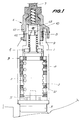
- the disengageable lock comprises, as will be appreciated for example in FIG. 1, a stator 1 and a rotor 2, provided with a known form of guards or flakes 3, and which is capable of turning in the stator when, introduces the appropriate key into the lock, the flakes 3 remain level with the surface of the rotor and they do not remain protruding.
- the rotor has not been shown in section in the figures.
- a socket 4 Between the rotor and the stator is interposed a socket 4, provided with grooves 12 in which the flakes 3 are introduced during the extraction of the key from the lock. So, if rotor 2 is forced to turn with an object other than the correct key, the glitter 3 rotate the sleeve 4.
- the socket 4 according to an important characteristic of the invention, consists of two identical half-sockets, in order to reduce the cost of fabricaction work and simplify assembly.
- the lock further comprises a front head 5, through which the key is introduced, and which is provided as usual with a retractable hatch (not shown) to protect the interior of the lock.
- the rotor 2 is linked in rotation to a latch holder head 6 which in turn supports a latch 7, the rotation of which causes the opening of the lock.
- a torsion spring 8 keeps the lock in an adequate position.
- the latch head 6 has two elements 61 (exterior) and 62 (interior), which are secured by means of a pin 63.
- the union of the rotor with the latch head is such that it allows an axial displacement of the rotor, between a position of rotational coupling with the latch head (engaged position) and a position where the two parts become uncoupled (disengaged position): when the rotor moves axially towards the disengaged position, the rotation of the rotor is not transmitted to the lock.
- the rotor moves to said position when it is caused to rotate with an object other than the correct key.
- the coupling between the rotor 2 and the element 62 of the latch-holder head can be constituted by longitudinal notches A: the rotor carries parts in projection which are introduced into practical complementary housings on the element 62.
- a helical spring 9 is located inside the element 62 of the latch-holder head, so that it remains placed around the rotor 2; it is supported by one of its ends against a rim of the own element 62 and by the other end against a part 10 removably mounted at the end of the rotor.
- the mission of the spring 9 is to maintain the rotor 2 in the engaged position.
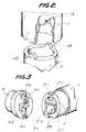
- the rotor 2 and the front head 5 form two separate parts: when the rotor is in the engaged position (shown in Figure 1), there remains a space 11 between the rotor and the front head; however, in order to keep the union in rotation between the two, which can be better understood in FIG. 3, a longitudinal coupling has been provided, consisting here of a projection 5c of the front head, with a complementary housing 2c in the rotor, and a projection 2d of the rotor, with a complementary housing 5d in the front head.
- the front head is provided with two projections 5e, in correspondence with notches 4e made on the socket 4.
- the function of this coupling between the front head and the socket will be described later.
- the socket 4 is mounted inside the stator, so that if the socket is rotated, the union with the stator forces the latter to move axially.
- the socket is provided, at one of its ends, with two longitudinal projections 4b, which are usually (in the disengaged position) housed in corresponding cavities 1b of the stator.
- the projections 4b and the cavities 1b are shaped with corresponding inclined planes, as shown in the figure, so that if the bush is rotated relative to the stator, on the bush acts an axial force component due to the inclined planes of the coupling, which involves the displacement of the socket 4, which moves away from the latch-holder head 6 and approaches the front head 5.
- the flakes 3 do not go back inside the rotor, but they protrude and pass through the grooves of the socket 4.
- the rotor and the socket can remain in an angular position such that the lock remains disengaged, with the socket and the rotor in its axial position closest to the front head.
- the glitter will go backwards, uncoupling the rotor from the socket, which could cause the key to turn the rotor, but without being able to return the socket to its position initial.
- the lock when the correct key is then introduced, it rotates the front head 5, which in turn rotates, on the one hand, the rotor 2 (coupling 5c, 2c and 5d, 2d) and on the other hand, the socket 4 (coupling 5e, 4e), so that after a certain rotation of the key, (180 ° in the most unfavorable case), the bush returns to the position where the projections 4b and the cavities 1b of the stator coincide, the rotor and the sleeve moving axially to return to their normal positions of cooperation with the latch-holder head and the stator, respectively.
- the rotor is provided (FIG. 3) with a rim 2x around the key groove, which is inserted into a complementary notch 5x made around the key head groove 5.
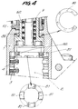
- the lock described can be improved, as or can be seen in FIG. 4, with the arrangement of an open elastic washer 80, between the stator 1 and the internal element 62 of the latch head, which normally recalls the element 62, and therefore the rotor 2 coupled to it, towards the front part of the lock, and with longitudinal projections 81 carried by the rotor, which are free in the normal position of the lock, but if one presses the rotor towards the inside of the lock by deforming the elastic washer 80, are introduced into corresponding notches 82 formed in the socket 4.
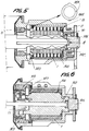
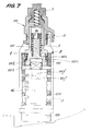
- the first embodiment of the invention can be implemented with a different arrangement of the elements, as can be seen in FIGS. 5 and 6, corresponding to sections through two perpendicular longitudinal planes.
- the rotor 102 and the sleeve 104 are also gyratory, however not being axially mobile; the lock comprises a transmission part 120 integral in rotation with the rotor 102 but able to move axially, and a coupling piece 140 integral in rotation with the sleeve but capable of moving axially.
- the coupling piece 140 shown in perspective in FIG. 8, is provided with longitudinal projections 140b, similar to the projections 4b of the socket of the previous embodiment (FIG. 2), which are normally housed in the cavities 1b of the stator, and which move the part 140 when it is caused to rotate.
- the part 140 is provided with lugs 140f, which form means for securing in rotation the part 140 of the sleeve 104, which allows relative axial displacement.
- the socket 104 has housings 104f complementary to the legs 140f.
- the transmission part 120 is coupled in rotation with the rotor thanks to an axial coupling with square section, formed by a housing 120h of the transmission part and a projection 102h of the rotor, and it cooperates with the lock-holder head of shape similar to that of the coupling A of the previous achievement.
- the rotor 2 has been divided into a rotor 102 (shorter and axially fixed) and a transmission part 120 capable of being moved
- the sleeve 4 has been divided into a sleeve 104 (shorter and axially fixed) and a coupling piece 140 capable of being moved.
- the coupling piece 140 When the coupling piece 140 moves axially, it drives with this movement the transmission piece 120, thanks to the existence of a step 140i, 120i between the two pieces.
- the flakes 3 remain inserted in the grooves 12, driving in rotation the sleeve 104, in a manner analogous to the first embodiment .
- step 140i, 120i the transmission part 120 is driven in the axial direction by the coupling part, thus disengaging the transmission part with respect to the latch head, since the two parts of- coupling A move apart.
- This characteristic allows the front head 105 to be fixed relative to the rotor; if desired, the two elements may be integral, possibly even constituting a single piece.
- the coupling part carries two 140g radial projections in it ( Figure 8) which, when the coupling part moves axially, are inserted in complementary housings (not shown) made in the outer surface of the rotor 102: if the lock is disengaged when the user inserts a correct key, the rotor rotates the coupling piece 140 through these projections 140g, until the projections 140b carried by said part 140 correspond to its complementary cavities 1b of the stator and the lock is again engaged.
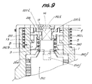
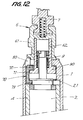
- FIG. 9 shows a variant of the second embodiment of the invention, similarly based on the existence of a transmission part, here made of plastic, between the rotor and the latch head, and a coupling piece between said transmission piece and the socket.
- a transmission part here made of plastic
- the latch head 206 is shorter, and the transmission part 220 cooperates with the head through a coupling A similar to that described in previous embodiments.
- the coupling part 240 in turn has a union with the stator similar to the coupling B of the preceding embodiments (here, 240b with 1b), therefore moving axially when it is caused to rotate, and legs 240f which cooperate with housings 204f carried by the socket 204.
- the rotor 202 and the sleeve 204 are not moved axially, but the disengagement takes place between the transmission part and the latch holder head 206.
- the coupling piece is provided, in order to drive the transmission piece in axial direction, with a transverse shoulder 240i, which cooperates with a flexible longitudinal tongue 220i, in turn provided with a transverse shoulder of the transmission piece .
- the assembly between the two parts is carried out by elastic deformation of the tongue 220i.
- the lock is completed with a washer 13 and a rivet 14, intended to hold the assembled assembly.
- the spring 9 pushes the transmission part 220 towards the latch-holder head 206 in order to keep the lock normally engaged.
- the socket When the appropriate key is used, the socket remains idle, and the rotation is transmitted from the rotor to the transmission part and from this to the latch head.
- the glitter drives the socket with the rotor; in turn, the sleeve drives the coupling part, which is therefore moved in the axial direction and drives the transmission part.
- the movement of the transmission part causes its uncoupling of the latch head, which therefore remains at rest.
- the lock operates in a manner substantially similar to that of the second embodiment described with reference to Figures 7 and 8; the configuration of the elements is, however, different, in order to allow the longitudinal dimensions of the lock to be reduced.
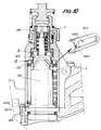
- FIG. 10 illustrates a third embodiment of the lock according to the invention.
- the elements intended to move are the socket 404 and a transmission part 420. Since the rotor 402 does not undergo an axial displacement during disengaging, the socket must be provided with an opening 404v in order to allow its displacement even if the flakes 3 of rotor 402 are not leveled.
- the socket further comprises housings 404e in order to restore the position of the socket by means of the respective projections 402e provided in the rotor after improper use of the lock.
- 402nd mating with 404e is similar to that of 5th with 4th, which has been described with reference to FIG. 3.
- This embodiment has the advantage that the rotor and the front head can be integral and in one piece.
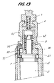
- a longitudinal groove 50 has been made, inside of which is housed at least the body 71 of a blocking or latching element 70, further provided with two wings 72 and 73, so that it has the shape of a C.
- the lock is mounted and in the normal engaged position, shown in FIG. 12, the locking element 70 remains disposed with the wing 73 below a circumferential projection 21 of the rotor 2, and with the wing 72 above a circumferential projection 90 of the internal element 62 of the latch-holder head 6.
- a housing 91 was made in the projection 90, which remains in this position below the wing 72.
- the sleeve 4 rotates, and moves axially, driving the rotor 2.
- the projection 21 then drives the wing 73 of the locking element and, the latter also moves.
- the wing 72 is introduced into the housing 91 of the latch holder head.
- the blocking element being housed also in the groove 50 of the stator as in the housing 91 of the latch-holder head, these two parts cannot undergo mutual rotation; therefore, the lock remains blocked.
- the rotor and the sleeve rotate freely.
- the latch head first turns a small angle, insufficient to open the door, and causes with it the rotor, because they are secured in rotation (clutch engaged); the rotor, however, in turn drives the socket, because in the absence of a key the flakes make the two rotating parts integral, and thanks to the inclined planes described in the first embodiment, the socket moves towards the front part of the lock driving the rotor. This, in turn, causes the locking element to move, which causes the latching head to snap relative to the stator, and therefore the latching head cannot rotate.
- the lock disengages, this disengagement also comprising the actuation of the latching means of the latch head which remains blocked with the stator.
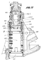
- FIG. 11 represents a fourth embodiment of the disengageable lock according to the present invention.
- the axially movable elements are a transmission part 520 and a coupling part 540, similar to those shown in FIG. 7, but here the axial disengagement movement occurs in an opposite direction, towards the internal part of the lock.
- the transmission part 520 cooperates with rotor 502 through the coupling A, similar to that which has been described in previous embodiments, and communicates the rotation of the rotor 502 to the latch head 506 through a longitudinal longitudinal coupling 520h / 506h.
- the coupling piece 540 is interposed between the piece 520 and the socket assembly 504, with which it cooperates by means of a longitudinal coupling with inclined walls of type B already described.
- the socket 504 rotates in a shape similar to other embodiments; as a result of this rotation the coupling piece 540 is pushed by the union B which it has with the socket towards the rear part of the lock, and it carries with it the transmission piece 520 thanks to the union of 540i shoulder and 520i groove between the two parts.
- the movement of the transmission part produces its declutching with respect to the rotor at A, and consequently the rotor turns freely but it does not carry with it the lock-carrying head.
- This lock also has latching means in order to prevent the opening of the lock acting directly on the latch, these means not needing a separate part and, being produced by means of keys 570 formed in the transmission part 520, and which are introduced into complementary housings 550 of the stator (and prevent the rotation of the part 520 and of the latch-holder head, integral in rotation with said part) when the transmission part towards the inside of the lock.
- the sleeve 504 also initiates rotation, this which causes, as explained, the declutching movement of the part 520 and therefore the locking of the keys 570 in the housings 550.
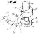
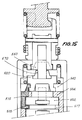
- Figure 15 shows the central part of a lock similar to that of Figure 11, seen in section along a plane perpendicular to the plane of this figure, comprising means for engaging the lock again after improper use.
- a part 515 provided with a tab 516 intended to be housed in a circumferential groove 517 of the rotor 502; this part moves when the lock is disengaged, and it guarantees that the introduction of a correct key into the rotor entails the drive of the socket, and therefore its return to the initial position and to the operability of the lock.
Applications Claiming Priority (2)
| Application Number | Priority Date | Filing Date | Title |
|---|---|---|---|
| ES9302184A ES2073369B1 (es) | 1993-10-08 | 1993-10-08 | Cerradura desembragable para vehiculos y similares. |
| ES9302184 | 1993-10-08 |
Publications (3)
| Publication Number | Publication Date |
|---|---|
| EP0647752A2 true EP0647752A2 (de) | 1995-04-12 |
| EP0647752A3 EP0647752A3 (de) | 1996-05-01 |
| EP0647752B1 EP0647752B1 (de) | 1999-03-31 |
Family
ID=8283353
Family Applications (1)
| Application Number | Title | Priority Date | Filing Date |
|---|---|---|---|
| EP19940500162 Expired - Lifetime EP0647752B1 (de) | 1993-10-08 | 1994-10-05 | Entkuppelbares Schloss für Kraftfahrzeuge und dgl. |
Country Status (3)
| Country | Link |
|---|---|
| EP (1) | EP0647752B1 (de) |
| DE (1) | DE69417499T2 (de) |
| ES (1) | ES2073369B1 (de) |
Cited By (13)
| Publication number | Priority date | Publication date | Assignee | Title |
|---|---|---|---|---|
| EP0769597A1 (de) * | 1995-10-18 | 1997-04-23 | Valeo Securite Habitacle | Schloss vom Typ eines entkuppelbaren Rotors |
| EP0806531A1 (de) * | 1996-05-10 | 1997-11-12 | Valeo Securite Habitacle | Axial (ent)kuppelndes Schloss für ein Schlossmechanismus eines Personenkraftwagens |
| WO1999030320A1 (en) * | 1997-12-09 | 1999-06-17 | Storage Technology Corporation | A break away lever for a tape drive handle |
| EP0943758A1 (de) * | 1998-03-17 | 1999-09-22 | Valeo Securite Habitacle | Axial entkuppelndes Schloss für ein Schlossmechanismus eines Personenkraftwagens |
| EP1052351A2 (de) * | 1999-05-13 | 2000-11-15 | Rover Group Limited | Verriegelungsvorrichtung für Kraftfahrzeug |
| EP1077300A1 (de) * | 1999-08-19 | 2001-02-21 | ABUS August Bremicker Söhne KG | Schloss mit Zylinderschutz |
| WO2001038672A1 (en) * | 1999-11-26 | 2001-05-31 | Giobert S.P.A. | A cylinder lock with a security device |
| WO2005035914A1 (de) * | 2003-10-09 | 2005-04-21 | Huf Hülsbeck & Fürst Gmbh & Co.Kg | Schliesszylinder für ein schloss, insbesondere bei fahrzeugen |
| FR2895762A1 (fr) * | 2005-12-30 | 2007-07-06 | Valeo Securite Habitacle Sas | Verrou debrayable pour un mecanisme de serrure automobile |
| WO2011057626A1 (de) * | 2009-11-10 | 2011-05-19 | Huf Hülsbeck & Fürst Gmbh & Co. Kg | Schliesszylinder |
| WO2011047675A3 (de) * | 2009-10-22 | 2011-06-23 | Huf Hülsbeck & Fürst Gmbh & Co. Kg | Schliesszylinder |
| WO2012059094A1 (de) * | 2010-10-08 | 2012-05-10 | Huf Hülsbeck & Fürst Gmbh & Co. Kg | Schliesszylinder |
| ITTO20110192A1 (it) * | 2011-03-03 | 2012-09-04 | Giobert Spa | Serratura provvista di un sistema anti-effrazione per una porta di un veicolo |
Families Citing this family (1)
| Publication number | Priority date | Publication date | Assignee | Title |
|---|---|---|---|---|
| CN208073175U (zh) * | 2018-02-08 | 2018-11-09 | 长园共创电力安全技术股份有限公司 | 轴向式离合解闭锁机构的连接结构 |
Citations (4)
| Publication number | Priority date | Publication date | Assignee | Title |
|---|---|---|---|---|
| EP0212468A1 (de) * | 1985-08-08 | 1987-03-04 | Tomio Oota | Zylinderschloss |
| EP0341132A1 (de) * | 1988-05-04 | 1989-11-08 | Valeo Neiman | Verriegelung mit entkuppelbarem Rotor |
| FR2635351A1 (fr) * | 1988-08-12 | 1990-02-16 | Daimler Benz Ag | Cylindre de fermeture, notamment pour serrure de porte de vehicule |
| DE4122414C1 (de) * | 1991-07-06 | 1992-12-03 | Huelsbeck & Fuerst | Schließzylinder |
-
1993
- 1993-10-08 ES ES9302184A patent/ES2073369B1/es not_active Expired - Fee Related
-
1994
- 1994-10-05 EP EP19940500162 patent/EP0647752B1/de not_active Expired - Lifetime
- 1994-10-05 DE DE1994617499 patent/DE69417499T2/de not_active Expired - Fee Related
Patent Citations (4)
| Publication number | Priority date | Publication date | Assignee | Title |
|---|---|---|---|---|
| EP0212468A1 (de) * | 1985-08-08 | 1987-03-04 | Tomio Oota | Zylinderschloss |
| EP0341132A1 (de) * | 1988-05-04 | 1989-11-08 | Valeo Neiman | Verriegelung mit entkuppelbarem Rotor |
| FR2635351A1 (fr) * | 1988-08-12 | 1990-02-16 | Daimler Benz Ag | Cylindre de fermeture, notamment pour serrure de porte de vehicule |
| DE4122414C1 (de) * | 1991-07-06 | 1992-12-03 | Huelsbeck & Fuerst | Schließzylinder |
Cited By (25)
| Publication number | Priority date | Publication date | Assignee | Title |
|---|---|---|---|---|
| FR2740163A1 (fr) * | 1995-10-18 | 1997-04-25 | Valeo Securite Habitacle | Verrou du type a rotor debrayable |
| EP0769597A1 (de) * | 1995-10-18 | 1997-04-23 | Valeo Securite Habitacle | Schloss vom Typ eines entkuppelbaren Rotors |
| EP0806531A1 (de) * | 1996-05-10 | 1997-11-12 | Valeo Securite Habitacle | Axial (ent)kuppelndes Schloss für ein Schlossmechanismus eines Personenkraftwagens |
| FR2748513A1 (fr) * | 1996-05-10 | 1997-11-14 | Valeo Securite Habitacle | Verrou a debrayage axial pour un mecanisme de serrure de vehicule automobile |
| US5732580A (en) * | 1996-05-10 | 1998-03-31 | Valeo Securite Habitacle | Axially disengageable lock for a motor vehicle locking system |
| US5991117A (en) * | 1996-05-14 | 1999-11-23 | Storage Technology Corporation One Storage Tek Drive | Break away lever for a tape drive handle |
| US6160681A (en) * | 1996-05-14 | 2000-12-12 | Storage Technology Corporation | Method for preventing excessive force exerted on a lever assembly |
| WO1999030320A1 (en) * | 1997-12-09 | 1999-06-17 | Storage Technology Corporation | A break away lever for a tape drive handle |
| EP0943758A1 (de) * | 1998-03-17 | 1999-09-22 | Valeo Securite Habitacle | Axial entkuppelndes Schloss für ein Schlossmechanismus eines Personenkraftwagens |
| FR2776325A1 (fr) * | 1998-03-17 | 1999-09-24 | Valeo Securite Habitacle | Verrou a debrayage axial perfectionne pour un mecanisme de serrure de vehicule automobile |
| EP1052351A2 (de) * | 1999-05-13 | 2000-11-15 | Rover Group Limited | Verriegelungsvorrichtung für Kraftfahrzeug |
| EP1052351A3 (de) * | 1999-05-13 | 2001-10-04 | Bayerische Motoren Werke Aktiengesellschaft | Verriegelungsvorrichtung für Kraftfahrzeug |
| EP1077300A1 (de) * | 1999-08-19 | 2001-02-21 | ABUS August Bremicker Söhne KG | Schloss mit Zylinderschutz |
| WO2001038672A1 (en) * | 1999-11-26 | 2001-05-31 | Giobert S.P.A. | A cylinder lock with a security device |
| WO2005035914A1 (de) * | 2003-10-09 | 2005-04-21 | Huf Hülsbeck & Fürst Gmbh & Co.Kg | Schliesszylinder für ein schloss, insbesondere bei fahrzeugen |
| FR2895762A1 (fr) * | 2005-12-30 | 2007-07-06 | Valeo Securite Habitacle Sas | Verrou debrayable pour un mecanisme de serrure automobile |
| WO2007077345A2 (fr) * | 2005-12-30 | 2007-07-12 | Valeo Securite Habitacle | Verrou debrayable pour un mecanisme de serrure automobile |
| WO2007077345A3 (fr) * | 2005-12-30 | 2007-09-13 | Valeo Securite Habitacle | Verrou debrayable pour un mecanisme de serrure automobile |
| CN101384785B (zh) * | 2005-12-30 | 2012-07-04 | 法雷奥安全座舱公司 | 用于车辆锁定机构的自动脱离的锁 |
| WO2011047675A3 (de) * | 2009-10-22 | 2011-06-23 | Huf Hülsbeck & Fürst Gmbh & Co. Kg | Schliesszylinder |
| WO2011057626A1 (de) * | 2009-11-10 | 2011-05-19 | Huf Hülsbeck & Fürst Gmbh & Co. Kg | Schliesszylinder |
| US9506273B2 (en) | 2009-11-10 | 2016-11-29 | Huf Hulsbeck & Furst Gmbh & Co. Kg | Lock cylinder |
| US9745774B2 (en) | 2009-11-10 | 2017-08-29 | Huf Husbeck & Furst Gmbh & Co. Kg | Lock cylinder |
| WO2012059094A1 (de) * | 2010-10-08 | 2012-05-10 | Huf Hülsbeck & Fürst Gmbh & Co. Kg | Schliesszylinder |
| ITTO20110192A1 (it) * | 2011-03-03 | 2012-09-04 | Giobert Spa | Serratura provvista di un sistema anti-effrazione per una porta di un veicolo |
Also Published As
| Publication number | Publication date |
|---|---|
| DE69417499D1 (de) | 1999-05-06 |
| DE69417499T2 (de) | 1999-09-23 |
| ES2073369R (de) | 1998-04-01 |
| ES2073369B1 (es) | 1999-06-16 |
| EP0647752A3 (de) | 1996-05-01 |
| EP0647752B1 (de) | 1999-03-31 |
| ES2073369A2 (es) | 1995-08-01 |
Similar Documents
| Publication | Publication Date | Title |
|---|---|---|
| EP0806531B1 (de) | Axial (ent)kuppelndes Schloss für ein Schlossmechanismus eines Personenkraftwagens | |
| EP2611656B1 (de) | Lenkungsverriegelung für ein kraftfahrzeug | |
| EP0647752A2 (de) | Entkuppelbares Schloss für Kraftfahrzeuge und dgl. | |
| WO1999061728A1 (fr) | Serrure electronique a embrayage mecanique | |
| EP2201200B1 (de) | Drehbarer schlüssel mit verstärkter rastung zur betätigung eines schlosses | |
| EP1859113A1 (de) | Lösbarer verschluss für ein verschlusssystem eines kraftfahrzeugs | |
| EP1580358A1 (de) | Schutz für Verstellvorrichtung zur Verschlussbetätigung mittels eines Schlosses | |
| EP0140740B1 (de) | Sicherheitsschloss | |
| EP0943758B1 (de) | Axial entkuppelndes Schloss für ein Schlossmechanismus eines Personenkraftwagens | |
| WO1999036838A1 (fr) | Dispositif de fixation rapide pour montre-bracelet | |
| EP0520904B1 (de) | Verriegelung mit entkuppelbarem Rotor | |
| FR2614921A1 (fr) | Dispositif de securite a l'arrachement et a l'enfoncement d'une piece emmanchee dans une autre piece, et ensemble formant serrure de surete equipe de ce dispositif | |
| EP2614201A1 (de) | Schubriegelschloss für ein verriegelungssystem eines kraftfahrzeugs | |
| EP2960406A1 (de) | Vorrichtung zum öffnen und schliessen eines artikels, insbesondere eines lederwaren-artikels, und artikel, der eine solche vorrichtung umfasst | |
| EP0879927B1 (de) | Verbesserte Rastleiste für Zuhaltungslamellen eines am Auto montierten Zylinderschlosses | |
| EP1927710B1 (de) | Ausschaltbares Schloss für Schließmechanismus eines Kraftfahrzeugs | |
| EP0628455A1 (de) | Lenkradschloss für Kraftfahrzeug | |
| FR2552146A1 (fr) | Serrure de surete | |
| FR2775716A1 (fr) | Cylindre de surete a barillet double | |
| EP3599146B1 (de) | Anschlusshaken für spoiler | |
| EP0869236B1 (de) | Von einer Seite aus betätigbarer Sicherheitszylinder selbst wenn ein Schlüssel auf der anderen Seite eingesteckt ist | |
| EP3384113B1 (de) | Schloss für einen fahrzeugverriegelungsmechanismus | |
| FR2755173A1 (fr) | Verrou a autocodage | |
| EP0443896A1 (de) | Verschluss mit einem Stator, in welchem ein um mindestens einen Winkelbereich drehbarer, mit einem Mitnehmer rotationsverbundener Rotor angeordnet ist | |
| EP3658724A1 (de) | Sicherheitsschloss und flachschlüsselanordnung |
Legal Events
| Date | Code | Title | Description |
|---|---|---|---|
| PUAI | Public reference made under article 153(3) epc to a published international application that has entered the european phase |
Free format text: ORIGINAL CODE: 0009012 |
|
| AK | Designated contracting states |
Kind code of ref document: A2 Designated state(s): DE FR GB IT |
|
| PUAL | Search report despatched |
Free format text: ORIGINAL CODE: 0009013 |
|
| AK | Designated contracting states |
Kind code of ref document: A3 Designated state(s): DE FR GB IT |
|
| 17P | Request for examination filed |
Effective date: 19960827 |
|
| 17Q | First examination report despatched |
Effective date: 19970619 |
|
| GRAG | Despatch of communication of intention to grant |
Free format text: ORIGINAL CODE: EPIDOS AGRA |
|
| GRAG | Despatch of communication of intention to grant |
Free format text: ORIGINAL CODE: EPIDOS AGRA |
|
| GRAH | Despatch of communication of intention to grant a patent |
Free format text: ORIGINAL CODE: EPIDOS IGRA |
|
| GRAH | Despatch of communication of intention to grant a patent |
Free format text: ORIGINAL CODE: EPIDOS IGRA |
|
| GRAA | (expected) grant |
Free format text: ORIGINAL CODE: 0009210 |
|
| AK | Designated contracting states |
Kind code of ref document: B1 Designated state(s): DE FR GB IT |
|
| REF | Corresponds to: |
Ref document number: 69417499 Country of ref document: DE Date of ref document: 19990506 |
|
| ITF | It: translation for a ep patent filed |
Owner name: SOCIETA' ITALIANA BREVETTI S.P.A. |
|
| GBT | Gb: translation of ep patent filed (gb section 77(6)(a)/1977) |
Effective date: 19990415 |
|
| PLBE | No opposition filed within time limit |
Free format text: ORIGINAL CODE: 0009261 |
|
| STAA | Information on the status of an ep patent application or granted ep patent |
Free format text: STATUS: NO OPPOSITION FILED WITHIN TIME LIMIT |
|
| 26N | No opposition filed | ||
| REG | Reference to a national code |
Ref country code: GB Ref legal event code: IF02 |
|
| PGFP | Annual fee paid to national office [announced via postgrant information from national office to epo] |
Ref country code: GB Payment date: 20050923 Year of fee payment: 12 |
|
| PGFP | Annual fee paid to national office [announced via postgrant information from national office to epo] |
Ref country code: DE Payment date: 20051007 Year of fee payment: 12 |
|
| PGFP | Annual fee paid to national office [announced via postgrant information from national office to epo] |
Ref country code: FR Payment date: 20051028 Year of fee payment: 12 |
|
| PGFP | Annual fee paid to national office [announced via postgrant information from national office to epo] |
Ref country code: IT Payment date: 20061031 Year of fee payment: 13 |
|
| PG25 | Lapsed in a contracting state [announced via postgrant information from national office to epo] |
Ref country code: DE Free format text: LAPSE BECAUSE OF NON-PAYMENT OF DUE FEES Effective date: 20070501 |
|
| GBPC | Gb: european patent ceased through non-payment of renewal fee |
Effective date: 20061005 |
|
| REG | Reference to a national code |
Ref country code: FR Ref legal event code: ST Effective date: 20070629 |
|
| PG25 | Lapsed in a contracting state [announced via postgrant information from national office to epo] |
Ref country code: GB Free format text: LAPSE BECAUSE OF NON-PAYMENT OF DUE FEES Effective date: 20061005 |
|
| PG25 | Lapsed in a contracting state [announced via postgrant information from national office to epo] |
Ref country code: FR Free format text: LAPSE BECAUSE OF NON-PAYMENT OF DUE FEES Effective date: 20061031 |
|
| PG25 | Lapsed in a contracting state [announced via postgrant information from national office to epo] |
Ref country code: IT Free format text: LAPSE BECAUSE OF NON-PAYMENT OF DUE FEES Effective date: 20071005 |