EP4497586A1 - Behälter für plattform mit verdichtungsschaufel - Google Patents
Behälter für plattform mit verdichtungsschaufel Download PDFInfo
- Publication number
- EP4497586A1 EP4497586A1 EP24190444.0A EP24190444A EP4497586A1 EP 4497586 A1 EP4497586 A1 EP 4497586A1 EP 24190444 A EP24190444 A EP 24190444A EP 4497586 A1 EP4497586 A1 EP 4497586A1
- Authority
- EP
- European Patent Office
- Prior art keywords
- shovel
- compaction
- container
- roof
- box
- Prior art date
- Legal status (The legal status is an assumption and is not a legal conclusion. Google has not performed a legal analysis and makes no representation as to the accuracy of the status listed.)
- Granted
Links
Images

Classifications
-
- B—PERFORMING OPERATIONS; TRANSPORTING
- B30—PRESSES
- B30B—PRESSES IN GENERAL
- B30B9/00—Presses specially adapted for particular purposes
- B30B9/30—Presses specially adapted for particular purposes for baling; Compression boxes therefor
- B30B9/3042—Containers provided with, or connectable to, compactor means
- B30B9/3046—Containers with built-in compactor means
-
- B—PERFORMING OPERATIONS; TRANSPORTING
- B30—PRESSES
- B30B—PRESSES IN GENERAL
- B30B9/00—Presses specially adapted for particular purposes
- B30B9/30—Presses specially adapted for particular purposes for baling; Compression boxes therefor
- B30B9/3082—Presses specially adapted for particular purposes for baling; Compression boxes therefor with compression means other than rams performing a rectilinear movement
-
- B—PERFORMING OPERATIONS; TRANSPORTING
- B65—CONVEYING; PACKING; STORING; HANDLING THIN OR FILAMENTARY MATERIAL
- B65F—GATHERING OR REMOVAL OF DOMESTIC OR LIKE REFUSE
- B65F1/00—Refuse receptacles; Accessories therefor
- B65F1/02—Refuse receptacles; Accessories therefor without removable inserts
-
- B—PERFORMING OPERATIONS; TRANSPORTING
- B65—CONVEYING; PACKING; STORING; HANDLING THIN OR FILAMENTARY MATERIAL
- B65F—GATHERING OR REMOVAL OF DOMESTIC OR LIKE REFUSE
- B65F1/00—Refuse receptacles; Accessories therefor
- B65F1/14—Other constructional features; Accessories
- B65F1/1405—Compressing means incorporated in, or specially adapted for, refuse receptacles
Definitions
- the invention relates to a compaction shovel container.
- the counting means may be arranged in the container at a first end thereof and comprise a wall pressing the waste against a second end thereof.
- One aim of the invention is to propose a solution making it possible to compress bulky and/or heavy and/or difficult to deform waste.
- the handling means include two groups of at least three jacks.
- the two groups are arranged on the roof symmetrically with respect to the center of the roof.
- the first cylinder is able to develop a greater thrust than the second cylinder or the third cylinder.
- the first cylinder is arranged between the second cylinder and the third cylinder.
- the second cylinder and the third cylinder are identical.
- the balancer has two arms, each of the arms being articulated relative to the shovel on the one hand and relative to the roof on the other hand.
- the arms are articulated on the roof symmetrically with respect to the center of the roof and/or are articulated relative to the shovel symmetrically with respect to the center of the roof.
- the balance is articulated on the shovel by means of at least one connecting rod.
- At least a portion of the balance is bent.
- the container includes a slide extending between an upper end of the box and the interior of the box to form a slope toward the interior of the box.
- FIGS 1 to 4 represent a waste disposal site comprising at least one waste disposal site quay Q overlooking at least one container 1 also called storage container 1.
- quay Q is located between 0.2 and 1 meter above a roof 2 of container 1.
- a safety barrier B secures dock Q so that a user cannot fall into container 1 or be injured by the movement of a compacting shovel for container 1, which will be described below.
- the container 1 comprises a box 3 comprising a frame formed of sides, the frame being entirely closed at the lower end by a bottom 4.
- the sides are here four in number.
- the sides and/or the bottom 4 are formed of sheets. The sides and/or the bottom 4 are fixed together.
- the container 1 is generally shaped like a parallelepiped.
- the container 1 thus extends longitudinally in a first direction X.
- the bottom 4 extends parallel to a plane containing the first direction X and a second direction Y orthogonal to the first direction X.
- Two of the four sides extend parallel to a plane containing the X and Z axes and are hereinafter called longitudinal sides.
- the other two sides of the box 3 extend parallel to a plane containing the Y and Z axes and are hereinafter called lateral sides.
- a first lateral side 5 forms or comprises a door allowing access to the interior of the box 3.
- box 3 This allows box 3 to be emptied when it is taken, for example, to an incineration or recycling plant.
- Box 3 also includes a roof 2 arranged at the upper end of box 1.
- the base 6 extends over only part of the length of the box 3 (in the first direction X) and over the entire width of the box 3 on this part considered (in the second direction Y).
- the base 6 thus partially closes the upper end of the box 3. It defines an opening 7 for access to the interior of the box 3.
- This opening 7 is arranged at a first longitudinal end of the box 3.
- Container 1 is further arranged so that the first longitudinal end of box 3 is located opposite platform Q and below it. Container 1 thus extends orthogonally to platform Q. Opening 7 is therefore located directly under platform Q.
- the second lateral flank 8 (forming the first longitudinal end of the box 3) is located opposite platform Q and opposite the first lateral flank 5.
- the access door to the interior of container 3 is located on a flank opposite that associated with opening 7 and platform Q.
- the roof 2 also comprises a compaction shovel 9 mounted on the roof 2 and more particularly mounted on the upper face 6a of the base 6 (i.e. the face opposite the lower face 6b of the base 6 which is turned towards the inside of the box 3).
- the compaction shovel 9 is thus fixed to the rest of the container 3.
- the compaction shovel 9 is movably mounted on the base 2 between a high position and a low position.
- the compaction shovel 9 is preferably mounted to be able to rotate between these two high and low positions around a shaft 10 extending along an axis A.
- the compaction shovel 9 is mounted on the base 6 so that the axis A is parallel to the second direction Y.
- the compaction shovel 9 is mounted on the base 6 so that the shaft 10 extends along the edge of the base 6 defining the opening 7.
- the compaction shovel 9 is arranged at the first longitudinal end of the box 3 while the access door is located at the second longitudinal end of the box 3.
- the access door and the compaction shovel 9 are thus arranged at opposite ends of the box 3.
- the roof 2 also includes means for moving the compaction shovel 9 between its high position and its low position.
- the moving means comprise a balance 11 articulated on the compaction shovel 9 on the one hand and on the base 6 on the other hand.
- the balance 11 comprises a plate 12 and at least one arm.
- the plate 12 is associated with two arms 13 and 14 of the balance 11.
- the plate 12 and the two arms 13, 14 are made of a single piece.
- each arm 13, 14 is arranged at one of the lateral ends of the balance 11.
- the plate 12 thus forms a spacer between the two arms 13, 14.
- Each arm 13, 14 is here bent.
- Each arm 13, 14 is optionally formed of two connecting rods (which are however preferably in one piece): a first connecting rod 15 extends along an axis C and a second connecting rod 16 extends along an axis D, the axis D being inclined with respect to the axis C.
- the two arms 13, 14 are arranged identically so that the two first connecting rods 15 extend parallel to each other and to the axis C and the two second connecting rods 16 extend parallel to each other and to the axis D.
- the two arms 13, 14 are thus arranged so that the first connecting rods 15 are articulated at their first end on the base 6 along the same articulation axis E (but in two different zones of the base 6 given the spacing between the two arms 13, 14).
- the first connecting rods 15 are articulated on the base symmetrically relative to the center of the base 6.
- the first connecting rods 15 are directly articulated on the base 6.
- the two arms 13, 14 are furthermore arranged so that the second ends of the first connecting rods 15 coincide with the first ends of the second connecting rods 16.
- the two arms 13, 14 are furthermore arranged so that the second ends of the second connecting rods 16 are articulated at their second end on the compaction shovel 9 along the same axis F (but in two different zones of the compaction shovel 9 given the spacing between the two arms 13, 14).
- the second connecting rods 16 are not mounted directly in an articulated manner on the compaction shovel 9 but are directly articulated on connecting rods which are themselves directly mounted in an articulated manner on the compaction shovel 9.
- first arm 13 its second connecting rod 16 is mounted articulated at its second end to a first end of a first connecting rod 17 along the axis F, the first connecting rod 17 itself being mounted articulated at its second end on the compaction shovel 9 along an axis G.
- its second connecting rod 16 is mounted articulated at its second end to a first end of a second connecting rod 18 along the axis F, the second connecting rod itself being mounted articulated at its second end on the compaction shovel 9 along the axis G.
- the second connecting rods 17, 18 are articulated on the compaction shovel 9 symmetrically relative to the center of the compaction shovel 9.
- the second connecting rods 17, 18 are articulated on the first main face 9b of the compaction shovel 9.
- the F and G axes are here parallel to each other.
- the F and E axes are here parallel to each other.
- At least one of the axes E, F, G is parallel to the second direction Y and/or to the axis A.
- the roof 6 comprises means for manipulating the balance 11.
- the handling means here comprise a first group 19 of at least three jacks and a second group 20 of at least three jacks.
- the two groups 19, 20 being identical in the present case, the following description of the first group 19 is also applicable to the second group 20.
- the first group 19 comprises three jacks, namely a central jack 21 and two lateral jacks 22, 23 arranged on either side of the central jack 21.
- the lateral jacks 22, 23 are for example fixed to the central jack 21 or removably secured to the central jack 21. More preferably, the lateral jacks 22, 23 are fixed to the central jack 21 while being arranged symmetrically relative to the central jack 21.
- the two lateral cylinders 22, 23 are arranged so as to be each articulated at a first of their ends on the base 6 along the same articulation axis H (but in two different zones of the base 6 given the spacing between the two lateral cylinders 22, 23). Their second ends are integral with the central cylinder 21.
- the lateral cylinders 22, 23 are thus able to deploy/retract simultaneously in the direction of the base 6.
- central cylinder 21 is arranged so as to be articulated at a first of its ends on the balance 11 along an articulation axis I. Its second end is secured to the lateral cylinders 22, 23.
- the central cylinder 21 is articulated on an intermediate zone of the balance 11 outside the first ends of the first connecting rods 15 and outside the second ends of the second connecting rods 16.
- the intermediate zone is the bent zone 24 of the balance 11 (i.e. the portion of the balance 11 defined by the bends of the two arms 13, 14 and the possible bend of the plate 12).
- the central cylinder 21 is articulated to the second end of the first connecting rod 15 (which coincides with the first end of the second connecting rod 16). The central cylinder 21 is thus able to deploy/retract in the direction of the compaction shovel 9.
- At least one of the I and H axes is parallel to the second Y direction and/or the A axis.
- the lateral cylinders 22, 23 are mounted in an inverted manner with respect to the central cylinder 21 so that they deploy/retract opposite the base 6 unlike the central cylinder 21 which deploys/retracts in the direction of the balance 11.
- the assembly of the cylinders is such that the rods of the two lateral cylinders 22, 23 and of the central cylinder 21 retract and unfold parallel to each other (but in opposite directions as seen above).
- the pressurized fluid supply to the cylinders is provided by at least one fluid supply source and at least one associated distribution circuit (not shown).
- the two lateral cylinders 22, 23 are preferably identical to each other.
- the two lateral cylinders 22, 23 thus develop the same thrust.
- the central cylinder 21 develops a thrust identical to the sum of the thrusts of the two lateral cylinders 22, 23.
- the central cylinder 21 develops a thrust at least greater than 15 tonnes and preferably at least greater than 20 tonnes.
- each of the lateral cylinders 22, 23 develops a thrust at least greater than 5 tonnes and preferably at least greater than 10 tonnes.
- the group of three cylinders develops an overall thrust of at least 40 tonnes and preferably at least 45 tonnes.
- the base 6 includes side members 25 and cross bars 26 to reinforce the base 6.
- the articulation zones of the first connecting rods 15 on the base 6 are located on the side members 25 or the cross bars 26.
- the articulation zones of the first ends of the lateral cylinders 22, 23 on the base 6 are located on the side members 25 or the cross bars 26.
- the container 1 comprises a slide 27 to facilitate the compaction of the waste.
- This slide 27 is here associated with the first longitudinal end of the box 3.
- the slide 27 is directly formed by the second lateral flank 8 (and possibly one or more other adjacent flanks and/or the bottom 4) and/or one or more additional walls fixed to the second lateral flank 8 (and possibly one or more other adjacent flanks and/or the bottom 4).
- the slide 27 preferably comprises at least a first zone forming a slope 28 in the direction of inside the box 3.
- Such a slope 28 makes it easier for the waste to fall inside the box 3, in particular by preventing the waste from being stored at the level of the second lateral flank 8.
- the slope 28 extends from the upper end of the box 3 to the inside of the box 3 towards the first lateral flank 5 and/or the bottom 4 of the box 3.
- the slope 28 is not flat.
- the slope 28 is thus curved towards the bottom 4 and/or the second lateral flank 8.
- the slope 28 thus draws an arc of a circle.
- the curvature of the slope 28 matches the rotation path of a free end of the compaction shovel 9.
- the slope 28 extends from the upper end of the box 3 to the level of the articulation shaft 10.
- the slide 27 preferably comprises at least one second zone 29 extending successively to the first zone to connect the first zone to the bottom 4 of the box 3.
- the second zone 29 extends in a rectilinear manner between the first zone and the bottom 4 of the box 3.
- This second zone 29 advantageously prevents waste from accumulating up the slope. This frees up the opening 7.
- the second zone 29 extends for example parallel to the second lateral flank 8 and/or vertically.
- the slide 27 thus described is fixed in the container 1 and partly shaped into an arc of a circle which follows the trajectory of the end of the shovel, in order to guide the waste being compacted/compacted towards the rear of the container 1 and to prevent the compaction shovel 9 from falling on a wall of non-compactable and/or non-compacted waste.
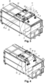
- the container 1 is such that the compaction shovel 9 is in the high position as illustrated in figure 1 and to the figure 2 .
- This high position is also called the “loading position”.
- the opening 7 is freely accessible, thus allowing a user to unload their waste into the container 1.
- the bent zone 24 is directed towards the base 6 while being arranged at the rear of the axes E, F, G and A and at the front of the axis H. From the front to the rear (the front being defined as being the part of the container 1 closest to the dock Q and the rear as being the part of the container 1 furthest from the dock Q, the first longitudinal end of the box 3 is thus at the front of the container 1 and the second longitudinal end of the box 3 is thus at the rear of the container 1), the following axes are thus successively found: A, G, F, E, I and H.
- container 1 is then open since opening 7 is not covered by roof 2 and in particular by compaction shovel 9: a user can thus tip waste inside container 1 via opening 7.
- the opening 7 proves to be of particularly large dimensions since the compaction shovel 9 defines with the base 6 an angle optionally between 80 and 100 degrees, and for example between 85 and 95 degrees, and for example between 88 and 92 degrees and is for example 90 degrees, while being arranged outside the box 3. This greatly facilitates the loading of waste into the container 1 even if the waste is of large dimensions.
- the compaction shovel 9 must be tilted into its lower position.
- the cylinders are then actuated to lower the compaction shovel 9. This actuation can be done automatically (for example at regular time intervals, when new waste is detected being tipped into the container 1, etc.) or manually by a waste disposal center operator.
- the dimensions of the compaction shovel 9 are such that it is not in contact with the longitudinal flanks during its movement between its high position and its low position.
- the compaction shovel 9 passes through a neutral position, visible at the figure 3 , during its movement from high position to low position (and vice versa).
- the rods of the central cylinders 21 are here deployed between the high position and the neutral position.
- the rods of the lateral cylinders 22, 23 are optionally not deployed and are therefore in the same position relative to the body of the associated cylinder whether in the high position or in the neutral position (and the intermediate positions between the two).
- the rods of the central cylinders 21 are fully deployed or at least partially deployed in the neutral position.
- the bent zone 24 is directed towards the second longitudinal end of the box 3, being arranged at the rear of the axes E, F, G and A and at the front of the axis H. From front to rear, the following axes are thus successively found: G, F, A, E, I and H. If the plate 12 comprises a part extending between the two second connecting rods 16 of the balance 11, then this part extends here parallel to the base 6 and optionally parallel to the first direction X.
- the compaction shovel 9 extends in line with the base 6.
- the compaction shovel 9 thus extends at the level of the base 6.
- the compaction shovel 9 is more particularly arranged parallel to the base 6 and optionally parallel to the first direction X and optionally parallel to the part of the rocker arm 11 extending between the two second connecting rods 16.
- the container 1 is then closed. Indeed, the compaction shovel 9 then covers the opening 7. More precisely, the compaction shovel 9 forms a junction between the base 6 and the first longitudinal end of the box 3.
- the neutral position is also called “transport position or safety position (especially against theft)”.
- the compaction shovel 9 continues its movement towards its lower position visible at the figure 4 also called “compaction position”.
- the rods of the lateral cylinders 22, 23 are here deployed.
- the rods of the central cylinders 21 are optionally not deployed and are therefore in the same position relative to the body of the associated cylinder whether in the low position or in the neutral position (and the intermediate positions between the two).
- the rods of the lateral cylinders 22, 23 are fully deployed or at least partially deployed in the low position.
- the bent zone 24 is directed upwards (in the opposite direction from the inside of the box 3) and is arranged at the rear of the axes A, G and F and at the front of the axes E and H. From front to rear, we thus find successively the following axes: F, G, A, I, E and H.
- the compaction shovel 9 extends inside the box 3.
- the compaction shovel 9 is thus engaged in the box 3, which allows it to compact the waste.
- the opening of the box 3 allows the compaction shovel 9 to be able to switch from its high position to its low position to fit inside the box 3.
- the compaction shovel 9 then defines with the base 6 an angle optionally between 80 and 100 degrees, and for example between 85 and 95 degrees, and for example between 88 and 92 degrees and is for example 90 degrees, while being arranged inside the box 3.
- the movement of the compaction shovel 9 is continuous between its high position and its low position without stopping at the neutral position. Similarly, the return of the compaction shovel 9 to its high position is done without stopping at the neutral position.
- the compaction shovel 9 can be brought into its neutral position and kept in this position.
- the container 1 thus described has a very large opening when the compaction shovel 9 is in its high position.
- the container 1 thus described allows a large movement of the compaction shovel 9.
- the actuating means advantageously allow the compaction shovel 9 to be able to carry out such a movement while themselves presenting a relatively limited movement.
- the compaction shovel may have side members and/or cross bars for reinforcement.
- the base may not have side members and/or cross bars.
- the balance may be articulated in only one zone (and not two as indicated) on the base on the one hand and/or on the compaction shovel on the other hand or may be articulated on a greater number of zones than one or two on the base on the one hand and/or on the compaction shovel on the other hand.
- the pendulum may be manipulated in only one zone (and not two as indicated) by the manipulation means or may be manipulated in a greater number of zones than indicated.
- the container can be arranged in bottom of a dock in a company, a logistics warehouse or others ... or be arranged at the level of a dock or in an intermediate part between the level of the dock and under the dock.
- the intermediate area of the balance may not be bent.
- the container may have a shape other than that indicated.
- the base and bottom of the container may not be parallel to each other.
- the container may not have a parallelepiped shape but a conical shape.
- the compaction shovel may be shaped differently from what has been indicated: for example, the compaction shovel may not be shaped like a plate and/or may not have two main faces that extend parallel to each other.
Landscapes
- Engineering & Computer Science (AREA)
- Mechanical Engineering (AREA)
- Refuse Collection And Transfer (AREA)
- Processing Of Solid Wastes (AREA)
Applications Claiming Priority (1)
| Application Number | Priority Date | Filing Date | Title |
|---|---|---|---|
| FR2308142A FR3151529B1 (fr) | 2023-07-27 | 2023-07-27 | Conteneur à pelle de compaction |
Publications (2)
| Publication Number | Publication Date |
|---|---|
| EP4497586A1 true EP4497586A1 (de) | 2025-01-29 |
| EP4497586B1 EP4497586B1 (de) | 2026-03-25 |
Family
ID=88965659
Family Applications (1)
| Application Number | Title | Priority Date | Filing Date |
|---|---|---|---|
| EP24190444.0A Active EP4497586B1 (de) | 2023-07-27 | 2024-07-23 | Behälter für plattform mit verdichtungsschaufel |
Country Status (2)
| Country | Link |
|---|---|
| EP (1) | EP4497586B1 (de) |
| FR (1) | FR3151529B1 (de) |
Citations (4)
| Publication number | Priority date | Publication date | Assignee | Title |
|---|---|---|---|---|
| FR2219088A2 (de) * | 1973-02-27 | 1974-09-20 | Peltier Raymond | |
| DE2944307A1 (de) * | 1979-11-02 | 1981-05-07 | Fa. Werner Kähler, 2246 Norderheistedt | Muellpresse |
| FR2945284A1 (fr) * | 2009-05-07 | 2010-11-12 | Gillard Sas G | Benne de collecte de dechets |
| US10974896B1 (en) * | 2020-07-07 | 2021-04-13 | Broyhill, Inc. | Refuse hopper |
-
2023
- 2023-07-27 FR FR2308142A patent/FR3151529B1/fr active Active
-
2024
- 2024-07-23 EP EP24190444.0A patent/EP4497586B1/de active Active
Patent Citations (4)
| Publication number | Priority date | Publication date | Assignee | Title |
|---|---|---|---|---|
| FR2219088A2 (de) * | 1973-02-27 | 1974-09-20 | Peltier Raymond | |
| DE2944307A1 (de) * | 1979-11-02 | 1981-05-07 | Fa. Werner Kähler, 2246 Norderheistedt | Muellpresse |
| FR2945284A1 (fr) * | 2009-05-07 | 2010-11-12 | Gillard Sas G | Benne de collecte de dechets |
| US10974896B1 (en) * | 2020-07-07 | 2021-04-13 | Broyhill, Inc. | Refuse hopper |
Also Published As
| Publication number | Publication date |
|---|---|
| FR3151529A1 (fr) | 2025-01-31 |
| FR3151529B1 (fr) | 2025-09-26 |
| EP4497586B1 (de) | 2026-03-25 |
Similar Documents
| Publication | Publication Date | Title |
|---|---|---|
| CA2891919C (fr) | Benne pour vehicule de collecte de dechets avec compaction amelioree | |
| FR2680121A1 (fr) | Module empileur pour machine de tri postal ou similaire. | |
| EP4497586B1 (de) | Behälter für plattform mit verdichtungsschaufel | |
| CH632217A5 (fr) | Dispositif de tassement de charges solides dans un receptacle. | |
| WO2008149032A2 (fr) | Dispositif support télescopique pour bacs de stockage d'envois postaux | |
| EP2706022A1 (de) | Abfallbehälter | |
| EP1098827B1 (de) | Sammel- und transportbehälter für haushaltsmüll | |
| WO1996017750A1 (fr) | Materiel de levage et de manutention de charges diverses, associe a un vehicule | |
| FR2989363A1 (fr) | Vehicule de collecte selective de produits | |
| FR2945284A1 (fr) | Benne de collecte de dechets | |
| FR2582924A1 (fr) | Corbeille de bureau bivalente et appareil destine a son vidage | |
| FR3050357A1 (fr) | Machine agricole de distribution d’un produit tel que du fourrage ou de la litiere et procede de chargement d’une telle machine | |
| FR2748998A1 (fr) | Conteneur-compacteur de dechets | |
| EP0654424A1 (de) | Zusammengesetzter Bausatz zum getrennten Sammeln und Transportieren von Müll | |
| EP4299403A1 (de) | Wagenvorrichtung zum schienengebundenen transport von gütern auf paletten | |
| EP1707437A1 (de) | System zum Entriegeln der Heckklappe eines Kippers | |
| EP4520686A1 (de) | Kippanordnung zum entleeren eines behälters in einen sammelbehälter | |
| EP0811564B1 (de) | Mehrzweck-Container | |
| FR3150511A1 (fr) | Dispositif de manutention, ensemble pourvu d’un dispositif de manutention et d’au moins un article, procédé de manutention d’un tel article à l’aide d’un tel dispositif | |
| FR2748997A1 (fr) | Conteneur-compacteur de dechets | |
| FR3037050A1 (fr) | Dispositif de chargement, d'elevation et de deversement de dechets dans une benne | |
| WO1997012698A1 (fr) | Dispositif de recuperation du materiau constitutif de la vitre d'un ouvrant de vehicule automobile tel qu'un hayon | |
| FR2653721A1 (fr) | Dispositif autochargeur pour benne. | |
| EP3915830A1 (de) | Mobile einheit zum einsammeln von abfällen | |
| FR2591203A1 (fr) | Benne pour le ramassage des ordures et produits similaires. |
Legal Events
| Date | Code | Title | Description |
|---|---|---|---|
| PUAI | Public reference made under article 153(3) epc to a published international application that has entered the european phase |
Free format text: ORIGINAL CODE: 0009012 |
|
| STAA | Information on the status of an ep patent application or granted ep patent |
Free format text: STATUS: THE APPLICATION HAS BEEN PUBLISHED |
|
| AK | Designated contracting states |
Kind code of ref document: A1 Designated state(s): AL AT BE BG CH CY CZ DE DK EE ES FI FR GB GR HR HU IE IS IT LI LT LU LV MC ME MK MT NL NO PL PT RO RS SE SI SK SM TR |
|
| STAA | Information on the status of an ep patent application or granted ep patent |
Free format text: STATUS: REQUEST FOR EXAMINATION WAS MADE |
|
| 17P | Request for examination filed |
Effective date: 20250715 |
|
| REG | Reference to a national code |
Ref country code: DE Ref legal event code: R079 Free format text: PREVIOUS MAIN CLASS: B30B0009000000 Ipc: B30B0009300000 Ref country code: DE Ref legal event code: R079 Ref document number: 602024003408 Country of ref document: DE Free format text: PREVIOUS MAIN CLASS: B30B0009000000 Ipc: B30B0009300000 |
|
| GRAP | Despatch of communication of intention to grant a patent |
Free format text: ORIGINAL CODE: EPIDOSNIGR1 |
|
| STAA | Information on the status of an ep patent application or granted ep patent |
Free format text: STATUS: GRANT OF PATENT IS INTENDED |
|
| RIC1 | Information provided on ipc code assigned before grant |
Ipc: B30B 9/30 20060101AFI20251014BHEP Ipc: B65F 1/14 20060101ALI20251014BHEP Ipc: B65F 1/02 20060101ALI20251014BHEP |
|
| INTG | Intention to grant announced |
Effective date: 20251023 |
|
| GRAS | Grant fee paid |
Free format text: ORIGINAL CODE: EPIDOSNIGR3 |
|
| GRAA | (expected) grant |
Free format text: ORIGINAL CODE: 0009210 |
|
| STAA | Information on the status of an ep patent application or granted ep patent |
Free format text: STATUS: THE PATENT HAS BEEN GRANTED |
|
| AK | Designated contracting states |
Kind code of ref document: B1 Designated state(s): AL AT BE BG CH CY CZ DE DK EE ES FI FR GB GR HR HU IE IS IT LI LT LU LV MC ME MK MT NL NO PL PT RO RS SE SI SK SM TR |
|
| REG | Reference to a national code |
Ref country code: CH Ref legal event code: F10 Free format text: ST27 STATUS EVENT CODE: U-0-0-F10-F00 (AS PROVIDED BY THE NATIONAL OFFICE) Effective date: 20260325 Ref country code: GB Ref legal event code: FG4D Free format text: NOT ENGLISH |