EP4495886A2 - Verfahren und vorrichtung zur tomographischen untersuchung eines objektes - Google Patents
Verfahren und vorrichtung zur tomographischen untersuchung eines objektes Download PDFInfo
- Publication number
- EP4495886A2 EP4495886A2 EP24215718.8A EP24215718A EP4495886A2 EP 4495886 A2 EP4495886 A2 EP 4495886A2 EP 24215718 A EP24215718 A EP 24215718A EP 4495886 A2 EP4495886 A2 EP 4495886A2
- Authority
- EP
- European Patent Office
- Prior art keywords
- motion trajectory
- dimensional
- computer
- emitters
- rays
- Prior art date
- Legal status (The legal status is an assumption and is not a legal conclusion. Google has not performed a legal analysis and makes no representation as to the accuracy of the status listed.)
- Pending
Links
Images
Classifications
-
- G—PHYSICS
- G01—MEASURING; TESTING
- G01N—INVESTIGATING OR ANALYSING MATERIALS BY DETERMINING THEIR CHEMICAL OR PHYSICAL PROPERTIES
- G01N23/00—Investigating or analysing materials by the use of wave or particle radiation, e.g. X-rays or neutrons, not covered by groups G01N3/00 – G01N17/00, G01N21/00 or G01N22/00
- G01N23/02—Investigating or analysing materials by the use of wave or particle radiation, e.g. X-rays or neutrons, not covered by groups G01N3/00 – G01N17/00, G01N21/00 or G01N22/00 by transmitting the radiation through the material
- G01N23/04—Investigating or analysing materials by the use of wave or particle radiation, e.g. X-rays or neutrons, not covered by groups G01N3/00 – G01N17/00, G01N21/00 or G01N22/00 by transmitting the radiation through the material and forming images of the material
- G01N23/046—Investigating or analysing materials by the use of wave or particle radiation, e.g. X-rays or neutrons, not covered by groups G01N3/00 – G01N17/00, G01N21/00 or G01N22/00 by transmitting the radiation through the material and forming images of the material using tomography, e.g. computed tomography [CT]
-
- G—PHYSICS
- G06—COMPUTING OR CALCULATING; COUNTING
- G06T—IMAGE DATA PROCESSING OR GENERATION, IN GENERAL
- G06T11/00—2D [Two Dimensional] image generation
- G06T11/003—Reconstruction from projections, e.g. tomography
- G06T11/006—Inverse problem, transformation from projection-space into object-space, e.g. transform methods, back-projection, algebraic methods
-
- G—PHYSICS
- G01—MEASURING; TESTING
- G01N—INVESTIGATING OR ANALYSING MATERIALS BY DETERMINING THEIR CHEMICAL OR PHYSICAL PROPERTIES
- G01N23/00—Investigating or analysing materials by the use of wave or particle radiation, e.g. X-rays or neutrons, not covered by groups G01N3/00 – G01N17/00, G01N21/00 or G01N22/00
- G01N23/02—Investigating or analysing materials by the use of wave or particle radiation, e.g. X-rays or neutrons, not covered by groups G01N3/00 – G01N17/00, G01N21/00 or G01N22/00 by transmitting the radiation through the material
- G01N23/06—Investigating or analysing materials by the use of wave or particle radiation, e.g. X-rays or neutrons, not covered by groups G01N3/00 – G01N17/00, G01N21/00 or G01N22/00 by transmitting the radiation through the material and measuring the absorption
- G01N23/083—Investigating or analysing materials by the use of wave or particle radiation, e.g. X-rays or neutrons, not covered by groups G01N3/00 – G01N17/00, G01N21/00 or G01N22/00 by transmitting the radiation through the material and measuring the absorption the radiation being X-rays
-
- G—PHYSICS
- G01—MEASURING; TESTING
- G01N—INVESTIGATING OR ANALYSING MATERIALS BY DETERMINING THEIR CHEMICAL OR PHYSICAL PROPERTIES
- G01N33/00—Investigating or analysing materials by specific methods not covered by groups G01N1/00 - G01N31/00
- G01N33/02—Food
-
- G—PHYSICS
- G06—COMPUTING OR CALCULATING; COUNTING
- G06T—IMAGE DATA PROCESSING OR GENERATION, IN GENERAL
- G06T11/00—2D [Two Dimensional] image generation
- G06T11/003—Reconstruction from projections, e.g. tomography
-
- G—PHYSICS
- G06—COMPUTING OR CALCULATING; COUNTING
- G06T—IMAGE DATA PROCESSING OR GENERATION, IN GENERAL
- G06T7/00—Image analysis
- G06T7/0002—Inspection of images, e.g. flaw detection
- G06T7/0004—Industrial image inspection
-
- G—PHYSICS
- G06—COMPUTING OR CALCULATING; COUNTING
- G06T—IMAGE DATA PROCESSING OR GENERATION, IN GENERAL
- G06T7/00—Image analysis
- G06T7/20—Analysis of motion
- G06T7/246—Analysis of motion using feature-based methods, e.g. the tracking of corners or segments
- G06T7/248—Analysis of motion using feature-based methods, e.g. the tracking of corners or segments involving reference images or patches
-
- G—PHYSICS
- G06—COMPUTING OR CALCULATING; COUNTING
- G06T—IMAGE DATA PROCESSING OR GENERATION, IN GENERAL
- G06T7/00—Image analysis
- G06T7/70—Determining position or orientation of objects or cameras
- G06T7/73—Determining position or orientation of objects or cameras using feature-based methods
- G06T7/74—Determining position or orientation of objects or cameras using feature-based methods involving reference images or patches
-
- G—PHYSICS
- G01—MEASURING; TESTING
- G01N—INVESTIGATING OR ANALYSING MATERIALS BY DETERMINING THEIR CHEMICAL OR PHYSICAL PROPERTIES
- G01N2223/00—Investigating materials by wave or particle radiation
- G01N2223/03—Investigating materials by wave or particle radiation by transmission
- G01N2223/04—Investigating materials by wave or particle radiation by transmission and measuring absorption
-
- G—PHYSICS
- G01—MEASURING; TESTING
- G01N—INVESTIGATING OR ANALYSING MATERIALS BY DETERMINING THEIR CHEMICAL OR PHYSICAL PROPERTIES
- G01N2223/00—Investigating materials by wave or particle radiation
- G01N2223/30—Accessories, mechanical or electrical features
- G01N2223/33—Accessories, mechanical or electrical features scanning, i.e. relative motion for measurement of successive object-parts
- G01N2223/3306—Accessories, mechanical or electrical features scanning, i.e. relative motion for measurement of successive object-parts object rotates
-
- G—PHYSICS
- G01—MEASURING; TESTING
- G01N—INVESTIGATING OR ANALYSING MATERIALS BY DETERMINING THEIR CHEMICAL OR PHYSICAL PROPERTIES
- G01N2223/00—Investigating materials by wave or particle radiation
- G01N2223/30—Accessories, mechanical or electrical features
- G01N2223/33—Accessories, mechanical or electrical features scanning, i.e. relative motion for measurement of successive object-parts
- G01N2223/3307—Accessories, mechanical or electrical features scanning, i.e. relative motion for measurement of successive object-parts source and detector fixed; object moves
-
- G—PHYSICS
- G01—MEASURING; TESTING
- G01N—INVESTIGATING OR ANALYSING MATERIALS BY DETERMINING THEIR CHEMICAL OR PHYSICAL PROPERTIES
- G01N2223/00—Investigating materials by wave or particle radiation
- G01N2223/30—Accessories, mechanical or electrical features
- G01N2223/33—Accessories, mechanical or electrical features scanning, i.e. relative motion for measurement of successive object-parts
- G01N2223/3308—Accessories, mechanical or electrical features scanning, i.e. relative motion for measurement of successive object-parts object translates
-
- G—PHYSICS
- G01—MEASURING; TESTING
- G01N—INVESTIGATING OR ANALYSING MATERIALS BY DETERMINING THEIR CHEMICAL OR PHYSICAL PROPERTIES
- G01N2223/00—Investigating materials by wave or particle radiation
- G01N2223/40—Imaging
- G01N2223/419—Imaging computed tomograph
-
- G—PHYSICS
- G01—MEASURING; TESTING
- G01N—INVESTIGATING OR ANALYSING MATERIALS BY DETERMINING THEIR CHEMICAL OR PHYSICAL PROPERTIES
- G01N2223/00—Investigating materials by wave or particle radiation
- G01N2223/60—Specific applications or type of materials
- G01N2223/601—Specific applications or type of materials density profile
-
- G—PHYSICS
- G06—COMPUTING OR CALCULATING; COUNTING
- G06T—IMAGE DATA PROCESSING OR GENERATION, IN GENERAL
- G06T2207/00—Indexing scheme for image analysis or image enhancement
- G06T2207/10—Image acquisition modality
- G06T2207/10072—Tomographic images
- G06T2207/10081—Computed x-ray tomography [CT]
-
- G—PHYSICS
- G06—COMPUTING OR CALCULATING; COUNTING
- G06T—IMAGE DATA PROCESSING OR GENERATION, IN GENERAL
- G06T2207/00—Indexing scheme for image analysis or image enhancement
- G06T2207/30—Subject of image; Context of image processing
- G06T2207/30108—Industrial image inspection
- G06T2207/30128—Food products
-
- G—PHYSICS
- G06—COMPUTING OR CALCULATING; COUNTING
- G06T—IMAGE DATA PROCESSING OR GENERATION, IN GENERAL
- G06T2211/00—Image generation
- G06T2211/40—Computed tomography
- G06T2211/428—Real-time
-
- G—PHYSICS
- G06—COMPUTING OR CALCULATING; COUNTING
- G06T—IMAGE DATA PROCESSING OR GENERATION, IN GENERAL
- G06T2211/00—Image generation
- G06T2211/40—Computed tomography
- G06T2211/436—Limited angle
-
- G—PHYSICS
- G06—COMPUTING OR CALCULATING; COUNTING
- G06T—IMAGE DATA PROCESSING OR GENERATION, IN GENERAL
- G06T2211/00—Image generation
- G06T2211/40—Computed tomography
- G06T2211/464—Dual or multimodal imaging, i.e. combining two or more imaging modalities
Definitions
- the present invention relates to a method and an apparatus for performing a tomographic examination of an object.
- tomographic examination means the reconstruction of a three-dimensional model formed by a plurality of voxels and related to the density of the object.
- each voxel may be associated both with values related to the absolute density of the object in that area and with values related to the density variation in that area (such as values representing the density gradient).
- the definition of three-dimensional model obtained by a tomographic examination also includes models that have approximations at a greater or smaller degree relative to the actual values; what matters is that the model is appropriate for the type of information to be obtained (for instance, even a very approximate assessment of local density variation may be sufficient for detecting the presence or absence of solid foreign objects in yoghurt jar).
- the present invention has been developed for performing industrial-level tomographic examinations, in particular in plants where productivity is very high and where products must undergo some kind of testing without this impacting on the average speed at which products are advanced along a production line (therefore, non-stop).
- the present invention may be used to perform tomographic examinations of food products (fruit, bread, foodstuffs packaged in jars and cans) in order to verify their internal quality or to check for the absence of unwanted contaminants (such as pieces of plastic or glass), or to examine 3D-printed products (for instance, to check their internal structure, which would otherwise be inaccessible), etc.
- tomographic systems are mainly divided into rotor-based systems, which are generally used in medicine, and rotating-object-based systems.
- the rotor is a mechanical structure on which both the x-ray source and the detector are mounted, with the whole unit moving altogether around the object to be scanned, which in turn remains motionless or moves along one axis.
- both the x-ray source and the detector remain motionless, whereas the object must be moved in a precisely controlled manner inside the irradiated area.
- Rotor-based systems are costly due to the need to rotate sophisticated equipment; moreover, the rotor usually is a large structure that cannot easily be installed around the area in which the objects to be scanned are to pass.
- Rotating-object-based systems require that the object to be scanned is locked on a system that rotates (and in case translates) the object in a precise and predetermined manner.
- the complication of having to position and lock in the object to be scanned renders these systems of little use in production lines and generally unsuitable for industrial plants that require high productivity.
- the few systems proposed up to now require a mechanical arm, or another equivalent device, to grasp the item both in order to load it onto and unload it from the measurement system.
- the technical purpose of the present invention is to implement a method and an apparatus for performing a tomographic examination of an object, which remedy the aforementioned drawbacks.
- the technical purpose of the present invention is to develop a method and an apparatus for performing a tomographic examination of an object, which can be implemented on an industrial level.
- a further technical purpose of the present invention is to develop a method and an apparatus for performing a tomographic examination of an object, which enable high productivity to be achieved.
- Yet another technical purpose of the present invention is to develop a method and an apparatus for performing a tomographic examination of an object, which can be implemented without having to introduce particular structural complications into existing plants.
- the main inventive aspect of the present invention is based on the idea of combining a fixed tomograph firstly with an at least partly uncontrolled motion of the object, which would nevertheless ensure a sufficient number of different reciprocal positions between the tomograph and the object as to enable a tomographic reconstruction to be made, and secondly with a precise determination of the pose (i.e. the position and orientation) of the objects relative to the tomograph at the instant each radiographic image is detected.
- the idea underlying the present invention was to combine a longitudinal motion of the objects to be examined, such as those commonly adopted in various industrial production lines, with the condition of causing, or simply allowing, the objects to rotate relative to the x-rays crossing them.
- the fixed tomograph must therefore be of a size which allows a plurality of radiographic images of the objects to be successively captured, tracking the objects along part of their (advantageously longitudinal) advancement.
- the method and the apparatus proposed by the present invention can therefore be seen as a kind of variant of rotating-object-based systems, but where the motion of the objects is at least partly uncontrolled.
- the present invention can be applied in the sector of examination of fruit (e.g. apples), where some motive systems already use biconical rollers (with converging conicity), which precisely control the longitudinal advancement of the fruit and which cause the apples, as they are advanced, to continuously roll on themselves to allow at least most of their outer surface to be observed by video cameras.
- fruit e.g. apples
- biconical rollers with converging conicity
- a system capable of rolling an object as the latter moves between a detector and an x-ray emitter allows multiple radiographs of the object to be obtained from different angles.
- a structure of this type does not, in itself, allow any tomographic reconstruction to be made using the radiographs captured, as the actual trajectory of the fruit-object is not known, or rather its positions relative to the source and detector while each radiograph was being captured are not known. Let us again use the example of an apple.
- the second basic idea underlying the present invention was therefore to replace the active system which precisely controls the position of the object to be examined, which is usual in the state of the art for fixed tomographs, with a passive system which is confined to identifying the position in which the object is or was located relative to the emitter and the detector when capturing each radiographic image.
- the method for performing a tomographic examination of an object first of all comprises an advancement step, during which the object is advanced along a motion trajectory through an examination area.
- the examination area may be either a single consecutive area or composed of several sub-areas, which need not be contiguous.
- an irradiation step is envisaged during which the examination area is irradiated with x-rays emitted by one or more emitters.
- the one or more emitters emit a beam of divergent x-rays (a cone beam).
- the position of the one or more emitters is kept fixed relative to the examination area, as is that of the one or more x-ray detectors, which face the one or more emitters and are arranged at the opposite side of the examination area.
- the one or more emitters and the one or more x-ray detectors face each other horizontally. In a second preferred embodiment, the one or more emitters and the one or more x-ray detectors face each other vertically.
- an object rotation step is envisaged, which may be performed either by actively making the object rotate or by letting it rotate (i.e. by not impeding the object from rotating under the forces to which it is subjected).
- the rotation step envisages that the rotation of the object is partly uncontrolled.
- the rotation step is performed by making or letting the object rotate in such a way that the object rotates around one or more rotation axes which are transversal both to the motion trajectory and to the propagation directions of the x-rays crossing it; in other words, in such a way that the object changes its angular position at least relative to a rotation axis which is both transversal to the motion trajectory and transversal to a half-line leaving a central point of the emitter by which it is irradiated and which crosses a centre of gravity of the object itself.
- the one or more rotation axes are inclined at an angle of between 40° and 90° relative to the motion trajectory (with this angle understood to mean the minimum angle between the rotation axis and a straight line tangential to the motion trajectory at that point).
- this angle understood to mean the minimum angle between the rotation axis and a straight line tangential to the motion trajectory at that point.
- the motion to which each object will be subject in order for the desired rotation to be obtained relative to the x-rays crossing it may be more complex or less complex.
- the motion - where referred to a reference system on the one or more emitters - will comprise both instant rotations around multiple axes and translations.
- divergent-beam emitters are preferably used and combined with detectors which, overall, have a relatively high length parallel to the motion trajectory, which is at least sufficient to let the object rotate on itself, in the time period necessary for going through the examination area, up to at least the minimum angle required for the tomographic reconstruction to be processed (generally 180° plus the angle underlying the object itself).
- a plurality of detection steps successively performed using the one or more fixed x-ray detectors is envisaged.
- the residual intensity of the x-rays which have crossed the object placed in the examination area is detected to obtain, for each detection, a corresponding two-dimensional pixel map representing the density of the object crossed by the x-rays (in other words, a computerised radiography of the object is performed); in general, at each detection, the object will be differently orientated relative to the propagation direction of the x-rays with which it is irradiated.
- Each detection step is combined with a memorisation step, in which each detected two-dimensional map is memorised in an electronic memory using a computer.
- the method comprises a localisation step performed by a computer (which may be the same as, or different to, that performing other steps), in which it is determined the spatial position (pose) of the object when each two-dimensional map is detected.
- This localisation step can be performed either at the same time as, or subsequent to, the detection step in which the related two-dimensional map is detected.
- the spatial position can be an absolute spatial position relative to a reference system (six degrees of freedom - three translations and three rotations) or a simplified spatial position which takes into account only some degrees of freedom. For example, in some embodiments it is enough to determine only the distance of the rotation axis from the emitter (or from the detector) and the angular position of the object around the rotation axis (relative to a predetermined angular position - e.g. the angular position of the object when the first two-dimensional map was detected).
- the size of the two-dimensional map depends on both the size of the object and its distance from the emitter and receiver).
- the detection step should be repeated on each object as many times as it takes until a sufficient number of radiographs (electronic two-dimensional maps) have been obtained by observing the object from different angles (generally, at least one hundred different radiographs should be detected, although fewer or more radiographs may be necessary depending on the given case).
- the method envisages a processing step in which the two-dimensional maps thus obtained (not necessary all of them) are processed by a computer to obtain the three-dimensional tomographic reconstruction of the object.
- the processing phase is performed by the computer by factoring in, for each two-dimensional map, the corresponding spatial position of the object as determined in the localisation step.
- the two-dimensional maps have been obtained in a manner which is at least partly uncontrolled, in the processing step it is not possible to apply just any of the known tomographic reconstruction techniques. Indeed, only some of these work with generic trajectories of the object (i.e. the overall motion of the object in the examination area), but most of them work for specifically defined trajectories only.
- this technique is also particularly efficient in computational terms.
- a nutshell it involves filtering each two-dimensional map (or radiographic image; i.e. each projection on the x-ray detector) using a filter which performs the second derivative, and then backprojecting the projections into the voxels of interest.
- the disadvantage of this approach is that, instead of producing an image which represents the density of each voxel, it can only produce a version which represents the density derivative. Nevertheless, this reconstruction is more than adequate for many analyses of industrial interest.
- One possible issue involves finding glass contaminants inside a jar of yoghurt or seeing whether the peel of an orange is attached to the fruit or not. In these cases, in order to check the characteristics searched for, the analysis of the three-dimensional images produced using the "local tomography" technique (which therefore represent density derivative) gives results which are analogous to those that would be obtained using a usual tomographic reconstruction.
- a first reconstruction made using FDK-type algorithms can be used (see, for example, Feldkamp, Lee A., L. C. Davis, and James W Kress. "Practical cone-beam algorithm.” Josa a 1.6 (1984): 612-619 , the content of which is incorporated herein by reference), which are not exact and require the trajectory to be approximated, and then the first reconstruction can be improved using some iterations of iterative algorithms.
- the method comprises a capturing step in which a plurality of images of the object are successively captured as it is advanced along the motion trajectory.
- the images are captured using one or more digital video cameras.
- an image is preferably captured at basically the same time as detecting each two-dimensional map, and from an observation direction which is transversal to the x-ray propagation direction.
- the observation direction will be either vertical (for horizontally facing emitters/detectors) or horizontal (for vertically facing em itters/detectors).
- This approach can be used whenever the object has features that can be recognised in each image and whose position in each image is directly referable to the spatial position of the object.
- the images can be compared with each other by the computer to determine one or more movements incurred by the object relative to a predefined reference position (e.g. its position when the first two-dimensional map was detected) or relative to its position in the previous image.
- a predefined reference position e.g. its position when the first two-dimensional map was detected
- Each movement can be defined as a set of translations and rotations relative to a reference system.
- the spatial position of the object relative to the predefined reference position, at the instant when each two-dimensional map was detected can therefore be determined either directly or by "adding together" one or more intermediate movements.
- the localisation step is therefore performed using the images captured during the capturing step, to determine the spatial position in which the object is or was located at the instant when each two-dimensional map is/was detected.
- each movement incurred by the object may advantageously be determined by identifying, in each image, identification features peculiar to the object or applied to the object itself.
- an easily identifiable marker can be applied to each object.
- this technique for determining the spatial position of objects it should be noted that there are many articles in literature which show how to obtain the pose (i.e. the position and the orientation) of a known object based on its image as captured using a calibrated video camera. Details regarding its possible implementation are described in: Marchand, Eric, Hideaki Uchiyama, and Fabien Spindler. "Pose estimation for augmented reality: a hands-on survey.” IEEE transactions on visualization and computer graphics 22.12 (2015): 2633-2651 the content of which is incorporated herein by reference.
- the method may comprise a step of three-dimensional scanning of the object (e.g. by laser triangulation), during which a plurality of three-dimensional scans of at least part of the object surface are successively captured as the object is advanced along the motion trajectory.
- a three-dimensional scan is preferably captured at basically the same time as detecting each two-dimensional map, and, preferably, by observing the object from an observation direction which is transversal to the x-ray propagation directions.
- scans are captured using one or more digital scanners.
- This approach can be used whenever the object has surface features that can be recognised in each three-dimensional scan and whose position in each three-dimensional scan is directly referable to the spatial position of the object. Indeed, in this case the three-dimensional scans can be compared with each other by the computer to determine the one or more movements incurred by the object relative to the predefined reference position (e.g. its position when the first two-dimensional map was detected) or relative to its position in the previous image.
- the predefined reference position e.g. its position when the first two-dimensional map was detected
- the spatial position of the object relative to the predefined reference position, at the instant when each two-dimensional map was detected, can therefore be determined either directly or by "adding together" one or more intermediate movements.
- the localisation step is performed using three-dimensional scans to determine the spatial position in which the object is or was located at the instant when each two-dimensional map is/was detected.
- Patent IT 1398460 in the name of this applicant, whose content is incorporated herein by reference, describes the use of successive three-dimensional scans of the surface of a fruit which rolls in an uncontrolled manner on its outer surface, as it advances, to determine the spatial position of the fruit; in this case, however, the aim was to reconstruct the three-dimensional shape of the fruit's outer surface.
- the localisation step is instead performed by the computer by directly analysing the two-dimensional maps detected.
- identification elements that are x-ray visible can be identified in each two-dimensional map, where the identification elements are either peculiar to the object or have been associated to the object itself beforehand. Knowing the relative position of some identification elements (three points are sufficient, but two may also be sufficient if certain assumptions are made) and knowing their position in each two-dimensional map, this enables the position of the identification elements relative to the tomograph to be known.
- Identification elements may include tin pellets specifically applied to the packaging of all objects or features that are nevertheless present, such as the corner of a square package.
- the localisation step is performed by the computer by performing the processing step several times, each time conjecturing a different sequence of the spatial positions of the object and estimating the precision of each conjectured spatial position, based on the outcome of the processing step.
- the basic idea behind this embodiment of the present invention is therefore to perform the processing step a first time, based on a conjectured trajectory of the object (meaning the sequence of positions adopted by the object when each two-dimensional map is detected) that is considered as approximating the actual motion of the object, to verify its plausibility, to change the trajectory of the object a posteriori, and to iterate the steps of verification and change of trajectory, until a trajectory is obtained that enables a reconstruction to be obtained that is sufficiently correct for the predetermined purposes. This ensures that the actual trajectory will be sufficiently approximated with a sufficient margin of precision.
- a conjectured trajectory of the object meaning the sequence of positions adopted by the object when each two-dimensional map is detected
- any means suited to this purpose may be used. Some non-restrictive examples are described below with reference to the apparatus described in the present invention.
- the object may run on a horizontal plane, the emitters and detectors may be horizontally facing (one opposite the other) and the rotation of the object occurs at least around one vertical axis.
- the object may run along a horizontal direction, the emitters and detectors may be vertically facing (one above the other) and the rotation of the object occurs at least around one horizontal axis.
- this is an apparatus 1 capable of operating at least one of the embodiments of the method described so far.
- the apparatus also comprises a supporting structure (not shown in the accompanying figures), with which it is associated at least one conveyor 3 capable of advancing an object 2 along a motion trajectory, one or more x-ray emitters 4 and one or more x-ray detectors 5. Both the one or more emitters 4 and the one or more detectors 5 are fixed and associated with the supporting structure. The detectors 5 also face the one or more x-ray emitters 4; an examination area 6 is defined between the one or more emitters 4 and the one or more detectors 5, through which a part of the motion trajectory of the object 2 develops. The motion trajectory is transversal to the propagation directions of the x-rays going from the one or more emitters 4 to the one or more detectors 5.
- the device 1 comprises at least one computer (not shown) associated with the one or more detectors 5 to receive from them electronic data corresponding to two-dimensional pixel maps representative of the density of the object 2 crossed by the x-rays.
- the at least one computer is also capable of memorising said two-dimensional maps and is programmed to process the two-dimensional maps in order to obtain a three-dimensional tomographic reconstruction of the object 2.
- means 7 for uncontrolled rotation are associated with the conveyor 3 and are able to cause an at least partly uncontrolled rotation of the object 2 as the object 2 is advanced along the motion trajectory, according to the ways described above in reference to the method.
- At least one electronic device is programmed to identify the spatial position in which the object 2 is located at the instant when each two-dimensional map is detected.
- the electronic device comprises at least one computer (which may or may not be the same capable of performing other functions of the device 1), programmed to determine the spatial position in which the object 2 was located at the instant when each two-dimensional map was detected.
- the computer can be programmed to determine this spatial position by directly processing the two-dimensional maps (if identification elements usable for this purpose are visible in those maps).
- the electronic device may instead comprise one or more image capturing devices (advantageously digital video cameras - such as the video cameras 15 shown in the accompanying figures, if necessary combined with lighting systems 16), facing the examination area 6 and controlled in such a way as to successively capture a plurality of electronic images of the object 2 as it is advanced along the motion trajectory, and, advantageously, to capture one image at least at the instant when each two-dimensional map is detected.
- the electronic device also comprises at least one computer, this time programmed to determine the spatial position in which the object 2 was located at the instant when each two-dimensional map was detected, using the electronic images captured by the one or more image capture devices (according to the ways described above).
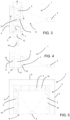
- the conveyor 3 comprises a plurality of supports which are movable along the motion trajectory; a unit for rotating the object 2 while on the support is associated with each support.
- the conveyor 3 may comprise at least two motive chains or belts 8, arranged side by side and parallel to one another, which run along the motion trajectory and hold up the supports.
- Each support comprises a pair of biconical rollers 9 mounted near to each other between the two motive chains or belts 8, and arranged so that their respective axes are perpendicular to the motion trajectory, in such a way that each object 2 can remain in the "cradle" defined by the two side-by-side biconical rollers 9.
- the unit for rotating the object 2 is advantageously arranged or shaped in such a way as to cause the rotation of at least one of the biconical rollers 9.
- this can be a fixed stop 10, such as a rail or track, on which a projecting end 11 of one of the biconical rollers 9 of each support rolls.
- the conveyor 3 may comprise a track equipped with rotating roller or rotating ball, wherein the rotating rollers or the rotating balls are arranged and/or actuated, at least in groups, in a different manner, thus causing the object 2 to rotate on itself as it is advanced.
- the conveyor 3 may comprise both a longitudinal advancement system (such as a conveyor belt 12) supporting (preferably from below) the objects 2 and causing longitudinal advancement thereof, and one or more fixed stops arranged along the motion trajectory to intercept the object 2 as it advances, and to cause it to rotate on itself (the object 2 being caused to rotate by impacting against the stops).
- a longitudinal advancement system such as a conveyor belt 12
- one or more fixed stops arranged along the motion trajectory to intercept the object 2 as it advances, and to cause it to rotate on itself (the object 2 being caused to rotate by impacting against the stops).
- the conveyor 3 comprises at least one movable element, mounted laterally to the motion trajectory and capable of coming into contact with the objects to make them rotate on themselves.
- the mobile element may be a belt which, where the object 2 is located, moves in an opposite direction to the advancement direction of the object 2; the contact of the belt against the surface of the object 2 while advancing causes the object 2 to rotate (the same result, albeit with a lower rotation speed, can also be obtained using a stationary belt).
- two movable elements are present, arranged at both sides of the lower conveyor belt 12 and running, respectively, in an opposite direction to the belt, and in the same direction as the belt but at a greater speed (advantageously, the absolute value of the speed difference of the two belts 13 relative to the conveyor belt 12 is the same).
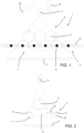
- the conveyor 3 comprises a plurality of distinct successive sections 14 (formed, for instance, by conveyor belts or similar devices), each of which defines a different advancement direction.
- each section 14 may develop perpendicularly to the previous section. The objects 2 pass from one section 14 to another in an uncontrolled manner, for instance simply by being pushed from the previous section 14 to the next section 14.
- these sections surround a central divergent-beam emitter 4 by at least 180°.
- the effect of each object 2 simply translating in a straight line along one of the sections is comparable to that which can be obtained on a shorter course by making it rotate on itself.
- the present invention offers significant advantages.
Landscapes
- Engineering & Computer Science (AREA)
- General Physics & Mathematics (AREA)
- Physics & Mathematics (AREA)
- Health & Medical Sciences (AREA)
- Theoretical Computer Science (AREA)
- Chemical & Material Sciences (AREA)
- Life Sciences & Earth Sciences (AREA)
- Immunology (AREA)
- Pathology (AREA)
- Analytical Chemistry (AREA)
- Biochemistry (AREA)
- General Health & Medical Sciences (AREA)
- Computer Vision & Pattern Recognition (AREA)
- Food Science & Technology (AREA)
- Nuclear Medicine, Radiotherapy & Molecular Imaging (AREA)
- Toxicology (AREA)
- Pulmonology (AREA)
- Radiology & Medical Imaging (AREA)
- Quality & Reliability (AREA)
- Multimedia (AREA)
- Medicinal Chemistry (AREA)
- Algebra (AREA)
- Mathematical Analysis (AREA)
- Mathematical Optimization (AREA)
- Mathematical Physics (AREA)
- Pure & Applied Mathematics (AREA)
- Analysing Materials By The Use Of Radiation (AREA)
- Apparatus For Radiation Diagnosis (AREA)
- Heterocyclic Carbon Compounds Containing A Hetero Ring Having Nitrogen And Oxygen As The Only Ring Hetero Atoms (AREA)
Applications Claiming Priority (2)
| Application Number | Priority Date | Filing Date | Title |
|---|---|---|---|
| IT102019000019454A IT201900019454A1 (it) | 2019-10-21 | 2019-10-21 | Metodo e apparecchiatura per l'esecuzione di un esame tomografico di un oggetto |
| EP20201080.7A EP3813022B1 (de) | 2019-10-21 | 2020-10-09 | Verfahren und vorrichtung zur durchführung einer tomografischen untersuchung eines objekts |
Related Parent Applications (2)
| Application Number | Title | Priority Date | Filing Date |
|---|---|---|---|
| EP20201080.7A Division-Into EP3813022B1 (de) | 2019-10-21 | 2020-10-09 | Verfahren und vorrichtung zur durchführung einer tomografischen untersuchung eines objekts |
| EP20201080.7A Division EP3813022B1 (de) | 2019-10-21 | 2020-10-09 | Verfahren und vorrichtung zur durchführung einer tomografischen untersuchung eines objekts |
Publications (2)
| Publication Number | Publication Date |
|---|---|
| EP4495886A2 true EP4495886A2 (de) | 2025-01-22 |
| EP4495886A3 EP4495886A3 (de) | 2025-04-23 |
Family
ID=69570778
Family Applications (2)
| Application Number | Title | Priority Date | Filing Date |
|---|---|---|---|
| EP20201080.7A Active EP3813022B1 (de) | 2019-10-21 | 2020-10-09 | Verfahren und vorrichtung zur durchführung einer tomografischen untersuchung eines objekts |
| EP24215718.8A Pending EP4495886A3 (de) | 2019-10-21 | 2020-10-09 | Verfahren und vorrichtung zur tomographischen untersuchung eines objektes |
Family Applications Before (1)
| Application Number | Title | Priority Date | Filing Date |
|---|---|---|---|
| EP20201080.7A Active EP3813022B1 (de) | 2019-10-21 | 2020-10-09 | Verfahren und vorrichtung zur durchführung einer tomografischen untersuchung eines objekts |
Country Status (6)
| Country | Link |
|---|---|
| US (1) | US11428648B2 (de) |
| EP (2) | EP3813022B1 (de) |
| AU (1) | AU2020256438B2 (de) |
| IL (1) | IL277972B2 (de) |
| IT (1) | IT201900019454A1 (de) |
| ZA (1) | ZA202006397B (de) |
Families Citing this family (8)
| Publication number | Priority date | Publication date | Assignee | Title |
|---|---|---|---|---|
| US10872688B2 (en) * | 2018-07-30 | 2020-12-22 | Arxium, Inc. | Visual analysis pill dispenser |
| IT202000014239A1 (it) | 2020-06-15 | 2021-12-15 | Biometic S R L | Tomografo computerizzato a tunnel e metodo per l’esecuzione di una tomografia computerizzata di un oggetto |
| CN113759431B (zh) * | 2021-06-09 | 2023-08-11 | 同方威视技术股份有限公司 | 安检数据关联方法和装置、以及x射线安检系统 |
| CN115598155B (zh) * | 2021-07-07 | 2025-02-18 | 清华大学 | 用于射线扫描设备的探测器的安装固定结构以及射线扫描设备 |
| IT202100021089A1 (it) * | 2021-08-04 | 2023-02-04 | Microtec Srl | Apparecchiatura sfogliatrice per tronchi |
| IT202100031448A1 (it) | 2021-12-15 | 2023-06-15 | Biometic S R L | Metodo e impianto per esaminare una carcassa animale |
| TWI872660B (zh) * | 2023-08-23 | 2025-02-11 | 台灣海博特股份有限公司 | 智能果實3d量測儀 |
| US20250297971A1 (en) * | 2024-03-19 | 2025-09-25 | Lumafield, Inc. | Limited angle x-ray system |
Citations (14)
| Publication number | Priority date | Publication date | Assignee | Title |
|---|---|---|---|---|
| US4989225A (en) | 1988-08-18 | 1991-01-29 | Bio-Imaging Research, Inc. | Cat scanner with simultaneous translation and rotation of objects |
| EP1283417A2 (de) | 2001-08-11 | 2003-02-12 | Heimann Systems GmbH | Verfahren und Anlage zur Inspektion eines Objektes, insbesondere eines Gepäckstückes |
| US6792066B1 (en) | 2002-05-15 | 2004-09-14 | Siemens Aktiengesellschaft | Method and control device for controlling a tomogram acquisition device |
| WO2005001775A1 (fr) | 2003-06-27 | 2005-01-06 | Commissariat A L'energie Atomique | Procede de reconstruction d'une image tomographique par une methode analytique comprenant une modelisation amelioree du mouvement de l'objet |
| CN2874482Y (zh) | 2005-12-09 | 2007-02-28 | 江西农业大学 | 水果高光谱图像采集装置 |
| WO2007136745A2 (en) | 2006-05-19 | 2007-11-29 | University Of Hawaii | Motion tracking system for real time adaptive imaging and spectroscopy |
| WO2008104627A1 (es) | 2007-02-27 | 2008-09-04 | Roda Iberica, S.L.U. | Sistema para la separación selectiva automática de cítricos afectados por podredumbre |
| FR2913850A1 (fr) | 2007-03-15 | 2008-09-19 | Cybernetix Sa Sa | Procede de tomographie |
| EP1983335A2 (de) | 2007-03-22 | 2008-10-22 | Tsinghua University | CT-Scan-Sicherheitsprüfgerät und -verfahren |
| WO2011042750A1 (en) | 2009-10-09 | 2011-04-14 | Ucl Business Plc | Tomosynthesis apparatus and method |
| US8031833B2 (en) | 2009-07-29 | 2011-10-04 | National Taiwan University | Portable inspection apparatus for X-ray tomography |
| IT1398460B1 (it) | 2009-06-09 | 2013-02-22 | Microtec Srl | Metodo per la classificazione di prodotti alimentari in grado di rotolare sulla propria superficie esterna, quali frutta ed ortaggi. |
| DE102012019851A1 (de) | 2012-10-10 | 2014-04-10 | Seidenader Maschinenbau Gmbh | Inspektionssystem zum Erstellen von wenigstens zwei Aufnahmen eines Guts |
| EP3106863A1 (de) | 2015-06-19 | 2016-12-21 | Universiteit Gent | Tomografie zur in-line-produktprüfung |
Family Cites Families (5)
| Publication number | Priority date | Publication date | Assignee | Title |
|---|---|---|---|---|
| JPS6364858A (ja) | 1986-09-04 | 1988-03-23 | Sumitomo Electric Ind Ltd | 車両のブレ−キ圧力制御装置 |
| ES2640955T3 (es) * | 2010-03-09 | 2017-11-07 | Perceptimed, Inc. | Verificación y dispensación de medicación |
| US10585206B2 (en) * | 2017-09-06 | 2020-03-10 | Rapiscan Systems, Inc. | Method and system for a multi-view scanner |
| CN108983306B (zh) * | 2018-06-06 | 2019-11-19 | 浙江大华技术股份有限公司 | 一种物品边框平滑显示的方法及安检设备 |
| JP7422689B2 (ja) * | 2018-06-29 | 2024-01-26 | デルタレイ・ベーフェー | 投影角度の動的選択による物品検査 |
-
2019
- 2019-10-21 IT IT102019000019454A patent/IT201900019454A1/it unknown
-
2020
- 2020-10-09 EP EP20201080.7A patent/EP3813022B1/de active Active
- 2020-10-09 EP EP24215718.8A patent/EP4495886A3/de active Pending
- 2020-10-12 IL IL277972A patent/IL277972B2/en unknown
- 2020-10-15 ZA ZA2020/06397A patent/ZA202006397B/en unknown
- 2020-10-16 US US17/072,982 patent/US11428648B2/en active Active
- 2020-10-16 AU AU2020256438A patent/AU2020256438B2/en active Active
Patent Citations (14)
| Publication number | Priority date | Publication date | Assignee | Title |
|---|---|---|---|---|
| US4989225A (en) | 1988-08-18 | 1991-01-29 | Bio-Imaging Research, Inc. | Cat scanner with simultaneous translation and rotation of objects |
| EP1283417A2 (de) | 2001-08-11 | 2003-02-12 | Heimann Systems GmbH | Verfahren und Anlage zur Inspektion eines Objektes, insbesondere eines Gepäckstückes |
| US6792066B1 (en) | 2002-05-15 | 2004-09-14 | Siemens Aktiengesellschaft | Method and control device for controlling a tomogram acquisition device |
| WO2005001775A1 (fr) | 2003-06-27 | 2005-01-06 | Commissariat A L'energie Atomique | Procede de reconstruction d'une image tomographique par une methode analytique comprenant une modelisation amelioree du mouvement de l'objet |
| CN2874482Y (zh) | 2005-12-09 | 2007-02-28 | 江西农业大学 | 水果高光谱图像采集装置 |
| WO2007136745A2 (en) | 2006-05-19 | 2007-11-29 | University Of Hawaii | Motion tracking system for real time adaptive imaging and spectroscopy |
| WO2008104627A1 (es) | 2007-02-27 | 2008-09-04 | Roda Iberica, S.L.U. | Sistema para la separación selectiva automática de cítricos afectados por podredumbre |
| FR2913850A1 (fr) | 2007-03-15 | 2008-09-19 | Cybernetix Sa Sa | Procede de tomographie |
| EP1983335A2 (de) | 2007-03-22 | 2008-10-22 | Tsinghua University | CT-Scan-Sicherheitsprüfgerät und -verfahren |
| IT1398460B1 (it) | 2009-06-09 | 2013-02-22 | Microtec Srl | Metodo per la classificazione di prodotti alimentari in grado di rotolare sulla propria superficie esterna, quali frutta ed ortaggi. |
| US8031833B2 (en) | 2009-07-29 | 2011-10-04 | National Taiwan University | Portable inspection apparatus for X-ray tomography |
| WO2011042750A1 (en) | 2009-10-09 | 2011-04-14 | Ucl Business Plc | Tomosynthesis apparatus and method |
| DE102012019851A1 (de) | 2012-10-10 | 2014-04-10 | Seidenader Maschinenbau Gmbh | Inspektionssystem zum Erstellen von wenigstens zwei Aufnahmen eines Guts |
| EP3106863A1 (de) | 2015-06-19 | 2016-12-21 | Universiteit Gent | Tomografie zur in-line-produktprüfung |
Non-Patent Citations (10)
| Title |
|---|
| BEISTER, MARCELDANIEL KOLDITZWILLI A. KALENDER: "Iterative reconstruction methods in X-ray CT.", PHYSICA MEDICA, vol. 28, no. 2, 2012, pages 94 - 108, XP028466903, DOI: 10.1016/j.ejmp.2012.01.003 |
| DE SCHRYVER, THOMAS ET AL.: "In-line NDT with X-Ray CT combining sample rotation and translation", NDT & E INTERNATIONAL, vol. 84, 2016, pages 89 - 98, XP029763394, DOI: 10.1016/j.ndteint.2016.09.001 |
| FELDKAMP, LEE A.L. C. DAVISJAMES W. KRESS, PRACTICAL CONE-BEAM ALGORITHM, 1984, pages 612 - 619 |
| GORIS, BART ET AL.: "Measuring lattice strain in three dimensions through electron microscopy", NANO LETTERS, vol. 15, no. 10, 2015, pages 6996 - 7001 |
| JANSSENS, ELINE ET AL.: "2015 IEEE International Conference on Image Processing (ICIP", 2015, IEEE, article "Neural network based X-ray tomography for fast inspection of apples on a conveyor belt system" |
| LUIS F ALVES PEREIRA ET AL.: "Inline discrete tomography system: Application to agricultural product inspection", COMPUTERS AND ELECTRONICS IN AGRICULTURE, vol. 138, pages 117 - 126, XP085024300, DOI: 10.1016/j.compag.2017.04.010 |
| PARKINSON, DILWORTH Y ET AL.: "Automatic alignment and reconstruction of images for soft X-ray tomography", JOURNAL OF STRUCTURAL BIOLOGY, vol. 177, no. 2, 2012, pages 259 - 266, XP028891903, DOI: 10.1016/j.jsb.2011.11.027 |
| PICCOLOMINI, ELENA LOLIFABIANA ZAMA: "The conjugate gradient regularization method in computed tomography problems", APPLIED MATHEMATICS AND COMPUTATION, vol. 102, no. 1, 1999, pages 87 - 99 |
| VAN DAEL, MATTIAS ET AL.: "Comparison of methods for online inspection of apple internal quality", ONLINE E-JOURNAL OF NONDESTRUCTIVE TESTING, 2017 |
| YANG, CHAOESMOND G. NGPAWEL A. PENCZEK: "Unified 3-D structure and projection orientation refinement using quasi-Newton algorithm", JOURNAL OF STRUCTURAL BIOLOGY, vol. 149, no. 1, 2005, pages 53 - 64, XP027514433, DOI: 10.1016/j.jsb.2004.08.010 |
Also Published As
| Publication number | Publication date |
|---|---|
| EP3813022B1 (de) | 2025-01-15 |
| US20210116395A1 (en) | 2021-04-22 |
| AU2020256438A1 (en) | 2021-05-06 |
| AU2020256438B2 (en) | 2025-06-19 |
| EP3813022C0 (de) | 2025-01-15 |
| US11428648B2 (en) | 2022-08-30 |
| IL277972B2 (en) | 2024-05-01 |
| IL277972B1 (en) | 2024-01-01 |
| IT201900019454A1 (it) | 2021-04-21 |
| EP4495886A3 (de) | 2025-04-23 |
| ZA202006397B (en) | 2023-10-25 |
| IL277972A (en) | 2021-04-29 |
| EP3813022A1 (de) | 2021-04-28 |
Similar Documents
| Publication | Publication Date | Title |
|---|---|---|
| EP3813022B1 (de) | Verfahren und vorrichtung zur durchführung einer tomografischen untersuchung eines objekts | |
| JP5350222B2 (ja) | 多視角荷物セキュリティ検査方法 | |
| Van Dael et al. | Combination of shape and X-ray inspection for apple internal quality control: In silico analysis of the methodology based on X-ray computed tomography | |
| US6813374B1 (en) | Method and apparatus for automatic image quality assessment | |
| JP5075911B2 (ja) | 荷物セキュリティ検査システム | |
| JP7641183B2 (ja) | 被験者のct検査を実行するctスキャナ及び方法 | |
| US8254519B2 (en) | X-ray inspection apparatus and X-ray inspection method | |
| CA2979932A1 (en) | Automated quality control and selection | |
| JP6487703B2 (ja) | X線検査装置及びx線検査方法 | |
| US20050078861A1 (en) | Tomographic system and method for iteratively processing two-dimensional image data for reconstructing three-dimensional image data | |
| US8670522B2 (en) | Stereo X-ray inspection apparatus and method for forming three-dimensional image through volume reconstruction of image acquired from the same | |
| EP3106863A1 (de) | Tomografie zur in-line-produktprüfung | |
| JP2010127810A (ja) | X線検査装置およびx線検査方法 | |
| CN114004765A (zh) | 一种安检设备中dr透视图像的畸变校正方法及装置 | |
| US9633428B2 (en) | Automatic occlusion region identification using radiation imaging modality | |
| CN102901740A (zh) | 一种通道式四视角x射线液态物品安全检查系统 | |
| JP3572191B2 (ja) | X線ctスキャナ装置 | |
| US20170059496A1 (en) | System and method for tire inspection | |
| JP7515875B2 (ja) | センターシフト量推定装置、方法およびプログラム | |
| US20250297971A1 (en) | Limited angle x-ray system | |
| Teramoto et al. | High speed oblique CT system for solder bump inspection | |
| Park et al. | Computed Laminography System with Various Scanning Configurations for Nondestructive Testing | |
| Herremans et al. | X-ray vision to detect ca induced disorders in'Braeburn'apples: from microstructure imaging to on-line sorting | |
| HK1115443A (en) | A security check system and method with multiple viewing angle for aviation containers |
Legal Events
| Date | Code | Title | Description |
|---|---|---|---|
| PUAI | Public reference made under article 153(3) epc to a published international application that has entered the european phase |
Free format text: ORIGINAL CODE: 0009012 |
|
| STAA | Information on the status of an ep patent application or granted ep patent |
Free format text: STATUS: THE APPLICATION HAS BEEN PUBLISHED |
|
| AC | Divisional application: reference to earlier application |
Ref document number: 3813022 Country of ref document: EP Kind code of ref document: P |
|
| AK | Designated contracting states |
Kind code of ref document: A2 Designated state(s): AL AT BE BG CH CY CZ DE DK EE ES FI FR GB GR HR HU IE IS IT LI LT LU LV MC MK MT NL NO PL PT RO RS SE SI SK SM TR |
|
| PUAL | Search report despatched |
Free format text: ORIGINAL CODE: 0009013 |
|
| AK | Designated contracting states |
Kind code of ref document: A3 Designated state(s): AL AT BE BG CH CY CZ DE DK EE ES FI FR GB GR HR HU IE IS IT LI LT LU LV MC MK MT NL NO PL PT RO RS SE SI SK SM TR |
|
| RIC1 | Information provided on ipc code assigned before grant |
Ipc: G06T 11/00 20060101AFI20250317BHEP |
|
| STAA | Information on the status of an ep patent application or granted ep patent |
Free format text: STATUS: REQUEST FOR EXAMINATION WAS MADE |
|
| 17P | Request for examination filed |
Effective date: 20250627 |