EP1983335A2 - CT-Scan-Sicherheitsprüfgerät und -verfahren - Google Patents
CT-Scan-Sicherheitsprüfgerät und -verfahren Download PDFInfo
- Publication number
- EP1983335A2 EP1983335A2 EP08005062A EP08005062A EP1983335A2 EP 1983335 A2 EP1983335 A2 EP 1983335A2 EP 08005062 A EP08005062 A EP 08005062A EP 08005062 A EP08005062 A EP 08005062A EP 1983335 A2 EP1983335 A2 EP 1983335A2
- Authority
- EP
- European Patent Office
- Prior art keywords
- conveying
- security check
- checked article
- scan
- check device
- Prior art date
- Legal status (The legal status is an assumption and is not a legal conclusion. Google has not performed a legal analysis and makes no representation as to the accuracy of the status listed.)
- Withdrawn
Links
Images

Classifications
-
- G—PHYSICS
- G01—MEASURING; TESTING
- G01V—GEOPHYSICS; GRAVITATIONAL MEASUREMENTS; DETECTING MASSES OR OBJECTS; TAGS
- G01V5/00—Prospecting or detecting by the use of ionising radiation, e.g. of natural or induced radioactivity
- G01V5/20—Detecting prohibited goods, e.g. weapons, explosives, hazardous substances, contraband or smuggled objects
- G01V5/22—Active interrogation, i.e. by irradiating objects or goods using external radiation sources, e.g. using gamma rays or cosmic rays
- G01V5/226—Active interrogation, i.e. by irradiating objects or goods using external radiation sources, e.g. using gamma rays or cosmic rays using tomography
Definitions
- the present invention relates to the radiation detection field, and more particularly to a CT scan security check device and method for performing a security check on baggage articles.
- the radiation-ray-type security check technique for baggage articles is mainly divided into an x-ray two dimension imaging technique and a CT imaging technique.
- the requirement of baggage articles security check is increased, based on the prominent technical advantages of the CT imaging technique per se over the x-ray two dimension imaging technique, the importance of the CT imaging technique in baggage articles security check work is more apparent.
- the existing baggage articles CT imaging technique borrows ideas from medical CT technical solutions, that is, the baggage articles security check is carried out by a cooperation of a continuous rotation movement of the radiation source and the detector about a horizontal axis and a horizontal movement of the baggage articles.
- the medical CT imaging technique has been developed for a longer time and some mature experiences may be referred to for main relative members (such as slip ring, etc.), which provides a reliable technical guarantee for the development of baggage articles CT scan devices.
- the main relative members are required both to meet the reliability of continuous rotation and to implement the information communication of high speed and large amount data as well as the electric power support, so that the technical difficulty is large and the design and production cost is very high, thus disadvantageous to the spreading and application of the baggage articles CT imaging technique.
- the present invention provides a CT scan security check device, comprising a radiation source and a detector which form a radiation detection area, and a conveyer mechanism which conveys a checked article along a conveying path, and also comprising a multidimensional movement mechanism which makes the checked article and the radiation detection area generate a relative displacement in a vertical direction and makes the checked article rotate about a vertical axis.
- the multidimensional movement mechanism comprises : a rotation mechanism disposed in the conveying path and operatively making the checked article rotate after the checked article is conveyed to the rotation mechanism by the conveyer mechanism; and a vertically lifting and lowering mechanism which makes the checked article conveyed to the rotation mechanism generate a relative movement in the vertical direction to the radiation detection area.
- the radiation source and the detector are mounted to the vertically lifting and lowering mechanism.
- the rotation mechanism is rotatably mounted on the vertically lifting and lowering mechanism.
- the radiation source and the detector are mounted to a radiation protection shield of the CT scan security check device; or alternatively, the CT scan security check device further comprises a secondary vertically lifting and lowering mechanism, and the radiation source and the detector are mounted to the secondary vertically lifting and lowering mechanism.
- the vertically lifting and lowering mechanism comprises a load-bearing platform and a vertically lifting and lowering electromotor to drive the load-bearing platform to move in the vertical direction.
- the rotation mechanism comprises: a support plate rotatably mounted on the load-bearing platform; a plurality of support rollers mounted on the support plate which rotate together with the support plate and bring the checked article to rotate after the checked article is conveyed on the plurality of support rollers by the conveyer mechanism; and a rotation electromotor mounted within an internal cavity of the load-bearing platform and operatively driving the support plate to rotate about the vertical axis.
- the plurality of support rollers are configured to be locked when the checked article is wholly conveyed thereonto, and to rotate to convey the checked article in a horizontal direction out from the rotation mechanism after the CT scan of the checked article is completed.
- At least one sensor to detect whether or not the checked article is wholly conveyed onto the plurality of support rollers.
- the conveyer mechanism comprises a conveying-in mechanism and a conveying-out mechanism located respectively on both sides of the multidimensional movement mechanism in the conveying path.
- a conveying-out port of the conveying-in mechanism is at a height identical to a conveying-in port of the conveying-out mechanism; and the conveying-in mechanism and the conveying-out mechanism are preferably conveyer belt mechanisms of which the conveying directions are configured to be horizontal.
- the present invention provides a CT scan security check method, comprising the following steps: 1) making the checked article and the radiation detection area generate a relative displacement in a vertical direction and making the checked article to perform a rotation movement; 2) during the checked article passing through the radiation detection area, obtaining information data on the radiation ray through the checked article; and 3) transmitting out the information data for CT arithmetic reconstruction.
- step 1) the checked article performs a vertical lifting and lowering movement and a rotation movement, and the radiation detection area is stationary; or alternatively the checked article performs a rotation movement, and the radiation detection area performs a vertical movement; or alternatively the checked article performs a vertical lifting and lowering movement and a rotation movement, and the radiation detection area performs another vertical lifting and lowering movement.
- the CT scan security check method comprises the following steps: conveying the checked article to a check position prior to step 1); and/or conveying the checked article away from the check position after step 3).
- the present invention due to adopting the technical solution of making the checked article and the radiation detection area generate a relative displacement in a vertical direction and making the checked article perform a rotation movement, it can be achieved to perform a CT-scan-security-check on the checked article without the rotation of the radiation source and the detector, reducing the technical difficulty and design and production cost of CT-scan-security-check.
- the present invention further provides a automatic conveyer mechanism and necessary sensors so that the checked article can be checked automatically and continuously, and provides a secondary vertically lifting and lowering mechanism for the radiation source and the detector, speeding up the procedure of CT scan security check.
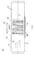
- Figure 1 is a horizontal sectional view of a CT scan security check device in accordance with the first embodiment of the present invention wherein an upper portion of the radiation protection shield is cut away to show the internal structure of the CT scan security check device;
- Figure 2 is a longitudinal sectional view of the CT scan security check device of Figure 1 ;
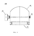
- Figure 3 is a left view of the CT scan security check device of Figure 1 (a vertically lifting and lowering mechanism seeable below the conveyer mechanism is omitted in Figure 3 );
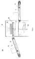
- Figure 4 is a structural schematic view of a CT scan security check device in accordance with the second embodiment of the present invention.
- a CT scan security check device 100 in accordance with the first embodiment of the present invention comprises generally a radiation source 20 and a detector 30 which form a radiation detection area, and a conveyer mechanism 10 which conveys a checked article 70 along a conveying path A .
- the radiation detection area is schematically shown by two dash dot lines in Figure 1 .
- the radiation source 20 may be generally one or more x-ray sources or isotope sources of which the energy is configured to be adjustable.
- the detector 30 may be a one-dimensional detector array or two-dimensional detector array, and these detector arrays may be single-layer structure or multi-layer structure.
- the shape of the radiation detection area depends on the form or type of the adopted detector. If the detector adopts a rectangular two-dimensional detector array, the radiation beam should be reshaped into a rectangle by means of a collimator; and if the detector adopts a one-dimensional linear detector, the radiation beam should be reshaped into a linear shape by means of a collimator.
- the CT scan security check device 100 also comprises a multidimensional movement mechanism 80 which makes the checked article 70 and the radiation detection area generate a relative displacement in a vertical direction and makes the checked article 70 rotate about a vertical axis.
- a multidimensional movement mechanism 80 which makes the checked article 70 and the radiation detection area generate a relative displacement in a vertical direction and makes the checked article 70 rotate about a vertical axis.
- the position of the multidimensional movement mechanism 80 in the conveying path A is herein referred to as "check position". It will be appreciated for those skilled in the art that the check position is in the conveying path A in the radiation detection area, and is under or over the radiation detection area.
- the multidimensional movement mechanism 80 comprises a rotation mechanism 50 and a vertically lifting and lowering mechanism 60.
- the rotation mechanism 50 is disposed in the conveying path A of the conveyer mechanism 10, and after the checked article 70 is conveyed to the rotation mechanism 50 by the conveyer mechanism 10, the rotation mechanism 50 operatively makes the checked article 70 rotate and the vertically lifting and lowering mechanism 60 makes the checked article 70 conveyed to the rotation mechanism 50 generate a relative movement in the vertical direction to the radiation detection area.
- such a description or definition of a feature or mechanism being “in the conveying path” or “on the conveying path” includes locating the feature or mechanism in or on extended line(s) of the conveying path or connecting line(s) between several segments of the conveying path (since the extended line(s) of the conveying path or the connecting line(s) between several segments of the conveying path may be generally viewed as part of the conveying path), as easily understood by those skilled in the art.
- the conveying path A may be divided into two segments, the first segment being a conveying-in path by which the conveyer mechanism 10 conveys the checked article 70 onto the rotation mechanism 50 and the second segment being a conveying-out path by which the conveyer mechanism 10 receives the CT scanned checked article 70 from the rotation mechanism 50 and conveys it out.
- the rotation mechanism 50 may be deposed in a connecting line between the conveying-in path and the conveying-out path.
- the conveying-in path and the conveying-out path are generally in line.
- the rotation mechanism 50 is rotatably mounted on the vertically lifting and lowering mechanism 60.
- the radiation source 20 and the detector 30 may be connected with each other by rigid member(s), and for example, they may be mounted to the radiation protection shield 40 of the CT scan security check device 100.
- the radiation source 20 is mounted on one side of the radiation protection shield 40, and the detector 30 is mounted on the other side of the radiation protection shield 40 opposite to the radiation source 20.
- the sectional shape of the radiation protection shield 40 may be generally configured into an approximately inverse U-shape or any other suitable shapes, such as a half-circle shape.
- the vertically lifting and lowering mechanism 60 comprises a load-bearing platform 61 and a vertically lifting and lowering electromotor 65 driving the load-bearing platform 61 to move in the vertical direction.
- driving or “drive” used herein includes the meanings of "directly driving” or “indirectly driving via other transmission mechanisms”.
- between the vertically lifting and lowering electromotor 65 and the load-bearing platform 61 is preferably provided a threaded spindle and nut mechanism, and the load-bearing platform 61 is fixed on the top of the threaded spindle 62.
- the vertically lifting and lowering electromotor 65 directly or indirectly drives a nut (not shown in the drawings), which then makes the threaded spindle 62 fitting with the nut to move in the vertical direction to bring the load-bearing platform 61 to move in the vertical direction.
- the rotation mechanism 50 comprises a support plate 52, a plurality of support rollers 53 and a rotation electromotor 55.
- the support plate 52 is rotatably mounted on the load-bearing platform 61 of the vertically lifting and lowering mechanism 60 and can move in the vertical direction along with the load-bearing platform 61.
- the rotation electromotor 55 is mounted in an internal cavity of the load-bearing platform 61, operatively driving the support plate 52 to rotate about the vertical axis.
- the rotation electromotor 55 is mounted at the upper portion of the internal cavity of the load-bearing platform 61.
- the support rollers 53 are mounted on the support plate 52. After the checked article 70 is wholly conveyed onto the support rollers 53, the support rollers 53 are locked and no longer rotate about its pivot axis. Of course, the support rollers 53 can rotate together with the support plate 52 about the vertical axis and carry the checked article 70 to rotate.
- the support rollers 53 are configured to actively rotate after the CT scan on the checked article 70 is completed, in order to convey the checked article 70 out in the horizontal direction away from the rotation mechanism 50.
- the support plate 52 is configured that: before the support plate 52 begins to be rotated, its angle position is oriented such that the pivot axis of the support rollers 53 is perpendicular to the conveying-in path; and after this CT scan is completed, the angle position is oriented such that the pivot axes of the plurality of support rollers 53 are perpendicular to the conveying-out path when the support plate 52 stops to rotate.
- any suitable means may be adopted to detect whether or not the checked article 70 is wholly conveyed onto the support rollers 53.
- this detection may be achieved by providing at least one sensor 54 on the support plate 52. Once a certain signal arises in the at least one sensor 54, a control system of the CT scan security check device can control the support rollers 53 to stop rotating and be locked in order to ensure the checked article to be stationary relative to the support rollers 53; and after the CT scan is completed, the control system sends a rotation signal to the support rollers 53, and the support rollers 53 are rotated to convey out the checked article 70 along the horizontal direction.
- the sensors 54 are preferably weight sensors which can automatically sense whether the checked article is already conveyed onto the rotation mechanism 50 (i.e., whether the checked article is conveyed onto the support rollers 53).
- two weight sensors may be provided respectively at suitable positions on the support plate 52 near to the conveying-in mechanism 12, and another two weight sensors may be provided respectively at suitable positions on the support plate 52 near to the conveying-out mechanism 14. In this way, by means of a series of logic relations easily configured, it can be detected whether or not the checked article 70 is wholly conveyed onto the support rollers 53, and preferably whether or not the checked article 70 is conveyed in the centre of the rotation mechanism 50.
- the distance between the two groups of sensors is L (the length of the checked article 70 is less than the distance L)
- the time period from after no signal arises in the first group of sensors to before the support rollers 53 stops to rotate and be locked can be calculated, such that the checked article 70 is just conveyed in the center of the support plate 52.
- the signaling interval of the second group of sensors it can be detected whether or not the checked article 70 wholly departs away from the support rollers 53 or the rotation mechanism 50. It should be appreciated by those skilled in the art that it is possible to adopt position sensors to perform such detection.
- the conveyer mechanism 10 may comprise a conveying-in mechanism 10 and a conveying-out mechanism 14 which are respectively located on both sides of the multidimensional movement mechanism 80 in the conveying path A.
- the conveying-out port of the conveying-in mechanism 12 extends into the radiation protection shield 40 so as to convey the checked article 70 into the radiation protection shield 40 and further convey it onto the support rollers 53 of the support plate 52.
- the conveying-in port of the conveying-out mechanism 14 is also located in the radiation protection shield 40 so as to receive the checked article 70 conveyed from the support rollers 53 of the support plate 52, and to convey the checked article 70 away from the radiation protection shield 40 after the check is completed.
- the conveying-out port of the conveying-in mechanism 12 is at a height identical to the conveying-in port of the conveying-out mechanism 14, and the conveying-in mechanism 12 and the conveying-out mechanism 14 are preferably conveyer belt mechanisms of which the conveying directions are configured to be horizontal.
- the radiation source 20 and the detector 30 are generally first set to the operating state to form the radiation detection area; then the checked article 70 is placed on the conveying-in mechanism 12 at the input port and conveyed onto the rotation mechanism 50 by the conveying-in mechanism 12. Once the checked article 70 is conveyed onto the support rollers 53 on the support plate 52, the sensor 54 can automatically sense it, and then the support rollers 53 are locked to make the checked article 70 stationary on the support rollers 53 and the rotation mechanism 50 bring the checked article 70 to rotate together.
- the vertically lifting and lowering electromotor 65 of the vertically lifting and lowering mechanism 60 drives the nut to rotate, and the nut in turn drives the threaded spindle 62 and further drives the load-bearing platform 61 which carries the rotation mechanism 50 to performs the vertical lifting and lowering movement so as to complete the CT scan process.
- the rotation mechanism 50 and the lifting and lowering mechanism 60 come back to their initial states, then the support rollers 53 on the rotation mechanism 50 automatically rotate to convey the checked article 70 onto the conveying-out mechanism 14, and then the conveying-out mechanism 14 conveys the checked article away from the CT scan security check device 100.
- the above-mentioned action processes can be controlled and completed by means of existing circuits.
- the structure of the CT scan security check device 200 in accordance with the second embodiment of the present invention is substantially identical to that of the first embodiment of the present invention. But in the CT scan security check device 200, there is a height difference between the conveying-out port of the conveying-in mechanism 12 and the conveying-in port of the conveying-out mechanism 14.
- the height difference is configured to at least equal to a vertical travel distance of the vertically lifting and lowering mechanism 60 in a check process.
- at least one of the conveying-in mechanism 12 and the conveying-out mechanism 14 is a conveyer belt mechanism of which the conveying direction is configured to be inclined.
- the conveying-in mechanism 12 is a conveyer belt mechanism of which the conveying direction is configured to be inclined upwards
- the conveying-out mechanism 14 is a conveyer belt mechanism of which the conveying direction is configured to be horizontal, wherein the position of the conveying-out port of the conveying-in mechanism 12 is above that of the conveying-in port.
- a secondary vertically lifting and lowering mechanism (not shown in the drawings) may be provided for the radiation source 20 and the detector 30.
- the checked article performs a vertical lifting and lowering movement along with the vertically lifting and lowering mechanism 60
- the radiation source 20 and the detector 30 perform another vertical lifting and lowering movement along with the secondary vertically lifting and lowering mechanism, which not only is advantageous to expedite the scan speed, but also is particularly advantageous in some applications where the checked article is inconvenient to perform a larger travel distance of vertical lifting and lowering movement.
- the checked article performs separately a lifting and lowering movement and a rotation movement by the action of the vertically lifting and lowering mechanism and the rotation mechanism, so as to pass through the radiation detection area and complete the CT scan.
- the radiation source 20 and the detector 30, rather than the rotation mechanism 50 may be mounted to the vertically lifting and lowering mechanism 60.
- the conveyer mechanism 10, the rotation mechanism 50 and the vertically lifting and lowering mechanism 60 of the present invention are independent to each other (in other words, these mechanism may perform their respective movements independently to each other).
- the checked article 70 is conveyed onto the rotation mechanism 50 by the conveyer mechanism 10, cooperating with the vertical lifting and lowering movement of the radiation source 20 and the detector 30 driven by the vertically lifting and lowering mechanism 60 so that the radiation detection area passes through the rotating checked article to realize the CT scan of the article.
- Such an alternative embodiment is particularly advantageous in some applications where the checked article is inconvenient to perform a larger travel distance of vertical lifting and lowering movement.
- the present invention provides a CT scan security check method.
- the devices to perform the check method comprise but are not limited to the CT scan security check devices provided by the present invention.
- the checked article may be firstly conveyed to the check position. Then, the checked article and the radiation detection area are made to generate a relative displacement in a vertical direction, and the checked article per se is made to perform independently a rotation movement.
- the checked article performs a vertical lifting and lowering movement and a rotation movement, and the radiation detection area is stationary; or the checked article performs a rotation movement, and the radiation detection area performs a vertical movement; or the checked article performs a vertical lifting and lowering movement and a rotation movement, and the radiation detection area performs another vertical lifting and lowering movement.
- the information data on the radiation ray through the checked article is obtained and then transmitted out for CT arithmetic reconstruction. Then, the checked article may be conveyed away from the check position as desired.
- Such steps are well-known or easily achieved for those skilled in the art and are not described in detail herein for purposes of simplicity.
- the inventive concepts may be applied to some radiation ray scan security-check device or method which synthetically adopts an x-ray two-dimensional imaging technique and a CT imaging technique.
- the transmission mechanisms such as gear-rack mechanism, cam-lifter mechanism, crank-slider mechanism and the like may be adopted or some linear motor may be directly adopted so as to alternatively achieve the vertically lifting and lowering mechanism. Therefore, the protection scope of the present invention is intended to be defined by the claims appended hereto and their equivalents, and all modifications, alternatives and equivalents of the exemplary embodiments should be included in the scope of the present invention.
Landscapes
- Physics & Mathematics (AREA)
- High Energy & Nuclear Physics (AREA)
- Life Sciences & Earth Sciences (AREA)
- General Life Sciences & Earth Sciences (AREA)
- General Physics & Mathematics (AREA)
- Geophysics (AREA)
- Analysing Materials By The Use Of Radiation (AREA)
Applications Claiming Priority (1)
| Application Number | Priority Date | Filing Date | Title |
|---|---|---|---|
| CNA2007100646625A CN101271075A (zh) | 2007-03-22 | 2007-03-22 | 一种ct扫描安全检查方法及其装置 |
Publications (2)
| Publication Number | Publication Date |
|---|---|
| EP1983335A2 true EP1983335A2 (de) | 2008-10-22 |
| EP1983335A3 EP1983335A3 (de) | 2010-09-15 |
Family
ID=39737583
Family Applications (1)
| Application Number | Title | Priority Date | Filing Date |
|---|---|---|---|
| EP08005062A Withdrawn EP1983335A3 (de) | 2007-03-22 | 2008-03-18 | CT-Scan-Sicherheitsprüfgerät und -verfahren |
Country Status (4)
| Country | Link |
|---|---|
| US (1) | US20080232541A1 (de) |
| EP (1) | EP1983335A3 (de) |
| CN (1) | CN101271075A (de) |
| RU (1) | RU2383882C2 (de) |
Cited By (1)
| Publication number | Priority date | Publication date | Assignee | Title |
|---|---|---|---|---|
| IT201900019454A1 (it) | 2019-10-21 | 2021-04-21 | Microtec Srl | Metodo e apparecchiatura per l'esecuzione di un esame tomografico di un oggetto |
Families Citing this family (39)
| Publication number | Priority date | Publication date | Assignee | Title |
|---|---|---|---|---|
| RU2431825C1 (ru) * | 2010-05-28 | 2011-10-20 | Открытое акционерное общество "Федеральный научно-производственный центр "Алтай" | Промышленный томограф |
| CN102455443A (zh) * | 2010-10-21 | 2012-05-16 | 上海世鹏实验室科技发展有限公司 | 一种人体或物品安全探测扫描装置 |
| CN102621166A (zh) * | 2011-01-30 | 2012-08-01 | 中铁快运股份有限公司 | 自行式辐射物品检查系统及其检查方法 |
| CN102359971A (zh) * | 2011-09-14 | 2012-02-22 | 上海英迈吉东影图像设备有限公司 | 一种实现单源多视角安全检查的方法及系统 |
| CN104215648B (zh) * | 2013-06-05 | 2016-09-07 | 中国石油天然气股份有限公司 | X射线检测射源自动定位装置 |
| CN103330574A (zh) * | 2013-07-10 | 2013-10-02 | 沈阳东软医疗系统有限公司 | 一种扫描床 |
| CN105094725B (zh) * | 2014-05-14 | 2019-02-19 | 同方威视技术股份有限公司 | 图像显示方法 |
| WO2016141595A1 (zh) * | 2015-03-12 | 2016-09-15 | 罗艺 | 一种x光检测设备 |
| CN104914475A (zh) * | 2015-06-30 | 2015-09-16 | 江西理工大学 | 一种金属探测装置 |
| CN106290418A (zh) * | 2016-08-31 | 2017-01-04 | 天津三英精密仪器股份有限公司 | 一种适合长样品的ct检测仪 |
| US10845499B2 (en) | 2017-01-21 | 2020-11-24 | Idss Holdings, Inc. | Systems and methods for scanning palletized cargo |
| US10724973B2 (en) | 2017-01-21 | 2020-07-28 | Idss Holdings, Inc. | Systems and methods for scanning palletized cargo |
| CN108375591B (zh) * | 2018-05-07 | 2024-11-12 | 丹东锐新射线仪器有限公司 | 一种探伤射线发射装置、探伤射线接收装置和探伤装置 |
| US10724972B2 (en) * | 2018-05-23 | 2020-07-28 | Saudi Arabian Oil Company | Method and apparatus for CT scanning of longer whole cores |
| WO2020018515A1 (en) * | 2018-07-20 | 2020-01-23 | Idss Holdings, Inc. | Systems and methods for scanning palletized cargo |
| CN109521484B (zh) * | 2019-01-04 | 2024-05-14 | 同方威视技术股份有限公司 | 扫描装置及其转场方法 |
| CN110844538B (zh) * | 2019-12-06 | 2024-05-24 | 深圳市拓野机器人自动化有限公司 | 一种带方向辨别及换向功能的盖板投入机构及使用方法 |
| CN111122628B (zh) * | 2019-12-26 | 2025-05-30 | 宁波市宇华电器有限公司 | 基于康普顿背散射的聚乙烯管件无损检测装置 |
| CN211741602U (zh) * | 2020-01-17 | 2020-10-23 | 德瑞科(天津)机械制造有限公司 | 一种安检机 |
| CN111301993B (zh) * | 2020-04-02 | 2024-02-13 | 宁夏巨能机器人股份有限公司 | 一种桁架机械手的上料道单元 |
| CN111731749B (zh) * | 2020-04-29 | 2025-04-08 | 宝武集团马钢轨交材料科技股份有限公司 | 一种用于火车车轮运输辊道中的升降装置及其使用方法 |
| CN111708071B (zh) * | 2020-06-05 | 2022-08-05 | 成都理工大学 | 核废物包装体流水线式扫描检测装置 |
| CN113830510B (zh) * | 2020-06-23 | 2023-05-23 | 同方威视技术股份有限公司 | 输送装置、以及检查系统 |
| CN112591377B (zh) * | 2020-12-18 | 2025-01-03 | 江苏丽阳电子仪表有限公司 | 一种用于智能电表测试的送表装置 |
| CN113296142B (zh) * | 2021-05-21 | 2023-01-17 | 山西中辐核仪器有限责任公司 | 传送带式安全帽污染监测仪 |
| CN115598715B (zh) * | 2021-07-07 | 2024-10-15 | 同方威视技术股份有限公司 | 检查系统和方法 |
| JP7743746B2 (ja) * | 2021-09-30 | 2025-09-25 | オムロン株式会社 | 検査装置 |
| CN113916917A (zh) * | 2021-10-20 | 2022-01-11 | 北京航星机器制造有限公司 | 一种基于ct技术的安检系统及其检测方法 |
| CN114185102A (zh) * | 2021-12-29 | 2022-03-15 | 同方威视技术股份有限公司 | 检查设备 |
| DE102022111511A1 (de) * | 2022-05-09 | 2023-11-09 | Wipotec Gmbh | Inspektionsvorrichtung mit darin integrierter Röntgen- und Wägevorrichtung |
| CN116812439B (zh) * | 2022-07-04 | 2024-05-31 | 同方威视技术股份有限公司 | 传送系统以及检测设备 |
| CN115656231B (zh) * | 2022-10-26 | 2025-07-22 | 天津三英精密仪器股份有限公司 | 一种船载全岩心ct扫描成像检测装置 |
| CN115753850B (zh) * | 2022-11-30 | 2024-06-28 | 清华大学 | 一种ct检测系统、方法及装置 |
| CN116818812B (zh) * | 2023-06-12 | 2024-05-14 | 同方威视技术股份有限公司 | 检测装置及用于电芯检测的检测方法 |
| CN117092143A (zh) * | 2023-10-11 | 2023-11-21 | 丹东华日理学电气有限公司 | 一种检测平面薄板类工件的ct射线数字成像设备 |
| CN119654552A (zh) * | 2023-10-23 | 2025-03-18 | 深圳市亚锐智能科技有限公司 | 电池工业ct检测线 |
| DE102023211879A1 (de) * | 2023-11-28 | 2025-05-28 | Smiths Detection Germany Gmbh | Erkennungsvorrichtung zum erkennen wenigstens eines gefahrobjekts in einem gepäckstück |
| CN117985384B (zh) * | 2024-03-23 | 2024-12-13 | 株洲市金丰米业有限公司 | 一种大米仓库进销存用信息录入方法 |
| CN119079458B (zh) * | 2024-11-11 | 2025-02-11 | 四川并济科技有限公司 | 一种pcb板双面检测的输送装置 |
Family Cites Families (11)
| Publication number | Priority date | Publication date | Assignee | Title |
|---|---|---|---|---|
| US4422177A (en) * | 1982-06-16 | 1983-12-20 | American Science And Engineering, Inc. | CT Slice proximity rotary table and elevator for examining large objects |
| US4989225A (en) * | 1988-08-18 | 1991-01-29 | Bio-Imaging Research, Inc. | Cat scanner with simultaneous translation and rotation of objects |
| SU1608526A1 (ru) * | 1989-01-13 | 1990-11-23 | Всесоюзный научно-исследовательский проектно-конструкторский и технологический институт кабельной промышленности | Рентгеновское вычислительное томографическое устройство |
| US5119408A (en) * | 1990-10-31 | 1992-06-02 | General Electric Company | Rotate/rotate method and apparatus for computed tomography x-ray inspection of large objects |
| US5712926A (en) * | 1994-10-20 | 1998-01-27 | Eberhard; Jeffrey Wayne | X-ray computed tomography (CT) system for detecting thin objects |
| DE10139672A1 (de) * | 2001-08-11 | 2003-03-06 | Heimann Systems Gmbh & Co | Verfahren und Anlage zur Inspektion eines Objektes, insbesondere eines Gepäckstückes |
| US7356115B2 (en) * | 2002-12-04 | 2008-04-08 | Varian Medical Systems Technology, Inc. | Radiation scanning units including a movable platform |
| US7672426B2 (en) * | 2002-12-04 | 2010-03-02 | Varian Medical Systems, Inc. | Radiation scanning units with reduced detector requirements |
| US7062011B1 (en) * | 2002-12-10 | 2006-06-13 | Analogic Corporation | Cargo container tomography scanning system |
| GB2452187B (en) * | 2004-11-26 | 2009-05-20 | Nuctech Co Ltd | Computed Tomography apparatus for detecting unsafe liquids |
| JP4730526B2 (ja) * | 2005-06-27 | 2011-07-20 | 独立行政法人理化学研究所 | 封入物検査装置 |
-
2007
- 2007-03-22 CN CNA2007100646625A patent/CN101271075A/zh active Pending
-
2008
- 2008-03-18 EP EP08005062A patent/EP1983335A3/de not_active Withdrawn
- 2008-03-20 US US12/052,232 patent/US20080232541A1/en not_active Abandoned
- 2008-03-25 RU RU2008111142/28A patent/RU2383882C2/ru not_active IP Right Cessation
Cited By (4)
| Publication number | Priority date | Publication date | Assignee | Title |
|---|---|---|---|---|
| IT201900019454A1 (it) | 2019-10-21 | 2021-04-21 | Microtec Srl | Metodo e apparecchiatura per l'esecuzione di un esame tomografico di un oggetto |
| EP3813022A1 (de) | 2019-10-21 | 2021-04-28 | MICROTEC S.r.l. | Verfahren und vorrichtung zur durchführung einer tomografischen untersuchung eines objekts |
| US11428648B2 (en) | 2019-10-21 | 2022-08-30 | Microtec S.R.L. | Method and apparatus for performing a tomographic examination of an object |
| EP4495886A2 (de) | 2019-10-21 | 2025-01-22 | Microtec S.r.l. | Verfahren und vorrichtung zur tomographischen untersuchung eines objektes |
Also Published As
| Publication number | Publication date |
|---|---|
| RU2383882C2 (ru) | 2010-03-10 |
| EP1983335A3 (de) | 2010-09-15 |
| US20080232541A1 (en) | 2008-09-25 |
| CN101271075A (zh) | 2008-09-24 |
| RU2008111142A (ru) | 2009-09-27 |
Similar Documents
| Publication | Publication Date | Title |
|---|---|---|
| EP1983335A2 (de) | CT-Scan-Sicherheitsprüfgerät und -verfahren | |
| US8472583B2 (en) | Radiation scanning of objects for contraband | |
| CN115963120B (zh) | 用于对被检物进行扫描检测的检测设备 | |
| EP0697193A2 (de) | Nuklear-Kamera-System | |
| EP3236294B1 (de) | Ct-inspektionssystem für behälter | |
| US20090060128A1 (en) | Device and method for inspecting contraband in aviation cargo container | |
| HK1204071A1 (en) | Millimeter wave holographic imaging device for human body security inspection | |
| EP3399333A1 (de) | Vorrichtung zur dreidimensionalen holographischen abtastenden bildgebung mit millimeterwellen | |
| CN113830510B (zh) | 输送装置、以及检查系统 | |
| CN101339819B (zh) | 一种可遥控的四部分独立运动准直器 | |
| CN101071111A (zh) | 一种多视角航空集装箱安全检查系统及方法 | |
| WO2022143164A1 (zh) | 辐射检查系统 | |
| US20090110143A1 (en) | Inspection system, inspection method, ct apparatus and detection device | |
| CN101210892A (zh) | 一种用于航空集装箱ct检测的复合回转传送工作台 | |
| CN109932376B (zh) | 一种液体检测方法及装置 | |
| CN201191276Y (zh) | 一种检查航空货运集装箱中违禁物品的装置 | |
| US20240104884A1 (en) | Method and device of acquiring feature information of detected object, apparatus and medium | |
| CN213302051U (zh) | 多自由度ct检测设备 | |
| US20050017183A1 (en) | Nuclear medical diagnostic apparatus and method for detecting radiation | |
| CN211554348U (zh) | 一种安全检查装置 | |
| CN214150499U (zh) | 一种双射线源的射线检测机构 | |
| EP4459270A1 (de) | Strahlungsinspektionssystem | |
| CN200956018Y (zh) | 一种多视角航空集装箱安全检查系统 | |
| CN200989887Y (zh) | 一种用于航空集装箱ct检测的复合回转传送工作台 | |
| CN115789410B (zh) | 支撑平台和辐射检查设备 |
Legal Events
| Date | Code | Title | Description |
|---|---|---|---|
| PUAI | Public reference made under article 153(3) epc to a published international application that has entered the european phase |
Free format text: ORIGINAL CODE: 0009012 |
|
| AK | Designated contracting states |
Kind code of ref document: A2 Designated state(s): AT BE BG CH CY CZ DE DK EE ES FI FR GB GR HR HU IE IS IT LI LT LU LV MC MT NL NO PL PT RO SE SI SK TR |
|
| AX | Request for extension of the european patent |
Extension state: AL BA MK RS |
|
| RIC1 | Information provided on ipc code assigned before grant |
Ipc: B65G 47/82 20060101ALI20100423BHEP Ipc: B65G 47/80 20060101ALI20100423BHEP Ipc: B65G 47/57 20060101ALI20100423BHEP Ipc: G01V 5/00 20060101ALI20100423BHEP Ipc: G01N 23/04 20060101AFI20080916BHEP |
|
| PUAL | Search report despatched |
Free format text: ORIGINAL CODE: 0009013 |
|
| AK | Designated contracting states |
Kind code of ref document: A3 Designated state(s): AT BE BG CH CY CZ DE DK EE ES FI FR GB GR HR HU IE IS IT LI LT LU LV MC MT NL NO PL PT RO SE SI SK TR |
|
| AX | Request for extension of the european patent |
Extension state: AL BA MK RS |
|
| AKY | No designation fees paid | ||
| STAA | Information on the status of an ep patent application or granted ep patent |
Free format text: STATUS: THE APPLICATION IS DEEMED TO BE WITHDRAWN |
|
| 18D | Application deemed to be withdrawn |
Effective date: 20110316 |