EP4489207A1 - Elektrodenanordnung und sekundärbatterie damit - Google Patents
Elektrodenanordnung und sekundärbatterie damit Download PDFInfo
- Publication number
- EP4489207A1 EP4489207A1 EP23904052.0A EP23904052A EP4489207A1 EP 4489207 A1 EP4489207 A1 EP 4489207A1 EP 23904052 A EP23904052 A EP 23904052A EP 4489207 A1 EP4489207 A1 EP 4489207A1
- Authority
- EP
- European Patent Office
- Prior art keywords
- separator
- electrode assembly
- secondary battery
- electrode
- negative electrode
- Prior art date
- Legal status (The legal status is an assumption and is not a legal conclusion. Google has not performed a legal analysis and makes no representation as to the accuracy of the status listed.)
- Pending
Links
Images


Classifications
-
- H—ELECTRICITY
- H01—ELECTRIC ELEMENTS
- H01M—PROCESSES OR MEANS, e.g. BATTERIES, FOR THE DIRECT CONVERSION OF CHEMICAL ENERGY INTO ELECTRICAL ENERGY
- H01M50/00—Constructional details or processes of manufacture of the non-active parts of electrochemical cells other than fuel cells, e.g. hybrid cells
- H01M50/40—Separators; Membranes; Diaphragms; Spacing elements inside cells
- H01M50/46—Separators, membranes or diaphragms characterised by their combination with electrodes
- H01M50/461—Separators, membranes or diaphragms characterised by their combination with electrodes with adhesive layers between electrodes and separators
-
- H—ELECTRICITY
- H01—ELECTRIC ELEMENTS
- H01M—PROCESSES OR MEANS, e.g. BATTERIES, FOR THE DIRECT CONVERSION OF CHEMICAL ENERGY INTO ELECTRICAL ENERGY
- H01M10/00—Secondary cells; Manufacture thereof
- H01M10/04—Construction or manufacture in general
- H01M10/0459—Cells or batteries with folded separator between plate-like electrodes
-
- H—ELECTRICITY
- H01—ELECTRIC ELEMENTS
- H01M—PROCESSES OR MEANS, e.g. BATTERIES, FOR THE DIRECT CONVERSION OF CHEMICAL ENERGY INTO ELECTRICAL ENERGY
- H01M10/00—Secondary cells; Manufacture thereof
- H01M10/04—Construction or manufacture in general
- H01M10/049—Processes for forming or storing electrodes in the battery container
-
- H—ELECTRICITY
- H01—ELECTRIC ELEMENTS
- H01M—PROCESSES OR MEANS, e.g. BATTERIES, FOR THE DIRECT CONVERSION OF CHEMICAL ENERGY INTO ELECTRICAL ENERGY
- H01M10/00—Secondary cells; Manufacture thereof
- H01M10/05—Accumulators with non-aqueous electrolyte
- H01M10/052—Li-accumulators
- H01M10/0525—Rocking-chair batteries, i.e. batteries with lithium insertion or intercalation in both electrodes; Lithium-ion batteries
-
- H—ELECTRICITY
- H01—ELECTRIC ELEMENTS
- H01M—PROCESSES OR MEANS, e.g. BATTERIES, FOR THE DIRECT CONVERSION OF CHEMICAL ENERGY INTO ELECTRICAL ENERGY
- H01M10/00—Secondary cells; Manufacture thereof
- H01M10/05—Accumulators with non-aqueous electrolyte
- H01M10/058—Construction or manufacture
- H01M10/0583—Construction or manufacture of accumulators with folded construction elements except wound ones, i.e. folded positive or negative electrodes or separators, e.g. with "Z"-shaped electrodes or separators
-
- H—ELECTRICITY
- H01—ELECTRIC ELEMENTS
- H01M—PROCESSES OR MEANS, e.g. BATTERIES, FOR THE DIRECT CONVERSION OF CHEMICAL ENERGY INTO ELECTRICAL ENERGY
- H01M10/00—Secondary cells; Manufacture thereof
- H01M10/05—Accumulators with non-aqueous electrolyte
- H01M10/058—Construction or manufacture
- H01M10/0585—Construction or manufacture of accumulators having only flat construction elements, i.e. flat positive electrodes, flat negative electrodes and flat separators
-
- H—ELECTRICITY
- H01—ELECTRIC ELEMENTS
- H01M—PROCESSES OR MEANS, e.g. BATTERIES, FOR THE DIRECT CONVERSION OF CHEMICAL ENERGY INTO ELECTRICAL ENERGY
- H01M10/00—Secondary cells; Manufacture thereof
- H01M10/42—Methods or arrangements for servicing or maintenance of secondary cells or secondary half-cells
- H01M10/44—Methods for charging or discharging
- H01M10/446—Initial charging measures
-
- H—ELECTRICITY
- H01—ELECTRIC ELEMENTS
- H01M—PROCESSES OR MEANS, e.g. BATTERIES, FOR THE DIRECT CONVERSION OF CHEMICAL ENERGY INTO ELECTRICAL ENERGY
- H01M4/00—Electrodes
- H01M4/02—Electrodes composed of, or comprising, active material
- H01M4/04—Processes of manufacture in general
- H01M4/0438—Processes of manufacture in general by electrochemical processing
- H01M4/044—Activating, forming or electrochemical attack of the supporting material
- H01M4/0445—Forming after manufacture of the electrode, e.g. first charge, cycling
-
- H—ELECTRICITY
- H01—ELECTRIC ELEMENTS
- H01M—PROCESSES OR MEANS, e.g. BATTERIES, FOR THE DIRECT CONVERSION OF CHEMICAL ENERGY INTO ELECTRICAL ENERGY
- H01M4/00—Electrodes
- H01M4/02—Electrodes composed of, or comprising, active material
- H01M4/36—Selection of substances as active materials, active masses, active liquids
- H01M4/38—Selection of substances as active materials, active masses, active liquids of elements or alloys
- H01M4/386—Silicon or alloys based on silicon
-
- H—ELECTRICITY
- H01—ELECTRIC ELEMENTS
- H01M—PROCESSES OR MEANS, e.g. BATTERIES, FOR THE DIRECT CONVERSION OF CHEMICAL ENERGY INTO ELECTRICAL ENERGY
- H01M4/00—Electrodes
- H01M4/02—Electrodes composed of, or comprising, active material
- H01M4/36—Selection of substances as active materials, active masses, active liquids
- H01M4/48—Selection of substances as active materials, active masses, active liquids of inorganic oxides or hydroxides
- H01M4/483—Selection of substances as active materials, active masses, active liquids of inorganic oxides or hydroxides for non-aqueous cells
-
- H—ELECTRICITY
- H01—ELECTRIC ELEMENTS
- H01M—PROCESSES OR MEANS, e.g. BATTERIES, FOR THE DIRECT CONVERSION OF CHEMICAL ENERGY INTO ELECTRICAL ENERGY
- H01M50/00—Constructional details or processes of manufacture of the non-active parts of electrochemical cells other than fuel cells, e.g. hybrid cells
- H01M50/40—Separators; Membranes; Diaphragms; Spacing elements inside cells
- H01M50/409—Separators, membranes or diaphragms characterised by the material
- H01M50/411—Organic material
- H01M50/414—Synthetic resins, e.g. thermoplastics or thermosetting resins
- H01M50/42—Acrylic resins
-
- H—ELECTRICITY
- H01—ELECTRIC ELEMENTS
- H01M—PROCESSES OR MEANS, e.g. BATTERIES, FOR THE DIRECT CONVERSION OF CHEMICAL ENERGY INTO ELECTRICAL ENERGY
- H01M50/00—Constructional details or processes of manufacture of the non-active parts of electrochemical cells other than fuel cells, e.g. hybrid cells
- H01M50/40—Separators; Membranes; Diaphragms; Spacing elements inside cells
- H01M50/409—Separators, membranes or diaphragms characterised by the material
- H01M50/411—Organic material
- H01M50/414—Synthetic resins, e.g. thermoplastics or thermosetting resins
- H01M50/426—Fluorocarbon polymers
-
- H—ELECTRICITY
- H01—ELECTRIC ELEMENTS
- H01M—PROCESSES OR MEANS, e.g. BATTERIES, FOR THE DIRECT CONVERSION OF CHEMICAL ENERGY INTO ELECTRICAL ENERGY
- H01M50/00—Constructional details or processes of manufacture of the non-active parts of electrochemical cells other than fuel cells, e.g. hybrid cells
- H01M50/40—Separators; Membranes; Diaphragms; Spacing elements inside cells
- H01M50/409—Separators, membranes or diaphragms characterised by the material
- H01M50/431—Inorganic material
-
- H—ELECTRICITY
- H01—ELECTRIC ELEMENTS
- H01M—PROCESSES OR MEANS, e.g. BATTERIES, FOR THE DIRECT CONVERSION OF CHEMICAL ENERGY INTO ELECTRICAL ENERGY
- H01M50/00—Constructional details or processes of manufacture of the non-active parts of electrochemical cells other than fuel cells, e.g. hybrid cells
- H01M50/40—Separators; Membranes; Diaphragms; Spacing elements inside cells
- H01M50/409—Separators, membranes or diaphragms characterised by the material
- H01M50/443—Particulate material
-
- H—ELECTRICITY
- H01—ELECTRIC ELEMENTS
- H01M—PROCESSES OR MEANS, e.g. BATTERIES, FOR THE DIRECT CONVERSION OF CHEMICAL ENERGY INTO ELECTRICAL ENERGY
- H01M50/00—Constructional details or processes of manufacture of the non-active parts of electrochemical cells other than fuel cells, e.g. hybrid cells
- H01M50/40—Separators; Membranes; Diaphragms; Spacing elements inside cells
- H01M50/409—Separators, membranes or diaphragms characterised by the material
- H01M50/446—Composite material consisting of a mixture of organic and inorganic materials
-
- H—ELECTRICITY
- H01—ELECTRIC ELEMENTS
- H01M—PROCESSES OR MEANS, e.g. BATTERIES, FOR THE DIRECT CONVERSION OF CHEMICAL ENERGY INTO ELECTRICAL ENERGY
- H01M50/00—Constructional details or processes of manufacture of the non-active parts of electrochemical cells other than fuel cells, e.g. hybrid cells
- H01M50/40—Separators; Membranes; Diaphragms; Spacing elements inside cells
- H01M50/409—Separators, membranes or diaphragms characterised by the material
- H01M50/449—Separators, membranes or diaphragms characterised by the material having a layered structure
- H01M50/451—Separators, membranes or diaphragms characterised by the material having a layered structure comprising layers of only organic material and layers containing inorganic material
-
- H—ELECTRICITY
- H01—ELECTRIC ELEMENTS
- H01M—PROCESSES OR MEANS, e.g. BATTERIES, FOR THE DIRECT CONVERSION OF CHEMICAL ENERGY INTO ELECTRICAL ENERGY
- H01M50/00—Constructional details or processes of manufacture of the non-active parts of electrochemical cells other than fuel cells, e.g. hybrid cells
- H01M50/40—Separators; Membranes; Diaphragms; Spacing elements inside cells
- H01M50/46—Separators, membranes or diaphragms characterised by their combination with electrodes
-
- H—ELECTRICITY
- H01—ELECTRIC ELEMENTS
- H01M—PROCESSES OR MEANS, e.g. BATTERIES, FOR THE DIRECT CONVERSION OF CHEMICAL ENERGY INTO ELECTRICAL ENERGY
- H01M50/00—Constructional details or processes of manufacture of the non-active parts of electrochemical cells other than fuel cells, e.g. hybrid cells
- H01M50/40—Separators; Membranes; Diaphragms; Spacing elements inside cells
- H01M50/463—Separators, membranes or diaphragms characterised by their shape
- H01M50/466—U-shaped, bag-shaped or folded
-
- H—ELECTRICITY
- H01—ELECTRIC ELEMENTS
- H01M—PROCESSES OR MEANS, e.g. BATTERIES, FOR THE DIRECT CONVERSION OF CHEMICAL ENERGY INTO ELECTRICAL ENERGY
- H01M50/00—Constructional details or processes of manufacture of the non-active parts of electrochemical cells other than fuel cells, e.g. hybrid cells
- H01M50/40—Separators; Membranes; Diaphragms; Spacing elements inside cells
- H01M50/489—Separators, membranes, diaphragms or spacing elements inside the cells, characterised by their physical properties, e.g. swelling degree, hydrophilicity or shut down properties
-
- H—ELECTRICITY
- H01—ELECTRIC ELEMENTS
- H01M—PROCESSES OR MEANS, e.g. BATTERIES, FOR THE DIRECT CONVERSION OF CHEMICAL ENERGY INTO ELECTRICAL ENERGY
- H01M50/00—Constructional details or processes of manufacture of the non-active parts of electrochemical cells other than fuel cells, e.g. hybrid cells
- H01M50/60—Arrangements or processes for filling or topping-up with liquids; Arrangements or processes for draining liquids from casings
- H01M50/609—Arrangements or processes for filling with liquid, e.g. electrolytes
-
- H—ELECTRICITY
- H01—ELECTRIC ELEMENTS
- H01M—PROCESSES OR MEANS, e.g. BATTERIES, FOR THE DIRECT CONVERSION OF CHEMICAL ENERGY INTO ELECTRICAL ENERGY
- H01M4/00—Electrodes
- H01M4/02—Electrodes composed of, or comprising, active material
- H01M2004/026—Electrodes composed of, or comprising, active material characterised by the polarity
- H01M2004/027—Negative electrodes
-
- Y—GENERAL TAGGING OF NEW TECHNOLOGICAL DEVELOPMENTS; GENERAL TAGGING OF CROSS-SECTIONAL TECHNOLOGIES SPANNING OVER SEVERAL SECTIONS OF THE IPC; TECHNICAL SUBJECTS COVERED BY FORMER USPC CROSS-REFERENCE ART COLLECTIONS [XRACs] AND DIGESTS
- Y02—TECHNOLOGIES OR APPLICATIONS FOR MITIGATION OR ADAPTATION AGAINST CLIMATE CHANGE
- Y02E—REDUCTION OF GREENHOUSE GAS [GHG] EMISSIONS, RELATED TO ENERGY GENERATION, TRANSMISSION OR DISTRIBUTION
- Y02E60/00—Enabling technologies; Technologies with a potential or indirect contribution to GHG emissions mitigation
- Y02E60/10—Energy storage using batteries
-
- Y—GENERAL TAGGING OF NEW TECHNOLOGICAL DEVELOPMENTS; GENERAL TAGGING OF CROSS-SECTIONAL TECHNOLOGIES SPANNING OVER SEVERAL SECTIONS OF THE IPC; TECHNICAL SUBJECTS COVERED BY FORMER USPC CROSS-REFERENCE ART COLLECTIONS [XRACs] AND DIGESTS
- Y02—TECHNOLOGIES OR APPLICATIONS FOR MITIGATION OR ADAPTATION AGAINST CLIMATE CHANGE
- Y02P—CLIMATE CHANGE MITIGATION TECHNOLOGIES IN THE PRODUCTION OR PROCESSING OF GOODS
- Y02P70/00—Climate change mitigation technologies in the production process for final industrial or consumer products
- Y02P70/50—Manufacturing or production processes characterised by the final manufactured product
Definitions
- the present invention relates to an electrode assembly and a secondary battery including the same.
- Secondary batteries are classified into coin batteries, cylindrical batteries, angular batteries, and pouch-type batteries depending on shapes of battery casings. Unlike primary batteries, the secondary batteries may be rechargeable and have small scales and high capacities. Recently, research and development have been actively conducted on the secondary batteries.
- the electrode assembly is a power generation element that has a structure made by stacking electrodes and separators and may be charged and discharged.
- the separator includes an organic/inorganic composite porous coating layers and provides a bonding force between the electrode and the separator.
- the electrode assembly is mounted in the battery casing and then used to manufacture the secondary battery by a packaging process and/or an activation process.
- a negative electrode includes a silicon-based active material
- an expansion ratio of the negative electrode before and after the activation process is larger in magnitude than an expansion ratio of a positive electrode, which causes a bending situation in which the electrode assembly is bent or warped because of non-uniformity of a bonding force between the separator and the electrode, which causes a problem in that the secondary battery including the electrode assembly is deformed in shape.
- An embodiment of the present invention provides an electrode assembly including: a positive electrode; a negative electrode; and a separator provided between the positive electrode and the negative electrode, in which a wet bonding force of the separator with respect to the negative electrode is 1.5 gf/20 mm or more and 15 gf/20 mm or less.
- a secondary battery including: a sealed battery casing; the electrode assembly according to the above-mentioned embodiment included in the battery casing; and an electrolyte included in the battery casing, in which the secondary battery satisfies Expression 1 below, X ⁇ 5 mm in Expression 1, X represents a maximum distance measured from an imaginary reference line, which connects two opposite sides of an upper surface of the secondary battery, to a lowest point of the upper surface of the secondary battery in a state in which the secondary battery is placed on a flat surface so that a concave surface of the secondary battery is directed upward after an activation process of the secondary battery.
- the electrode assembly it is possible to prevent the bending situation that may occur after the activation of the secondary battery including the electrode assembly. In particular, it is possible to prevent the bending situation of the electrode assembly having a large size.
- the electrode assembly it is possible to improve an assembling yield by preventing a process defect after the battery activation by preventing the bending situation and to improve the energy density by aligning and fixing the position of the electrode so that the position of the electrode is not misaligned.
- the bending situation of the secondary battery may be prevented, such that the assembling yield may be improved after the activation, the degree of alignment of the electrode may be appropriately maintained, and the cell performance may be appropriately maintained.
- an "area" of an electrode assembly means an area of a surface visible when the electrode assembly is viewed from the top side in a stacking direction in which electrodes and separators included in the electrode assembly are stacked. That is, the area means an area of a surface of the electrode assembly orthogonal to a stacking axis.
- a "dry bonding force” means a bonding force of the separator measured in a case in which the electrode assembly including the separator is not impregnated with an electrolyte. That is, the dry bonding force means a bonding force of the separator measured before an activation step of the electrode assembly. In the present specification, the dry bonding force is also called a bonding force of the separator in a dried state.
- a "wet bonding force” means a bonding force of the separator measured in a state in which the electrode assembly including the separator is impregnated with the electrolyte. That is, the wet bonding force may mean a bonding force of the separator measured after the activation step of the electrode assembly or after the battery is charged or discharged. In the present specification, the wet bonding force is also called a bonding force of the separator in a state of being impregnated with the electrolyte.
- the dry bonding force and the wet bonding force may be measured by preparing a specimen in the form of a stack made by stacking a positive electrode, a separator, and a negative electrode and cutting an electrode assembly into a size of 20 mm X 70 mm, and peeling the separator off the specimen at a rate of 100 mm/min from one side of the separator in a 90° peeling mode by using a tensile tester (UTM equipment).
- UDM equipment tensile tester
- the measurement is performed in a peeling direction that is a direction in which the specimen is long (a direction parallel to a 70 mm side).
- an absolute value of a difference between the measured bonding forces may be defined as a deviation between the bonding forces.
- the "activation” or “activation process” of the secondary battery means a process (or step) of activating the secondary battery and removing gases through the process of charging the secondary battery.
- the embodiment of the present invention provides the electrode assembly in which the separator has the wet bonding force with a predetermined magnitude with respect to the negative electrode. That is, this means that even after the electrode assembly according to the present invention is impregnated with the electrolyte, the separator has the bonding force with a predetermined magnitude with respect to the negative electrode.
- the bonding force between the separator and the negative electrode may be affected by the type and physical properties of the separator, a material of a coating layer on a surface of the separator, a lamination condition of the electrode assembly, an activation condition, a material of the negative electrode, and the like.
- the wet or dry bonding force with respect to the negative electrode may vary depending on the type, physical properties, or materials of the separator.
- the wet or dry bonding force between the separator and the negative electrode may vary an activation condition of the secondary battery and/or a condition applied to a process of laminating the positive electrode, the negative electrode, and the separator of the electrode assembly.
- a degree to which the negative electrode is expanded or bent during the process of charging or discharging the secondary battery may vary depending on the material of the negative electrode, and the degree may affect the wet or dry bonding force between the separator and the negative electrode.
- the wet bonding force of the separator with respect to the negative electrode is 1.5 gf/20 mm or more and 15 gf/20 mm or less.
- the wet bonding force of the separator with respect to the negative electrode may be 2 gf/20 mm or more, 2.5 gf/20 mm or more, 3 gf/20 mm or more, 3.5 gf/20 mm or more, or 4 gf/20 mm or more.
- the wet bonding force of the separator with respect to the negative electrode may be 15 gf/20 mm or less, 12 gf/20 mm or less, 10 gf/20 mm or less, 8 g f/20 mm or less, 7 gf/20 mm or less, 6 gf/20 mm or less, or 5 gf/20 mm or less.
- the wet bonding force of the separator with respect to the negative electrode has a predetermined value or more, such that the wet bonding force may serve to fix the separator and the negative electrode. Further, because an excessive wet bonding force is not applied, it is possible to easily prevent the bending situation of the electrode assembly during the process of activating the secondary battery including the electrode assembly. That is, it is possible to improve the performance of the secondary battery.
- the dry bonding force of the separator with respect to the negative electrode may be 8 gf/20 mm or more, 10 gf/20 mm or more, 12 gf/20 mm or more, 14 gf/20 mm or more, or 15 gf/20 mm or more.
- the dry bonding force of the separator with respect to the negative electrode may be 25 gf/20 mm or less, 23 gf/20 mm or less, 20 g f/20 mm or less, or 18 gf/20 mm or less.
- the electrode assembly which is manufactured by a stacking process, may be more easily transferred in a state in which a stacked structure is maintained. That is, it is possible to prevent the performance electrode assembly from being degraded by the misalignment of the position of the electrode during the transfer process, and as a result, the performance of the manufactured electrode assembly is more excellent.
- the wet bonding force may advantageously have an appropriate level after the impregnation with the electrolyte.
- the wet bonding force may be 40% or less, 35% or less, or 33% or less of the dry bonding force.
- the wet bonding force may be 10% or more, 150 or more, 20% or more, or 25% or more of the dry bonding force.
- the higher dry bonding force is required to maintain the stacked structure of the electrode assembly during the stacking process.
- the dry bonding force is excessively high when the wet bonding force is within the above-mentioned range, the bending may be further accelerated because of a difference in expansion ratio between the negative electrode and the positive electrode.
- the negative electrode includes a silicon-based active material.
- the negative electrode after the activation, the negative electrode has a higher expansion ratio than the positive electrode that does not include a silicon-based active material.
- the bonding force does not satisfy the range, the non-uniformity of the bonding force between the separator and the electrode occurs because of the expansion of the negative electrode and the difference in expansion ratio between the negative electrode and the positive electrode, and the non-uniformity causes the bending situation in which the electrode assembly is bent or warped.
- the separator of the electrode assembly has the dry and wet bonding forces with the predetermined magnitudes with respect to the negative electrode, which may prevent the distortion of the stacked structure of the electrode and the separator included in the electrode assembly during the electrode assembly manufacturing process and minimize the occurrence of the non-uniformity the bonding force between the electrode and the separator caused by the expansion of the negative electrode and the difference in expansion ratio between the negative electrode and the positive electrode. That is, it is possible to simultaneously prevent the distortion of the stacked structure of the electrode and the separator during the stacking process and prevent the bending situation after the bending activation.
- the separator may include fluorine (F) of 0.1 parts by weight or more, 2 parts by weight or more, 3 parts by weight or more, or 4 parts by weight or more based on 100 parts by weight of a separator surface composition.
- the separator may include fluorine (F) of 8 parts by weight or less, 6 parts by weight or less, or 5 parts by weight or less based on 100 parts by weight of the separator surface composition.
- the surface of the separator may be observed by capturing an image of the surface of the separator by using a scanning electron microscope (SEM).
- SEM scanning electron microscope
- the "separator surface composition” means a composition measured from a portion (hereinafter, referred to as a 'separator surface') observed according to a result of obtaining the separator by disassembling the secondary battery after the activation process of the secondary battery, impregnating the separator with a dimethyl carbonate solvent for 30 minutes and drying the separator for 24 hours under a room temperature condition in order to remove electrolyte additives or metal salt components that may remain on the surface of the separator, and then capturing an image of the portion, on which an organic/inorganic composite porous coating layer of the separator is formed, under a 15.0 kV acceleration voltage condition and with 10,000 magnification by using the scanning electron microscope (SEM), as illustrated in FIG. 2 .
- SEM scanning electron microscope
- compositions which are measured by analyzing the separator surface with energy dispersive X-ray spectroscopy (EDS) are defined as the separator surface compositions.
- a total sum of the compositions measured by analyzing the separator surface with the energy dispersive X-ray spectroscopy (EDS), i.e., the entire elements included in the portion visible on the SEM image may be defined as 100 parts by weight.
- the analysis of the surface compositions using the energy dispersive X-ray spectroscopy (EDS) may be performed by capturing images with 15 kV and 10,000 magnification.
- the configuration in which fluorine (F) of 0.1 parts by weight to 8 parts by weight is included based on 100 parts by weight of the separator surface composition means that a relative content of fluorine corresponds to 0.1 to 8 based on 100 parts by weight.
- the configuration in which the separator includes fluorine (F) within the above-mentioned range based on 100 parts by weight of the separator surface composition means that the separator includes a fluorine-based binder even before the separator is impregnated with the electrolyte. With the presence of the fluorine-based binder, the separator may have the bonding force (dry bonding force) with respect to the electrode even before the electrode assembly according to the present invention is impregnated with the electrolyte.
- the configuration in which the above-mentioned content of fluorine is included in the separator surface means that the range of the dry bonding force of the electrode assembly may be satisfied.
- the zigzag stacking means a configuration in which the positive electrodes and the negative electrodes are stacked and disposed alternately between the folded separators.
- the wet bonding force of the separator with respect to the negative electrode may be one or more times, 1.1 or more times, or 1.2 or more times the wet bonding force of the separator with respect to the positive electrode.
- the wet bonding force of the separator with respect to the negative electrode may be less than 1.5 times or 1.4 or less times the wet bonding force of the separator with respect to the positive electrode.
- a difference between a magnitude of the wet bonding force of the separator with respect to the negative electrode and a magnitude of the wet bonding force of the separator with respect to the positive electrode may be 5 gf/20 mm or less, 3 gf/20 mm or less, 1.5 gf/20 mm or less, or 1.2 gf/20 mm or less.
- the difference means an absolute value of a difference in magnitude between the bonding forces.
- the difference between the magnitude of the dry bonding force of the separator with respect to the negative electrode and the magnitude of the dry bonding force of the separator with respect to the positive electrode may be 10 gf/20 mm or less, 8 gf/20 mm or less, 7 gf/20 mm or less, 5 gf/20 mm or less, 4 gf/20 mm or less, or 3 gf/20 mm or less.
- the difference means an absolute value of a difference in magnitude between the bonding forces.
- the difference between the wet bonding forces may be maintained so as not to be high during the process performed after the stacking process.
- an upper surface of the electrode assembly has a rectangular shape having a short side and a long side, and a ratio of a length of the long side to a length of the short side may be 3 or more and 12 or less.
- the rectangular shape means a shape when the electrode assembly is viewed in the stacking direction.
- an area of the electrode assembly may be 500 cm 2 or more.
- an overall length of the electrode assembly may be 400 mm or more, and an overall width of the electrode assembly may be 50 mm or more.
- one surface of the electrode assembly has a rectangular shape having a short side and a long side.
- An overall length of the electrode assembly may be 400 to 600 mm, and an overall width of the electrode assembly may be 50 to 150 mm.
- the electrode assembly having the above-mentioned sizes may be defined as a large-area electrode assembly in the present specification.
- the overall length of the electrode assembly means a length of the long side of the electrode assembly and means a length in a direction perpendicular to a direction in which the separator is supplied when the separator is supplied to manufacture the electrode assembly.
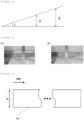
- the electrode assembly which has many stacked electrodes and has the overall length of 400 mm or more, is greatly affected by a difference in expansion ratio between the negative electrode and the positive electrode, there may occur a great problem caused by the bending situation in which the electrode assembly is sagged or warped.
- a distance from a horizontal line increases as a distance from a reference point increases even though an angle c has a constant value. That is, when a distance from the horizontal line to an end of the electrode assembly is a in case that the small-scale electrode assembly is sagged or warped by an angle c, a distance from the horizontal line to an end of a large-scale electrode assembly is b under the same condition. That is, it can be seen that the distance from the horizontal line to the end of the electrode assembly is long in the case of the large-scale electrode assembly. This means that the large-scale electrode assembly may have a greater problem caused by the bending situation.
- the electrode assembly with a large size may have a relatively greater problem caused by the bending situation than the electrode assembly with a small size.
- the electrode assembly is manufactured to be flat by being heated and pressed in order to solve the above-mentioned problem, the large number of stacked electrodes may cause contraction and expansion of the electrode assembly, which causes a limitation.
- the secondary battery may not be bent after the activation process.
- the negative electrode includes a silicon-based active material.
- the silicon-based active material may include at least one of a silicon-carbon composite and a silicon oxide.
- the silicon-based active material may include a silicon carbon composite, a silicon oxide, or both the silicon carbon composite and the silicon oxide.
- the silicon-based oxide is a material including SiOx (0 ⁇ x ⁇ 2).
- the negative electrode may additionally include a carbon-based active material. Graphite may be used as the carbon-based active material.
- the negative electrode may include the silicon-based active material of 1 to 40 parts by weight, 2 to 30 parts by weight, 3 to 15 parts by weight, or 4 to 10 parts by weight based on 100 parts by weight of an active material.
- the negative electrode may include a negative electrode current collector; and a negative electrode active material layer positioned on at least one surface of the negative electrode current collector and including a negative electrode active material, a binder, and a conductive material.
- the negative electrode active material layer includes a lower layer region being in surface contact with the negative electrode current collector, and an upper layer region being in surface contact with the lower layer region and extending to a surface of the negative electrode active material layer.
- At least one of the lower layer region and the upper layer region may include a silicon-based active material.
- Both the lower and upper layer regions may include a silicon-based active material, as necessary.
- At least one of the lower and upper layer regions may further include a carbon-based active material.
- the "surface contact” means a shape in which the surfaces adjoin each other.
- the separator may include a porous substrate, and an organic/inorganic composite porous coating layer formed on at least one surface of the porous substrate. Because the separator of the electrode assembly according to the present invention needs to have the bonding force with respect to the negative electrode, one surface of the separator may be a surface that adjoins the negative electrode.
- the separator may include a porous substrate, and an organic/inorganic composite porous coating layer provided on at least one of one surface and the other surface of the porous substrate. That is, one of the two opposite surfaces of the separator may be a surface that adjoins the negative electrode, and the other surface of the separator may be a surface that adjoins the positive electrode.
- the separator may have bonding forces with respect to the negative and positive electrodes.
- the organic/inorganic composite porous coating layer may include one or more types of particulate binder resins and one or more types of inorganic particles.
- FIG. 1 schematically illustrates a cross-section of the separator according to the specific embodiment of the present invention.
- a separator 10 includes a porous substrate 1, and an organic/inorganic composite porous coating layer 2 formed on at least one surface of the porous substrate.
- FIG. 1 illustrates that the organic/inorganic composite porous coating layer 2 is formed only on one surface of the porous substrate 1.
- the organic/inorganic composite porous coating layer 2 of the separator of the present invention may also be formed on the other side surface of the porous substrate 1.
- the organic/inorganic composite porous coating layer 2 includes particulate binder resins 4 and 5 and inorganic particles 3.
- the particulate binder polymers 4 and 5 may be a fluorine-based polymer 4 and an acrylic-based polymer 5.
- the particulate binder resin may include an acrylic-based polymer and a fluorine-based polymer.
- a weight ratio between the acrylic-based polymer and the fluorine-based polymer may be 20:80 to 60:40.
- the fluorine-based polymer may affect the wet bonding force.
- a surface of the separator may serve as a bonding layer with respect to the electrode. In case that the acrylic-based polymer is excessively present on the surface of the separator, the wet bonding force may be reduced.
- the acrylic-based polymer has a particle diameter of 350 to 450 nm and a density of 1.4 to 1.6 and the fluorine-based polymer has a particle diameter of 250 to 400 nm and a density of 1.6 to 1.8
- emulsion particle sizes and density differences make it easier for the acrylic-based polymers to move to the surface of the separator during the movement on the surface by migration. Therefore, as described above, the content of the acrylic-based polymer may be adjusted to 60 parts by weight or less.
- the dry bonding force decreases, the bonding force is strongly maintained between the positive electrode and the separator, and the bonding force between the negative electrode and the separator relatively decreases, which may cause a defect caused by bending.
- the fluorine-based polymer may be a homopolymer of polyvinylidene fluoride (PVDF), a copolymer of polyvinylidene fluoride with another polymerizable monomer, or a mixture of two or more thereof.
- PVDF polyvinylidene fluoride
- the fluorine-based polymer may be a homopolymer of polyvinylidene fluoride (PVDF), a copolymer of polyvinylidene fluoride with another polymerizable monomer, or a mixture of two or more thereof.
- examples of another monomer polymerizable with vinylidene fluoride may include, but not limited to, one or more materials selected from a group consisting of tetrafluoroethylene, hexafluoropropylene, trifluoroethylene, chlorofluoroethylene, 1,2 difluoroethylene, perfluoro (methylvinyl) ether, perfluoro (ethylvinyl) ether, perfluoro (propylvinyl) ether, perfluoro (1,3-dioxol), perfluoro (2,2-dimethyl-1,3-dioxol), trichloroethylene, and vinyl fluoride.
- the fluorine-based polymer may be a copolymer (PVdF-HFP) of vinylidene fluoride and hexafluoropropylene (HFP).
- the content of another monomer polymerizable with vinylidene fluoride may be 1 to 20 weight%, particularly 3 to 18 weight% of the copolymer.
- Another polymerizable monomer serves to increase the wet bonding force. In case that the content of the monomer is less than 1 weight%, the wet bonding force may be hardly generated. In case that the content exceeds 1 weight%, the resistance of the separator is excessively increased, which may degrade the performance of the electrode assembly.
- the difference between the dry bonding force and the wet bonding force of the separator with respect to the negative electrode is larger than the difference between the dry bonding force and the wet bonding force of the separator with respect to the positive electrode, which may cause bending.
- the bonding force between the separator and the electrode is excessively high, the binder of the separator hinders diffusion and wettability of the electrolyte, which may degrade electrolyte impregnation and increase internal resistance.
- the acrylic-based polymer may particularly be a (meth)acrylic acid ester-styrene copolymer or an acrylic-styrene copolymer.
- specific examples of (meth)acrylic acid ester may include (meth)acrylic acid methyl, (meth)acrylic acid ethyl, (meth)acrylic acid n-propyl, (meth)acrylic acid i-propyl, (meth)acrylic acid n-butyl, (meth)acrylic acid i-butyl, (meth)acrylic acid n-amyl, (meth)acrylic acid i-amyl, (meth)acrylic acid hexyl, (meth)acrylic acid cyclohexyl, (meth)acrylic acid 2-ethylhexyl, (meth)acrylic acid n-octyl, (meth)acrylic acid nonyl, (meth)acrylic acid decy
- At least one selected from (meth)acrylic acid methyl, (meth)acrylic acid ethyl, (meth)acrylic acid butyl, and (meth)acrylic acid 2-ethylhexyl is preferred, and (meth)acrylic acid butyl is particularly preferred.
- the acrylic-styrene copolymer may include an acrylic-based binder, and the acrylic-based binder may be a polyacrylate-based binder.
- the binder may be one or more materials selected from a group consisting of styrene-butadiene rubber, nitrile-butadiene rubber, acrylonitrile-butadiene rubber, acrylonitrile-butadiene-styrene rubber, and acrylate-based polymers, and more particularly, the binder may be a copolymer including acrylate.
- the acrylic-based polymer may be a (meth)acrylic acid ester-styrene copolymer, and the styrene may account for 50 to 80 parts by weight based on 100 parts by weight of the comonomer that constitutes the acrylic-based polymer.
- Styrene has a relatively higher crystalline and Tm (melting temperature) than (meth)acrylic acid ester, e.g., butyl acrylate, which may affect the dry bonding force when styrene is included within a predetermined content range during copolymerization.
- Tg decreases, and melt-deformation of the acrylic-based polymer occurs during the process of drying the separator, such that the dry bonding force may not be as expected.
- styrene exceeds 80 parts by weight, the crystalline is high, and styrene becomes relatively less sticky even though the shape of the acrylic-based polymer is maintained.
- a glass transition temperature (Tg) of the acrylic-based polymer particle may be 40 to 60°C.
- the inorganic particle may be Al 2 O 3 .
- a modulus of the separator measured based on a supply direction (machine direction (MD) of the separator is 4,000 kgf/cm 2 or more and less than 10,000 kgf/cm 2 or 5,000 kgf/cm 2 or more and less than 8,000 kgf/cm 2 .
- a coefficient of kinetic friction of the separator is more than 0.1 and 0.35 or less, 0.15 to 0.33, or 0.2 to 0.3.
- FIG. 5 is a view schematically illustrating the separator according to the present invention.
- a direction perpendicular to a short side w of the separator 14, i.e., a length of a long side of the separator 14 corresponds to the supply direction MD of the separator 14.
- the separator may have the modulus and the coefficient of kinetic friction.
- the modulus and the coefficient of kinetic friction may not only affect the wet or dry bonding force with respect to the positive electrode or the negative electrode but also reduce the occurrence of creases on the separator or a misalignment defect during the process of stacking the electrode assemblies.
- the reduction in the above-mentioned problems is further required when the size of the electrode assembly increases, like the high-capacity electrode assembly. Therefore, it is possible to provide the electrode assembly with the uniform and excellent performance by preventing the high-capacity electrode assembly from being creased and maintaining the alignment of the high-capacity electrode assembly.
- a length of the short side of the separator may be 500 mm or more, particularly 600 mm or more.
- the length of the short side of the separator may be a length of the long side based on the electrode assembly. That is, the length of the short side of the separator means a length in a direction perpendicular to the supply direction of the separator.
- the length of the short side of the porous substrate is equal to the length of the short side of the separator, and the length of the short side of the separator means a side perpendicular to the supply direction (machine direction (MD)) of the separator.
- the short side may be expressed as a width.
- the modulus of the separator may be a value measured in the supply direction (machine direction (MD)) of the separator.
- the magnitude of the modulus of the separator measured in the supply direction (machine direction (MD)) of the separator may be 4,000 to 30,000 kgf/cm 2 , particularly 5,000 to 30,000 kgf/cm 2 , and more particularly 5,500 to 28,000 kgf/cm 2 .
- the modulus of the separator a separator specimen having a width of 15 mm and a length of 15 cm was prepared, and a tensile test was performed on the separator specimen by using a universal testing machine (UTM). More specifically, the test was performed by setting a speed condition of the universal testing machine to 50 mm/min. The modulus was measured by using a load applied when the separator specimen is deformed by 2% in a longitudinal direction. That is, in this case, the longitudinal direction means the direction MD of the separator, and the width means the length of the short side of the separator.
- a coefficient of kinetic friction of the separator may be more than 0.1 and 0.35 or less, e.g., 0.2 or more and 0.3 or less.
- the coefficient of kinetic friction of the separator may be measured on the separator specimen by using a 14FW friction/abrasion measurer of Heidon.
- the friction/abrasion measurer used a diamond pin with 0.1 mm R, and the coefficient of kinetic friction was measured on the separator under a condition of a weight of 5g at 50 mm/min.
- the electrode assembly with the excellent performance may be manufactured by using the separator. Specifically, it is possible to prevent the occurrence of creases on the separator or the misalignment defect when the separators are supplied during the process of stacking the separators while supplying the separators onto a stack table. Therefore, it is possible to manufacture the electrode assembly with the uniform and excellent performance.
- a thickness of the organic/inorganic composite porous coating layer may be 2 to 5 ⁇ m. In case that the thickness range of the coating layer is satisfied, it is possible to easily ensure the modulus and coefficient of kinetic friction of the separator according to the present invention.
- the porosity of the porous substrate may be 20 to 60%, particularly 25 to 55%.
- a pore size of the porous substrate may be 20 to 25 nm.
- the compressibility of the porous substrate may be less than 10%, particularly less than 8%.
- the compressibility was measured by heating and pressing the porous substrate at a temperature of 70°C and a pressure of 4 MPa for one second and calculating a change in thicknesses between after the heating and pressing. That is, the calculation was performed on the basis of Equation 1 below.
- Compressibility (%) [(Porous substrate thickness before heating and pressing - Porous substrate thickness after heating and pressing)/Porous substrate thickness before heating and pressing] X 100 (%)
- the magnitude of the modulus according to the present invention may be obtained.
- the compressibility may also be referred to as a thickness deformation rate.
- the embodiment of the present invention provides the secondary battery that satisfies Expression 1 below.
- X represents a maximum distance measured from an imaginary reference line, which connects two opposite sides of an upper surface of the secondary battery, to a lowest point of the upper surface of the secondary battery in a state in which the secondary battery is placed on a flat surface so that a concave surface of the secondary battery is directed upward after the activation process of the secondary battery.
- the measurement is performed in a state in which any one surface of the secondary battery is directed upward.
- the configuration in which Expression 1 is satisfied means that the secondary battery is not bent after the activation of the secondary battery. That is, as illustrated in FIG. 4 , one surface of the secondary battery has a partially concave shape after the activation process of the secondary battery. In this case, as illustrated in FIG. 4 , the maximum distance is measured from the imaginary reference line, which connects two opposite sides of the upper surface of the secondary battery, to the lowest point of the upper surface of the secondary battery in the state in which the secondary battery is placed on the flat surface so that the concave surface of the secondary battery is directed upward.
- a ruler a one flat ruler (hereinafter, referred to as a ruler a) is placed on two opposite sides of the upper surface of the secondary battery, and the maximum distance to the lowest point of the upper surface of the secondary battery is measured by using a separate flat ruler (hereinafter, referred to as a ruler b).
- a ruler b a separate flat ruler
- FIG. 4(a) illustrates a case in which bending occurs
- FIG. 4(b) illustrates a case in which no bending occurs.
- the electrode assembly may not be bent after the activation process.
- the electrode assembly which is taken out of the opened battery casing, may not be bent after the activation process.
- the step of activating the secondary battery may include degassing after charging the secondary battery one or more times, e.g., two or three times under a condition of a temperature of 25 to 60°C, a pressure of 0.1 to 0.9 Mpa, a current of 0.2 to 0.8 C, e.g., 0.3 to 0.7 C, 0.4 to 0.6 C or 0.5C, and a state of charge (SOC) of 30 to 60%.
- the condition of the activation step may also affect the wet or dry bonding force between the separator and the positive or negative electrode.
- the activation step may be performed in a state in which the secondary battery is pressed by the jig. Because the activation is performed in the state in which the secondary battery is pressed by the jig, the bending may be minimized even without the jig under the charging/discharging condition after the activation step.
- the pressure is excessive, there may occur a problem in that lithium precipitation occurs because of binder resistance caused by great bonding.
- the heat press step includes a lower plate configured to apply heat and configured such that the electrode assembly to be heated and pressed is placed on the lower plate, and an upper plate corresponding to the lower plate and configured to apply heat.
- the lower and upper plates may be a pair of pressing blocks.
- the step of supplying the separator onto the stack table may include a step of unwinding the separator wound around a separator roll, and a step of pressing the separator with pressure of 0.1 kgf/cm 2 or less.
- the separator may be pressed by a separator dancer part to be described below.
- the electrode assembly manufacturing apparatus may include a separator supply part configured to supply the separator onto the stack table, a positive electrode supply part configured to supply the positive electrode onto the stack table, and a negative electrode supply part configured to supply the negative electrode onto the stack table.
- the heat press part includes the pair of pressing blocks, and the pair of pressing blocks surface-presses the stack while moving in the direction in which the pair of pressing blocks faces each other.
- the heat press part includes the pair of pressing blocks, and the press heaters configured to heat the pressing blocks.
- the press heaters heat the pressing blocks, and the pair of pressing blocks moves in the direction in which the pair of pressing blocks face each other, thereby surface-pressing the stack placed between the pressing blocks.
- the pair of pressing blocks may include the press heaters therein.
- the heat press part may include two heat press parts separated from each other. That is, the heat press part may include a first heat press part and a second heat press part.
- the first heat press part may include a pair of first pressing blocks. Pressing surfaces of the pair of first pressing blocks may include grooves corresponding in shape to the gripper so that the pair of first pressing blocks may press the stack in the state in which the gripper grips the stack. A portion of the pressing surface, which excludes the groove, may be a flat surface.
- the second heat press part may include a pair of second pressing blocks. Pressing surfaces of the pair of second pressing blocks may be configured as flat surfaces. That is, when the stack is placed on the pressing surfaces of the pressing blocks, the second pressing blocks may heat and press the stack while moving toward each other.
- the heat press part when the heat press part is divided into two parts, the heat press part is cooled while the heated stack is transferred, such that it is possible to prevent a loss of a bonding force between layers in the stack.
- the condition in which the heat press part heats and presses the stack is identical to the above-mentioned condition of the heat press step.
- the electrode assembly manufacturing apparatus may include the gripper configured to grip the stack during the process of transferring the stack from the stack table to the heat press part.
- the gripper may grip or release the stack in the above-mentioned manner.
- part means an interface that performs a particular function in the apparatus for manufacturing an electrode assembly.
- the stack table may include a table body on which the stack is placed, and a drive part configured to operate the table body.
- the table body may include a stack table heater capable of heating the stack to a predetermined temperature when the stack is placed on the table body.
- the positive electrode supply part may include at least one of a positive electrode seating table, a positive electrode roll, a first cutter, a first conveyor belt, and a positive electrode supply head.
- the positive electrode seating table may include a positive electrode heater configured to heat the positive electrode, which is placed on the positive electrode seating table, to a predetermined temperature.
- the negative electrode supply part may include at least one of a negative electrode seating table, a negative electrode roll, a second cutter, a second conveyor belt, and a negative electrode supply head.
- the negative electrode seating table may include a negative electrode heater configured to heat the negative electrode, which is placed on the negative electrode seating table, to a predetermined temperature.
- a positive electrode stacking part may include a first suction head configured to hold the positive electrode, which is seated on the positive electrode seating table, by vacuum suction.
- the positive electrode stacking part may move the positive electrode from the positive electrode seating table to the stack table.
- the negative electrode stacking part may include a second suction head configured to hold the negative electrode, which is seated on the negative electrode seating table, by vacuum suction.
- the negative electrode stacking part may move the negative electrode from the negative electrode seating table to the stack table.
- the current collector, the active material, the conductive material, and the like used for the positive and negative electrodes may be used without limitation as long as the current collector, the active material, the conductive material, and the like are those publicly-known in the art. Further, a method publicly-known in the art may be used as the method of manufacturing the positive and negative electrodes without limitation.
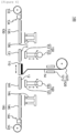
- FIG. 6 is a cross-sectional view illustrating a process flow of the electrode assembly manufacturing apparatus according to the embodiment of the present invention
- FIG. 7 is a plan view illustrating the process flow of the electrode assembly manufacturing apparatus according to the embodiment of the present invention.
- a holding device 170, a heat press part 180, and an induction heating part 190 illustrated in FIG. 7 are omitted from FIG. 6
- a separator supply part 120 illustrated in FIG. 6 is omitted from FIG. 7 .
- an electrode assembly manufacturing apparatus 100 includes the separator supply part 120 configured to supply the separator 14 onto a stack table 110, a positive electrode supply part 130 configured to supply a positive electrode 11 onto the stack table 110, and a negative electrode supply part 140 configured to supply a negative electrode 12 onto the stack table 110.
- the separator 14, the positive electrode 11, and the negative electrode 12 may be supplied onto the stack table 110 while being heated by the positive electrode supply part 130 and the negative electrode supply part 140.
- the electrode assembly manufacturing apparatus 100 includes a positive electrode stacking part 150 configured to stack the positive electrode 11, which is supplied by the positive electrode supply part 130, on the stack table 110, and a negative electrode stacking part 160 configured to stack the negative electrode 12, which is supplied by the negative electrode supply part 140, on the stack table 110.
- the separators 14, which are supplied by the separator supply part 120 are stacked in a zigzag manner while alternately reciprocating to the left side of the stacking axis and the right side of the stacking axis based on the stacking axis.
- any one of the positive and negative electrodes 11 and 12 is alternately inserted into the space (between the separators) defined when the separator 14 is folded.
- the stack in which the positive electrode 11, the separator 14, the negative electrode 12, and the separator 14 are repeatedly stacked, is placed on the stack table 110.
- the separator supply part 120 may include a separator heating part 121 and a separator roll 122.
- the separator heating part 121 may be selectively applied.
- the negative electrode supply part 140 may include a negative electrode seating table 141, a negative electrode heater 142, a negative electrode roll 143, a second cutter 144, a second conveyor belt 145, and a negative electrode supply head 146.
- the negative electrode heater 142 may be selectively applied.
- the positive electrode stacking part 150 stacks the positive electrode 11 on the stack table 110.
- the positive electrode stacking part 150 may include a first suction head 151, a first head heater (not illustrated), and a first movement part 153.
- the negative electrode stacking part 160 stacks the negative electrode 12 on the stack table 110.
- the negative electrode stacking part 160 may include a second suction head 161, a second head heater (not illustrated), and a second movement part 163.
- the electrode assembly manufacturing apparatus 100 may further include the holding device 170 configured to fix the positive electrode 11 and the negative electrode 12 when the positive electrode 11 and the negative electrode 12 are stacked on the stack table 110.
- the electrode assembly manufacturing apparatus 100 according to the embodiment of the present invention includes the heat press part 180 configured to bond the positive electrode 11, the separator 14, and the negative electrode 12 by heating and pressing the stack placed on the stack table 110.
- the electrode assembly manufacturing apparatus 100 further includes the induction heating part 190 configured to transfer heat to the electrode in the stack by heating the stack by induction heating.
- the electrode assembly manufacturing apparatus may further include a controller (not illustrated) configured to control whether to operate the induction heating part 190. Therefore, an electrode assembly 10 illustrated in FIG. 7 may be finally manufactured.
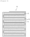
- FIG. 8 is a cross-sectional view exemplarily illustrating an electrode assembly manufactured by the electrode assembly manufacturing apparatus and the electrode assembly manufacturing method according to the embodiment of the present invention.
- the electrode assembly 10 may be provided in the form in which the separators, which are stacked while being folded in a zigzag manner, and the positive or negative electrodes, which are inserted into the spaces between the separators, are alternately inserted and stacked.
- the separator 14 may surround an outermost periphery of the stack of the electrode assembly 10.
- the configuration of the electrode assembly 10 is not limited to the example illustrated in FIG. 8 .
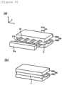
- FIG. 9 illustrates a configuration of a heat press 50, particularly a case in which a heat press part 50 includes the first heat press part 50 and the second heat press part 60.
- FIG. 9(a) is a perspective view illustrating the first heat press part 50
- FIG. 9(b) is a perspective view illustrating the second heat press part 60.
- the first heat press part 50 may heat and press a stack S in a state in which the stack S is fixed by a gripper 51.
- the first heat press part 50 may include a pair of first pressing blocks 50a and 50b. All the pressing surfaces of the pair of first pressing blocks 50a and 50b may be provided as flat surfaces, except for grooves corresponding to fixing parts 51b of the gripper 51.
- the gripper 51 may include: a main body 51a provided to correspond to a length x and a height y of the stack S or larger than the length x and the height y of the stack S, and the fixing parts 51b protruding from the main body 51a and configured to hold the stack S.
- the length x of the stack S may mean a longest distance between one end and the other end of the stack S.
- the height y may mean a distance in a stacking direction of the stack S.
- a width z may mean a distance traversing the upper surface of the stack S.
- the position of the fixing part 51b may be adjusted in the height direction of the main body 51a.
- the fixing part 51b may fix the stack S by coming into contact with the upper and lower surfaces of the stack S.
- the pair of first pressing blocks 50a and 50b heats and presses the stack S while moving in a direction in which the pair of first pressing blocks 50a and 50b faces each other.
- the electrodes and the separators in the electrode assembly are stably joined by being heated and pressed.
- the first heat press part 50 may be configured to compensate for a configuration in which the electrode assembly induction-heated is cooled while moving, and the first heat press part 50 may be selectively provided. That is, in some instances, the first heat press part may be omitted.
- the second heat press part 60 may finally heat and press the stack S primarily heated and pressed by the first heat press part 50.
- the second heat press part 60 may include a pair of second pressing blocks 60a and 60b, and a pair of pressing blocks 61 and 62 may press surfaces of the stack S while moving in a direction in which the pair of pressing blocks 61 and 62 faces each other.
- all the pressing surfaces of the pair of second pressing blocks 60a and 60b included in the second heat press part 60, which come into contact with and press the stack S, may be provided as flat surfaces.
- the dry bonding force with respect to the negative electrode of the electrode assembly and the dry bonding force with respect to the positive electrode were measured by preparing a specimen in the form of a stack made by stacking a positive electrode, a separator, and a negative electrode and cutting a part of the electrode assembly into a size of 20 mm X 70 mm, and peeling the separator off the specimen at a rate of 100 mm/min from one side of the separator in a 90° peeling mode by using a tensile tester (UTM equipment) before the electrode assembly was impregnated with an electrolyte.
- UDM equipment tensile tester
- a specimen in the form of a stack made by stacking a positive electrode, a separator, and a negative electrode was prepared by taking an electrode assembly out of a pouch exterior material of a secondary battery after the activation process and cutting a part of the electrode assembly (impregnated with the electrolyte) into a size of 20 mm X 70 mm.
- the wet bonding force of the electrode assembly was measured by peeling the separator off the specimen from one side of the separator at a rate of 100 mm/min in a 90° peeling mode by using a tensile tester (UTM equipment).
- UDM equipment tensile tester
- the electrode assembly was taken out of the pouch exterior material of the secondary battery after the activation process, the electrode assembly was impregnated with a dimethyl carbonate solvent for 30 minutes in order to remove electrolyte additives or metal salt components remaining on the surface of the separator, the separator was dried for 24 hours under a room temperature condition, and the surface of the separator was observed and the surface composition was measured on the basis of the above-mentioned method.
- Tables 1 to 3 The result is shown in Tables 1 to 3 below.
- the secondary battery including the electrode assembly was placed on a flat surface so that the concave surface of the secondary battery is directed upward.
- a ruler a one flat ruler
- a ruler b one flat ruler
- Tables 1 to 3 For reference, in case that the measured distance is less than 5 mm at most, it is determined that no bending occurs.
- the electrode assembly was taken out of the pouch exterior material of the secondary battery after the activation process, the electrode assembly was impregnated with a dimethyl carbonate solvent for 30 minutes in order to remove electrolyte additives or metal salt components remaining on the surface of the separator, the separator was dried for 24 hours under a room temperature condition, and resistance properties of the separator were identified.
- the separator was cut and placed on a 2032 coin cell of Hoshen, and the resistance value at the time of impregnating the separator with the electrolyte was measured by an alternating current method at 25°C with electrochemical impedance spectroscopy (EIS) by using a 1M LiPF6-ethylene carbonate/ethyl methyl carbonate (weight ratio 3:7) electrolyte.
- EIS electrochemical impedance spectroscopy
- the modulus of the separator was measured. Specifically, the separator specimen having a width of 15 mm and a length of 15 cm in the direction MD of the separator was prepared, and the tensile test was performed on the separator specimen by using the universal testing machine (UTM). More specifically, the test was performed by setting a speed condition of the universal testing machine to 50 mm/min. The modulus was measured by using a load applied when the separator specimen is deformed by 2% in a longitudinal direction.
- the separator specimen having a width of 5 cm and a length of 5 cm in the direction MD of the separator was prepared, and the separator specimen was measured by using the 14FW friction/abrasion measurer of Heidon.
- the friction/abrasion measurer used a diamond pin with 0.1 mm R, and the coefficient of kinetic friction was measured on the separator under a condition of a weight of 5g at 50 mm/min.
- the contraction ratio of the separator was measured and evaluated. Specifically, the thermal contraction ratio of the separator was measured at 130°C, and when any one of the directions MD and TD had the thermal contraction ratio of more than 5%, it was determined that a defect and deterioration occurred.
- a specific surface area of the carbon nanotube (CNT) was 550 m 2 /g.
- the carbon nanotubes (CNT) were multi-walled carbon nanotubes.
- the bonding force to the positive electrode means the bonding force of the separator with respect to the positive electrode
- the bonding force to the negative electrode means the bonding force of the separator with respect to the negative electrode
- a binder with low specific gravity needs to move to the surface at the time of drying the slurry of the separator, and when the inorganic particles are uniform in shape, the binder easily moves.
- Comparative Example 6 because the inorganic particles having large aspect ratios were randomly distributed, it was difficult for the binder to move to the surface by being hindered by the particles at the time of drying the slurry (deterioration in migration of the binder), and the dry bonding force of the separator with respect to the positive electrode and the wet bonding force of the separator with respect to the negative electrode were very low.
- the electrode assembly of the present application is not bent, the position of the electrode may be aligned and fixed without being distorted, such that the energy density may be improved, and the electrode assembly and the secondary battery including the same may be in excellent in performance.
- FIG. 10 it can be seen that the separator of the electrode assembly of Example 1 was not creased.
- FIG. 11 it can be seen that the separator of the electrode assembly in Comparative Example 14 was creased.
- a horizontal line is formed on a middle portion, and the line means a crease.
Landscapes
- Chemical & Material Sciences (AREA)
- Chemical Kinetics & Catalysis (AREA)
- Electrochemistry (AREA)
- General Chemical & Material Sciences (AREA)
- Engineering & Computer Science (AREA)
- Inorganic Chemistry (AREA)
- Manufacturing & Machinery (AREA)
- Materials Engineering (AREA)
- Composite Materials (AREA)
- Cell Separators (AREA)
- Secondary Cells (AREA)
- Battery Electrode And Active Subsutance (AREA)
Applications Claiming Priority (5)
| Application Number | Priority Date | Filing Date | Title |
|---|---|---|---|
| KR20220177177 | 2022-12-16 | ||
| KR20220177156 | 2022-12-16 | ||
| KR20220177190 | 2022-12-16 | ||
| KR1020230181456A KR102885717B1 (ko) | 2022-12-16 | 2023-12-14 | 전극 조립체 및 이를 포함하는 이차 전지 |
| PCT/KR2023/020757 WO2024128853A1 (ko) | 2022-12-16 | 2023-12-15 | 전극 조립체 및 이를 포함하는 이차 전지 |
Publications (2)
| Publication Number | Publication Date |
|---|---|
| EP4489207A1 true EP4489207A1 (de) | 2025-01-08 |
| EP4489207A4 EP4489207A4 (de) | 2025-12-03 |
Family
ID=91486174
Family Applications (1)
| Application Number | Title | Priority Date | Filing Date |
|---|---|---|---|
| EP23904052.0A Pending EP4489207A4 (de) | 2022-12-16 | 2023-12-15 | Elektrodenanordnung und sekundärbatterie damit |
Country Status (6)
| Country | Link |
|---|---|
| US (1) | US20260058215A1 (de) |
| EP (1) | EP4489207A4 (de) |
| JP (1) | JP7801482B2 (de) |
| KR (1) | KR102885717B1 (de) |
| CA (1) | CA3254334A1 (de) |
| WO (1) | WO2024128853A1 (de) |
Families Citing this family (1)
| Publication number | Priority date | Publication date | Assignee | Title |
|---|---|---|---|---|
| WO2026035040A1 (ko) * | 2024-08-06 | 2026-02-12 | 주식회사 엘지에너지솔루션 | 리튬 이차전지용 분리막과 이의 제조 방법 및 이를 포함하는 리튬 이차전지과 이의 제조 방법 |
Family Cites Families (12)
| Publication number | Priority date | Publication date | Assignee | Title |
|---|---|---|---|---|
| KR20130132230A (ko) | 2012-05-25 | 2013-12-04 | 주식회사 엘지화학 | 단차를 갖는 전극 조립체 및 이를 포함하는 전지셀, 전지팩 및 디바이스 |
| KR20150106808A (ko) * | 2013-11-21 | 2015-09-22 | 삼성에스디아이 주식회사 | 이차 전지 및 이의 제조 방법 |
| PL3352248T3 (pl) * | 2016-04-01 | 2020-06-29 | Lg Chem, Ltd. | Separator zawierający warstwę adhezyjną dla urządzenia elektrochemicznego i zespół elektrod go zawierający |
| KR101964056B1 (ko) * | 2016-09-22 | 2019-04-03 | 더블유스코프코리아 주식회사 | 리튬이차전지용 폴리올레핀 분리막 다층 필름 및 이의 제조방법 |
| JP7095685B2 (ja) * | 2017-03-31 | 2022-07-05 | 日本ゼオン株式会社 | 非水系二次電池接着層用スラリー組成物、製造方法及び用途 |
| JP7301268B2 (ja) | 2017-05-12 | 2023-07-03 | パナソニックホールディングス株式会社 | 非水電解質二次電池 |
| JP7054997B2 (ja) * | 2017-08-03 | 2022-04-15 | 帝人株式会社 | 非水系二次電池用セパレータ、非水系二次電池、非水系二次電池用セパレータの製造方法、および、非水系二次電池用コーティング組成物 |
| JP7217297B2 (ja) * | 2018-06-26 | 2023-02-02 | シェンチェン シニア テクノロジー マテリアル カンパニー リミテッド | 複合リチウム電池セパレータ及びその調製方法 |
| KR102716984B1 (ko) * | 2019-03-08 | 2024-10-15 | 주식회사 엘지에너지솔루션 | 전극과의 건식 접착력이 개선된 분리막 및 이를 이용한 리튬 이차전지의 제조 방법 |
| KR102477643B1 (ko) * | 2019-05-09 | 2022-12-13 | 주식회사 엘지에너지솔루션 | 전기화학소자용 분리막 및 이를 포함하는 전기화학소자 |
| JP7588094B2 (ja) * | 2019-12-26 | 2024-11-21 | 三洋電機株式会社 | 二次電池、及びその製造方法 |
| KR20220155838A (ko) * | 2021-05-17 | 2022-11-24 | 삼성에스디아이 주식회사 | 이차전지용 분리막 및 이를 포함하는 이차전지 |
-
2023
- 2023-12-14 KR KR1020230181456A patent/KR102885717B1/ko active Active
- 2023-12-15 WO PCT/KR2023/020757 patent/WO2024128853A1/ko not_active Ceased
- 2023-12-15 EP EP23904052.0A patent/EP4489207A4/de active Pending
- 2023-12-15 US US18/854,916 patent/US20260058215A1/en active Pending
- 2023-12-15 JP JP2024556628A patent/JP7801482B2/ja active Active
- 2023-12-15 CA CA3254334A patent/CA3254334A1/en active Pending
Also Published As
| Publication number | Publication date |
|---|---|
| KR20240096389A (ko) | 2024-06-26 |
| JP2025511607A (ja) | 2025-04-16 |
| KR102885717B1 (ko) | 2025-11-14 |
| WO2024128853A1 (ko) | 2024-06-20 |
| JP7801482B2 (ja) | 2026-01-16 |
| US20260058215A1 (en) | 2026-02-26 |
| EP4489207A4 (de) | 2025-12-03 |
| CA3254334A1 (en) | 2025-07-03 |
Similar Documents
| Publication | Publication Date | Title |
|---|---|---|
| EP2605312B1 (de) | Poröse membran für eine sekundärbatterie, herstellungsverfahren dafür und deren verwendung | |
| EP3379602B1 (de) | Separator für stromspeichervorrichtungen, elektrodenkörper damit und stromspeichervorrichtung | |
| KR101888740B1 (ko) | 비수전해질 이차 전지용 세퍼레이터 및 그 제조 방법 | |
| EP3627586B1 (de) | Separator für nichtwässrige sekundärbatterien, nichtwässrige sekundärbatterie und verfahren zur herstellung einer nichtwässrigen sekundärbatterie | |
| CN105378978A (zh) | 电极、电化学电池及形成电极和电化学电池的方法 | |
| KR20150089000A (ko) | 전극/세퍼레이터 적층체의 제조 방법 및 리튬 이온 2 차 전지 | |
| JP7831916B2 (ja) | 有機/無機複合多孔性コーティング層を含む電気化学素子用分離膜及びそれを含む電気化学素子 | |
| US12224422B2 (en) | Fabrication of lithium battery dry electrodes | |
| JP7234941B2 (ja) | 多孔性フィルム、二次電池用セパレータおよび二次電池 | |
| EP4517996A1 (de) | Separator und herstellungsverfahren dafür, sekundärbatterie, batteriemodul, batteriepack und elektrische vorrichtung | |
| US11837691B2 (en) | Battery manufacturing method | |
| EP4489207A1 (de) | Elektrodenanordnung und sekundärbatterie damit | |
| CN121617903A (zh) | 二次电池及电子装置 | |
| EP4651293A9 (de) | Elektrodenanordnung und sekundärbatterie damit | |
| US20210028496A1 (en) | Battery manufacturing method | |
| JP2025164796A (ja) | 電極、これを含む二次電池、及びこの製造方法 | |
| CN118975036A (zh) | 电极组件和包含其的二次电池 | |
| CN116936733A (zh) | 一种极片和电化学装置 | |
| JP7744080B2 (ja) | 有機/無機複合多孔性コーティング層を含む電気化学素子用分離膜及びそれを含む電気化学素子 | |
| US11605809B2 (en) | Anode active material and battery | |
| JP2003109581A (ja) | 二次電池用電極及びこれを用いた二次電池 | |
| EP4280328A1 (de) | Elektrodenanordnung für sekundärbatterie und herstellungsverfahren dafür | |
| KR20240088385A (ko) | 전극 조립체 및 전극 조립체 제조 방법 | |
| JP2025050544A (ja) | 多孔性フィルム、二次電池用セパレータ、および二次電池 | |
| WO2023145708A1 (ja) | 重合体粒子 |
Legal Events
| Date | Code | Title | Description |
|---|---|---|---|
| STAA | Information on the status of an ep patent application or granted ep patent |
Free format text: STATUS: THE INTERNATIONAL PUBLICATION HAS BEEN MADE |
|
| PUAI | Public reference made under article 153(3) epc to a published international application that has entered the european phase |
Free format text: ORIGINAL CODE: 0009012 |
|
| STAA | Information on the status of an ep patent application or granted ep patent |
Free format text: STATUS: REQUEST FOR EXAMINATION WAS MADE |
|
| 17P | Request for examination filed |
Effective date: 20241002 |
|
| AK | Designated contracting states |
Kind code of ref document: A1 Designated state(s): AL AT BE BG CH CY CZ DE DK EE ES FI FR GB GR HR HU IE IS IT LI LT LU LV MC ME MK MT NL NO PL PT RO RS SE SI SK SM TR |
|
| REG | Reference to a national code |
Ref country code: DE Ref legal event code: R079 Free format text: PREVIOUS MAIN CLASS: H01M0050460000 Ipc: H01M0004480000 |
|
| A4 | Supplementary search report drawn up and despatched |
Effective date: 20251104 |
|
| RIC1 | Information provided on ipc code assigned before grant |
Ipc: H01M 4/48 20100101AFI20251029BHEP Ipc: H01M 10/0525 20100101ALI20251029BHEP Ipc: H01M 10/0583 20100101ALI20251029BHEP Ipc: H01M 10/44 20060101ALI20251029BHEP Ipc: H01M 50/42 20210101ALI20251029BHEP Ipc: H01M 50/426 20210101ALI20251029BHEP Ipc: H01M 50/446 20210101ALI20251029BHEP Ipc: H01M 50/451 20210101ALI20251029BHEP Ipc: H01M 50/46 20210101ALI20251029BHEP Ipc: H01M 50/489 20210101ALI20251029BHEP Ipc: H01M 4/02 20060101ALN20251029BHEP |
|
| DAV | Request for validation of the european patent (deleted) | ||
| DAX | Request for extension of the european patent (deleted) |