EP4484791A2 - Träger, sperrbasisanordnung, stützrahmen und rollentragevorrichtung - Google Patents
Träger, sperrbasisanordnung, stützrahmen und rollentragevorrichtung Download PDFInfo
- Publication number
- EP4484791A2 EP4484791A2 EP24203319.9A EP24203319A EP4484791A2 EP 4484791 A2 EP4484791 A2 EP 4484791A2 EP 24203319 A EP24203319 A EP 24203319A EP 4484791 A2 EP4484791 A2 EP 4484791A2
- Authority
- EP
- European Patent Office
- Prior art keywords
- canopy
- locking
- carrier
- main body
- bracket
- Prior art date
- Legal status (The legal status is an assumption and is not a legal conclusion. Google has not performed a legal analysis and makes no representation as to the accuracy of the status listed.)
- Pending
Links
Images


Classifications
-
- B—PERFORMING OPERATIONS; TRANSPORTING
- B62—LAND VEHICLES FOR TRAVELLING OTHERWISE THAN ON RAILS
- B62B—HAND-PROPELLED VEHICLES, e.g. HAND CARTS OR PERAMBULATORS; SLEDGES
- B62B9/00—Accessories or details specially adapted for children's carriages or perambulators
- B62B9/10—Perambulator bodies; Equipment therefor
- B62B9/102—Perambulator bodies; Equipment therefor characterized by details of the seat
-
- A—HUMAN NECESSITIES
- A01—AGRICULTURE; FORESTRY; ANIMAL HUSBANDRY; HUNTING; TRAPPING; FISHING
- A01K—ANIMAL HUSBANDRY; AVICULTURE; APICULTURE; PISCICULTURE; FISHING; REARING OR BREEDING ANIMALS, NOT OTHERWISE PROVIDED FOR; NEW BREEDS OF ANIMALS
- A01K1/00—Housing animals; Equipment therefor
- A01K1/02—Pigsties; Dog-kennels; Rabbit-hutches or the like
- A01K1/0236—Transport boxes, bags, cages, baskets, harnesses for animals; Fittings therefor
- A01K1/0254—Bags or baskets
-
- A—HUMAN NECESSITIES
- A01—AGRICULTURE; FORESTRY; ANIMAL HUSBANDRY; HUNTING; TRAPPING; FISHING
- A01K—ANIMAL HUSBANDRY; AVICULTURE; APICULTURE; PISCICULTURE; FISHING; REARING OR BREEDING ANIMALS, NOT OTHERWISE PROVIDED FOR; NEW BREEDS OF ANIMALS
- A01K1/00—Housing animals; Equipment therefor
- A01K1/02—Pigsties; Dog-kennels; Rabbit-hutches or the like
- A01K1/0236—Transport boxes, bags, cages, baskets, harnesses for animals; Fittings therefor
- A01K1/0272—Boxes, bags, cages, baskets, harnesses especially adapted for transport in or on automobiles
-
- A—HUMAN NECESSITIES
- A47—FURNITURE; DOMESTIC ARTICLES OR APPLIANCES; COFFEE MILLS; SPICE MILLS; SUCTION CLEANERS IN GENERAL
- A47D—FURNITURE SPECIALLY ADAPTED FOR CHILDREN
- A47D13/00—Other nursery furniture
- A47D13/02—Baby-carriers; Carry-cots
-
- B—PERFORMING OPERATIONS; TRANSPORTING
- B60—VEHICLES IN GENERAL
- B60N—SEATS SPECIALLY ADAPTED FOR VEHICLES; VEHICLE PASSENGER ACCOMMODATION NOT OTHERWISE PROVIDED FOR
- B60N2/00—Seats specially adapted for vehicles; Arrangement or mounting of seats in vehicles
- B60N2/24—Seats specially adapted for vehicles; Arrangement or mounting of seats in vehicles for particular purposes or particular vehicles
- B60N2/26—Seats specially adapted for vehicles; Arrangement or mounting of seats in vehicles for particular purposes or particular vehicles for children
- B60N2/28—Seats readily mountable on, and dismountable from, existing seats or other parts of the vehicle
- B60N2/2842—Seats readily mountable on, and dismountable from, existing seats or other parts of the vehicle adapted to carry the child, when dismounted from the vehicle
- B60N2/2848—Seats readily mountable on, and dismountable from, existing seats or other parts of the vehicle adapted to carry the child, when dismounted from the vehicle being convertible or adaptable to a preambulator, e.g. a baby-carriage or a push-chair
-
- B—PERFORMING OPERATIONS; TRANSPORTING
- B62—LAND VEHICLES FOR TRAVELLING OTHERWISE THAN ON RAILS
- B62B—HAND-PROPELLED VEHICLES, e.g. HAND CARTS OR PERAMBULATORS; SLEDGES
- B62B7/00—Carriages for children; Perambulators, e.g. dolls' perambulators
- B62B7/04—Carriages for children; Perambulators, e.g. dolls' perambulators having more than one wheel axis; Steering devices therefor
- B62B7/06—Carriages for children; Perambulators, e.g. dolls' perambulators having more than one wheel axis; Steering devices therefor collapsible or foldable
- B62B7/08—Carriages for children; Perambulators, e.g. dolls' perambulators having more than one wheel axis; Steering devices therefor collapsible or foldable in the direction of, or at right angles to, the wheel axis
- B62B7/083—Carriages for children; Perambulators, e.g. dolls' perambulators having more than one wheel axis; Steering devices therefor collapsible or foldable in the direction of, or at right angles to, the wheel axis the wheel axes being moved from each other during folding
-
- B—PERFORMING OPERATIONS; TRANSPORTING
- B62—LAND VEHICLES FOR TRAVELLING OTHERWISE THAN ON RAILS
- B62B—HAND-PROPELLED VEHICLES, e.g. HAND CARTS OR PERAMBULATORS; SLEDGES
- B62B7/00—Carriages for children; Perambulators, e.g. dolls' perambulators
- B62B7/04—Carriages for children; Perambulators, e.g. dolls' perambulators having more than one wheel axis; Steering devices therefor
- B62B7/06—Carriages for children; Perambulators, e.g. dolls' perambulators having more than one wheel axis; Steering devices therefor collapsible or foldable
- B62B7/10—Carriages for children; Perambulators, e.g. dolls' perambulators having more than one wheel axis; Steering devices therefor collapsible or foldable by folding down the body to the wheel carriage or by retracting projecting parts into the box-shaped body
-
- B—PERFORMING OPERATIONS; TRANSPORTING
- B62—LAND VEHICLES FOR TRAVELLING OTHERWISE THAN ON RAILS
- B62B—HAND-PROPELLED VEHICLES, e.g. HAND CARTS OR PERAMBULATORS; SLEDGES
- B62B7/00—Carriages for children; Perambulators, e.g. dolls' perambulators
- B62B7/04—Carriages for children; Perambulators, e.g. dolls' perambulators having more than one wheel axis; Steering devices therefor
- B62B7/14—Carriages for children; Perambulators, e.g. dolls' perambulators having more than one wheel axis; Steering devices therefor with detachable or rotatably-mounted body
- B62B7/142—Means for securing the body to the frame
-
- B—PERFORMING OPERATIONS; TRANSPORTING
- B62—LAND VEHICLES FOR TRAVELLING OTHERWISE THAN ON RAILS
- B62B—HAND-PROPELLED VEHICLES, e.g. HAND CARTS OR PERAMBULATORS; SLEDGES
- B62B7/00—Carriages for children; Perambulators, e.g. dolls' perambulators
- B62B7/04—Carriages for children; Perambulators, e.g. dolls' perambulators having more than one wheel axis; Steering devices therefor
- B62B7/14—Carriages for children; Perambulators, e.g. dolls' perambulators having more than one wheel axis; Steering devices therefor with detachable or rotatably-mounted body
- B62B7/145—Carriages for children; Perambulators, e.g. dolls' perambulators having more than one wheel axis; Steering devices therefor with detachable or rotatably-mounted body the body being a rigid seat, e.g. a shell
-
- B—PERFORMING OPERATIONS; TRANSPORTING
- B62—LAND VEHICLES FOR TRAVELLING OTHERWISE THAN ON RAILS
- B62B—HAND-PROPELLED VEHICLES, e.g. HAND CARTS OR PERAMBULATORS; SLEDGES
- B62B9/00—Accessories or details specially adapted for children's carriages or perambulators
- B62B9/10—Perambulator bodies; Equipment therefor
- B62B9/12—Perambulator bodies; Equipment therefor involving parts that are adjustable, attachable or detachable
-
- B—PERFORMING OPERATIONS; TRANSPORTING
- B62—LAND VEHICLES FOR TRAVELLING OTHERWISE THAN ON RAILS
- B62B—HAND-PROPELLED VEHICLES, e.g. HAND CARTS OR PERAMBULATORS; SLEDGES
- B62B9/00—Accessories or details specially adapted for children's carriages or perambulators
- B62B9/10—Perambulator bodies; Equipment therefor
- B62B9/14—Equipment protecting from environmental influences, e.g. Hoods; Weather screens; Cat nets
-
- B—PERFORMING OPERATIONS; TRANSPORTING
- B62—LAND VEHICLES FOR TRAVELLING OTHERWISE THAN ON RAILS
- B62B—HAND-PROPELLED VEHICLES, e.g. HAND CARTS OR PERAMBULATORS; SLEDGES
- B62B9/00—Accessories or details specially adapted for children's carriages or perambulators
- B62B9/18—Resilient suspensions of bodies
-
- F—MECHANICAL ENGINEERING; LIGHTING; HEATING; WEAPONS; BLASTING
- F16—ENGINEERING ELEMENTS AND UNITS; GENERAL MEASURES FOR PRODUCING AND MAINTAINING EFFECTIVE FUNCTIONING OF MACHINES OR INSTALLATIONS; THERMAL INSULATION IN GENERAL
- F16F—SPRINGS; SHOCK-ABSORBERS; MEANS FOR DAMPING VIBRATION
- F16F9/00—Springs, vibration-dampers, shock-absorbers, or similarly-constructed movement-dampers using a fluid or the equivalent as damping medium
- F16F9/32—Details
- F16F9/54—Arrangements for attachment
-
- B—PERFORMING OPERATIONS; TRANSPORTING
- B62—LAND VEHICLES FOR TRAVELLING OTHERWISE THAN ON RAILS
- B62B—HAND-PROPELLED VEHICLES, e.g. HAND CARTS OR PERAMBULATORS; SLEDGES
- B62B9/00—Accessories or details specially adapted for children's carriages or perambulators
- B62B9/10—Perambulator bodies; Equipment therefor
- B62B9/14—Equipment protecting from environmental influences, e.g. Hoods; Weather screens; Cat nets
- B62B9/142—Equipment protecting from environmental influences, e.g. Hoods; Weather screens; Cat nets by flexible canopies, covers or nets
Definitions
- the present disclosure relates to a carrier and a wheeled carrying apparatus mounted with the carrier, and more particularly, to a carrier for carrying animals, a wheeled carrying apparatus mounted with the carrier, and a locking base assembly for mounting the carrier on the wheeled carrying apparatus.
- the user When traveling with an animal, the user can use a hand-held carrier to carry and move the animal.
- the carrier may be mounted on a carrying apparatus, so that it may move together with a carrying apparatus.
- the present disclosure related to a carrier.
- the carrier includes: a main body forming a carrying space; and a canopy assembly disposed to the main body of the carrier or a cloth at least partially covering the main body.
- the canopy assembly includes: a canopy; and a canopy connecting assembly disposed between the canopy and the main body or between the canopy and the cloth, so that the canopy and the main body or the cloth are detachably connected with each other.
- the canopy connecting assembly includes: a canopy frame connected to a periphery of the canopy for supporting the canopy, and detachably disposed at a periphery of an opening of the main body; and a releasing operation element disposed on the canopy frame or the bracket device sleeved outside the main body, and capable of being operated to move from a locking position to an unlocking position, so that the canopy assembly is unlocked with respect to the main body.
- the main body further includes a bracket device configured to support the main body and including a first bracket.
- the first bracket is disposed around the opening of the main body.
- the canopy connecting assembly is detachably connected to the first bracket.
- the canopy connecting assembly includes: a canopy locking device at least partially disposed on the canopy frame for cooperating with a canopy locking part correspondingly disposed on the carrier to lock the canopy assembly above the main body.
- the canopy locking device includes: a locking element mounted on the canopy frame, and is engaged with or disengaged from the canopy locking part through movement with respect to the canopy frame, so as to lock or unlock the canopy frame to the main body.
- the movement of the locking element with respect to the canopy frame is that the locking element pivots about at least one pivot point on the canopy frame to be engaged with or disengaged from the canopy locking part.
- the canopy locking device further includes the releasing operation element, and the releasing operation element operatively acts on the locking element.
- the releasing operation element When the releasing operation element is in the locking position, the locking element is engaged with the canopy locking part, and when the releasing operation element is operated to the unlocking position, the locking element is disengaged from the canopy locking part.
- the locking element is pivotably connected to the canopy frame about a pivot point and pivotably connected to the releasing operation element about another pivot point that is different from the pivot point.
- the releasing operation element is disposed on the canopy frame, is movable between the locking position and the unlocking position with respect to the canopy frame, and drives the locking element to pivot with respect to the canopy frame about the pivot point.
- the locking element has an engaging hook protruding towards the canopy locking part, and the canopy locking part comprises an engaging pin corresponding to the engaging hook.
- the engaging hook is engaged with the engaging pin, and when the releasing operation element is operated to push the locking element to pivot and be in the unlocking position, the engaging hook is disengaged from the engaging pin.
- the canopy locking device further includes an elastic restoring element, the elastic restoring element is connected between the releasing operation element and the canopy frame, and constantly provides a force for enabling the releasing operation element to be in or restored to the locking position.
- the releasing operation element is disposed on the canopy locking part and is movable between the locking position and the unlocking position with respect to the canopy locking part.
- the locking element is connected to the canopy frame and protrudes from the canopy frame to the bracket device of the carrier.
- the canopy locking part is connected with the releasing operation element to be able to move along with operation of the releasing operation element, so as to engage with or disengage from the locking element.
- the locking element is disposed as a first sheet
- the canopy locking part comprises a second sheet.
- An insertion space for accommodating the first sheet is formed between the second sheet and the releasing operation element.
- One of the first sheet and the second sheet is provided with an engaging hole
- the other of the first sheet and the second sheet is provided with an engaging protrusion that is cooperated with the engaging hole.
- the canopy locking device further includes: an elastic restoring element connected between one of the releasing operation element and the second sheet and the carrier, and constantly providing a force for enabling the releasing operation element to be in or restored to the locking position.
- the canopy locking part is disposed on the bracket device of the carri er.
- the canopy frame includes at least one pivoting section and a section position adjusting structure.
- the section position adjusting structure is configured such that the at least one pivoting section is at different angles with respect to the main body.
- the canopy frame has a triple-section folding structure.
- the canopy frame includes a first pivoting section, a second pivoting section and two locking sections, two ends of the first pivoting section are respectively pivotably connected to one ends of the two locking sections through a first pivoting part, and two ends of the second pivoting section are respectively pivotably connected to the other ends of the two locking sections through a second pivoting part, and two canopy locking devices are respectively disposed in the two locking sections, so that the two locking sections are capable of being locked to the bracket device of the carrier.
- gear teeth are disposed in each of the first pivoting part and the second pivoting part, so that the first pivoting section and the second pivoting section are able to be at different angles with respect to the locking sections.
- first pivoting part and the second pivoting part are respectively provided with a return spring to constantly bias the first pivoting part and the second pivoting part in a direction of unfolding the canopy, so as to provide assistance during unfolding of the canopy.
- a connecting structure is disposed between the canopy and the main body of the carrier.
- the connecting structure includes a connecting element and a mating connecting element.
- the connecting element is disposed at each of two sides of the main body that are opposite to each other, and the mating connecting element is disposed at each of two sides of the canopy that correspond to the connecting element and is engaged with the connecting element, so as to keep the canopy closed.
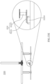
- the object may be the carrier 130.
- the carrier 130 has a box-shaped structure for carrying the animal (such as a pet) and may be mounted on the carrying frame 110 through the locking base assembly 120.
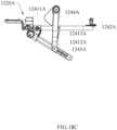
- the carrier 130 includes a grip 1330 for lifting the carrier 130 and a main body 1340 (also referred to "box body") for carrying the animal.
- a longitudinal centerline C11 of the carrier 130 and a longitudinal centerline C12 of the locking base assembly 120 are substantially on the same vertical plane, that is, the carrier 130 is substantially symmetrically disposed with respect to the longitudinal centerline C12 of the locking base assembly 120.
- a term “longitudinal centerline” refers to a centerline perpendicular to a connecting line between two ends of the grip 1330 on the carrier 130, and a direction indicated by "D11" in FIG. 1B (i.e., the longitudinal direction D11) is a longitudinal extension direction parallel to the longitudinal centerlines C11 and C12.
- FIG. 1C is a perspective view of the wheeled carrying apparatus 11 after the main body of the carrier 130 is removed
- FIG. 1D is a top perspective view of the wheeled carrying apparatus 11 after the main body is removed.
- the carrier 130 further includes a bracket device 1310 including a first bracket 1311, a second bracket 1312 and a third bracket 1313.
- the bracket device 1310 (for example, the third bracket 1313) of the carrier 130 is engaged with the locking base assembly 120, so that the carrier 130 may be stably mounted on the carrying frame 110 through the locking base assembly 120.
- the first bracket 1311 has a substantially rectangular structure, which is generally horizontally disposed at an upper end of the bracket device 1310 and is configured as an upper frame of the bracket device 1310, and is used for connecting with the grip 1330.
- the third bracket 1313 includes an engaging element 13131, two first structural reinforcement elements 13132, and a second structural reinforcement element 13133.
- the engaging element 13131 has an annular structural element (for example, a substantially rectangular annular structure).
- the two first structural reinforcement elements 13132 are respectively connected with the engaging element 13132 (for example, two ends thereof are respectively connected to two opposite long sides of the annular structural element of the engaging element 13131), and are disposed separately from each other and substantially extend in the transverse direction D12 of the carrier 130.
- the two first structural reinforcement elements 13132 are respectively disposed at a lower end of the second bracket 1312 (for example, a lower side of the U-shaped structure of the second bracket 1312), and are fixedly connected with the second bracket 1312 to play a supporting and fixing role.
- two first structural reinforcement elements 13132 may be symmetrically disposed with respect to the transverse centerline C13 of the carrier 130.
- the second structural reinforcement element 13133 is substantially vertically connected between two opposite sides (e.g., two long sides of the rectangular structure) of the annular structural element of the engaging element 13131, to enhance the impact resistance of an overall structure of the third bracket 1313.
- the third bracket 1313 may include at least one second structural reinforcement element 13133.
- FIG. 1C the two first structural reinforcement elements 13132 are respectively disposed at a lower end of the second bracket 1312 (for example, a lower side of the U-shaped structure of the second bracket 1312), and are fixedly connected with the second bracket 1312 to play a supporting and fixing role.
- two first structural reinforcement elements 13132
- the third bracket 1313 includes two second structural reinforcement elements 13133 symmetrically disposed with respect to the transverse centerline C13 of the carrier 130, providing positioning guidance to assist the carrier 130 to be locked in a substantially central position, thereby improving the stability of the carrier 130 when being mounted in the wheeled carrying apparatus 11.
- the second structural reinforcement element 13133 is spaced apart from the first structural reinforcement element 13132.
- FIG. 1D when the carrier 130 is mounted on the locking base assembly 120, there are a plurality of engagement points, for example, four engagement points. These four engaging points are generally symmetrically distributed with respect to the longitudinal centerline C11 of the carrier 130 (and the longitudinal centerline C12 of the locking base assembly 120), and symmetrically distributed with respect to the transverse centerline C13 of the carrier 130 (and the transverse centerline C14 of the locking base assembly 120). For example, these four engaging points are disposed on the locking base assembly 120 in a central symmetry. In an embodiment, a plurality of engaging points are located between two first structural reinforcement elements 13132 (as shown in FIG.
- the first structural reinforcement element in FIG. 1D is shielded by the second bracket 1312), and further, located between the first structural reinforcement element 13132 and the second structural reinforcement element 13133.
- the two second structural reinforcement elements 13133 may be provided between the structural reinforcement elements 13132, and all of the plurality of engagement points are located between the two first structural reinforcement elements 13132 and their adjacent second structural reinforcement elements 13133.
- the carrier 130 can be stably mounted on the locking base assembly 120 and the carrying frame 110 by positioning a bottom center of the carrier 130 substantially symmetrically on the locking base assembly 120, and in combination with the distribution of the plurality of engaging points of the engaging assembly 120, the user can easily place the carrier 130 symmetrically on the carrying frame 110, and optionally, can also easily place the carrier 130 to be centered, in this way, the overall stability of the wheeled carrying apparatus 11 can be improved, so that the carrying apparatus can keep balanced during driving, and also perform better impact resistance and safety.
- the carrier 130 may also be placed on the locking base assembly 120 without being centered, and the present disclosure does not limit various possible engaging positions of the carrier 130 with respect to the locking base assembly 120.
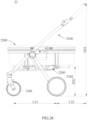
- FIG. 2 it schematically shows a carrying frame 110 according to an embodiment of the first aspect of the present disclosure.
- the carrying frame 110 of this embodiment includes a front supporting rod 1110, a rear supporting rod 1120, an upper supporting rod 1130, a handrail 1140 and a wheel set 1150.
- the wheel set 1150 includes a front wheel 1150a and a rear wheel 1150b, which are respectively connected with the front supporting rod 1110 and the rear supporting rod 1120.
- the front supporting rod 1110 may have a U-shaped structure
- the rear supporting rod 1120 may be formed by two parallel rod elements fixedly connected through a cross rod, and two ends of the front supporting rod 1110 are pivotally connected with one ends of the two rod elements of the rear supporting rod 1120, respectively.
- At least one front wheel 1150a is connected to a lower side of the front supporting rod 1110 (i.e., a lower side of the U-shaped structure), and each of the other ends of the two rod elements of the rear supporting rod 1120 are respectively connected to a corresponding rear wheel 1150b. As shown in FIG.
- two front wheels 1150a are provided, and these two front wheels 1150a are centrally symmetrically disposed and are pivotably disposed at the lower side of the front supporting rod 1110.
- the two front wheels 1150a are universal wheels, and the two rear wheels 1150b are rotatably connected to the two rod elements of the rear supporting rod 1120 and may rotate in a front-rear direction of the carrying frame 110.
- the present disclosure is not limited to the structure and number of the above-mentioned components.
- the rear supporting rod 1120 may have a U-shaped structure and then may be connected to the two rear wheels 1150b.
- the front supporting rod 1110 may also have a V-shaped or I-shaped structure, or only one front wheel 1150a may be provided.
- the front wheel 1150a may be a one-way wheel, or the rear wheel 1150b may be a universal wheel.
- a distance between the two front wheels 1150a is smaller than a distance between the two rear wheels 1150b, so as to improve the stability of the carrying frame 110 and make it easy to be rotated.
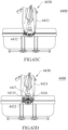
- FIG. 3A is a perspective view of the locking base assembly 120
- FIG. 3B is a side view of the locking base assembly 120
- FIG. 3C is a cross-sectional view taken along a line B-B in FIG. 3A .
- the locking base assembly 120 includes a base plate 1210, a locking mechanism and a supporting structure 1240.
- the base plate 1210 includes an upper housing and a lower housing.
- As the locking mechanism is disposed within the base plate 1210, it is shielded by the upper housing of the base plate 1210 in FIG. 3A , and its specific structure will be described in the following description of FIGS. 10A and 10B .
- the supporting structure 1240 may include two supporting frames 1241, which are respectively disposed at two transverse sides of the base plate 1210 (only one supporting frame 1241 is shown in FIG. 3A due to being shielded by the base plate 1210).
- the two supporting frames 1241 are symmetrically disposed at two sides of the base plate 1210 with respect to a longitudinal centerline C15 of the base plate 1210. It should be noted that the longitudinal centerline C15 extends in the longitudinal direction D11 as shown in FIG. 3A .
- each of the supporting frames 1241 includes a longitudinal rod 12411, a connecting rod 12412 and a shock absorbing rod 12413 connected with each other in a triangular structure.
- the longitudinal rod 12411 is disposed below the base plate 1210 and fixedly connected with the base plate 1210 (for example, its lower housing).
- a first end 12412a of the connecting rod 12412 may be pivotally connected with a first end 12411a of the longitudinal rod 12411 within a certain range (as shown in FIG.
- a second end 12412b of the connecting rod 12412 is fixedly connected with a first end 12413a of the shock absorbing rod 12413, and a second end 12413b of the shock absorbing rod 12413 is fixedly connected to a second end 12411b of the longitudinal rod 12411, for example, disposed at a middle rear section of the base plate 1210 in a longitudinal direction D11.
- the shock absorbing rod 12413 has elasticity to provide damping support for the base plate 1210.
- the shock absorbing rod 12413 is a compression spring, a hydraulic rod, a pneumatic rod or other elastic structure.
- the locking base assembly 120 may be stably disposed on the carrying frame (not shown in FIGS. 3A to 3C , and the specific arrangement thereof will be described in the following description of FIGS. 5A to 5B ), and through the shock absorbing rod 12413, the object mounted on the base plate 1210 can be buffered to a certain extent when the carrying frame is bumped.
- the upper end of the shock absorbing rod 12413 is disposed at the second end 12411b of the longitudinal rod 12411 (corresponding to the middle rear section of the base plate 1210), which has a better shock absorbing stroke, thereby achieving a better shock absorbing effect.
- the buffering capacity of the supporting frame 1241 can be adjusted by adjusting a length of the longitudinal rod 12411 to adjust the connection position of the shock absorbing rod 12413 and the longitudinal rod 12411 with respect to the base plate 1210, for example, by providing the connection position at a central position or a furthest end with respect to the base plate 1210.
- the buffering capacity of the supporting frame 1241 can be adjusted by adjusting a length of the connecting rod 12412 within a preset range, and setting an angle between the connecting rod 12412 and the longitudinal rod 12411, an angle between the connecting rod 12412 and the shock absorbing rod 12413, and/or an angle between the shock absorbing rod 12413 and the longitudinal rod 12411.
- the elastic coefficient of the shock absorbing rod 12413 such as a spring pitch, a diameter and a material of the compression spring, a degree of pressure of the pneumatic or hydraulic rod, etc., can be adjusted to achieve better shock absorbing effect.
- the longitudinal rod 12411 further includes a limiting finger 12411c, which is disposed at the first end 12411a of the longitudinal rod 12411 and close to the connecting rod 12412, and is configured to limit an angle at which the longitudinal rod 12411 pivot downwards with respect to the connecting rod 12412.
- the shock absorbing rod 12413 is deformed (for example, shortened or bent) to provide buffering effect, so that the longitudinal rod 12411 pivots downwards with respect to the connecting rod 12412.
- the supporting structure 1240 according to an embodiment of the first aspect of the present disclosure is schematically shown.
- the supporting structure 1240 further includes a cross rod or a first connecting rod 1242 having a U-shaped structure, and is connected between the longitudinal rods 12411 of the two supporting frames 1241 so as to fixedly connect the longitudinal rods 1242.
- the first connecting rod 1242 connects the second ends 12411b of the longitudinal rods 12411 of the two supporting frames 1241 together.
- the second ends 12411b of the longitudinal rods 12411 of the two supporting frames 1241 are respectively sleeved on the two ends of the first connecting rod 1242.
- the supporting structure 1240 further includes a second connecting rod 1243 connected between the connecting rods 12412 of the two supporting frames 1241.
- the first connecting rod 1242 and the second connecting rod 1243 are respectively connected with two ends of the two longitudinal rods 12411, or integrally formed with the two longitudinal rods 12411 into a rectangular frame structure.
- FIGS. 6A to 6C the carrying frame 110 mounted with the locking base assembly 120 according to an embodiment of the first aspect of the present disclosure is schematically shown.
- FIGS. 6A and 6B are perspective views of the carrying frame 110 and the locking base assembly 120 mounted thereon from different views
- FIG. 6C is a side view of the carrying frame 110 and the locking base assembly 120.
- the at least one locking element 1222 may include at least one front locking element 12221 and at least one rear locking element 12222.
- the front locking element 12221 is disposed on a side of the base plate 1210 and fixedly connected with the corresponding releasing operation element 1221
- the rear locking element 12222 is disposed on the other side of the base plate 1210 opposite to the side where the front locking element 12221 is located, and the front locking element 12221 and the rear locking element 12222 are connected through a linkage (for example, "12232" in FIG. 10A and "12232′′′ in FIG. 14A , which will be described later), so that the locking elements 1222 located at different sides of the base plate 1210 can move synchronously.
- the user can keep the locking base assembly 120' in the unlocked state without continuously operating the releasing operation element 1221' (for example, pressing the releasing operation element 1221'), so that the locking base assembly 120' is kept in the unlocked state for the user to remove the object above the locking base assembly 120' at any time.
- the holding mechanism 1250 further includes an elastic element 1253, which is disposed between the touch button 1251 and the buckling part 1252 to cooperate with the movement of the buckling part 1252 with respect to the touch button 1251.
- a holding hook 12221'b is provided at a lower part of one end of the front locking element 12221' far away from the locking part 12221'a, so as to be able to correspondingly hook the buckling part 1252 of the holding mechanism 1250.
- a front end of the holding hook 12221'b may also be provided with a chamfer to more firmly engage with the buckling part 1252.
- the releasing operation element 1221' is in the locking position (i.e., the initial position) and the holding mechanism 1250 is also in its initial position.
- the touch button 1251 of the holding structure 1250 protrudes from the top of the base plate 1210', the buckling part 1252 and the holding hook 12221'b of the front locking element 12221' are separated from each other, and both the restoring element 1255 and the elastic element 1253 are in the released state, that is, they are not compressed.
- the touch button 1251 protrudes from the top of the base plate 1210' again under the action of the restoring element 1255, the buckling part 1252 moves upward with the touch button 1251 and is separated from the holding hook 12221'b of the front locking element 12221', and the locking operation element 1221' returns to the locking position as shown in FIG. 16A .
- a distance that the locking part 12221'a moves inward is L11; a distance that the holding hook 12221'b moves to be engaged with the buckling part 1252 (i.e., a distance from the holding hook 12221'b to the farthest end of the buckling part 1252) is L12; and a distance that the releasing operation element 1221' is pressed to be unlocked is L13.
- L11 ⁇ L12 ⁇ L13 so as to ensure that when the carrier 130 (not shown in FIG. 16D , referring to FIG.
- FIGS. 17A and 17B show perspective views of the wheeled carrying apparatus 11A according to an embodiment of the present disclosure from different views
- FIG. 17C shows a front view of the wheeled carrying apparatus 11A
- FIG. 17D shows a side view of the wheeled carrying apparatus 11A.
- the wheeled carrying apparatus 11A includes a carrying frame 110A, a locking base assembly 120A, and a carrier (not shown) disposed on the locking base assembly 120A.
- the carrying frame 110A includes a front supporting rod 1110A, a rear supporting rod 1120A, and an upper supporting rod 1130A, and the front supporting rod 1110A, the rear supporting rod 1120A, and the upper supporting rod 1130A are pivotably connected to each other, so as to be foldable with respect to each other.
- the carrying frame 110A has a structure that is similar to that of the previous embodiment (as shown in FIG. 2 ), and thus it will not be described in detail.
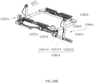
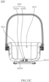
- FIG. 18A shows a perspective view of the locking base assembly 120A
- FIGS. 18B and 18C show the locking base assembly 120A with the base plate 1210A removed to show the supporting structure 1240A and the locking mechanism 1220A located in the base plate 1210A
- FIG. 18D shows a cross-sectional view of the locking base assembly 120A taken along the line X-X shown in FIG. 18A
- FIG. 18E shows a partial enlarged view of part J shown in FIG. 18D , in which the releasing operation element 1221A is in the locking position
- FIG. 18F shows a view in which the releasing operation element 1221A shown in FIG. 18E is in the unlocking position.
- the locking base assembly 120A includes a base plate 1210A, a locking mechanism 1220A (only the releasing operation element 1221A is shown in FIG. 18A , and the locking mechanism 1220Ais hidden by the base plate 1210A) and a supporting structure 1240A.
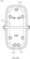
- the base plate 1210A may have a hollow structure (i.e. different from the base plate 1210 of the embodiment shown in FIG. 10B ).
- the base plate 1210A may have an annular structure (i.e., a middle area of the base plate 1210A is in a hollowed shape).
- the base plate 1210A may have a first extension part 1211A, for example, the first extension part 1211A may extend outward from one end (e.g., a middle part of the rear end) of the base plate 1210A by a certain distance to provide a larger supporting surface (i.e., a first abutting surface), so as to more stably support the carrier (not shown) disposed thereabove.
- a first extension part 1211A may extend outward from one end (e.g., a middle part of the rear end) of the base plate 1210A by a certain distance to provide a larger supporting surface (i.e., a first abutting surface), so as to more stably support the carrier (not shown) disposed thereabove.
- the base plate 1210A may also have a second extension part 1212A, which extends from the other end (e.g., the front end) of the base plate 1210Ato provide an additional supporting surface (i.e., a second abutting surface), thereby facilitating to improve the stability of the carrier on the carrying frame 110A and facilitating to keep balance after the carrier is engaged to the whole carrying frame 110A.
- a second abutting surface may be disposed at opposite ends of the base plate 1210A.
- the first extension part 1211A and/or the second extension part 1212A may also be provided as a handle to more conveniently move the carrying frame 110A in an unfolded state or a folded state.
- the supporting structure 1240A may include two supporting frames 1241A, which are respectively disposed on two sides of the base plate 1210A in the transverse, for example, symmetrically disposed on two sides of the base plate 1210A.
- the supporting frame 1241A of this embodiment is not provided with a shock absorbing structure.
- each supporting frame 1241A may include a longitudinal rod 12411A, a first sub-rod 12412A and a second sub-rod 12413A.
- the longitudinal rod 12411A is disposed below the base plate 1210A and fixedly connected with the base plate 1210A.
- first sub-rod 12412A and one end of the second sub-rod 12413A are respectively connected to the longitudinal rod 12411A, and the other end of the first sub-rod 12412A and the other end of the second sub-rod 12413A are connected to each other, so that the first sub-rod 12412A and the second sub-rod 12413A form a triangular structure with the longitudinal rod 12411A, so as to stably support the base plate 1210A and the object thereabove.
- the connection point between the second sub-rod 12413A and the longitudinal rod 12411A is located at a middle section of the base plate 1210A in its longitudinal direction D15.
- the supporting structure 1240A further includes a first connecting rod 1242A.
- the first connecting rod 1242A is a cross rod or a U-shaped rod that is symmetrically disposed. Specifically, the first connecting rod 1242A may be connected between the longitudinal rods 12411A on both sides.
- the first connecting rod 1242A is integrally formed with the longitudinal rods 12411A at both sides, that is, the first connecting rod 1242A and the longitudinal rods 12411A are the same rod.
- the locking base assembly 120A is pivotably connected and mounted on the carrying frame 110A through its supporting structure 1240A, in which the base plate 120A and the locking mechanism 1220A of the locking base assembly 120A are fixedly mounted on the supporting structure 1240A, and the base plate 120A provides a substantially horizontal supporting surface for placing an object (in this embodiment, the carrier).
- the supporting structure 1240A further includes a first connecting component 1244A and a second connecting component 1245A, which are pivotably connected to the carrying frame 110, respectively, so that the locking base assembly 120A may be folded together with the folding of the carrying frame 110A.
- one end of each of the first connecting component 1244A and the second connecting component 1245A is pivotally connected to one end of the first sub-rod 12412A (i.e., an end connected with the second sub-rod 12413A), and the other end of the first connecting component 1244A, the other end of the second connecting component 1245A and the other end of the first sub-rod 12412A are pivotably connected to the carrying frame 110A at different positions and are pivotable with respect to each other.
- the other end of the first connecting component 1244A is pivotably connected to the upper supporting rod 1130A of the carrying frame 110A
- the other end of the second connecting component 1245A is pivotably connected to the rear supporting rod 120A of the carrying frame 110A
- the other end of the first sub-rod 12412A is pivotably connected to the front supporting rod 110A of the carrying frame 110A, so that the supporting structure 1240A, together with the whole locking base assembly 120A, can pivot along with the pivoting of the frame 110A, thereby realizing the folding of the whole structure.
- the locking mechanism 1220A is mounted in the base plate 1210A for locking and unlocking the object located on the base plate 1210A.
- the locking mechanism 1220A includes at least one releasing operation element 1221A and at least one locking element 1222A.
- the releasing operation element 1221A is disposed in the base plate 1210A and is movable between a locking position and an unlocking position with respect to the base plate 1210A.
- the difference between the releasing operation element 1221A and the releasing operation element 1221 of the previous embodiment is that, as shown in FIGS.
- the releasing operation element 1221A is slidably connected to the locking element 1222A, so that the locking element 1222A may move correspondingly with the movement of the releasing operation element 1221A.
- the releasing operation element 1221A is in the locking position as shown in FIG. 18D , at least a part of the releasing operation element 1221A protrudes from the base plate 1210A, so that the object placed on the base plate 1210A is locked; while when the releasing operation element 1221A is pressed to move from the locking position to the unlocking position, the locking element 1222A moves with the movement of the releasing operation element 1221A, thereby releasing the object located on the base plate 1210A.
- the locking element 1222A may move in the substantially horizontal direction to realize the unlocking. That is, a moving direction of the releasing operation element 1221A and a moving direction of the locking element 1222Amay be substantially perpendicular to each other.
- the at least one locking element 1222A may be a plurality of locking elements 1222A, and the connection relationship between the locking elements 1222A (e.g., linkage assembly, linkage, etc.) is similar to the previous embodiment, which will not be described in detail herein.
- the specific structure of the locking element 1222A and its specific linkage mode with the releasing operation element 1221A, especially the difference from the locking element 1222 in the previous embodiment, will be described in detail below.
- the locking element 1222A is provided with a locking part 1222Aa, and an opening is provided on the base plate 1210A at a position corresponding to the locking part 1222Aa, so that the locking part 1222Aa may extend from the opening of the base plate 1210A to lock an object placed on the base plate 1210A.
- the base plate 1210A may be correspondingly provided with a recess, an inclined surface, etc., which will not be described in detail herein.
- the locking element 1222A may have a first portion 12221A and a second portion 12222A that are fixedly connected to each other.
- the second portion 12222A is connected below the first portion 12221A and extends from one end of the first portion 12221Ato the releasing operation element 1221A.
- the end of the first portion 12221A is spaced apart from the releasing operation element 1221A by a certain distance.
- the locking part 1222Aa is provided at the end of the first portion 12221A (i.e., one end close to the releasing operation element 1221A), while one end of the second portion 12222A extending close to the releasing operation element 1221Ais slidably connected with the releasing operation element 1221A.
- the first portion 12221A and the second portion 12222A may be separate parts and fixedly connected together by bolts or the like.
- the first portion 12221A and the second portion 12222A may be integrally formed.
- a driving pin 12211A may also be fixedly disposed on the releasing operation element 1221A.
- An inclined hole 1222Ab is disposed at one end of the second part 1222a of the locking element 1222a close to the releasing operation element 1221A, and the driving pin 12211A of the releasing operation element 1221A may slide in the inclined hole 1222Ab, that is, the driving pin 12211A may slide with respect to the inclined hole 1222Ab with the operation of the releasing operation element 1221A.
- the inclined hole 1222Ab may be provided to be inclined downward from the inside to the outside.
- FIG. 18E shows a state in which the releasing operation element 1221A is in the locking position
- FIG. 18F shows a state in which the releasing operation element 1221A is in the unlocking position.
- the driving pin 12211A may slide with respect to the inclined hole 1222Ab with the movement of the releasing operation element 1221A, so as to drive the locking element 1222A to move from the locking position to the unlocking position.
- the releasing operation element 1221A may be pressed down by the user, and the releasing operation element 1221A moves from the locking position (see FIG.
- the locking mechanism 1220 of this embodiment may also be provided with an elastic device 1224A to provide a force for enabling the releasing operation element 1221A to be in or restored to the locking position.
- an elastic device 1224A may be disposed between two locking elements 1222A on the same side, tending to keep the two locking elements 1222A away from each other. Referring to FIGS. 18D to 18F , when the releasing operation element 1221A is released, the locking element 1222A may move to its locking position under the action of the elastic device 1224A, while the releasing operation element 1221A moves upward to its locking position under the force of the inclined hole 1222a with respect to the driving pin 12211A.
- a second aspect of the present disclosure also provides a wheeled carrying apparatus 21.
- FIG. 19A shows a perspective schematic view of the wheeled carrying apparatus 21 according to the second aspect of the present disclosure.
- the wheeled carrying apparatus 21 may include a carrying frame 2100, a locking base assembly 2200 and a carrier 2300.
- the locking base assembly 2200 may be mounted on the carrying frame 2100, and the carrier 2300 may be fixed on the carrying frame 2100 through the locking base assembly 2200 so as to move together with the carrying frame 2100.
- the carrier 2300 may include a main body 2310 and a bracket device 2320, wherein the main body 2310 (which may also act as a "carrying portion") provides an accommodation space (i.e., a carrying space) for carrying (i.e., loading) pets.
- the bracket device 2320 is mounted on the main body 2310 to support the main body 2310, and may be engaged with the locking base assembly 2200, so that the carrier 2300 is detachably mounted on the carrying frame 2100 through the bracket device 2320.
- FIG. 19B shows a perspective view of a carrying frame 2100 according to the second aspect of the present disclosure
- FIG. 19C shows a perspective view of the carrying frame 2100 shown in FIG. 19B from another view.
- the carrying frame 2100 of the present disclosure may include a front supporting rod 2110, a rear supporting rod 2120 and an upper supporting rod 2130.
- the front supporting rod 2110 is connected with a front wheel 2181
- the rear supporting rod 2120 is connected with a rear wheel 2182
- the upper supporting rod 2130 is connected with a handrail 2170.
- one end of the front supporting rod 2110, one end of the rear supporting rod 2120 and one end of the upper supporting rod 2130 are pivotally connected to each other at a first pivoting part A2, so that the front supporting rod 2110, the rear supporting rod 2120 and the upper supporting rod 2130 may be folded with respect to each other through the first pivoting part A2.
- the front supporting rod 2110 may have a U-shaped structure
- the rear supporting rod 2120 may be formed by two parallel rod elements fixedly connected through a cross rod, and both ends of the front supporting rod 2110 are pivotally connected to one ends of the two rod elements of the rear supporting rod 2120 at the first pivoting part A2.
- At least one front wheel 2181 is connected to a lower side of the front supporting rod 2110, and the other ends of the two rod elements of the rear supporting rod 2120 are respectively connected to the corresponding rear wheels 2182.
- the handrail 2170 is located at the other end (i.e., an upper end) of the upper supporting rod 2130, and is pivotably connected with the upper supporting rod 2130 through a second pivoting part B2.
- the present disclosure is not limited to the above structure, and the front supporting rod 2110 may also have a V-shaped or I-shaped structure, and the rear supporting rod 2120 may also be provided in an integrally formed U-shaped structure.
- a size of the rear wheel 2182 may be larger than that of the front wheel 2181 to make the overall structure of the wheeled carrying apparatus 21 more stable.
- the carrying frame 2100 is also provided with a connecting assembly (which will be described in detail below) for mounting the locking base assembly 2200 on the carrying frame 2100, and the connecting assembly is pivotably connected to the carrying frame 2100, so that the locking base assembly 2200 may pivot through the connecting assembly with the folding of the carrying frame 2100.
- the connecting assembly may also serve as a supporting structure for the locking base assembly 2200, for example, act as "supporting structure 1240" and/or "supporting structure 1240A" as described in the first aspect of the present disclosure.
- the connecting assembly may include a first coupling element 2140, an auxiliary support 2150 and a linking element 2160.
- one end of the first coupling element 2140 is pivotably connected to the front supporting rod 2110 at a first pivot point 021.
- the auxiliary support 2150 is pivotably connected to the other end of the first coupling element 2140 at a second pivot point O22, and is pivotably connected to the rear supporting rod 2120 at a third pivot point O23.
- One end of the linking element 2160 is pivotably connected to the upper supporting rod 2130 at a fourth pivot point O24, and the other end of the linking element 2160 is pivotably connected to the auxiliary support 2150 at a fifth pivot point O25.
- the fifth pivot point O25 is between the second pivot point O22 and the third pivot point O23, that is, the second pivot point O22 is between the first pivot point 021 and the fifth pivot point O25.
- the fifth pivot point O25 may coincide with the second pivot point O22.
- the linking element 2160 may have an approximately S-shaped structure, so as to avoid interference with the rear supporting rod 2120, the base plate 2200 or other components when the carrying frame 2100 is folded, that is, to form an avoidance structure.
- the approximately S-shaped structure has a first section 2161, a second section 2162 and a third section 2163 sequentially.
- the second section 2162 is substantially perpendicular to the first section 2161
- the third section 2163 is substantially perpendicular to the second section 2162.
- the first section 2161 substantially overlaps with the upper supporting rod 2130.
- linking element 2160 may also be designed into other shapes or structures that can avoid other components when being folded.
- the linking element 2160 may also be provided in the form of a straight bar by adjusting other components so that a plurality of rod elements or components may not interfere with each other during folding.
- first coupling elements 2140 may be provided. One ends of the two first coupling elements 2140 are respectively connected to the front supporting rods 2110 on both sides, and the auxiliary support 2150 may have a generally U-shaped structure, and both ends of the auxiliary support 2150 are respectively connected to the other ends of the corresponding first coupling elements 2140.
- the auxiliary support 2150 may also be provided with two separate linear rod elements, each of which is connected between the first coupling element 2140 and the rear supporting rod 2120 at one side of the carrying frame 2100, but the present disclosure is not limited thereto.
- the first coupling element 2140 and the auxiliary support 2150 are horizontally disposed, and the first pivot point 021, the second pivot point O22, the third pivot point O23 and the fifth pivot point O25 are on the same horizontal plane, and optionally, these pivot points are substantially in a straight line.
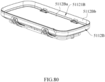
- FIG. 20 shows a schematic perspective view of the locking base assembly 2200 according to the present disclosure
- FIG. 21 shows a schematic perspective view of the locking base assembly 2200 shown in FIG. 20 after the base plate 2210 is removed.
- the first bracket 3121 may also be an annular structural element.
- the first bracket 3121 surrounds and defines a first plane
- the engaging element 31231 surrounds and defines a second plane.
- An area of the second plane may not be larger than that of the first plane, and is approximately close to that of the bottom portion 3111 of the main body 3110.
- the first plane and the second plane correspond to the same central axis L (i.e., the central axis L passes through centers of the first plane and the second plane), and the second structural reinforcement element 31234 may be disposed in a way of passing through or approaching the central axis.
- the main body 3110 also includes an accommodation structure 3114, which may be a concave structure, and includes an annular groove 31141 and a U-shaped groove 31142 for partially accommodating the first bracket 3121 and the second bracket 3122, respectively, so as to firmly combine the main body 3110 with the bracket device 3120.
- the first bracket and the second bracket may be completely accommodated in the accommodation structure and substantially flush with a surface of the main body.
- the accommodation structure may be omitted.
- the accommodation structure may only include an annular groove for partially accommodating the first bracket or a U-shaped groove for partially accommodating the second bracket.
- the four guides 31242A, 31242B, 31242C and 31242D may be disposed in the second plane surrounded by the engaging element 31231, and are respectively located at the corresponding four first connecting brackets 31241.
- the third bracket 3123 may be guided to cooperate with the engaging structure 3B1 through two guides 31242A and 31242B located in the engaging area on one side of the engaging element 31231 or other two guides 31242C and 31242D located in the engaging area on the other side of the engaging element 31231, so that the base 3B0 may be positioned at different positions with respect to the carrier 3100, for example, the base 3B0 may be positioned on two opposite sides of the bottom portion 3111 of the carrier 3100 in the longitudinal direction D31.
- the guide 31242 may be a sheet-like structural element made of plastic, metal or other materials with certain rigidity, but the present disclosure is not limited to this embodiment.
- FIG. 32G is a top view of the carrier 3100 according to the first embodiment of the third aspect of the present disclosure
- FIG. 32H is a partial structural cross-sectional view of the carrier 3100 according to the first embodiment of the third aspect of the present disclosure
- FIG. 32I is another partial structural cross-sectional view of the carrier 3100 according to the first embodiment of the third aspect of the present disclosure.
- the fixing assembly 3124 further includes a plurality of bracket connecting elements 31243 (shown in FIG. 32G ), a plurality of securing combinations 31244 (shown in FIGS.
- the plurality of second connecting brackets 31245 may be mounted on two opposite sides of the engaging element 31231 in the longitudinal direction D31, so that the main body 3110 and the bracket device 3120 can be combined more stably, wherein a length of the second connecting bracket 31245 needs to be larger than that of the first connecting bracket 31241 since there is no corresponding second bracket 3122 above the second connecting bracket 31245.
- the two second connecting brackets 31245 on one side of the engaging element 31231 may be spaced apart from each other, which not only enables the engaging element 31231 to be more evenly stressed on this side, but also allows another element (such as an adjuster 3140) to be disposed between the two second connecting brackets 31245, thereby making the structure more compact.
- the bracket connecting element 31243 located at the corresponding first connecting bracket 31241 may at least partially be located within the through slot 31111 and abut against the transverse part 31222 of the second bracket 3122, and the securing element 312442 located at the corresponding first connecting bracket 31241 may pass through the corresponding guide (such as the guide 31242C), the first structural reinforcement element 31233 of the third bracket 3123, the corresponding first connecting bracket 31241 and the transverse part 31222 of the corresponding second bracket 3122 and the corresponding bracket connecting element 31243 and be locked with the corresponding matching element 312441.
- the corresponding guide such as the guide 31242C
- the bracket connecting element 31243 located at the corresponding second connecting bracket 31245 may be at least partially located within and abut against the corresponding second connecting bracket 31245, and the securing element 312442 located at the corresponding second connecting bracket 31245 may pass through the engaging element 31231 of the third bracket 3123, the corresponding second connecting bracket 31245 and the corresponding bracket connecting element 31243 and be locked with the corresponding matching element 312441.
- the securing combination may be omitted, and the bracket connecting element may be connected to the second bracket or the second connecting bracket through the cooperation of an engaging protrusion and an engaging notch.
- the number and arrangement position of the groove in the present disclosure are not limited to this embodiment.
- the bottom of the main body is provided with one groove, which is centrally disposed.
- the groove and the recess may be omitted.
- each of the limiting sections 3131 may pass through the corresponding bottom opening 31113 via the corresponding first bracket opening 31252 or the corresponding second bracket opening 31262.
- the adjuster 3140 is disposed on the third bracket 3123, the adjustment section 3132 of the binding webbing 3130 passes through the adjuster 3140, and the adjuster 3140 is configured to adjust and lock the binding webbing 3130.
- Each of the protruding structures 31253 is at least partially inserted in the corresponding bottom opening 31113 to avoid the binding webbing 3130 from rubbing against the main body 3110 during adjustment and to increase the structural strength of the corresponding bottom opening 31113.
- FIG. 32L is a schematic view of the carrier 3100 according to the first embodiment of the third aspect of the present disclosure when the grip 3150 is in a folded state.
- the carrier 3100 further includes a grip 3150, which is pivotally connected to the first bracket 3121.
- the grip 3150 By pivoting the grip 3150, the carrier may be switched between a usage state as shown in FIG. 32A and a folded state as shown in FIG. 32L , thereby achieving the purpose of convenient carrying and storage.
- the grip 3150 is substantially centrally disposed on the main body 3110 at upper edges of two sidewalls thereof, so that the grip 3150 can be smoothly folded to two sides of the main body 3110.
- FIG. 33C is a schematic cross-sectional view of the carrier 3200 according to the second embodiment of the third aspect of the present disclosure
- FIG. 33D is a top view of the carrier 3200 according to the second embodiment of the third aspect of the present disclosure when the grip is in the folded state
- FIG. 33E is an enlarged partial structural schematic view of the carrier 3200 according to the second embodiment of the third aspect of the present disclosure.
- the bracket connecting elements 32243, the securing combinations 32244 and the through slots (not shown) located at both sides of the main body 3210 may be disposed corresponding to the two second connecting brackets 32245.
- FIGS. 33C is a schematic cross-sectional view of the carrier 3200 according to the second embodiment of the third aspect of the present disclosure
- FIG. 33D is a top view of the carrier 3200 according to the second embodiment of the third aspect of the present disclosure when the grip is in the folded state
- FIG. 33E is an enlarged partial structural schematic view of the carrier 3200 according to the second embodiment of the third aspect of the
- the bottom portion 3211 of the main body 3210 is only provided with one bottom opening 32113, which is located at an approximately center position of the main body 3210.
- a distance between the second structural reinforcement element 32234 and the first structural reinforcement element 32232 is slightly larger than a distance between the second structural reinforcement element 31234 and the first structural reinforcement element 32233 so as to be adapted to the arrangement position of the bottom opening 32113.
- a central part of the second structural reinforcement element 32234 located between the two first structural reinforcement elements 32232 and 32233 is bent towards the bottom portion 3211 of the main body 3210 and configured to abut against the bottom portion 3211 of the main body 3210, so as to enhance the impact resistance of the bracket device 3220.
- the bracket device 3220 only includes one positioning bracket 3225, which is connected to the central part of the second structural reinforcement element 32234 and located at the approximately center portion of the corresponding main body 3210.
- the positioning bracket 3225 includes a bracket body 32251, one bracket opening 32252 formed on the bracket body 32251 and located at the corresponding bottom opening 32113, and one protruding structure 32253 protruding from the bracket body 32251 and at least partially inserted in the bottom opening 32113.
- the binding webbing 3230 only includes one limiting section 3231, but does not include an adjustment section.
- the carrier 3200 does not include an adjuster.
- the limiting section 3231 is provided with a clamping element 3233, which may be buckled with a buckle ring on a pet vest, thereby limiting the pet in the accommodation space 3213.
- Other structures of this embodiment are similar to those of the first embodiment and also have similar diverse changes as those of the first embodiment, which will not be repeated herein for the sake of brevity.
- FIGS. 34A to 34C are schematic appearance views of the carrier 3300 according to a third embodiment of the third aspect of the present disclosure from different views.
- the carrier 3300 does not include a binding webbing and an adjuster
- the bottom portion 3311 of the main body 3310 is not provided with a bottom opening
- the bracket device 3320 does not include a positioning bracket
- the second structural reinforcement element 33234 is at approximately equal distances from each of the two first structural reinforcement elements 33232 and 33233.
- Other structures of this embodiment are similar to those of the second embodiment, and also have similar diverse changes as those of the second embodiment, which will not be repeated herein for the sake of brevity.
- the present disclosure also provides a carrier having a detachable canopy.
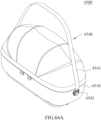
- FIGS. 35A and 35B are schematic appearance views of the carrier 3400 according to a fourth embodiment of the third aspect of the present disclosure in different states
- FIG. 35C is a partial structural view of the carrier 3400 of the fourth embodiment of the third aspect of the present disclosure after a canopy 3460 and a cloth 3480 are removed.
- the carrier 3400 includes a canopy 3460, a canopy connecting assembly 3470 and a cloth 3480 that at least partially covers the main body 3410 and the bracket device 3420.
- the grip 3450 is exposed to the cloth 3480 so as to facilitate to be held by the user, while the third bracket 3423 is also exposed to the cloth 3480 to facilitate the cooperation with the base.
- the canopy connecting assembly 3470 is disposed between the canopy 3460 and the cloth 3480 for detachably connecting the canopy 3460 and the cloth 3480 with each other.
- the canopy 3460 includes a first cover 3461, a second cover 3462 and a cover connecting assembly 3463.
- the cover connecting assembly 3463 is disposed between the first cover 3461 and the second cover 3462 for detachably connecting the first cover 3461 and the second cover 3462 with each other.
- the canopy connecting assembly 3470 and the cover connecting assembly 3463 may be zipper assemblies.
- the canopy connecting assembly may be disposed between the canopy and the main body
- the canopy connecting assembly may include a male buckle and a female buckle or two hook-and-loop fasteners (which may also referred to as "Velcro” or “Velcro tape”) respectively disposed on the canopy and the main body
- the cover connecting assembly may include a male buckle and a female buckle or two hook-and-loop fasteners respectively disposed on the first cover and the second cover.
- Other structures of this embodiment are similar to those of the third embodiment, and also have similar diverse changes as those of the second embodiment, which will not be repeated herein for the sake of brevity.
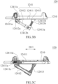
- FIG. 36A is a schematic appearance view of a carrier 3500 according to the fifth embodiment of the third aspect of the present disclosure
- FIG. 36B is a partial structural schematic view of the carrier 3500 according to the fifth embodiment of the third aspect of the present disclosure after a canopy and a cloth are removed.
- the carrier 3500 includes a strap 3590 for the user to wear and two first strap connecting elements 35A0, but does not include a grip.
- the two first strap connecting elements 35A0 are disposed on the first bracket 3521.
- the strap 3590 includes a strap body 3591 and two second strap connecting elements 3592 disposed on the strap body 3591 for detachably connecting the first strap connecting elements 35A0 respectively.
- the two first strap connecting elements 35A0 may be two engaging rings which are disposed at two opposite short sides of the first bracket 3521 and exposed from the cloth 3580 respectively
- the two second strap connecting elements 3592 may be two engaging hooks which are disposed at two ends of the strap body 3591 respectively.
- an outer side of a short side of a peripheral wall of the main body 3510 may be formed with a first positioning slot 3515 for accommodating and positioning the first strap connecting element 35A0 to prevent the first strap connecting element 35A0 from moving arbitrarily.
- the short side of the first bracket may also be provided with a positioning protrusion for positioning the first strap connecting element and preventing the first strap connecting element from moving excessively.
- the first strap connecting element and the second strap connecting element may be omitted, and the strap may be connected to the first bracket in a winding manner.
- Other structures of this embodiment are similar to those of the fourth embodiment, and also have similar diverse changes as those of the second embodiment, which will not be repeated herein for the sake of brevity.
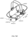
- FIG. 37A is schematic appearance view of a carrier 3600 according to a sixth embodiment of the third aspect of the present disclosure
- FIG. 37B is a partial structural schematic view of the carrier 3600 according to the sixth embodiment of the third aspect of the present disclosure after a canopy and a cloth are removed.
- the carrier 3600 includes a fixing rope 36B0 for cooperating with a vehicle seat and two first fixing rope connectors 36C0, but does not include a strap.
- the two first fixing rope connectors 36C0 are disposed on the first bracket 3621.
- the fixing rope 36B0 includes a rope body 36B1 and two second fixing rope connectors 36B2 disposed on the rope body 36B 1.
- the cooperation between the fixing rope 36B0 and the vehicle seat is realized by winding the rope body 36B1 around a headrest supporting rod of the vehicle seat, and the two second fixing rope connectors 36B2 are used for detachably connecting the two first fixing rope connectors 36C0 respectively.
- the two first fixing rope connectors 36C0 may be two engaging rings which are respectively disposed at a long side of the first bracket 3621 and exposed from the cloth 3680
- the two second fixing rope connectors 36B2 may be two engaging hooks respectively disposed at both ends of the rope body 36B 1.
- the two first fixing rope connectors 36C0 may be located adj acent to one ends of the vertical parts 36221 of the two second brackets 3622, respectively. Compared with other arrangement positions on the first bracket 3621, the first bracket 3621 may not be deformed when bearing the tensile force of the rope body 36B1, so that the carrier 3600 has higher impact resistance.
- an outer side of a long side of a peripheral wall of the main body 3610 is formed with a second positioning slot 3616 for accommodating and positioning the first fixing rope connector 36C0, so as to prevent the first fixing rope connector 36C0 from moving excessively.
- a long side of the first bracket may also be provided with a positioning protrusion for positioning the first fixing rope connector and preventing the first fixing rope connector from moving excessively.
- the first fixing rope connector and the second fixing rope connector may be omitted, and the fixing rope may be connected to the first bracket in a winding way.
- the carrier 3600 may also include a first positioning slot and two first strap connecting elements to cooperate with the strap, thus having various application modes.
- Other structures of this embodiment are similar to those of the fifth embodiment, and also have similar diverse changes as those of the second embodiment, which will not be repeated herein for the sake of brevity.
- FIG. 38A is a schematic appearance view of a carrier 3700 according to a seventh embodiment of the third aspect of the present disclosure.
- the rope body 37B1 of the fixing rope 37B0 is Y-shaped, and the cooperation between the fixing rope 37B0 and the vehicle seat is realized by fastening the engaging hook 37B3 disposed at an end of the rope body 37B1 away from the first bracket onto a headrest supporting rod or a backrest engaging rod of the vehicle seat.
- the first bracket is combined to the main body and disposed around the peripheral wall of the main body
- the second bracket is combined to the main body and extends from one side of the peripheral wall of the main body to the other side of the peripheral wall of the main body through the bottom portion of the main body.
- the main body of any of the above-mentioned embodiments according to the third aspect of the present disclosure may also be mounted on the wheeled carrying apparatus described in any of the first and second aspects of the present disclosure, for example, through the third bracket of the respective bracket device, and the specific mounting method may refer to the first aspect and will not be described herein.
- a fourth aspect of the present disclosure also provides other embodiments of carriers, for example, a detachable canopy assembly and a carrier including the same may be provided.
- the carriers in the fourth aspect of the present disclosure are denoted by "4100" to "4800", respectively.
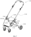
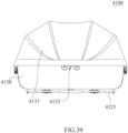
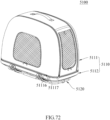
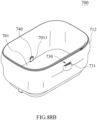
- FIGS. 39 and 40 respectively show a carrier 4100 according to an embodiment of the fourth aspect of the present disclosure in different states.
- FIG. 39 shows a schematic front view of the carrier 4100
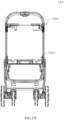
- FIG. 40 shows a structural schematic view of the carrier 4100 shown in FIG. 39 after a canopy and a cloth are removed.
- the carrier 4100 may include a main body 4110, a bracket device 4120 and a canopy assembly 4130.
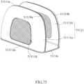
- the canopy assembly includes a canopy frame 4131, a canopy locking device 4132 and a canopy 4133, which will be described in detail below.
- a cloth 4150 is at least partially sleeved around the carrier 4100 shown in FIG. 39 , and the cloth 4150 at least partially covers the main body 4110, the bracket device 4120 and the canopy assembly 4130.
- FIG. 40 is a perspective structural schematic view of the carrier 4100 after a canopy 4133 and the cloth 4150 shown in FIG. 39 are removed.
- the main body 4110 (which may also be referred to as "carrying portion”) includes a bottom portion 4111 and a peripheral wall 4112 connected around the bottom portion 4111, and the bottom portion 4111 and the peripheral wall 4112 form an accommodation space 4113 (i.e., a carrying space).
- the accommodation space 4113 has an opening that is opened upward for children or pets to ride in the accommodation space.
- the bracket device 4120 is at least partially disposed around the main body 4110, for example, sleeved outside the main body 4110 from below the main body 4110, for supporting the main body 4110.
- the bracket device 4120 includes a first bracket 4121, a second bracket 4122 and a third bracket 4123.
- the first bracket 4121 is disposed substantially horizontally, surrounding the peripheral wall 4112 of the main body 4110 and being close to the opening of the main body 4110.
- Two ends of the second bracket 4122 are respectively connected to the first bracket 4121, and extend from one side of the peripheral wall 4112 of the main body 4110 to the other side of the peripheral wall 4112 of the main body 4110 along a transverse direction D42 of the main body 4110 via the bottom portion 4111 of the main body 4110.
- two or more second brackets 4122 may be provided, and these second brackets 4122 are respectively connected to the first bracket 4121 and disposed in parallel with each other at intervals along a longitudinal direction D41.
- the third bracket 4123 is disposed substantially horizontally and connected with the second bracket 4122, and is located at a bottom side of the bottom portion 4111 of the main body 4110 with a certain distance therebetween.
- the carrier 4100 may be supported and fixed on a trolley or a vehicle seat, for example.
- the canopy locking device 4132 is disposed on the canopy frame 4131 to detachably cooperate with the canopy locking part 4124 correspondingly disposed on the carrier 4100, so that the canopy assembly 4130 may be locked above the main body 4110. Specifically, when the canopy assembly 4130 is mounted around the main body 4110, the canopy locking device 4132 may cooperate with the corresponding canopy locking part 4124 on the first bracket 4131 of the bracket device 4130, so that the canopy frame 4131 of the canopy assembly 4130 may be detachably connected to the bracket device 4120 of the carrier 4100 (i.e., detachably mounted above the main body 4110).
- two canopy locking devices 4132 may be disposed symmetrically on the canopy frame 4131 at both sides of the main body 4110 in the transverse direction D42.
- the canopy locking device 4132 may be centrally disposed on the canopy frame 4131 at a side thereof along the longitudinal direction D41, that is, a centerline of the canopy locking device 4132 coincides with a centerline M41 of an edge of the canopy frame 4131 at a side thereof.
- the canopy frame and the canopy locking device may also be uniformly referred to as a "canopy connecting assembly".
- FIGS. 41 to 43 a process of disassembling the canopy assembly 4130 from the main body 4110 according to an embodiment of the fourth aspect of the present disclosure is schematically shown.
- the canopy and the cloth are omitted from FIGS. 41 to 43 to make the structure clearer.
- FIG. 41 shows the carrier shown in FIG. 40 from another view, in which the canopy assembly 4130 is mounted to the main body 4110;
- FIG. 42 shows a state in which the canopy assembly 4130 is being removed from the main body 4110;
- FIG. 43 shows a state in which the canopy assembly 4130 has been removed.
- the canopy frame 4131 when it is necessary to use the canopy, the canopy frame 4131 is connected to the first bracket 4121 through the cooperation of the canopy locking device 4132 of the canopy assembly 4130 and the canopy locking part 4124, and the canopy frame 4131 is substantially parallelly disposed above the first bracket 412. At this time, the canopy frame 4131 is sleeved outside the main body 4110, so that the canopy disposed on the canopy frame 4131 (not shown in FIG. 41 , referring to FIG. 39 ) can cover the entire opening of the main body 4110. As shown in FIGS.
- the canopy locking device 4132 when the canopy is not needed, the canopy locking device 4132 may be separated from the canopy locking part 4124 disposed on the first bracket 4121, so that the canopy assembly 4130 (including the canopy provided thereon) may be separated from the main body 4110, while the canopy assembly 4130 may be stored by the user.
- the specific cooperating mode of the canopy locking device 4132 and the canopy locking part 4124 will be described below.
- the canopy frame 4131 and the canopy locking device 4132 provided thereon according to an embodiment of the fourth aspect of the present disclosure are shown.
- the canopy locking device 4132 includes a releasing operation element 41321.
- the releasing operation element 41321 is disposed on the canopy frame 4131 and is capable of being operated to move from a locking position to an unlocking position, so as to unlock the canopy assembly 4130 with respect to the main body 4110.
- the canopy locking device 4132 also includes a locking element 41322.
- the locking element 41322 is mounted on the canopy frame 4131, and the releasing operation element 41321 is disposed on the canopy frame 4131 and operatively acts on the locking element 41322. As shown in FIG.
- the locking element 41322 may be at least partially disposed in a housing of the canopy frame 4131, and the rest portion of the locking element 41322 extends downward out of the housing, so as to cooperate with the aforementioned canopy locking part.
- the releasing operation element 41321 may be at least partially disposed in the housing of the canopy frame 4131, and the rest portion thereof may extend downward out of the housing for the user to contact and operate, so as to unlock the locking element 41322.
- FIGS. 45 and 46 respectively show the canopy locking device 4132 in which the releasing operation element 41321 is in the locking position and the unlocking position
- FIGS. 47 and 48 respectively show locking and unlocking of the releasing operation element 41321 with respect to the canopy locking part 4124.
- FIG. 45 shows a structural schematic view of the canopy locking device 4132 at a part A in FIG. 44 , in which a part of the housing at the part A shown in FIG. 44 is removed to show the specific structure of the canopy locking device 4132 in a locked state; and FIG. 46 shows the specific structure of the canopy locking device 4132 shown in FIG. 45 in an unlocked state.
- the locking element 41322 is pivotably mounted to the canopy frame 4131, and the locking operation element 41321 is connected to the locking element 41322 and is movable between the locking position ( FIG. 45 ) and the unlocking position ( FIG. 46 ).
- the locking element 41322 may be pivotally connected to the canopy frame 4131 around a pivot point 041 and pivotally connected to the releasing operation element 41321 around another pivot point O42 that is different from the pivot point 041.
- the releasing operation element 41321 may move between the locking position and the unlocking position with respect to the canopy frame 4131 in a vertical direction, and drives the locking element 41322 to be pivoted with respect to the canopy frame 41321 around the pivot point 041.
- two locking elements 41322 may be provided.
- the two locking elements 41322 are disposed in mirror symmetry in the canopy locking device 4132 and are respectively pivotally connected to both sides of the same releasing operation element 41321.
- the two locking elements 41322 are respectively pivotally connected to the canopy frame 4131 at two pivot points 041 symmetrically provided along the centerline M41, and are respectively pivotally connected to the pivot points 042 with two ends of the releasing operation element 41321.
- the canopy locking device 4132 may further include an elastic restoring element 41323.
- the elastic restoring element 41323 is connected between the releasing operation element 41321 and the canopy frame 4131, and constantly provides a force to enable the releasing operation element 41321 to be in or restored to the locking position. That is, as shown in FIG. 45 , the elastic restoring element 41323 constantly exerts a vertical downward force on the releasing operation element 41321, so that the releasing operation element 41321 always tends to protrude from the housing of the canopy frame 4131.
- FIG. 47 shows a schematic view of the canopy locking device 4132 that is locked with the canopy locking part 4124
- FIG. 48 shows a schematic view of the canopy locking device 4132 that is unlocked with the canopy locking part 4124.
- the locking element 41322 is pivotably mounted to the canopy frame 4131, and is engaged with or disengaged from the canopy locking part 4124 by moving with respect to the canopy frame 4131, thereby locking or unlocking the canopy frame 4131 to a main body (not shown). Specifically, when the releasing operation element 41321 is in the locking position (see FIG. 47 ), the locking element 41322 is engaged with the canopy locking part 4124; and when the releasing operation element 41321 is operated to the unlocking position (see FIG. 48 ), the locking element 41322 is disengaged from the canopy locking part 4124.
- the locking element 41322 has an engaging hook protruding towards the canopy locking part 4124, and the canopy locking part 4124 includes an engaging pin 41241 disposed corresponding to the engaging hook.
- the engaging hook is engaged with the engaging pin 41241.
- the releasing operation element 41321 is operated to push the locking element 41322 to be pivoted to be in the unlocking position, the engaging hook is disengaged from the engaging pin 41241. More specifically, further in combination with FIGS.
- the user may operate (for example, press) the releasing operation element 41321, and the locking element 41322 pivoted with the releasing operation element 41321 is driven to be pivoted from the locking position to the unlocking position through the movement of the releasing operation element 41321 in the vertical direction, so that the engaging hook of the locking element 41322 is disengaged from the engaging pin 41241 of the canopy locking part 4124 provided on the first bracket 4121, so as to realize the unlocking and enable the canopy assembly 4130 to be removed.
- the canopy frame 4131 is also provided with a locking guide 41316.
- the locking guide 41316 is disposed on a side of the locking element 41322, and may guide the positioning of the canopy locking device 4132 with respect to the canopy locking part 4124 to assist the locking of the locking element 41322 and the canopy locking part 4124.
- the canopy assembly 4130 is mounted to the first bracket 4121 (not shown in FIG. 47 , see FIG.
- the locking guide 41316 may be disposed to abut against an inner edge of the canopy locking part 4124, so as to guide the canopy locking device 4132 and enable the canopy locking device 4132 to be disposed corresponding to the canopy locking part 4124, thereby locking and releasing the engaging hook of the locking part 41322 with the engaging pin 41241 of the corresponding canopy locking part 4124.
- FIGS. 49 and 50 different states of the canopy frame 4131 according to an embodiment of the fourth aspect of the present disclosure are shown.
- FIG. 49 shows the canopy frame 4131 in the unfolded state
- FIG. 50 shows the canopy frame 4131 in the folded state.
- the canopy frame 4131 has a triple-section folding structure. As shown in FIGS. 49 and 50 , the canopy frame 4131 may include a first pivoting section 41311, a second pivoting section 41312 and two locking sections 41315. Two ends of the first pivoting section 41311 are respectively pivotably connected to one ends of two locking sections 41315 through a first pivoting part 41313, and two ends of the second pivoting section 41312 are respectively pivotally connected to the other ends of the two locking sections 41315 through a second pivoting part 41314. Each of the two locking sections 41315 is provided with a canopy locking device 4132. In an example, a size of the locking section 41315 provided with the canopy locking device 4132 according to the present disclosure may be between 160 mm and 180 mm, optionally 173 mm.
- FIG. 51A shows a cross-sectional perspective view of the first pivoting part 41313 taken along a line K-K shown in FIG. 49
- FIG. 51B shows a structure of the first pivoting part 41313 at a side of the locking section 41315
- FIG. 51C shows a structure of the first pivoting part 41313 at a side the first pivoting section 41311.
- the first pivoting part 41313 is provided with a section position adjusting structure, such as gear teeth, so that the first pivoting section 41311 may be kept at different angles with respect to the locking section 41315.
- the first pivoting part 41313 is formed by the mutual pivotal connection of the first pivoting section 41311 and the locking section 41315.
- an end of the locking section 41315 is provided with first gear teeth 41313a
- an end of the first pivoting section 41311 is provided with second gear teeth 41313b.
- the second pivoting part 41314 may also be provided with the same structure as the first pivoting part 41313, that is, provided with gear teeth, so that the second pivoting section 41312 may be kept at different angles with respect to the locking section 41315.
- the present disclosure is not limited thereto, and the canopy frame 4131 may also be provided with other section position adjusting structures, so that the pivoting section of the canopy frame 4131 is at different angles with respect to the opening of the main body.
- the first pivoting part 41313 is also provided with a return spring 41313c to constantly bias the first pivoting part 41313 towards a direction of unfolding the canopy frame 4131, so as to provide assistance in the process of unfolding the canopy frame.
- the second pivoting part 41314 may also be provided with a return spring to assist in unfolding the canopy frame.
- FIGS. 52 to 54B respectively show the main body 4110 mounted with the canopy frame 4131 in different states.
- the canopy frame 4131 in FIG. 52 and the canopy 4133 in FIG. 54A are in the unfolded state, and the canopy frame 4131 in FIG. 53 and the canopy 4133 in FIG. 54B are in the folded state.
- the canopy locking device 4132 disposed in the locking section 41315 may be locked with the canopy locking part 4124 disposed on the first bracket 4121, so that at least a part of the canopy frame 4131 (i.e., the locking section 41315) is locked to the first bracket 4121 sleeved outside the main body 4110.
- the canopy frame 4131 is in the unfolded state as shown in FIG. 52 and is disposed around the opening of the main body 4110, that is, the first pivoting section 41311, the locking section 41315 and the second pivoting section 41312 are substantially at the same horizontal line
- the canopy 4133 is in the unfolded state (as shown in FIG. 54A ) and is covered above the opening of the main body 4110.
- the canopy frame 4131 is shielded by the canopy 4133 and is invisible from the outside.
- the first pivoting section 41311 and/or the second pivoting section 41312 of the canopy frame 4131 may be pulled to pivot around the first pivoting part 41313 and/or the second pivoting part 41314 with respect to the locking section 41315, so as to partially or fully fold the canopy frame 4131 and the canopy 4131 fixedly connected therewith, for example, the completely folded canopy 4133 as shown in FIG. 54B .
- the canopy frame and the canopy 4133 may be in at least one folding position, so that an opening size of the canopy 4133 with respect to the main body 4110 may be adjusted correspondingly, facilitating the user to perform related operations and improving the safety and convenience of use.
- the canopy frame 4131 (and its canopy 4133) may stand upright in the middle above the main body 4110 when it is completely folded, that is, the first pivoting section 41311 and the second pivoting section 41312 may be perpendicular or substantially perpendicular to the locking section 41315.
- a connecting structure is provided between the canopy 4133 and the main body 4110 of the carrier 4100 for keeping the canopy 4133 closed with respect to the main body 4110.
- the connecting structure includes a connecting element and a mating connecting element.
- the connecting element is disposed at each of two opposite sides of the main body 4110, while the mating connecting element is disposed at each of corresponding two sides of the canopy 4133 and engaged with the connecting element.
- One of the connecting element and the mating connecting element is a male connecting element (for example, "4114" in FIG. 54B ) and the other thereof is a female connecting element (for example, "41335" in FIGS. 54A and 54B ), and the canopy 4135 is kept to be closed by the engagement of the male connecting element 4114 and the female connecting element 41335.
- a male connecting element for example, "4114" in FIG. 54B
- a female connecting element for example, "41335" in FIGS. 54A and 54B
- the male connecting element 4114 is disposed on the main body 4110, and the female connecting element 41335 is disposed on the canopy 4133
- their arrangement positions may also be interchanged. That is, the male connecting element may be disposed on the canopy, and the female connecting element may be disposed on the main body.
- the male connecting element 4114 and the female connecting element 41335 are magnetic buckle assemblies that are mutually cooperated with each other.
- a flexible grip 4151 may be disposed on each of two sides of the main body 4110 (only one flexible grip is shown). When it is necessary to move the carrier 4100, the carrier 4100 may be dragged or lifted by grasping the flexible grips 4151 on both sides of the main body 4110.
- the flexible grip 4151 may be sewn on the cloth 4150 sleeved outside the main body 4110 and located below the male connecting element 4114.
- the present disclosure is not limited thereto, that is, the flexible grip 4151 may also be fixed or detachably disposed on both sides of the main body 4110 in other ways.
- any side of the carrier 4100 may also be provided with a storage bag 4152, for example, stuck or sewn on the cloth 4150 sleeved outside the main body 4110, for placing smaller objects such as a strap.
- the storage bag 4152 may at least partially shield connecting element(s) provided on the main body 4100, such as the male connecting element 4114, so as to prevent the male connecting element 4114 from affecting the appearance or being damaged due to collision, and an edge of an opening of the storage bag 4152 is provided with an elastic structure that may be elastically extended, which is convenient for better placing objects.
- the carrier 4100 may also be provided with a grip 4160.
- two ends of the grip 4160 may be respectively disposed at both sides of the carrier 4100 and are symmetrical to the canopy locking part 4124, for the user to lift the carrier 4100.
- a position of the grip 4160 in an upright state is higher than a height of the canopy when it is folded (not shown in FIG. 55 ), and a width of the grip 4160 is greater than that of the canopy to avoid interference with the folding of the canopy.
- FIGS. 55 and 54B shown the folded canopy 4133
- the position of the grip 4160 in the upright state is higher than that of the first pivoting section 41311 and the second pivoting section 41312 in the upright state (i.e., being completely folded) and the canopy 4133 provided thereon, and a width of the grip 4160 in the transverse direction D42 is greater than that of the first pivoting section 41311 and the second pivoting section 41312 as well as the canopy 4133.
- FIG. 56 shows a perspective schematic view of a carrier 4200 according to another embodiment of the fourth aspect of the present disclosure, in which the canopy covering above the main body 4210 and the cloth covering outside the main body 4210 are removed;
- FIG. 57A shows another perspective view of the carrier 4200, in which the releasing operation element shown in FIG. 56 is also removed;
- FIG. 57B shows a partial enlarged view at a part H in FIG. 57A ;
- FIG. 57C shows a partial cross-sectional perspective view of the canopy locking device taken along a line G-G in FIG. 57A .
- the carrier 4200 is different from the carrier 4100 shown in FIG. 39 mainly in that, the carrier 4200 has a canopy locking device 4232 with a different structure.
- the canopy assembly 4230 of the carrier 4200 includes a canopy frame 4231, a canopy locking device 4232 and a canopy (the canopy is not shown for convenience of observation, and the canopy of this embodiment has the same structure as the canopy 4133).
- the canopy frame 4231 surrounds the opening of the main body 4210, and the canopy locking device 4232 is at least partially disposed on the canopy frame 4231 to cooperate with the canopy locking part 4224 correspondingly disposed on the carrier 4200, so as to lock the canopy assembly 4230 above the main body 4210.
- the carrier 4200 has two canopy locking devices 4232 (only one is shown), which are symmetrically disposed on the canopy frames 4231 on both sides of the main body 4210 in a transverse direction D44, and which are detachably cooperated with the canopy locking parts 4224 disposed on the first bracket 4221.
- the canopy locking device 4232 may include a releasing operation element 42321 (see FIG. 56 ) and a locking element 42322 (see FIG. 57B ).
- the releasing operation element 42321 may be operated to move from the locking position to the unlocking position, so that the canopy assembly 4230 is unlocked with respect to the main body 4210.
- the releasing operation element 42321 is disposed on a bracket device sleeved outside the main body 4210, such as the first bracket 4221.
- the releasing operation element 42321 may be disposed outside the canopy locking part 4224, and its specific arrangement and operating principle will be described below.
- FIGS. 57A to 57C show the structure for removing the releasing operation element 42321, so as to show perspective views of the canopy locking device 4232 and the canopy locking part 4224 in a state that they are cooperated with each other.
- the locking element 42322 may be provided as a first sheet, which is fixedly connected to the canopy frame 4231, for example, by rivets, and extends from the canopy frame 4231 towards the bracket device (the first bracket 4221 as shown) of the carrier 4200.
- the canopy locking part 4224 may include a second sheet 42241.
- the second sheet 42241 are respectively shown from different views.
- the second sheet 42241 may be disposed in an inverted trapezoidal shape.
- the locking element 42322 i.e., the first sheet
- the second sheet 42241 of the canopy locking part 4224 may be provided with structures that are cooperated and locked with each other.
- one of the first sheet 42322 and the second sheet 42241 is provided with an engaging hole
- the other of the first sheet 42322 and the second sheet 42241 is provided with an engaging protrusion that is cooperated with the engaging hole.
- the first sheet 42322 is provided with an engaging hole 42322a
- the second sheet 42241 of the canopy locking part 4224 is correspondingly provided with an engaging protrusion 42241a.
- the engaging hole 42322a and the engaging protrusion 42241a are engaged with each other.
- the present disclosure is not limited thereto, and the locking element 42322 and the canopy locking part 4224 may also have other corresponding structures.
- FIGS. 59A to 59C respectively show cross-sectional perspective views of the canopy locking device in different states.
- the releasing operation element 42321 is disposed to the canopy locking part 4224 and may move between the locking position (see FIG. 59A ) and the unlocking position (see FIG. 59B ) in a front-rear direction with respect to the canopy locking part 4224.
- the second sheet 42241 of the canopy locking part 4224 is connected with the releasing operation part 42321 so as to be movable along with the operation of the releasing operation part 42321.
- An insertion space for accommodating the first sheet i.e., the locking part 42322
- the canopy locking device 4232 further includes an elastic restoring element 42323, which is connected between one of the releasing operation element 42321 and the second sheet 42241 and the bracket device of the carrier (for example, the first bracket 4221 shown in FIG. 59A ), and constantly provides a force to enable the releasing operation element 42321 to be in or restored to the locking position.
- an elastic restoring element 42323 which is connected between one of the releasing operation element 42321 and the second sheet 42241 and the bracket device of the carrier (for example, the first bracket 4221 shown in FIG. 59A ), and constantly provides a force to enable the releasing operation element 42321 to be in or restored to the locking position.
- the canopy frame 4231 may be moved upward to remove the first sheet 42322 from the insertion space between the second sheet 42241 and the releasing operation element 42321, thereby detaching the canopy from the main body.
- FIGS. 60 and 61 respectively show the canopy frame 4231 according to another embodiment of the present disclosure in the unfolded state and in the folded state.
- the canopy frame 4231 of this embodiment includes a first pivoting section 42311, a second pivoting section 42312 and two locking sections 42315.
- Two ends of the first pivoting section 42311 are respectively pivotably connected to one ends of the two locking sections 42315 through a first pivoting part 42313
- two ends of the second pivoting section 42312 are respectively pivotably connected to the other ends of the two locking sections 42315 through a second pivoting part 42314, and each of the two locking section 42315 is provided with a canopy locking device 4232.
- the locking section 42315 provided with the canopy locking device 4232 of this embodiment may have a smaller size, for example, between 110 mm and 135 mm, optionally 125 mm, thereby further improving the adaptability of the canopy assembly for carriers with different sizes.
- FIGS. 62A to 63D respectively show cases in which the main bodies with different sizes use canopy locking devices.
- FIGS. 62A to 62C show a carrier 4300 having a longer size.
- the carrier 4300 includes a main body 4310, a bracket device 4320 and a canopy assembly 4330.
- the bracket device 4320 is sleeved outside the main body 4310 and includes a first bracket 4321, a second bracket 4322 and a third bracket 4323.
- FIG. 62A shows the carrier 4300 after a canopy of a canopy assembly 4330 is removed
- FIG. 62B shows a state in which the canopy assembly 4330 is separated from the main body 4310 and the bracket device 4320
- FIG. 62C shows the carrier 4300 after the canopy assembly 4330 is removed.
- the carrier 4300 may have two canopy locking parts 4324, which respectively correspond to the canopy locking devices 4332 disposed on the canopy frame 4331.
- the two canopy locking parts 4324 may be symmetrically disposed on both sides of the first bracket 4321 of the bracket device 4320 with respect to the main body 4310, and may be respectively located in the middle at a side of the main body 4310, that is, a middle portion of one side of the first bracket 4321.
- a structural reinforcement element 43233 may be disposed below the longer-sized carrier 4300, for example, in the middle of the third bracket 4323 in the longitudinal direction D41, so as to further enhance the structural strength of the bracket device 4320. It should be noted that, although this embodiment shows a structure similar to that of the canopy locking device shown in FIG. 56 , it should be apparent for those skilled in the art that this embodiment is also suitable for the canopy locking device shown in FIG. 40 .
- the carrier 4300 may also be provided with a grip 4360.
- two ends of the grip 4360 may be symmetrically disposed on the bracket device 4320.
- two ends of the grip 4360 may be respectively disposed on the first brackets 4321 located at both sides of the main body 4310, and may be disposed to avoid the canopy locking part 4324, more specifically, disposed adjacent to the canopy locking part 4324, so as not to interfere with the canopy locking part 4324 when the carrier 4300 is lifted by the grip 4360, and at the same time, to ensure that the carrier 4300 is not inclined excessively.
- a position of the grip 4360 in an upright state is higher than a height of the canopy (not shown in FIGS. 62A to 62C ) when it is folded, and a width of the grip 4360 is greater than that of the canopy.
- the carrier 4300a may have a structure similar to that of the carrier 4300 in the previous examples.
- the carrier 4300a includes a main body 4310a, a bracket device 4320a and a canopy assembly 4330a, and the bracket device 4320a is sleeved outside the main body 4310a.
- Two canopy locking parts 4324a of the carrier 4300a may be symmetrically disposed on both sides of the first bracket 4321a of the bracket device 4320a with respect to the main body 4310a, and may be respectively located in the middle at a side of the main body 4310a.
- the two canopy locking parts 4324a respectively correspond to the canopy locking devices 4332a disposed on the canopy frame 4331a.
- a grip 4360a may be disposed on the canopy assembly 4330a of the carrier 4300a, for example, at the canopy locking device 4332a (i.e., in the middle of the canopy assembly 4330a, without interference with the structure of the canopy locking device 4332a), so that the grip 4360a may be removed from the main body 43 10a together with the canopy assembly 4330a.
- two ends of the grip 4360a may be respectively disposed on the canopy frame 4331a at positions corresponding to the canopy locking parts 4324a. As shown in FIG.
- a position of the grip 4360a in an upright state is higher than a height of the canopy (see FIG. 62F , which shows the canopy frame 4331a after the canopy is removed) when it is folded, and a width of the grip 4360a is greater than that of the canopy.
- FIGS. 63A to 63D show a carrier 4400 having a shorter size.
- the carrier 4400 includes a main body 4410, a bracket device 4420 and a canopy assembly 4430.
- the bracket device 4420 is sleeved outside the main body 4410, and includes a first bracket 4421, a second bracket 4422 and a third bracket 4423.
- a canopy of the canopy assembly 4430 is removed in FIG. 63A
- the canopy assembly 4430 is removed in FIG. 63B
- FIGS. 63C and 63D show the carrier 4400 with the canopy assembly 4430 in a folded state. As shown in FIGS.
- the carrier 4400 may have two canopy locking parts 4424, which respectively correspond to the canopy locking devices 4432 disposed on the canopy frame 4431.
- the specific arrangement of the canopy locking part 4424 is similar to that of the canopy locking part 4324 of the carrier 4300 having a longer size, and will not be described in detail herein. The difference is that, a size of the carrier 4400 is shorter, and a grip and a structural reinforcement element connected to the third bracket 4423 may not be provided, but the present disclosure is not limited thereto.
- the carrier 4400 having a shorter size may also be provided with a grip similar to those shown in FIGS. 62D and 62E as long as there is no structural conflict, which are not described in detail herein.
- FIGS. 63A and 63C it can be seen from FIGS. 63A and 63C that, when the canopy 4433 is mounted on the canopy frame 4431, the canopy 4433 shields the canopy frame 4431 and the canopy locking device 4432 to increase the aesthetics of the carrier 4400.
- a lower edge of the canopy 4433 may be sleeved on the first pivoting section 44311 and the second pivoting section 44312 of the canopy frame 4431 respectively, and may be detachably connected to the locking section 44315. For example, as shown in FIG.
- the locking section 44315 may be provided with a first fastening element 4436, the first fastening element 4436 may be detachably connected with a second fastening element 4437 correspondingly disposed to the canopy 4433, so as to increase the connection stability between the canopy 4433 and the canopy frame 4431, thereby substantially reducing the possibility of separation between the canopy 4433 and the canopy frame 4431.
- first fastening element 4436 and the second fastening element 4437 may be snap-type connecting devices that are cooperated with each other, that is, the first fastening element 4436 may be a female fastener of the snap-type connecting device, and the second fastening element 4437 may be a male fastener cooperated with the female fastener, but the present disclosure is not limited thereto, and positions and/or structures of the first fastening element 4436 and the second fastening element 4437 may be interchanged.
- first fastening element 4436 and the second fastening element 4437 may also be in other structures or ways, such as Velcro fasteners, sliding fastener structures, hook-and-loop structures, button structures, or the like.
- FIGS. 64A to 64D a carrier 4500 provided with a strap 4540 according to another embodiment of the fourth aspect of the present disclosure is shown.
- the strap 4540 includes a strap body 4541 and strap connecting parts 4542 respectively disposed at both ends of the strap body 4541, and the strap connecting parts 4542 are connected with connecting elements 4514 disposed at opposite two sides of the main body 4510.
- the strap connecting part 4542 of the strap 4540 and the connecting part 4514 disposed on the main body 4510 may be magnetic buckle assemblies that are cooperated with each other, but the present disclosure is not limited thereto.
- the strap connecting part 4542 may be a hook and used together with the corresponding D-shaped buckle ring on the main body 4510.
- the strap connecting part 4542 and the connecting part 4514 may also be any components that may be cooperatively connected, such as buckle structures, concave-convex structures, hook-and-loop structures, or the like.
- at least one connecting element 4514 on the main body 4510 may also be disposed on the opposite long sides of the main body 4510 (diagonally), and the present disclosure is not limited to the arrangement position of at least one connecting element 4514.
- FIG. 65 a carrier 4600 according to still another embodiment of the fourth aspect of the present disclosure is shown.
- a canopy 4633 of the carrier 4600 includes a first cover 46331, a second cover 46332 and a cover connecting assembly 46333.
- the cover connecting assembly 46333 is disposed between the first cover 46331 and the second cover 46332 for detachably connecting the first cover 46331 and the second cover 46332 with each other.
- the first cover 46331 and the second cover 46332 have the same area.
- a connecting structure is provided between the canopy 4633 of the carrier 4600 and the main body 4610 for keeping the canopy 4633 closed with respect to the main body 4610.
- the connecting structure includes a canopy connecting assembly 46334, which is disposed between the canopy 4633 and the cloth 4650 sleeved outside the main body 4610, and is respectively disposed around a periphery of the canopy 4633 and a periphery of the cloth 4650, so that the canopy 4633 and the cloth 4650 sleeved outside the main body 4610 may be connected separately with each other.
- the canopy connecting assembly 46334 is a zipper assembly.
- the canopy 4633 may also be provided with a fixing belt 46335, which is connected between the first cover 46331 and the second cover 46332. More specifically, an end (i.e., a fixed end 46335a) of the fixing belt 46335 is fixedly connected to the first cover 46331, and the other end (i.e., a detachable end) thereof is detachably connected to the second cover 46332, for example, by snap-fitting, so that the carrier 4600 may be grasped and lifted by the user, and the connection between the first cover 46331 and the second cover 46332 is prevented from being accidentally detached to cause the canopy fully opened.
- a fixing belt 46335 which is connected between the first cover 46331 and the second cover 46332.
- a piece of cloth may also be sewn on an inner surface of the first cover 46331 at a position corresponding to the fixed end 46335a of the fixing belt 46335, so as to increase the structural strength at this position, thereby avoiding the tearing of the first cover 46331 due to the long-term use of the fixing belt 46335 (for example, repeated pulling).
- a piece of cloth may be sewn on an inner surface of the second cover 46332 at a position corresponding to the connection with the detachable end 46335b of the fixing belt 46335, so as to increase the structural strength.
- FIG. 66 shows a carrier 4700 according to a further embodiment of the fourth aspect of the present disclosure
- FIG. 67A shows a schematic view of a canopy 4733 and a cloth 4750 connected therewith
- FIG. 67B shows a schematic view of the carrier 4700 after the canopy and the cloth connected therewith are removed.
- the canopy 4733 of the carrier 4700 includes a first cover 47331, a second cover 47332 and a cover connecting assembly 47333.
- An area of the first cover 47331 is larger than that of the second cover 47332, and the cover connecting assembly 47333 is disposed between the first cover 47331 and the second cover 47332 for detachably connecting the first cover 47331 and the second cover 47332 with each other, so that an opening defined by the cover connecting assembly 47333 is offset with respect to the centerline.
- two or more cover connecting assemblies 47333 may be provided to open the canopy 4733 by different angles.
- a canopy connecting assembly 47334 may also be provided in this embodiment, which is not repeated herein.
- both the cover connecting assembly 47333 and the canopy connecting assembly 47334 may be zipper assemblies.
- the canopy 4733 may also be provided with a fixing belt 47335 and a lifting belt 47336.
- the fixing belt 47335 is similar to the fixing belt 46335 in the previous embodiment, with one end fixedly connected to the first cover 47331 and the other end detachably connected to the second cover 47332, for example by snap fitting, so as to prevent the canopy 4733 from being accidentally opened.
- Both ends of the lifting belt 47336 are fixed to the first cover 47331 with a large area.
- the lifting belt 47336 is fixed right above the canopy 4733 for the user to grasp and lift the carrier 4700.
- a piece of cloth may be sewn on an inner surface of the first cover 47331 at the connection with both ends of the lifting belt 47336 to increase the structural strength.
- the canopy 4733 may be integrally formed with the cloth (i.e., a lined cloth) inside the main body 4710.
- the canopy 4733 may be detached together with the lined cloth 4750, and the carrier 4700 after the canopy and the cloth are detached is shown in FIG. 67B .
- the cloth 4750 connected to the canopy 4733 and the cloth 4750 outside the main body 4710 are respectively provided with mutually cooperating parts of the canopy connecting assembly 47334, such as two cooperating parts of a zipper assembly.
- the cloth 4750 outside the main body 4710 is undetachable, but the present disclosure is not limited thereto.
- a connecting assembly such as a zipper assembly, not shown
- the canopy 4733 and the cloth 4750 connected thereto may be separated from each other, and the detached cloth 4750 and the cloth 4750 outside the main body 4710 may be connected through the canopy connecting assembly 47334, corresponding structures of which cooperate with each other, thereby increasing the diversity of use.
- FIGS. 68A to 68D a bracket device, a main body and a combination thereof according to an embodiment of the fourth aspect of the present disclosure are respectively shown.
- FIG. 68A shows a main body 4810
- FIG. 68B shows a bracket device 4820
- FIG. 68C shows a bottom perspective view of the bracket device 4820 assembled with the main body 4810
- FIG. 68D shows a cross-sectional view taken along a line I-I of FIG. 68C and its partial enlarged view.
- the carrier 4800 of this embodiment includes the main body 4810 and the bracket device 4820.
- the main body 4810 (which may also be used as a "carrying portion") includes a bottom portion 4811 and a peripheral wall 4812 connected around the bottom portion 4811, and an accommodation space (i.e., a carrying space) formed by the bottom portion 4811 and the peripheral wall 4812 has an opening that is opened upwards.
- the bracket device 4820 includes a first bracket 4821, two second brackets 4822, a third bracket 4823, and a fixing assembly 4825 connecting the main body 4810, the second bracket 4822 and the third bracket 4823.
- FIG. 68C shows a perspective schematic view of the carrier 4800 which is assembled by the main body 4810 shown in FIG. 68A and the bracket device 4820 shown in FIG. 68B . It should be noted that, a sidewall of the main body 4810 shown in FIG. 68C is covered with a cloth 4850, so that the second bracket 4822 is shielded and is invisible.
- the first bracket 4821 is combined to the main body 4810, and is substantially horizontally disposed around the peripheral wall 4812 of the main body 4810 and close to the opening of the main body 4810.
- Two second brackets 4822 are respectively connected to the first bracket 4821 and disposed apart from each other along the longitudinal direction D41 of the main body 4810.
- Each of the second brackets 4122 is combined to the main body 4810 and extends from one side of the peripheral wall 4812 of the main body 4810 to the other side of the peripheral wall 4812 of the main body 4810 along the transverse direction D42 of the main body 4810 via the bottom portion 4811 of the main body 4810.
- the third bracket 4823 is located at the bottom portion 4811 of the main body 4810 and is spaced apart from the bottom portion 4811 of the main body 4810 (especially a lower surface of the bottom portion 4811 of the main body 4810, that is, a bottom surface of the main body 4810) through the fixing assembly 4825.
- the first bracket 4821 and the third bracket 4823 are disposed on the upper and lower sides of the bottom portion 4811 of the main body 4810 in a vertical direction.
- the second bracket 4822 may be a U-shaped structural element.
- the second bracket 4122 is disposed between the first bracket 4821 and the third bracket 4823, and includes two vertical parts and a transverse part. The two vertical parts are substantially vertically connected to the first bracket 4821, and the transverse part is substantially vertically connected to the fixing assembly 4825.
- the third bracket 4823 includes an engaging element 48231, a connecting rod (see “48232" in FIG. 68D , which will be described below) and a structural reinforcement element 48233.
- the engaging element 48231 may be an annular structural element
- the fixing assemblies 4825 are symmetrically connected to the engaging element 48231 in pairs, and are separated from each other in the longitudinal direction D41 and the transverse direction D42.
- the structural reinforcement element 48233 is disposed between the two fixing assemblies 4825 in the longitudinal direction D41, and the structural reinforcement element 48233 is at approximately equal distances from each of the two fixing assemblies 4825, so as to further enhance the structural support strength of the third bracket 4823.
- the fixing assembly 4825 includes a guide 48251.
- the guide 48251 may be disposed in a plane surrounded by the engaging element 48231, and the fixing assembly 4825 is connected with the third bracket 4823 through a connecting rod 48232 connected with the engaging element 48231.
- the guide 48251 is connected substantially vertically and the connecting rod 48232 is sleeved therein.
- the guide 48251 may be plastic, metal or other materials with certain rigidity.
- the guide 48251 may be T-shaped (see FIG. 68B ).
- the fixing assembly 4825 further includes a bracket connecting element 48252 and a securing combination.
- the bottom portion 4811 of the main body 4810 is provided with a plurality of through slots 48111 (see FIG. 68A ) penetrating through the bottom portion 4811 of the main body 4810, which are respectively disposed corresponding to the fixing assemblies 4825.
- the securing combination includes a matching element 48253a disposed on the bracket connecting element 48252 and a securing element 48253b for locking with the matching element 48253a.
- FIG. 68E shows a schematic top view of the combination of the bracket device 4820 and a carrying frame 4800', which are applicable to the carrier 4800 of an embodiment of the fourth aspect of the present disclosure.
- the carrier 4800 having a longer size also referred to as “long-sized carrier”
- the second brackets 4822 are located on the carrying frame 4800' at both sides of the base plate 4810' in the longitudinal direction D41.
- the carrier 4800 when the carrier 4800 is mounted on the base plate 4810' of the carrying frame 4800', it has a plurality of engaging points, such as four engaging points. The engagement points are located between the two second brackets 4822, and further, between the guide 48251 and the structural reinforcement element 48233 (shielded by the base plate 4810', see FIG. 68C ).
- bracket device 4820 in this embodiment and its combination with the main body 4810 or 4810' may also refer to the bracket device 3120 and its combination with the main body 3110 according to the third aspect of the present disclosure.
- FIGS. 69A to 69C a bracket device, a main body and a combination thereof according to an embodiment of the fourth aspect of the present disclosure are respectively shown.
- FIG. 69A shows the main body 4910
- FIG. 69B shows the bracket device 4920
- FIG. 69C shows a bottom perspective view of the bracket device 4920 assembled with the main body 4910.
- the carrier 4900 has a shorter size than the carrier 4800 in the previous embodiment, but the main body 4910 (see FIG. 69A ) and bracket device 4920 (see FIG. 69B ) thereof are similar to those of the carrier 4800 in the previous embodiment, which will not be described in detail herein, and only the differences between the carrier 4900 and the carrier 4800 having a longer size in the previous embodiment of the present disclosure will be described.
- connecting brackets 49234 may be respectively disposed at opposite two ends of the engaging element 49231 in the longitudinal direction D41, so that the main body 4910 and the bracket device 4920 are combined more stably.
- the connecting bracket 49234 is disposed in the middle of the opposite two sides (or ends) of the engaging element 49231.
- each of the sides may be provided with a plurality of connecting brackets 49234.
- FIG. 69D shows a schematic plan view of the combination of the bracket device 4920 and a carrying frame 4900', which are applicable to the carrier 4900 of another embodiment of the fourth aspect of the present disclosure.
- the carrier 4900 having a shorter size also referred to as "short-sized carrier”
- the second bracket 4922 is located above the base plate 4910' of the carrying frame 4900', that is, the second bracket 4922 is located within edges of the base plate 4910' at two sides thereof in the longitudinal direction D41.
- the carrier 4900 when the carrier 4900 is mounted on the base plate 4910' of the frame 4900', it has a plurality of engaging points, such as four engaging points. Each of the engagement points is located outside the two second brackets 4922, and further, outside the guide 49251.
- FIGS. 70A to 71B show other embodiments according to the fourth aspect of the present disclosure.
- FIGS. 70A to 70G shows a carrier 41000 according to an embodiment
- FIGS. 71A and 71B show a carrier 41100 according to an embodiment.
- the carrier 41000 includes a main body 41010 and a bracket device 41020.
- the main body 41010 i.e., a carrying portion
- the main body 41010 has a bottom portion 41011 and a peripheral wall 41012 connecting the bottom portion 41011, and the bottom portion 41011 and the peripheral wall 41012 surround and define an accommodation space 41013 (i.e., a carrying space).
- the main body 41010 is also provided with a plurality of through slots 410111 penetrating through the bottom portion 41011 of the main body 41010 for a carrier belt 41014 to pass through and be fixed. In an example, as shown in FIG.
- the carrier belt 41014 is disposed on the bottom portion 41011 of the main body 41010, and the carrier belt 41014 has a T-shaped structure.
- the T-shaped structure has a longitudinal section 410141 and a transverse section 410142. Two ends of the transverse section 410142 (constituting a first end 41014a and a second end 41014b of the carrier belt 41014) respectively pass through and are fixed to the corresponding through slot 410111.
- One end of the longitudinal section 410141 is connected to the middle of the transverse section 410142, and the other end thereof is a free end and constitutes a third end 41014c of the carrier belt 41014.
- the free end of the longitudinal section 410141 may be provided with a ring or other connecting structure for connecting a pet harness (vest) or the like.
- a pet harness (vest) or the like.
- two carrier belts 41014 are symmetrically disposed at the bottom portion 41011 of the main body 41010.
- the user may connect the pet harness (such as a vest) to the main body 41000 through a webbing (not shown) cooperated with the carrier belt 41014.
- two ends of the webbing may be respectively provided with a joint (such as a hook), wherein one end of the webbing is connected to the third end 41014c of any T-shaped carrier belt 41014 through a corresponding joint, and the other end thereof is connected to a fixing ring of the pet harness through a corresponding joint, such as a webbing ring or a D-shaped ring on a vest.
- a joint such as a hook
- one end of the webbing may be connected to the third end 41014c of one of the T-shaped carrier belts 41014 through a corresponding joint, and the other end thereof passes through the fixing ring of the pet harness and is connected to the third end 41014c of the other of the T-shaped carrier belts 41014 through a corresponding joint.
- the present disclosure is not limited thereto, and the webbing or other similar devices may be connected between the carrier belt 41014 and the pet harness in other ways.
- two-point fixing may be provided at the first end 41014a and the second end 41014b, so that the carrier belt 41014 may provide more stable force to connect and fix the pet harness or the like, thereby improving the safety of the pet in the main body 41010.
- an inner side of the peripheral wall 41012 of the main body 41010 may also be provided with an impact protection device 41015, which may be a single-layer structure or a multi-layer structure.
- the impact protection device 41015 may be made of, for example, inert memory cotton or other materials with certain contractibility.
- the impact protection device 41015 has a multi-layer structure, it may be a combination of EPP (Expanded Polypropylene) layer, EPS (Expanded Polystyrene) layer and EPE (Pearl Cotton) layer, or a combination of inert memory cotton and PE (Polyethylene) layer, or other suitable materials, for example.
- the impact protection device 41015 may be disposed at least one side of the main body 41010, for example, at least disposed at a side close to a vehicle door when the main body 41010 is placed on a vehicle seat.
- a plurality of air holes 41016 may be provided around the peripheral wall 41012 of the main body 41010.
- the air holes 41016 may be provided on the peripheral wall 41012 of the main body 41010 at a long side and/or a short side thereof.
- the air holes 41016 may be only provided on the peripheral wall 41012 of the main body 41010 at the long side thereof, or only provided on the peripheral wall 41012 of the main body 41010 at the short side thereof, or provided on the peripheral wall 41012 of the main body 41010 at both the long side and the short side thereof.
- the impact protection device 41015 may be provided with an avoidance part 41015a to avoid the air hole 41016. For example, as shown in FIG.
- the impact protection device 41015 and the air hole 41016 may be simultaneously disposed on the peripheral wall 41012 of the main body 41010 at the short side thereof (for example, at least provided at a side close to the vehicle door), wherein a part of the impact protection device 41015 (i.e., a position corresponding to the air hole 41016) may have a smaller width than other parts to form the avoidance part 41015a.
- the avoidance part 41015a is not limited to the above-mentioned structure, but may also be a hole structure, a hollow structure, or the like.
- the air holes may also be disposed in the main body in any of aforementioned first to third aspects, or in various main bodies to be described below, and the present disclosure is not limited herein.
- the bottom portion 41011 of the main body 41010 may also be provided with a reserved hole 410112, and a single-point fixing may be realized through the reserved hole 410112 without fixing the carrier belt 41014 with the through slots 410111 on both sides.
- FIGS. 70D to 70G are further referred to.
- FIG. 70D shows a bracket device 41020, in which the carrier belt 41014 disposed thereon is also schematically shown
- FIGS. 70E and 70F show the bracket device 41020 from different views
- FIG. 70G shows the bracket device 41020, in which a partial exploded view of the fixing assembly 41025 of the bracket device 41020 is also shown.
- the bracket device 41020 includes a first bracket 41021, a second bracket 41022, and a third bracket 41023.
- the first bracket 41021, the second bracket 41022, and the third bracket 41023 have structures similar to those of the previous embodiment (for example, the carrier 4800), which will not be described in detail herein.
- the bracket device 41020 may further include a plurality of fixing assemblies 41025 for connecting the main body 41010, the second bracket 41022 and the third bracket 41023, and the third bracket 41023 is connected with the bottom portion 41011 of the main body 41010 (especially the lower surface of the bottom portion 41011 of the main body 41010, that is, the bottom surface of the main body 41010) or also spaced apart from the second bracket 41023 through the fixing assemblies 41025.
- the fixing assemblies 41025 may be disposed symmetrically and separated from each other in the longitudinal direction D41 and the transverse direction D42, and may be disposed corresponding to the through slots 410111 in the main body 41010.
- the fixing assembly 41025 includes a guide 410251, and the guide 410251 is located at the bottom of the fixing assembly 41025.
- the guide 410251 may be disposed in the plane surrounded by the engaging element 410231 of the third bracket 41023 and connected with the third bracket 41023.
- the guide 410251 may be plastic, metal or other materials with certain rigidity.
- the fixing assembly 41025 further includes a bracket connecting element 410252 and a securing combination 410253.
- the bracket connecting element 410252 passes through the through slot 410111 of the bottom portion 41011 of the main body 41010, and a diameter of an upper end of the bracket connecting element 410252 is larger than that of the through slot 410111.
- the securing combination 410253 sequentially passes through the bracket connecting element 410252, the second bracket 41022 and the guide 410251 and enables them to be fixed to each other, thereby stably combining the main body 41010 with the bracket device 41020.
- the fixing assembly 41025 may further include a carrier belt engaging part 410254.
- the carrier belt engaging part 410254 is disposed on the bracket connecting element 410252, for example, at an edge of the bracket connecting element 410252.
- a notch may be provided at the edge of the bracket connecting element 410252, and the carrier belt engaging part 410254 having an annular structure is formed, so that the carrier belt 41014 may enter the annular structure of the carrier belt engaging part 410254 through the notch, thereby being engaged with the carrier belt engaging part 410254 and preventing the carrier belt 41014 from swinging back and forth.
- the carrier belt engaging part 410254 may be integrally formed with the bracket connecting element 410252.
- the fixing assembly 41025 may further include a carrier belt fixing part 410256, and the carrier belt fixing part 410256 is connected to the bracket connecting element 410252 by screws 410255 and is disposed between the bracket connecting element 410252 and the second bracket 41022.
- the carrier belt fixing part 410256 has a corner, that is, one edge of the carrier belt fixing part 410256 is bent upward (for example, the carrier belt fixing part 410256 has an L-shaped structure), and the corner has an elongated hole 410256a.
- One end of the carrier belt 41014 may pass through the elongated hole 410256a and be fixed around the corner of the carrier belt fixing part 410256 (for example, by sewing), and the other end of the carrier belt 41014 may pass through the carrier belt engaging part 410254 and continues to extend upward.
- the carrier 41000 having a longer size may further have a structural reinforcement element 410233.
- the structural reinforcement element 410233 is disposed on the third bracket 41023, and between the two fixing assemblies 41025 in the longitudinal direction D41, and the structural reinforcement element 410233 is at approximately equal distances from each of the two fixing assemblies 41025, so as to further enhance the structural support strength of the third bracket 41023.
- each of opposite two ends of the engaging element 410231 of the third bracket 41023 in the longitudinal direction D41 may be provided with a connecting bracket 410234, and the connecting bracket 410234 may also pass through the main body 41010, and the upper end thereof may also be provided with a bracket connecting element 410252 and a carrier belt engaging part 410254 as desired.
- a carrier 41100 having a shorter size may also be provided with a through slot 411111, and a carrier belt 41114, and/or an air hole 41116, and/or an impact protection device, etc., and has a structure similar to that in the previous embodiment, which will not be described in detail herein.
- FIGS. 71C and 71D shows a carrier 41200 according to an embodiment of the present disclosure.
- either end or both ends of the grip 41260 of the carrier 41200 may also be provided with a clip 41261 for clamping a belt body 41270, so that the belt body 41270 may better fix the carrier 41200 on the vehicle seat.
- the strap of the embodiment shown in FIG. 64A may be used in combination with the main body and/or the connecting structure and/or the fixing belt of the embodiment shown in FIG. 65 in the case that there is no structural interference.
- a fifth aspect of the present disclosure also provides a carrier.
- the carrier may be stably fixed to a vehicle or a carrying apparatus when in use, and may be folded when not in use to reduce the space occupied when it is stored in the vehicle.
- FIG. 72 shows a perspective view of a carrier 5100 according to an embodiment of the fifth aspect of the present disclosure
- FIG. 73 shows a partially exploded perspective view of the carrier shown in FIG. 72 , in which a main body of the carrier 5100 is separated from a bracket assembly.
- the carrier 5100 (for example, a pet carrier) of the present disclosure includes a main body 5110 and a bracket assembly 5120.
- the main body 5110 i.e., a carrying portion
- the bottom support 5112 i.e., as a peripheral wall of the main body 5110) to form an accommodation space (i.e., a carrying space) with the bottom support 5112 for pets to ride in.
- the bottom support 5112 constitutes a bottom portion of the main body 5110.
- the body 5111 constitutes four side surfaces and a top surface of the main body 5110.
- the body 5111 is detachably connected to the bottom support 5112 through at least one connecting assembly.
- the at least one connecting assembly includes a first connecting element 51116 and a second connecting element 51117 that may be detachably connected to each other.
- the first connecting element 51116 is disposed on the body 5111
- the second connecting element 51117 is disposed on the bottom support 5112.
- first connecting element 51116 and the second connecting element 51117 are zippers that are cooperated with each other, but the present disclosure is not limited thereto, for example, they may also be snap structures, sliding fastener structures, Velcro fasteners, hook-and-loop fasteners, or the like, and optionally, a soft connection mode may be adopted.
- the body 5111 and the bottom support 5112 may be fixedly connected (e.g., sewn together) or integrally formed.
- the bracket assembly 5120 is configured to fix the carrier 5100 to a carrying apparatus, such as a vehicle or a trolley.
- the main body 5110 is placed on the bracket assembly 5120 via the bottom support 5112.
- the bracket assembly 5120 includes an engaging element 5121, which cooperates with an engaging structure correspondingly disposed on the carrying apparatus.
- the specific engaging mode will be described in detail in the following description of FIGS. 81 to 86 .
- the engaging element 5121 may be a ring-shaped structural element, which is spaced apart from the bottom portion of the bottom support 5112. A center of the engaging element 5121 substantially corresponds to a center of the main body 5110 in the vertical direction.
- the bracket assembly 5120 (also referred to as “bracket device”) may have a structure similar to the third bracket 3123 (see FIGS. 32B and 32C ) according to the third aspect of the present disclosure.
- the engaging element 5121 of this embodiment may correspond to the engaging element 31231 shown in FIGS. 32B and 32C
- the structural reinforcement element 5124 may correspond to the second structural reinforcement element 31234 shown in FIG. 32C
- the engaging element 5121 and the structural reinforcement element 5124 may be uniformly referred to as the "third bracket" of this embodiment.
- the bracket assembly 5120 may also include four first connecting brackets 5122, which are disposed on the engaging element 5121 to connect with the bottom portion of the main body 5110, and are spaced apart from each other at a certain distance, for example, close to four corners of the bottom portion of the main body 5110 respectively, so as to provide balanced and stable support for the main body 5110.
- the four first connecting brackets 5122 may be symmetrically disposed on two opposite sides of the engaging element 5121 in a transverse direction with respect to a longitudinal direction D51 and a transverse direction D52 of the carrier 5100.
- the four first connecting brackets 5122 are symmetrically disposed on two long sides of the annular structural element of the engaging element 5121.
- the engaging element of the present disclosure are not limited to the above shape, and the number of the first connecting bracket 5122 are not limited thereto.
- only two first connecting brackets 5122 may be provided, and the two first connecting brackets 5122 are diagonally disposed.
- the number of the first connecting brackets 5122 may also be three, five, or the like.
- the bracket assembly 5120 may further include a plurality of second connecting brackets 5123, which are respectively installed at opposite two sides of the engaging element 5121 in the longitudinal direction D51 and connected to the bottom portion of the main body 5110, so as to further stabilize the combination of the main body 5110 and the bracket assembly 5120.
- second connecting brackets 5123 are shown in FIG. 2 , the present disclosure is not limited thereto, and four, six second connecting brackets, or other number of second connecting brackets may be provided.
- first connecting bracket 5122 and the second connecting bracket 5123 may be disposed alternatively, as long as the main body 5110 and the bracket assembly 5120 can be firmly and stably combined, and the present disclosure is not limited thereto.
- the bracket assembly 5120 may further include a structural reinforcement element 5124, which is substantially located at a middle position of the engaging element 5121 in the longitudinal direction D51.
- a central part of the structural reinforcement element 5124 is in a curved shape towards the bottom portion of the main body 5110, that is, a height of the central part thereof is higher than a height of ends thereof on both sides, so that the bracket device 5120 has higher impact resistance and is not easily deformed by stress.
- the first connecting bracket 5122 and the second connecting bracket 5123 may also be uniformly referred to as "fixing assembly”, that is, they are disposed between the main body and the third bracket (including the engaging element 1521), so that the third bracket is spaced apart from the bottom portion of the main body.
- fixing assembly that is, they are disposed between the main body and the third bracket (including the engaging element 1521), so that the third bracket is spaced apart from the bottom portion of the main body.
- the structure of the bracket assembly of the present disclosure is not limited to this embodiment.
- FIG. 74 shows a perspective view of the body 5111 shown in FIG. 72
- FIG. 75 shows a perspective view of a side support of the body 5111 shown in FIG. 74
- FIG. 76 shows a perspective view of an upper support of the body 5111 shown in FIG. 74 .
- the body 5111 includes a first support and a second support.
- the first support is a side support 51111
- the second support is an upper support 51112.
- the side support 51111 and the upper support 51112 are detachably connected to each other, for example, by zipper connection or by other connection methods such as hook-and-loop fasteners.
- the first support and the second support may also be disposed into other structures according to the configuration of the body 5111.
- each of the first support and the second support may also be disposed as a half of the body 5111, that is, the first support and the second support have mirror symmetrical shapes.
- the side support 51111 may include a first sub-support 5111 1a and a second sub-support 51111b, which are detachably connected to both sides of the upper support 51112 (i.e., the upper support 51112 is between the first sub-support 51111a and the second sub-support 5111 1b) to form the body 5111.
- the first sub-support 5111 1a and the second sub-support 5111 1b form two side surfaces of the body 5111.
- first sub-support 51111a and the second sub-support 51111b are independent of each other, and each of the sub-support 51111a and the second sub-support 51111b has a bottom edge 51111m extending approximately horizontally and an arched top edge 51111n.
- the bottom edge 5111 1m of each of the first sub-support 5111 1a and the second sub-support 51111b is detachably connected to the corresponding edge of the bottom support 5112, and the top edges 511 11n of the first sub-support 51111a and the second sub-support 5111 1b are detachably connected to both sides of the arched upper support 51112, respectively.
- the first sub-support 51111a and the second sub-support 51111b may be connected to each other through a connecting structure (such as the first connecting element 51116) to be connected to the bottom support 5112 (see FIG. 2 ) together.
- the first connecting element 51116 is connected to the bottom edges 5111 1m of the first sub-support 5111 1a and the second sub-support 5111 1b.
- the first connecting element 51116 is a soft material (i.e., which is foldable, deformable, etc.), such as a zipper structure, cloth or the like, so that after the side support 51111 is detached from the bottom support 5112 (see FIG. 2 ) and separated from the upper support 51112, the first sub-support 51111a and the second sub-support 51111b may be folded with respect to each other.
- the side support 51111 may be made of a material with a certain carrying capacity to prevent deformation during transportation, such as paperboard, plastic board, metal board or the like, but the present disclosure is not limited thereto.
- the upper support 51112 is composed of three sheets 51112a, 51112b, and 51112c which are connected with each other, and has an arch shape.
- the three sheets 51112a, 51112b, and 51112c may respectively form a top surface and the other two side surfaces of the body 5111.
- the first sheet 51112a and the third sheet 51112c respectively form the other two side surfaces of the body 511.1 (i.e., between the side surfaces formed by the first sub-support 51111a and the second sub-support 51111b), and the second sheet 51112b forms the top surface of the body 5111.
- each of the three sheets 51112a, 51112b, and 51112c may be made of a material with certain carrying capacity to prevent deformation during transportation, such as paperboard, plastic board, metal board or the like, but the present disclosure is not limited thereto.
- first sheet 51112a and the second sheet 51112b may be connected to each other through a connecting structure (not shown due to being shielded) and may be folded with respect to each other, and the second sheet 51112b and the third sheet 51112c may be connected to each other through another connecting structure (see "51112f' shown in FIG. 76 ) and may be folded with respect to each other, so that the first sheet 51112a and the third sheet 51112c may be folded inward with respect to the second sheet 51112a.
- a connecting structure not shown due to being shielded
- the second sheet 51112b and the third sheet 51112c may be connected to each other through another connecting structure (see "51112f' shown in FIG. 76 ) and may be folded with respect to each other, so that the first sheet 51112a and the third sheet 51112c may be folded inward with respect to the second sheet 51112a.
- the connecting structure and the another connecting structure may be flexible connecting structures, such as sewing cloth, or rigid connecting structures.
- the upper support 51112 may be formed as an integral part through the above-mentioned connecting structure (for example, by sewing, etc.), that is, the three sheets 51112a, 51112b, 51112c are integrally formed.
- a top side of the upper support 51112 i.e., the second sheet 51112b
- a handle 51115 for example, at a central position of the top side, for pulling up the carrier.
- two side edges of the upper support 51112 are provided with third connecting elements 51118a and 51118b respectively, which may be respectively cooperated with fourth connecting elements 51119a and 51119b (see FIG. 75 ) disposed corresponding to the top edges 51111n of the first sub-support 51111a and the second sub-support 51111b.
- the third connecting elements 51118a and 51118b are detachably connected with the fourth connecting elements 51119a and 51119b, respectively, so that the upper support 51112 may be detachably connected with the first sub-support 51111a and the second sub-support 51111b, respectively.
- the third connecting elements 51118a and 51118b and the fourth connecting elements 51119a and 51119b may be flexible connecting elements, such as zipper structures, but the present disclosure is not limited thereto.
- the third connecting elements 51118a, 51118b and the fourth connecting elements 51119a, 51119b may also be snap structures, sliding fastener structures, hook-and-loop structures, or the like.
- the fourth connecting element 51119a (such as a zipper structure) provided on the first sub-support 51111a extends over the entire top edge 51111n of the first sub-support 51111a.
- the fourth connecting element 51119b (such as a zipper structure) provided on the second sub-support 51111b extends over the entire top edge of the second sub-support 51111b.
- the third connecting elements 51118a and 51118b e.g., zipper structures
- the third connecting elements 51118a and 51118b are respectively disposed on the two long side edges of the upper support 51112.
- the upper support 51112 may be completely separated from the side supports 51111 on both sides along its long side edges, so that the main body 5110 may be completely disassembled when the carrier is not used, or the upper support 51112 may be partially separated from the side support 51111 on either side as required, that is, a degree of separation between the upper support 51112 and the side support 51111 can be controlled, which is convenient for the user to take out or put articles from or into the main body 5110.
- the body 5111 (or the main body 5110) is in an unfolded state.
- the upper support 51112 may be separated from the side support 51111, and through the connecting structure (especially the soft connecting structure) between the sheets 51112a, 51112b and 51112c of the upper support 51112 and/or through the connecting structure between the first sub-support 51111a and the second sub-support 51111b of the side support 51111 (especially the soft connecting structure, such as the first connecting element 51116), the side support 51111 and/or the upper support 51112 may be in a stored state (i.e., folded state), thereby reducing the space required for storage.
- the side support 51111 and/or the upper support 51112 may be unfolded and connected together. This design has the advantages of simple operation, low cost, small storage space and convenient transportation.
- any side surface of the body 5111 may be provided with a window cloth that may be opened and closed to provide a window for pets to go into or out of the main body.
- any side support 51111 of the body 5111 may be provided with a window cloth 51111d.
- the upper support 51112 of the body 5111 may be provided with a window cloth 51112d.
- each of two side supports 51111 is provided with a window cloth 51111d.
- window cloths 51112d may be respectively provided on a surface of the upper support 51112 close to two ends thereof.
- These window cloths may be closed and opened by a zipper structure, which may be composed of a zipper (the structure as shown on the side support 51111 in FIG. 75 ) or two zippers pulled in opposite directions (as shown in FIG. 74 ).
- the window cloths 51111d and 51112d may be soft cloth, such as mesh cloth.
- the window cloths 51111d and 51112d may also be other forms of cloth or soft materials.
- a holding element 51112e for keeping the window cloth opened may be provided at an upper part of the window cloth.
- the body of the present disclosure is not limited to the above-mentioned structure, and for example, the side supports of the body may also be integrally connected or integrally molded, which will be described below.
- FIG. 77 shows a perspective view of a side support according to another embodiment of the fifth aspect of the present disclosure
- FIG. 78 shows a perspective view of an upper support cooperated with the side support shown in FIG. 77 .
- the body (the body after being assembled is not shown in this embodiment) includes a side support 51111A and an upper support 51112A.
- the side support 51111A includes a first sub-support 51111Aa and a second sub-support 51111Ab integrally connected by connecting pieces 51111Ac (which may be also referred to as "connecting structure"), that is, the connecting piece 51111Ac is integrally formed with the first sub-support 51111Aa and the second sub-support 51111 Ab.
- the connecting pieces 51111Ac are respectively connected to both ends of the first sub-support 51111Aa and the second sub-support 51111 Ab. More specifically, as shown in FIG.
- the bottom edges of the first sub-support 51111Aa and the second sub-support 5111Ab and the bottom edge of the connecting element 5111Ac are integrally connected in a circumferential direction.
- the top edge of each of the first sub-support 51111Aa and the second sub-support 51111Ab is formed in an arch shape and the top edges of the first sub-support 51111Aa and the second sub-support 51111Ab are integrally connected through the top edge of the connecting piece 51111Ac, so that the side support 51111A is detachably connected between the upper support 51112A (see FIG. 78 ) and the bottom support (not shown in this embodiment).
- the connecting piece 51111Ac of this embodiment may be a sewing part.
- the connecting piece 51111Ac may be made of soft material, so that the two sub-supports of the side support 51111A may be pressed against each other during storage, thereby reducing the volume of the main body after being folded.
- the first connecting element 51116 may be connected at the bottom edges of the first sub-support 51111Aa and the second sub-support 5111Ab and the bottom edge of the connecting piece 5111 Ac so as to cooperate with the second connecting element (not shown) provided on the bottom support (not shown) to realize the detachable connection.
- the upper support 51112A in this embodiment may also be detachably connected with the side support 51111A through a soft connecting element (such as a zipper structure).
- a soft connecting element such as a zipper structure
- the soft connecting element may be disposed on an edge of the upper support 51112 and disposed on a top edge formed by the top edges of the first sub-support 51111Aa and the second sub-support 51111Ab and the top edge of the connecting piece 51111Ac (more specifically, extending over the entire edge), so that the upper support 51112A may be completely closed and completely separated with respect to the side support 51111A.
- a soft connecting element may be provided at a bottom edge formed by the bottom edges of the first sub-support 51111Aa and the second sub-support 5111Ab and the bottom edge of the connecting piece 5111Ac to cooperate with the soft connecting element provided on the bottom support.
- FIG. 79 shows a perspective view of a body of a carrier according to yet another embodiment of the fifth aspect of the present disclosure
- FIG. 80 shows a perspective view of a bottom support of the carrier shown in FIG. 79 .
- a bottom edge of the body 5111B of the carrier may be further provided with extensions 51113B and 51114B extending downward to be inserted into insertion grooves 51121B correspondingly disposed in the bottom support 5112B.
- the insertion groove 51121B may be formed by a tab disposed on a bottom portion 5112Ba of the bottom support 5112B close to a peripheral wall 5112Bb and the peripheral wall 5112Bb.
- the insertion groove 51121B is disposed to extend along the peripheral wall 5112Bb of the bottom support 5112B. It should be noted that FIG.
- FIG. 79 shows a side support 51111B and an upper support 51112B similar to the embodiment shown in FIGS. 74 to 76 , with an extension 51113B extending downward from the bottom edge of the side support 51111B of the body 5111B, and optionally or alternatively, an extension 51114B extending downward from the bottom edge of the upper support 51112B.
- the extension may also be provided at the bottom edge of the body of the embodiment shown in FIG. 77 .
- the body of the main body may be more firmly connected to the bottom support, avoiding the sliding or inclination between the body and the bottom support.
- FIGS. 80A to 80F also show carriers according to other embodiments of the fifth aspect of the present disclosure.
- FIG. 80A shows a carrier 5500 according to an embodiment of the fifth aspect of the present disclosure
- FIGS. 80B and 80C respectively show two parts after the carrier 5500 is disassembled.
- a main body 5510 of the carrier 5500 may include a body 5511 and a bottom support 5512, and the body 5511 is detachably covered on the bottom support 5512 to form an accommodation space with the bottom support 5512 for pets to ride in.
- the body 5511 has an integral structure and cannot be folded.
- the body 5511 is detachably connected to the bottom support 5512 by at least one connecting assembly.
- the at least one connecting assembly includes a first connecting element 55116 and a second connecting element 55117 which may be detachably connected with each other.
- the first connecting element 55116 is disposed on the body 5511
- the second connecting element 55117 is disposed on the bottom support 5512.
- the first connecting element 55116 and the second connecting element 55117 are zippers that are cooperated with each other, but the present disclosure is not limited thereto.
- they may also be snap structures, sliding fastener structures, Velcro fasteners, hook-and-loop fasteners, or the like, and optionally, a soft connection mode may be adopted.
- the carrier 5500 may also be provided with a window of the carrier (e.g., 5100) as in the previous embodiment, which will not be described in detail herein.
- FIG. 80D shows a carrier 5600 according to an embodiment of the fifth aspect of the present disclosure
- FIGS. 80E and 80F respectively show a main body 5611 in different states after a side support 56111 is removed.
- the main body 5610 of the carrier 5600 may include a body 5611 and a bottom support 5612.
- the body 5611 is at least partially detachably covered on the bottom support 5612 to form an accommodation space with the bottom support 5612 for pets to ride in.
- the body 5611 includes a first support and a second support which are detachably connected to each other, such as a side support 56111 as the first support and an upper support 56112 as the second support shown in FIG. 80D .
- two ends of the upper support 56112 are respectively connected to the bottom support 5612, and the side support 56111 is detachably connected between the upper support 56112 and the bottom support 5612.
- the side support 56111 may include two sub-supports, which are located on both sides of the upper support 56112 and constitute two side surfaces of the body 5611.
- the upper support 56112 has three sheets that are connected with each other (i.e., a first sheet 56112a, a second sheet 56112b and a third sheet 56112c).
- the second sheet 56112b constitutes a top surface of the body 5611 (in which the second sheet 56112b may also be referred to as "upper sheet”).
- the first sheet 56112a and the third sheet 56112c may be folded and constitute the other two side surfaces of the body 5611 (i.e., the first sheet 56112a and the third sheet 56112c may also be referred to as "side sheet" and are located between the side surfaces formed by the two sub-supports).
- the user when the main body 5610 needs to be folded, the user only needs to remove the two side supports 56111, and both ends of the upper support 56112 are still connected to the bottom support 5612. Then, the user may fold the side sheets 56112a and 56112c downward onto the bottom support 5612 by pressing the upper sheet 56112b of the upper support 56112, thereby reducing the volume of the main body 5610 when it is folded. Specifically, as shown in FIGS. 80E and 80F , the upper support 56112 may be folded over the bottom support 5612 through a plurality of folding parts on each of the side sheets 56112a and 56112c.
- each of two side sheets 56112a and 56112c of the upper support 56112 have three folding parts FL1, FL2 and FL3, so that both sides of the upper support 56112 may be folded on the bottom support 5612 in a zigzag shape.
- the folding part FL1 may be located at or close to a connection (i.e.
- the folding part FL2 may be located on the side sheets 56112a and 56112c, and the folding part FL3 may be located at a connection (i.e., the edge) of the upper sheet 56112b with the side sheet 56112a, 56112c of the upper support 56112.
- the upper support 56112 and the bottom support 5612, and/or the sheets of the upper support 56112 may be connected in a soft connecting mode, for example, integrally connected by a flexible material such as a cloth or the like.
- FIG. 81 shows a bottom perspective view of a carrier according to an embodiment of the fifth aspect of the present disclosure
- FIG. 82 shows a perspective view of a fixing seat assembly cooperated with the carrier shown in FIG. 81
- FIG. 83A shows a perspective view of the carrier being mounted to a vehicle through a fixing seat assembly
- FIG. 83B shows a perspective view of the carrier being mounted to the carrier through a fixing belt assembly
- FIG. 84 shows a perspective view of the fixing belt assembly shown in FIGS. 83A and 83B .
- the "fixing seat assembly" in this aspect is similar to the "base” in other aspects of the present disclosure (see the third or sixth aspect of the present disclosure), that is, the fixing seat assembly in this aspect may also be referred to as "base”.
- the bracket assembly 5120 of the carrier 5100 of the present disclosure is disposed below the bottom support 5112 of the main body 5110, and may be fixed with a fixing seat assembly 5200 mounted on the vehicle, for example, by engaging the engaging element 5121 of the bracket assembly 5120 at an engaging part 5210 of the fixing seat assembly 5200.
- the carrier 5100 is fixed to a seat of the vehicle by the cooperation of a connecting device 5220 (e.g., ISOFIX fastener) of the fixing seat assembly 5200 with a socket disposed on the vehicle.
- the fixing seat assembly 5200 may be symmetrically provided with four engaging parts 5210, so that the bracket assembly 5120 is fixed with the fixing seat assembly 5200 at the four engaging points, thereby making the positioning therebetween more stable.
- the carrier 5100 may be further fixed by a connecting mode including a Top Tether.
- a fixing belt assembly 5300 may also be used to fix the carrier 5100 on the vehicle.
- the fixing belt assembly 5300 includes a first belt 5310 and a second belt 5320.
- One end of the first belt 5310 may be provided with a connecting device 5340 (for example, a Top Tether fastener), and the other end of the first belt 5310 is provided with a connecting device 5330 (for example, a latch fastener).
- One end of the second belt 5320 may be movably disposed on the first belt 5310 through an adjuster 5350 (for adjusting a length of the second belt 5320), and the other end of the second belt 5320 is provided with another connecting device 5330.
- two connecting parts 51122 for connecting with the connecting devices 5330 are respectively disposed on an outer periphery of the bottom support 5112 at two sides of the bottom support 5112.
- two connecting devices 5330 of the fixing belt assembly 5300 may be respectively connected to two connecting parts 51122 on one side of the bottom support 5112, and the other end of the fixing belt assembly 5300 (i.e., the connecting device 5340 of the first belt 5310) passes through the handle 51115 disposed on a top side of the carrier 5100 to connect with an interface (such as a Top Tether interface) correspondingly disposed on the vehicle, thereby further limiting the lateral sliding, tilting, etc. of the carrier 5100, and fixing the carrier 5100 more stably.
- an interface such as a Top Tether interface
- the carrier (which is shown herein as the carrier 5100) may also be directly fixed to the vehicle seat through the fixing belt assembly 5300, that is, fixing seat assembly is not provided.
- FIG. 85 shows a perspective view of a wheeled carrying apparatus cooperated with the carrier shown in FIG. 81
- FIG. 86 shows a perspective view of the carrier mounted to the wheeled carrying apparatus.
- the carrier 5100 may also be locked to a wheeled carrying apparatus 5400, such as a trolley, with a bracket assembly 5120 disposed therebelow.
- a carrying frame 5410 of the wheeled carrying apparatus 5400 includes a front supporting rod 5411, a rear supporting rod 5412 and an upper supporting rod 5413 that are pivotally connected to each other at a pivot point 5410a.
- a lower end of the front supporting rod 5411 and a lower end of the rear supporting rod 5412 are respectively connected with a wheel set.
- the front supporting rod 5411 may have a U-shaped structure
- the rear supporting rod 5412 may be formed by two parallel rod elements fixedly connected through a cross rod, and both ends of the front supporting rod 5411 are pivotally connected with one ends of the two rod elements of the rear supporting rod 5412, respectively.
- the carrying frame 5410 is also provided with a base plate 5420 for fixing the carrier 5100.
- the base plate 5420 may be substantially horizontally disposed at a position below the pivot point 5410a through the supporting frame 5414 and close to the wheel set disposed at the lower end of the front supporting rod 5411, thereby providing a larger space above the base plate 5420, and adapting to carriers with different sizes (for example, different heights) of the main body.
- the engaging element 5121 (see FIG. 81 ) of the bracket assembly 5120 may be engaged into a locking element 5422 of a locking structure of the base plate 5420 to fix the carrier 5100 onto the base plate 5420 of the wheeled carrying apparatus 5400.
- the locking element 5422 may release the engaging element 5121 (see FIG. 81 ) by pressing the releasing operation element 5421 disposed on the base plate 5420 (for example, exposed from an upper side of the base plate 5420 as shown in FIG. 85 ), so that the carrier 5100 may be detached and the carrying frame 5410 may be folded to store the carrier 5100 and the carrying frame 5410.
- four locking structures may be symmetrically disposed on the base plate 5420 to make the positioning between the carrier 5100 and the wheeled carrying apparatus 5400 more stable.
- the base plate 5420 may also be disposed at other positions (such as different heights) of the carrying frame 5410, for example, disposed close to the pivot point 5410a or at a higher position by the first connecting component 5415 (one end of which is connected to the upper supporting rod 5413) and the second connecting component 5416 (one end of which is connected to the front supporting rod 5411) as shown in FIG. 85 , but the present disclosure is not limited thereto.
- bracket assembly e.g., bracket assembly 5120
- fixing the bracket assembly either through the fixing seat assembly (e.g., fixing seat assembly 5200) and/or through the fixing belt assembly (e.g., fixing belt assembly 5300) to the vehicle seat, or by fixing the bracket assembly to a wheeled carrying apparatus (e.g., wheeled carrying apparatus 5400)
- the methods of fixing the bracket assembly are equally applicable to the carrier 5500, 5600 in any of the previous embodiments..
- a sixth aspect of the present disclosure provides a carrier (for example, an animal or pet carrier, such as a pet transport cage or box, a pet stretcher, or the like), and in particular, a carrier having a fixing system, which can stably fix the carrier in a vehicle and increase the safety of animals or pets carried by the carrier in the travelling vehicle.
- a carrier for example, an animal or pet carrier, such as a pet transport cage or box, a pet stretcher, or the like
- a carrier having a fixing system which can stably fix the carrier in a vehicle and increase the safety of animals or pets carried by the carrier in the travelling vehicle.
- FIGS. 87A and 87B show schematic appearance views of a carrier 6100 according to an embodiment of the sixth aspect of the present disclosure from different views.
- the carrier 6100 includes a carrying portion 6110, a bracket device 6120 and a binding device 6130.
- the carrying portion 6110 may be rectangular or square-annular, which defines a carrying space for carrying and supporting animals thereon.
- the carrying space may be a carrying surface 6110A as shown in FIG. 87A .
- the carrying portion 6110 may bear and support an animal, and is made of a rigid material (such as metal, plastic, wooden material, or the like) or a soft (i.e., flexible) material (such as woven fabric or the like) according to the practical application requirements.
- the bracket device 6120 may be made of metal or other materials with high rigidity, and each of components of the bracket device 6120 may be a hollow pipe or a solid rod element, but the present disclosure is not limited thereto.
- the binding device 6130 is disposed on the carrying surface 6110A to stably bind the animal on the carrying surface 6110A, and further provide support stability for the animal on the carrying surface 6110A (which will be further described below).
- FIG. 87C shows a schematic appearance view of the carrier 6100 at another view to illustrate the bracket device 6120 of the carrier 6100.
- the bracket device 6120 includes a first bracket 6121, two second brackets 6122, a third bracket 6123, and first fixing assemblies 6124 connecting the second brackets 6122 and the third bracket 6123.
- the bracket device 6120 is disposed on a bottom surface 6111 of the carrying portion 6110 (i.e., an opposite surface of the carrying surface 6110A).
- the bracket device 6120 may not only provide necessary support strength for the carrying portion 6110 of the carrier 6100, but also allow the carrier 6100 to be fixed to a carrying apparatus (such as a vehicle or trolley).
- the first bracket 6121 is mainly composed of two opposite long sides 61211 and 61213 and two opposite short sides 61212 and 61214, which are formed into a rectangular or square shape and correspond to a size and shape of the carrying portion 6110, but the present disclosure is not limited thereto. In other embodiments, the first bracket may also be formed by four sides of approximately equal length adjacent to each other in a substantially square shape. In this embodiment, the first bracket 6121 is combined to the carrying portion 6110 and disposed around a periphery of the carrying portion 6110.
- the carrying portion 6110 does not completely enclose the first bracket 6121, but exposes four corners of the rectangular or square annular carrying bracket 6121 and middle points of long sides 61211 and 61213, which is beneficial for a caregiver or a user to hold the carrier 6100 by hand, but the present disclosure is not limited thereto.
- the carrying portion 6110 may be designed according to actual requirements to expose other parts of the carrying portion 6110 or completely enclose the first bracket 6121.
- the carrying portion 6110 may have a concave structure, that is, the bottom portion of the carrying portion 6110 may be slightly lower than a plane formed by the first bracket 6121, thereby forming an accommodation space with a certain depth to facilitate carrying and supporting animals therein.
- the two second brackets 6122 are connected to the first bracket 6121, and are spaced apart from each other along a longitudinal direction D61 of the carrying portion 6110 (i.e., on both sides of a line for connecting centers of two long sides of the carrying portion 6110).
- Each of the second brackets 6122 is combined with the carrying portion 6110 and extends from one long side of the carrying portion 6110 to the other long side along a transverse direction D62 of the carrying portion 6110 (via the bottom surface of the carrying portion 6110).
- the load-bearing of the carrying portion 6110 may be dispersed and the carrying portion 6110 may be stably supported, thereby improving the weight resistance and impact resistance of the carrying portion 6110.
- each of the second brackets 6122 includes a first cross bar 61221, a pair of longitudinal bars 61222, a second cross bar 61223, and a pair of connecting parts 61224.
- the first cross bar 61221 is a bent bar, both ends of which are bent and have a contour corresponding to the concave structure of the carrying portion 6110, but the present disclosure is not limited thereto.
- the first cross bar 61221 may also be a straight bar, so that a fixed interval may be formed between the first cross bar 61221 and the carrying portion having the concave structure as an avoidance space.
- the first cross bar 61221 is connected to two long sides 61211 and 61213 of the first bracket 6121 (i.e., parallel to a transverse direction D62), and are spaced apart from each other along a longitudinal direction D61 of the carrying portion 6110 (i.e., located on both sides of a centerline of two long sides of the carrying portion 6110).
- a pair of longitudinal bars 61222 of the second bracket 6122 are disposed in parallel with each other, with one end thereof connected to the first cross bar 61221 and the other end thereof connected to a short side 61212 (or short side 61214) of the first bracket 6121.
- the second cross bar 61223 is shorter than the first cross bar 61221, and its two ends are connected to the pair of longitudinal bars 61222 respectively.
- the pair of longitudinal bars 61222 and the second cross bar 61223 of each of the second brackets 6122 form an H-shaped structure, which is connected between the first cross bar 61221 of each second bracket 6122 and the short side 61212 or 61214 of the first bracket 6121 to further improve the weight resistance and impact resistance of the carrying portion 6110.
- the longitudinal bar 61222 is in the form of a straight bar, but the present disclosure is not limited thereto.
- the longitudinal bar 61222 may also be formed into a non-straight bar, and may be formed into a zigzag or tapered bar according to the contour height of the carrying portion or the bracket space.
- a pair of connecting parts 61224 of each of the second brackets 6122 may be disposed at the connections of the second cross bar 61223 and the pair of longitudinal bars 61222, so as to facilitate to be connected with a belt fixing system (such as the fixing belt assemblies described below) of the carrying apparatus (such as a vehicle) through connectors (for example, by hooking), thereby fixing the carrier 6100 in the carrying apparatus (further described below).
- a pair of connecting parts of each second bracket may also be disposed at any position of each second cross rod, as long as it can assist the belt fixing system to fix the carrier in the carrying apparatus.
- the connecting part 61224 extends away from the bottom surface 6111 on the corresponding second bracket 6122, thereby forming a fixed interval with the bottom surface 6111.
- an avoidance space is provided to prevent the connector of the belt fixing system from pressing the bottom surface 6111 upward to cause interference when it is connected with the connecting part 61224.
- the second bracket may not include a connecting part, and the connector of the belt fixing system may be directly connected or hooked to the first bracket.
- the connector may be directly connected or hooked to the third bracket, and cooperate with a limiting structure (not shown, which may be disposed on the connector itself or the third bracket) to limit the connection position in which the connector is hooked to the third bracket.
- the third bracket 6123 is connected to the second bracket 6122 through the corresponding first fixing assembly 6124, which may be in a rectangular or square-ring shape, and is used for cooperating with the engaging device (which will be further described below) of the carrying apparatus, but the present disclosure is not limited thereto. In other embodiments, the third bracket may also be formed by four sides of approximately equal length adjacent to each other in a substantially square shape. As shown, the third bracket 6123 is smaller than the first bracket 6121 and is substantially parallel to the first bracket 6121. The third bracket 6123 and the first bracket 6121 are substantially horizontally disposed and arranged up and down in the vertical direction. In this embodiment, the third bracket 6123 further includes a pair of limiting parts 6123A and 6123B and a structural reinforcement element 61231.
- the limiting parts 6123A and 6123B are centrally disposed on the long sides of the third bracket 6123 respectively, and have a diameter that is slightly larger than a diameter of a bar body of the third bracket 6123.
- the reinforcement element 61231 connects two opposite long sides at the centers of the long sides of the third bracket 6123 so as to improve the strength of the third bracket 6123.
- the reinforcing element 61231 may be a bent bar structure with both ends bent, and have a central part abutting against the bottom surface 6111 of the carrying portion 6110, thereby further enhancing the support for the carrying portion 6110.
- the third bracket 6123 and the carrying portion 6110 are not in contact with each other, but the present disclosure is not limited thereto.
- the third bracket 6123 is connected to the second bracket 6122 through four first fixing assemblies 6124, which are symmetrically disposed with respect to each other in the longitudinal direction D61 and the transverse direction D62 of the carrier 6100.
- the four first fixing assemblies 6124 are spaced apart from each other in pairs along the longitudinal direction D61 (i.e., on both sides of a long-side centerline of the carrying portion 6110) and along the transverse direction D62 (i.e., on both sides of a short-side centerline of the carrying portion 6110).
- Each of the first fixing assemblies 6124 includes a connecting bracket 61241 and a guide 61242, each connecting bracket 61241 is correspondingly connected to the first cross bar 61221 of the second bracket 6122, and the guide 61242 is engaged with the corresponding part of the third bracket 6123, thereby connecting each of the second brackets 6122 and the third bracket 6123.
- the overall stability of the bracket device 6120 of the carrier 6100 can be further improved, which is more conducive to stable cooperation with the carrying apparatus.
- the bracket device 6120 of the carrier 6100 of this embodiment may further include a second fixing assembly 6125, which connects the second cross bar 61223 in each second bracket 6122 and the third bracket 6123, so that the third bracket 6123 has further stability with respect to the second bracket 6122.
- the second fixing assembly 6125 is connected to a midpoint of the second cross bar 61223 and a midpoint of the corresponding short side of the third bracket 6123, so as to provide uniform supporting force and better stability effect.
- the animal on the carrying surface 6110A may be restrained in a parallel binding mode (i.e., two fixing clamping belts 6131 and 6132 extend across the animal's body in parallel and then are connected to the clamping members 6131A and 6132A respectively) or in a cross binding mode (i.e., two fixing clamping belts 6131 and 6132 are crossed and extend across the animal's body, and then are connected to the buckles 6132A and 6131A respectively), or may be further cooperated with the design of various ring pieces on animal wearing appliances (such as pet vests) to provide several different binding modes.
- a parallel binding mode i.e., two fixing clamping belts 6131 and 6132 extend across the animal's body in parallel and then are connected to the clamping members 6131A and 6132A respectively
- a cross binding mode i.e., two fixing clamping belts 6131 and 6132 are crossed and extend across the animal's body, and then are connected to the buckles 6132A and 6131A respectively
- the fixing clamping belts 6131, 6132 of the binding device 6130 are also provided with adjusters 6133 and 6134, respectively, for adjusting lengths of the fixing clamping belts 6131 and 6132 respectively, so as to adapt to the body shape, posture and binding mode of the animal and provide a comfortable and stable binding environment for the animal.
- adjusters 6133 and 6134 respectively, for adjusting lengths of the fixing clamping belts 6131 and 6132 respectively, so as to adapt to the body shape, posture and binding mode of the animal and provide a comfortable and stable binding environment for the animal.
- the cloth 701 when the cloth 701 is sleeved on the main body 710, at least a part of the bracket device 720 of the carrier 700 (for example, a third bracket 723 disposed below the main body 710 for fixing the carrying apparatus) and a part of the canopy locking part 730 connected with the canopy assembly (not shown) are exposed.
- the cloth 701 is also provided with a slit 7011 at the bottom portion of the main body 710, so that at least a part of the carrier belt 740 provided at the bottom portion of the main body 710 passes through the slit 7011, thereby being connected with a pet harness, a binding webbing or the like.
- a rib structure 731 may also be provided inside the canopy locking part 730 to abut against the locking element (not shown, the structure of which can be seen in the locking element 42322 in the embodiment shown in FIG. 57B ) of the canopy assembly that is cooperated with the canopy locking part 730, thereby increasing the friction force applied to the locking element and saving the material cost.
- the canopy locking part 730 may not have the rib structure 731 or have other structures, as long as the locking element of the canopy assembly and the canopy locking part 730 can firmly abut against each other.
- a cushion 850 may be placed in the carrier 800 having a shorter size.
- the cushion 850 is removably installed in the main body 810 of the carrier 800 and is in contact with an inner bottom surface 811 of the main body 810.
- the carrier 900 with a longer size may also be provided with a cushion 950, which may be removably placed on an inner bottom surface 911 of the main body 910.
- FIGS. 91A to 91C the specific structure of the cushion 950 will be described with reference to FIGS. 91A to 91C .
- FIGS. 91Ato 91C show cross-sectional views of the cushion 950 shown in FIG. 90B .
- the coating layer 953 may encapsulate the supporting layer 951 and the soft layer 952 therein, for example, by a fixing connection mode such as sewing, but the present disclosure is not limited thereto.
- the coating layer 953 may also have a detachable structure such as a zipper, so as to realize disassembly, washing and replacement of the coating layer 953.
- the coating layer 953 may be made of cloth, such as knitted cloth, woven cloth, etc.
- the soft layer 952 may have a different structure.
- the soft layer 952 of this example may be made of foam, such as PU foam, so as to ensure its breathability and comfort.
- a plurality of air holes 9521 penetrating through the foam are disposed on the foam, and the air holes 9521 are provided all over the entire foam.
- tricot is attached to both sides of the foam.
- the edge of the soft layer 952 may also be wrapped 9522, wherein the edge wrapping 9522 may be woven fabric.
- the soft layer 952 of the present disclosure is not limited to the above materials and/or structures.
- the present disclosure provides a method of loading and unloading a carrier onto and from a carrying frame.
- the method includes: locking the carrier to a locking base assembly on the carrying frame; and unloading the carrier from the locking base assembly.
- locking the carrier to the locking base assembly includes: placing the carrier on the locking base assembly, so that an engaging element of the carrier is locked on a base plate. Furthermore, locking parts of locking elements protruding from the base plate are pushed by the engaging element of the carrier, and the locking parts are retracted inward to the base plate, so that the carrier may continue to move downward into a recess of the base plate, and then the locking parts extend outward from the base plate again under the action of an elastic device, so that the carrier is locked to the locking base assembly.
- unloading the carrier includes: enabling a holding mechanism to be in a ready state by locking the carrier to the locking base assembly. Further, in the ready state, the carrier presses down a touch button of the holding mechanism, and at the same time drives a buckling part movably connected to the touch button to move downwards.
- unloading the carrier further includes: unlocking the carrier with a plurality of locking elements of the locking base assembly by operating the releasing operation element. Further, by moving the releasing operation element from a locking position to an unlocking position, the plurality of locking elements are driven to move to unlock the carrier. Furthermore, the locking parts of the plurality of locking elements retract inward to the base plate to release the engaging element of the carrier.
- unloading the carrier further includes: switching the holding mechanism from the ready state to a holding state to hold the releasing operation element in the unlocking position. Further, a holding hook of the locking element moves along with the movement of the releasing operation element from the locking position to the unlocking position, so as to be engaged with the buckling part of the holding mechanism, so that the holding mechanism is in the holding state, thereby holding the releasing operation element in the unlocking position.
- the wheeled carrying apparatus of the present disclosure may lock and mount the carrier on the carrying frame so that it can be used in the form of a trolley; and detaching the carrier from the carrying frame so that it can be used in the form of a portable carrier, thereby avoiding the user from taking up a lot of space when going out with different carriers.
- the present disclosure provides a wheeled carrying apparatus.
- the wheeled carrying apparatus includes a carrying frame and a locking base assembly.
- the carrying frame includes a front supporting rod connected with the front wheel, a rear supporting rod connected with the rear wheel, and an upper supporting rod connected with a handrail, one end of the front supporting rod, one end of the rear supporting rod and one end of the upper supporting rod are pivotally connected with each other at a pivoting part.
- the locking base assembly is mounted on the carrying frame. When the frame is unfolded, a center of gravity of the locking base assembly is offset to a rear wheel with respect to a pivoting part.
- the present disclosure discloses a carrier.
- the carrier includes a main body and a bracket device.
- the main body includes a bottom portion and a peripheral wall connected with the bottom portion, and an accommodation space is surrounded and defined by the bottom portion and the peripheral wall.
- the bracket device includes a first bracket and a second bracket.
- the first bracket is combined to the main body and is disposed around the peripheral wall of the main body.
- the second bracket is connected to the first bracket.
- the second bracket is combined to the main body and extends from one side of the peripheral wall of the main body to the other side of the peripheral wall of the main body via the bottom portion of the main body.
- the bracket device further includes a third bracket and a fixing assembly.
- the third bracket is located at a side of the bottom portion of the main body.
- the third bracket is configured to cooperate with an engaging structure of a base.
- the fixing assembly connects the main body with the third bracket.
- the third bracket is disposed to be spaced apart from a bottom surface of the main body through the fixing assembly.
- the fixing assembly further includes a guide.
- the guide is connected to the third bracket and located at a position corresponding to the first connecting bracket for guiding the third bracket to cooperate with the engaging structure of the base.
- the fixing assembly further includes a bracket connecting element.
- the bottom portion of the main body includes a through slot.
- the through slot is located at a position corresponding to the first connecting bracket, and the bracket connecting element is at least partially located within the through slot and abuts against the second bracket.
- the fixing assembly further includes a securing combination.
- the securing combination includes a securing element and a matching element.
- the matching element is disposed on the bracket connecting element. The securing element passes through the guide, the third bracket, the first connecting bracket, the second bracket and the bracket connecting element and is mutually locked with the matching element.
- the fixing assembly further includes a bracket connecting element.
- the bottom portion of the main body includes a through slot.
- the through slot is located at a position corresponding to the first connecting bracket, and the bracket connecting element is at least partially located within the through slot and abuts against the second bracket.
- the fixing assembly further includes a securing combination.
- the securing combination includes a securing element and a matching element.
- the matching element is disposed on the bracket connecting element. The securing element passes through the third bracket, the first connecting bracket, the second bracket and the bracket connecting element and is mutually locked with the matching element.
- the fixing assembly further includes a second connecting bracket connecting the main body with the third bracket.
- the fixing assembly further includes a bracket connecting element.
- the bottom portion of the main body is provided with a through slot.
- the second connecting bracket is connected to the third bracket and at least partially located within the through slot.
- the bracket connecting element is at least partially located in the second connecting bracket, and abuts against the second connecting bracket.
- the fixing assembly further includes a securing combination including a securing element and a matching element.
- the matching element is disposed to the bracket connecting element, and the securing element passes through the third bracket, the second connecting bracket and the bracket connecting element and is mutually locked and fixed with the matching element.
- the third bracket includes a first structural reinforcement element and an engaging element for cooperated with the engaging structure of the base.
- the first structural reinforcement element is connected to the engaging element and disposed at a side of the engaging element to define an engaging area.
- the engaging element is an annular structural element, and a center of the engaging element is approximately coincident with a center of the first bracket.
- the first connecting bracket connects the second bracket with the first structural reinforcement element.
- the second bracket is a U-shaped structural element, and the second bracket has two vertical parts and a transverse part.
- the two vertical parts are substantially vertically connected to the first bracket, and the transverse part is substantially vertically connected to the fixing assembly.
- the third bracket includes two first structural reinforcement elements and an engaging element for cooperating with the engaging structure of the base, and the two first structural reinforcement elements are connected to the engaging element and are respectively disposed at two sides of the engaging element to define two engaging areas.
- the third bracket further includes a second structural reinforcement element positioned between the two first structural reinforcement elements.
- a distance between one of the two first structural reinforcement elements and the second structural reinforcement element is approximately equal to a distance between the other of the two first structural reinforcement elements and the second structural reinforcement element.
- the carrier further includes a binding webbing.
- the bottom portion of the main body is provided with a bottom opening.
- the bracket device further includes a positioning bracket connected to the second bracket.
- the positioning bracket includes a bracket opening at a position corresponding to the bottom opening.
- the binding webbing passes through the bracket opening and the bottom opening.
- the positioning bracket further includes a protruding structure at least partially inserted into the bottom opening.
- the carrier further includes an adjuster.
- the adjuster is disposed on the third bracket, the binding webbing passes through the adjuster, and the adjuster is configured to adjust and lock the binding webbing.
- the carrier further includes a canopy and a canopy connecting assembly.
- the canopy connecting assembly is disposed between the canopy and the main body or between the canopy and a cloth at least partially covering the main body for detachably connecting the canopy with the main body or the cloth.
- the canopy includes a first cover, a second cover and a cover connecting assembly.
- the cover connecting assembly is disposed between the first cover and the second cover for detachably connecting the first cover and the second cover with each other.
- the main body further includes an accommodation structure for partially accommodating the first bracket or the second bracket.
- An aspect of the present disclosure provides a canopy assembly that is removably mounted to a main body of a carrier.
- the canopy assembly includes a canopy, a canopy frame and a canopy locking device.
- the canopy frame is connected to a periphery of the canopy for supporting the canopy.
- the canopy locking device is at least partially disposed on the canopy frame for cooperating with a canopy locking part correspondingly disposed on the carrier, so as to lock the canopy assembly above the main body.
- the canopy locking device includes a locking element.
- the locking element is mounted on the canopy frame, and is engaged with or disengaged from the canopy locking part by moving with respect to the canopy frame, so that the canopy frame is locked or unlocked to the main body.
- the movement of the locking element with respect to the canopy frame is that the locking element pivots about at least one pivot point on the canopy frame to be engaged with or disengaged from the canopy locking part.
- the canopy locking device further includes a releasing operation element.
- the releasing operation element is disposed on one of the canopy frame and the bracket device sleeved outside the main body, operatively acts on the locking element, and is movable between a locking position and an unlocking position.
- two locking elements are provided.
- the two locking elements are disposed in mirror symmetry in the canopy locking device, and are respectively pivotally connected to both sides of the same releasing operation element.
- a connecting structure is disposed between the canopy and the main body of the carrier for keeping the canopy closed with respect to the main body.
- the male connecting element and the female connecting element are magnetic buckle assemblies that are mutually cooperated with each other.
- the carrier includes a main body, a bracket device and the canopy assembly described in any of the previous embodiments.
- the main body forms an accommodation space.
- the bracket device is configured to support the main body and includes a first bracket disposed around an opening of the main body.
- the canopy assembly is detachably connected to the first bracket.
- the carrier further includes a strap.
- the strap includes a strap body and strap connecting parts respectively disposed at both ends of the strap body, and the strap connecting parts are connected with connecting elements disposed at opposite two sides of the main body.
- the bracket assembly disposed at a bottom portion of the bottom support may be fixed with an engaging part of the fixing seat assembly mounted on a vehicle or a locking mechanism of a base plate of a wheeled carrying apparatus.
- the bracket assembly is fixed with the fixing seat assembly or the base plate of the wheeled carrying apparatus at four engaging points.
- the bottom support is provided with at least one connecting part.
- the at least one connecting part is cooperated with a fixing belt assembly to fix the carrier onto a vehicle seat.
- the present disclosure provides a carrier which may be stably mounted and fixed in a carrying apparatus.
- the carrier includes: a carrying portion defining a carrying surface for carrying an animal, a bracket device and a binding device.
- the bracket device includes: a first bracket combined to the carrying portion and disposed around a periphery of the carrying portion; a second bracket connected to the first bracket and combined with the first bracket to a bottom surface of the carrying portion, the bottom surface being an opposite surface of the carrying surface, and the second bracket extending from a side of the peripheral of the carrying portion to the other side of the peripheral of the carrying portion via the bottom surface; and a third bracket having a shape corresponding to the first bracket and connected to the second bracket for cooperating with a base.
- the binding device is used for binding the animal on the carrying surface.
- the binding device includes at least a pair of fixing clamping belts, each of which has an end fixedly disposed at a side of the peripheral of the carrying portion and the other end movably connected to the other side of the peripheral of the carrying portion.
- each of the fixing clamping belts includes an adjuster to adjust a length of the fixing clamping belt.
- the carrier further includes at least one first fixing assembly connecting the second bracket and the third bracket.
- the third bracket is disposed to be spaced apart from the second bracket through the first fixing assembly.
- the first bracket includes a first side, a second side, a third side and a fourth side which are sequentially adjacent to each other, the first side is opposite to the third side, and the second side is opposite to the fourth side.
- the second bracket includes: a first cross bar connected between the first side and the third side of the first bracket and extending from a side of the peripheral of the carrying portion to the other side of the peripheral of the carrying portion via the bottom surface; and a pair of longitudinal bars respectively connected between the first cross bar and the second side of the first bracket and between the first cross bar and the fourth side.
- the first bracket is rectangular or square-annular.
- the first side and the third side are long sides that are opposite to each other, and the second side and the fourth side are short sides that are opposite to each other.
- the second bracket further includes a second cross bar connected between the pair of longitudinal rods, and spaced apart from and parallel to the first cross bar.
- the second bracket further includes a connecting part located on the second cross bar.
- the bracket device further includes a second fixing assembly connecting the second cross bar of the second bracket with the third bracket.
- the bottom surface is lower than a plane corresponding to the first bracket.
- the first cross bar is a bent bar, and its profile corresponds to the bottom surface.
- the present disclosure relates to a carrier.
- the carrier includes a carrying portion and a bracket device.
- the carrying portion includes a bottom portion, and a carrying space is formed on the bottom portion.
- the bracket device includes a first bracket combined to the carrying portion and disposed around a periphery of the carrying portion; and a second bracket connected to the first bracket and combined to the carrying portion.
- the second bracket extends from one side of the periphery of the carrying portion to the other side of the periphery of the carrying portion through the bottom portion of the carrying portion.
- the second bracket is a U-shaped structural element, and the second bracket has two vertical parts and a transverse part.
- the two vertical parts are substantially vertically connected to the first bracket, and the transverse part is substantially vertically connected to the fixing assembly.
- the carrying portion is a main body.
- the main body further includes a peripheral wall connected with the bottom portion, and the bottom portion and the peripheral wall form the carrying space.
- the fixing assembly further includes a bracket connecting element.
- the bottom portion of the main body is provided with a through slot, which is located at a position corresponding to the first connecting bracket, and the bracket connecting element is at least partially located within the through slot and abuts against the second bracket.
- the fixing assembly further includes a securing combination including a securing element and a matching element.
- the matching element is disposed to the bracket connecting element.
- the securing element passes through the third bracket, the first connecting bracket, the second bracket and the bracket connecting element and is mutually locked with the matching element.
- the fixing assembly further includes a guide connected to the third bracket and located at a position corresponding to the first connecting bracket for guiding the third bracket to cooperate with an engaging structure of the carrying apparatus.
- the fixing assembly further includes a securing combination including a securing element and a matching element, wherein the matching element is disposed to the bracket connecting element, and the securing element passes through the guide, the third bracket, the first connecting bracket, the second bracket and the bracket connecting element and is mutually locked with the matching element.
- the fixing assembly further includes a bracket connecting element.
- the bottom portion of the main body is provided with a through slot.
- the second connecting bracket is connected to the third bracket and at least partially located within the through slot.
- the bracket connecting element is at least partially located within the second connecting bracket, and abuts against the second connecting bracket.
- the bottom portion of the main body is provided with a groove, and the bracket connecting element is partially accommodated in the groove and does not protrude from the bottom portion of the main body.
- the third bracket includes an engaging element cooperated with an engaging structure correspondingly disposed on the carrying apparatus; and a structural reinforcement element, two ends of which are respectively connected to the engaging element, and which is located at an approximate middle position of the engaging element in a longitudinal direction.
- the third bracket further includes other structural reinforcement element extending in a transverse direction of the main body and connected to the engaging element, and disposed on at least one side of the engaging element.
- the engaging element is an annular structural element, and a center of the engaging element is approximately coincident with a center of the first bracket.
- the third bracket includes two other structural reinforcement elements.
- the two other structural reinforcement elements are respectively disposed on both sides of the engaging element.
- a central portion of the structural reinforcement element is bent towards the bottom portion of the carrying portion and configured to abut against the bottom portion of the carrying portion.
- the main body is further provided with an impact protection device, and the impact protection device is disposed on at least one side of the main body and located at an inner side of the peripheral wall of the main body.
- the peripheral wall of the main body is provided with a plurality of air holes.
- the carrying portion is provided with a cushion
- the cushion comprises a supporting layer, a soft layer and a coating layer.
- the supporting layer and the soft layer are laminated and encapsulated in the coating layer.
- the present disclosure relates to a carrier.
- the carrier includes: a carrying portion having a bottom portion, wherein a carrying space is formed on the bottom portion, and a lower surface of the bottom portion constitutes a bottom surface of the carrying portion; and a bracket device configured to support the carrying portion.
- the bracket device includes a third bracket located at a side of the bottom portion of the carrying portion for fixing the carrier to a carrying apparatus; and a fixing assembly connected between the carrying portion and the third bracket, so that the third bracket is spaced apart from the bottom surface of the carrying portion through the fixing assembly.
- the carrying portion is a main body including a body and a bottom support, and the body is detachably disposed on the bottom support.
- the main body is disposed on the bracket device via the bottom support.
- the body is detachably connected to the bottom support through at least one connecting assembly.
- the at least one connecting assembly includes a first connecting element and a second connecting element which are detachably connected with each other.
- the first connecting element is disposed on the body, and the second connecting element is disposed on the bottom support.
- the body is composed of a first support and a second support, and the first support and the second support are detachably connected with each other.
- first support and the second support are connected to each other through a zipper.
- the first support and/or the second support is/are capable of being changed from an unfolded state to a folded state through at least one connecting structure after the first support and the second support are detached from each other.
- the first support is a side support and at least partially forms two side surfaces of the body.
- the second support is an upper support and forms at least a part of a top surface and other two side surfaces of the body.
- the upper support is composed of a first sheet, a second sheet and a third sheet, and the first sheet, the second sheet and the third sheet are connected by a connecting structure and are foldable with respect to each other.
- the upper support is formed as an integral part through the connecting structure.
- the upper support is capable of being changed from an unfolded state to a folded state through the connecting structure when the upper support is separated from the side support.
- the side support comprises a first sub-support and a second sub-support.
- the first sub-support and the second sub-support are independent of each other and have a bottom edge extending approximately horizontally and a top edge having an arched shape respectively, and the bottom edge of each of the first sub-support and the second sub-support is detachably connected to a corresponding edge of the bottom support, and the top edge of each of the first sub-support and the second sub-support is detachably connected to one of two sides of the upper support that is arched.
- first sub-support and the second sub-support are connected to each other through a first connecting assembly and detachably connected to the bottom support. After the side support is separated from the upper support, the first sub-support and the second sub-support are foldable with respect to each other, and the side support is changed from an unfolded state to a folded state.
- first sub-support, the second sub-support and a connecting piece connected between the first sub-support and the second sub-support are integrally formed to form the side support.
- the bottom edges of the first sub-support and the second sub-support are integrally connected with a bottom edge of the connecting piece in a circumferential direction, and the top edges of the first sub-support and the second sub-support are formed in an arched shape and are integrally connected via a top edge of the connecting piece, so that the side support is detachably connected between the upper support and the bottom support.
- the first sub-support and the second sub-support are foldable with respect to each other, and the side support is changed from an unfolded state to a folded state.
- any side surface of the body is provided with a window cloth that is capable of being opened and closed.
- the window cloth is a soft cloth, and a holding element for keeping the window cloth opened is provided at an upper portion of the window cloth.
- the top surface of the body is provided with a handle.
- a bottom edge of the body is provided with an extension part extending downwards for being inserted into an insertion groove that is correspondingly disposed in the bottom support.
- the present disclosure also provides a locking base assembly.
- the locking base assembly includes: a base plate for placing an object thereon; and a locking mechanism mounted on the base plate for locking and unlocking the object.
- the locking mechanism includes: at least one releasing operation element capable of sliding between a locking position and an unlocking position with respect to the base plate; and at least one locking element is slidably disposed on the base plate.
- the locking element is capable of locking the object when the releasing operation element is in the locking position.
- the locking element moves along with movement of the releasing operation element to unlock (i.e., release) the object when the releasing operation element is operated to move from the locking position to the unlocking position.
- the at least one locking element includes a first locking element and a second locking element.
- the first locking element and the second locking element are connected through a linkage device, so that the first locking element and the second locking element move synchronously in a same direction or in an opposite direction along with the releasing operation element to unlock the object.
- first locking element and the second locking element are disposed on a same side of the base plate.
- the first locking element and the second locking element are fixedly connected, and an elastic device is disposed between at least one of the first locking element and the second locking element and the base plate, so as to constantly provide a force for driving the releasing operation element to tend to be in the locking position.
- the linkage device is connected between the first locking element and the second locking element, and a movement direction of a central connection point of the linkage device is perpendicular to a movement direction of the first locking element and the second locking element.
- the linkage device includes a first rod, a second rod, a third rod and a fourth rod.
- the first rod, the second rod, the third rod and the fourth rod are connected in pairs to form four connection points.
- One of the four connection points is a fixed connection point, and the fixed connection point is fixed to the base plate and is connected to the first locking element and the second locking element respectively through a rod connected with the central connection point opposite to the fixed connection point among the four connection points.
- the at least one locking element further includes a third locking element and a fourth locking element.
- the third locking element and the fourth locking element are disposed at the other same side of the base plate, and disposed corresponding to the first locking element and the second locking element.
- first locking element and the second locking element are disposed on opposite sides of the base plate.
- the linkage device includes a linkage, and the linkage is a linking rod.
- the first locking element and the second locking element in response to movement of the first locking element and the second locking element in a same direction, are fixedly connected, and an elastic device is disposed between at least one of the first locking element and the second locking element and the base plate, so that the releasing operation element tends to be in the locking position.
- an elastic device in response to movement of the first locking element and the second locking element in opposite directions, is disposed between at least one of the first locking element and the second locking element and the base plate, so that the releasing operation element tends to be in the locking position.
- two ends of the linkage are fixedly connected to the first locking element and the second locking element respectively.
- the linkage device includes a linkage, and the linkage is a traction element.
- the first locking element and the second locking element move in opposite directions.
- the at least one locking element further includes a third locking element and a fourth locking element.
- the third locking element and the fourth locking element are also disposed on the opposite sides of the base plate, and disposed corresponding to the first locking element and the second locking element respectively.
- the linkage device includes other linkage for coupling the third locking element and the fourth locking element.
- the linkage and the other linkage are disposed to be intersected with each other in a case that the first locking element and the second locking element move in opposite directions.
- the linkage and the other linkage are connected at their intersection.
- an angle between the linkage and the other linkage when the releasing operation element is in the locking position is greater than that when the releasing operation element is in the unlocking position.
- an elastic device is disposed between two of the first locking element, the second locking element, the third locking element and the fourth locking element, that are located at a same side, so as to constantly provide a force for driving the releasing operation element to tend to be in the locking position.
- the releasing operation element is configured such that at least a part thereof protrudes from above the base plate when the releasing operation element is in the locking position, and a driving pin is fixedly disposed on the releasing operation element.
- the locking element is slidably connected with the releasing operation element, and an inclined hole is disposed at an end close to the releasing operation element.
- the driving pin is slidable with respect to the inclined hole along with movement of the releasing operation element, so as to drive the locking element to move from the locking position to the unlocking position.
- the holding mechanism includes: a touch button disposed in the base plate, wherein the touch button is capable of moving in a vertical direction with respect to the base plate, and at least partially protruding from above the base plate; a buckling part movably disposed below the touch button; and a restoring element disposed between the touch button and a lower housing of the base plate, and constantly providing a force to protrude the touch button upwards from the base plate.
- the holding mechanism further includes an elastic element, and the elastic element is disposed between the touch button and the buckling part for cooperating with movement of the buckling part with respect to the touch button, so that the holding hook is engaged with the buckling part.
- each of the supporting frames includes a longitudinal rod, a connecting rod and a shock absorbing rod which are connected into a triangular structure.
- the shock absorbing rod is a compression spring, a hydraulic rod, or a pneumatic rod.
- each of the supporting frames further includes a first connecting component and a second connecting component, one ends of the first connecting component and the second connecting component is pivotally connected to the second end of the connecting rod respectively, and the other ends of the first connecting component and the second connecting component and the first end of the connecting rod are pivotally connected to different positions of a carrying frame which is capable of being folded with respect to each other respectively.
- two supporting frames are provided, the two supporting frame are respectively disposed on two transverse sides of the base plate, and a cross rod is connected between longitudinal rods of the two supporting frames; and/or a cross rod is connected between connecting rods of the two supporting frames.
- the present disclosure also provides a wheeled carrying apparatus.
- the wheeled carrying apparatus includes: a carrying frame; a locking base assembly according to any of the above-mentioned embodiments mounted on the carrying frame; and a carrier capable of being fixed on the base plate through the locking mechanism, wherein the base plate is located at the bottom portion of the carrier.
- the plurality of engagement points are symmetrically disposed on the locking base assembly along a longitudinal centerline of the locking base assembly.
- the plurality of engaging points are four engaging points, and the four engaging points are centrally symmetrically disposed on the locking base assembly.
- the carrier includes: a main body having a bottom portion and a peripheral wall connected to the bottom portion; and a bracket device.
- the bracket device includes: a third bracket located at a side of the bottom portion of the main body and includes an engaging element cooperated with an engaging structure correspondingly disposed on the carrying apparatus to form the engaging point; and a fixing assembly connected with the third bracket and includes at least two guides disposed in a plane surrounded by the engaging element.
- the carrier is a short-sized carrier, and the plurality of engagement points are located outside the at least two guides.
- the carrying frame includes a front supporting rod connected with the front wheel, a rear supporting rod connected with the rear wheel, and an upper supporting rod connected with a handrail, one end of the front supporting rod, one end of the rear supporting rod and one end of the upper supporting rod are pivotally connected with each other at a pivoting part.
- the front supporting rod, the rear supporting rod and the upper supporting rod are close to each other, and the supporting structure drives one end of the locking base assembly close to the rear wheel to pivot towards the pivoting part.
- the supporting structure includes: a first coupling element, one end of which is pivotably connected to the front supporting rod at a first pivot point; a second coupling element pivotably connected to the other end of the first coupling element at a second pivot point and pivotably connected to the rear supporting rod at a third pivot point; and a linking element, one end of which is pivotably connected to the upper supporting rod at a fourth pivot point, and the other end of which is pivotably connected to the second coupling element at a fifth pivot point, so as to drive the second coupling element to pivot when the carrying frame is folded.
- the fifth pivot point is between the second pivot point and the third pivot point.
- the first coupling element and the second coupling element are horizontally disposed, and the first pivot point, the second pivot point, the third pivot point and the fifth pivot point are substantially in a straight line.
- the second coupling element includes: a base plate support having a U-shaped structure and configured to support and fix the locking base assembly; and an auxiliary support disposed outside the base plate support and connected with the base plate support, so that the base plate support is capable of moving synchronously with the auxiliary support.
- the other end of the first coupling element is inserted between the base plate support and the auxiliary support, and the other end of the linking element is inserted between the base plate support and the auxiliary support.
- the second coupling element is a base plate support, and the base plate support has a U-shaped structure and is configured to fix the locking base assembly.
- the second section is substantially perpendicular to the first section
- the third section is substantially perpendicular to the second section
- each numerical value and range should be interpreted as an approximation as if the words “about”, “approximately” or “substantially” preceded the value or range. Unless otherwise specified, the terms “about”, “approximately” and “substantially” can be understood to describe a range within 15% of the specified value.
- conditional languages used herein such as “may”, “can”, “able to”, “possible”, “for example” and the like, are generally intended to convey that some embodiments include certain features, elements and/or steps while other embodiments do not. Therefore, this conditional language generally does not mean that features, elements and/or steps are required by one or more embodiments in any way, or that one or more embodiments must include logic for deciding whether these features, elements and/or steps are included or will be performed in any particular embodiment with or without author input or prompt.
- the terms “include”, “comprise”, “have” and the like are synonyms, which are used in an open way and do not exclude other elements, features, behaviors and operations.
- a term “or” is used in its inclusive sense (not in its exclusive sense), and thus, for example, when used to connect a list of elements, a term “or” refers to one, some or all elements in the list.
- a feature such as a component or step does not exclude additional features or multiples of features.
- referring to a device having, including, containing or defining "one” of a feature does not exclude that the device has, includes, contains or defines more than one feature, as long as the device has, includes, contains or defines at least one feature.
- reference herein to "one" of a plurality of features does not prevent the present disclosure from including two or more features.
- referring to a device having, including, containing or defining "one of a protrusion and a depression” does not prevent the device from having both the protrusion and the depression.
- the present subject-matter includes, inter alia, the following aspects:
Landscapes
- Engineering & Computer Science (AREA)
- Mechanical Engineering (AREA)
- Transportation (AREA)
- Life Sciences & Earth Sciences (AREA)
- Chemical & Material Sciences (AREA)
- Combustion & Propulsion (AREA)
- Environmental Sciences (AREA)
- Health & Medical Sciences (AREA)
- Public Health (AREA)
- Zoology (AREA)
- Animal Husbandry (AREA)
- Biodiversity & Conservation Biology (AREA)
- Child & Adolescent Psychology (AREA)
- General Health & Medical Sciences (AREA)
- Aviation & Aerospace Engineering (AREA)
- General Engineering & Computer Science (AREA)
- Environmental & Geological Engineering (AREA)
- Fittings On The Vehicle Exterior For Carrying Loads, And Devices For Holding Or Mounting Articles (AREA)
- Handcart (AREA)
- Motorcycle And Bicycle Frame (AREA)
- Vehicle Step Arrangements And Article Storage (AREA)
- Carriages For Children, Sleds, And Other Hand-Operated Vehicles (AREA)
- Toys (AREA)
- Invalid Beds And Related Equipment (AREA)
- Lock And Its Accessories (AREA)
- Chairs For Special Purposes, Such As Reclining Chairs (AREA)
Applications Claiming Priority (8)
| Application Number | Priority Date | Filing Date | Title |
|---|---|---|---|
| CN202211105958 | 2022-09-08 | ||
| CN202211393615 | 2022-11-08 | ||
| CN202211667675 | 2022-12-23 | ||
| CN202310085067 | 2023-01-18 | ||
| CN202310115845 | 2023-02-14 | ||
| CN202310193406 | 2023-03-02 | ||
| EP23863590.8A EP4480784A4 (de) | 2022-09-08 | 2023-09-08 | Träger, klemmsitzanordnung, stützrahmen und rollenbewegungsvorrichtung |
| PCT/SG2023/050609 WO2024054158A1 (zh) | 2022-09-08 | 2023-09-08 | 载具、卡座组件、支撑架及轮式移动装置 |
Related Parent Applications (2)
| Application Number | Title | Priority Date | Filing Date |
|---|---|---|---|
| EP23863590.8A Division EP4480784A4 (de) | 2022-09-08 | 2023-09-08 | Träger, klemmsitzanordnung, stützrahmen und rollenbewegungsvorrichtung |
| EP23863590.8A Division-Into EP4480784A4 (de) | 2022-09-08 | 2023-09-08 | Träger, klemmsitzanordnung, stützrahmen und rollenbewegungsvorrichtung |
Publications (2)
| Publication Number | Publication Date |
|---|---|
| EP4484791A2 true EP4484791A2 (de) | 2025-01-01 |
| EP4484791A3 EP4484791A3 (de) | 2025-02-05 |
Family
ID=90085240
Family Applications (3)
| Application Number | Title | Priority Date | Filing Date |
|---|---|---|---|
| EP24203319.9A Pending EP4484791A3 (de) | 2022-09-08 | 2023-09-08 | Träger, sperrbasisanordnung, stützrahmen und rollentragevorrichtung |
| EP23863590.8A Pending EP4480784A4 (de) | 2022-09-08 | 2023-09-08 | Träger, klemmsitzanordnung, stützrahmen und rollenbewegungsvorrichtung |
| EP24202026.1A Pending EP4484790A3 (de) | 2022-09-08 | 2023-09-08 | Träger, klemmsitzanordnung, stützrahmen und rollenbewegungsvorrichtung |
Family Applications After (2)
| Application Number | Title | Priority Date | Filing Date |
|---|---|---|---|
| EP23863590.8A Pending EP4480784A4 (de) | 2022-09-08 | 2023-09-08 | Träger, klemmsitzanordnung, stützrahmen und rollenbewegungsvorrichtung |
| EP24202026.1A Pending EP4484790A3 (de) | 2022-09-08 | 2023-09-08 | Träger, klemmsitzanordnung, stützrahmen und rollenbewegungsvorrichtung |
Country Status (8)
| Country | Link |
|---|---|
| US (3) | US20250194557A1 (de) |
| EP (3) | EP4484791A3 (de) |
| JP (3) | JP7793070B2 (de) |
| KR (1) | KR20250044722A (de) |
| CN (2) | CN223520876U (de) |
| AU (2) | AU2024219850A1 (de) |
| TW (1) | TWI904473B (de) |
| WO (1) | WO2024054158A1 (de) |
Families Citing this family (1)
| Publication number | Priority date | Publication date | Assignee | Title |
|---|---|---|---|---|
| CN119183966A (zh) * | 2023-06-27 | 2024-12-27 | 居佳国际有限公司 | 载具、底座和运载车 |
Family Cites Families (31)
| Publication number | Priority date | Publication date | Assignee | Title |
|---|---|---|---|---|
| GB753337A (en) * | 1953-11-05 | 1956-07-25 | W J Harris & Company Ltd | Improvements in or relating to perambulators or baby carriages |
| JPH08301124A (ja) * | 1995-05-02 | 1996-11-19 | Tokyo Ubaguruma Kk | 乳母車 |
| FR2736609B3 (fr) * | 1995-07-12 | 1997-09-19 | Leopold Tuytschaever & Co | Landau avec nacelle amovible a placer dans un vehicule muni de ceintures de securite |
| JP3631164B2 (ja) | 2001-05-23 | 2005-03-23 | コンビ株式会社 | 幼児用着座装置 |
| US6899057B1 (en) * | 2004-02-11 | 2005-05-31 | Blitz, U.S.A., Inc. | Pop-up pet carrier |
| CN2832620Y (zh) * | 2005-08-25 | 2006-11-01 | 李从道 | 婴儿推车之座椅转向结构 |
| NL1032494C2 (nl) | 2006-09-14 | 2008-03-17 | Mutsy Bv | Inrichting voor een kinderwagen en gebruik van een duwstang. |
| JP5691542B2 (ja) | 2011-01-18 | 2015-04-01 | トヨタ紡織株式会社 | 乗物シート用スライド装置 |
| JP4940379B1 (ja) * | 2011-11-21 | 2012-05-30 | 株式会社フェリーチェ | ペット搬送具 |
| CN103568891B (zh) * | 2012-08-03 | 2016-03-02 | 明门香港股份有限公司 | 婴儿安全载具的底座 |
| CN103770828B (zh) * | 2014-01-02 | 2016-01-06 | 广东乐美达集团有限公司 | 一种旋转座椅童车 |
| FR3053642B1 (fr) * | 2016-07-07 | 2018-08-17 | Dorel France Sa | Nacelle pour enfant presentant une armature et une enveloppe de remplissage |
| US20190343068A1 (en) * | 2016-07-20 | 2019-11-14 | Debra DePaulis | Bottom loading pet carrier |
| KR101834474B1 (ko) * | 2017-09-13 | 2018-03-06 | 주식회사 브랜뉴인터내셔널 | 사용 편의성을 향상시킨 유아용 웨건 |
| CN108045425A (zh) * | 2017-12-11 | 2018-05-18 | 合肥美青工业设计有限公司 | 一种新型安全减震婴儿车 |
| WO2019141127A1 (zh) * | 2018-01-19 | 2019-07-25 | 中山市乐瑞婴童用品有限公司 | 一种用于推车的容置装置以及具有该容置装置的推车 |
| JP6600038B2 (ja) | 2018-04-17 | 2019-10-30 | 橘色創意科技股▲ふん▼有限公司 | 折り畳み可能な車椅子 |
| CN108433443B (zh) * | 2018-05-02 | 2024-08-27 | 好孩子儿童用品有限公司 | 一种婴儿睡篮 |
| CN110775133A (zh) * | 2018-07-29 | 2020-02-11 | 刘玲芝 | 一种座椅背靠可联动收合的婴儿车 |
| CN109178077A (zh) * | 2018-09-29 | 2019-01-11 | 好孩子儿童用品有限公司 | 折叠婴儿推车 |
| GB2584765B (en) * | 2019-03-19 | 2021-10-06 | Vermont Juvenile Furniture Mfg Inc | Convertible pet stroller and carrier |
| CN110979441A (zh) * | 2019-12-12 | 2020-04-10 | 中山市爱贝尔日用制品有限公司 | 一种座椅换向机构及婴儿推车 |
| TWM606319U (zh) * | 2020-02-18 | 2021-01-11 | 陳麗真 | 寵物車 |
| JP7448800B2 (ja) | 2020-04-10 | 2024-03-13 | テイ・エス テック株式会社 | 乗物用シート |
| CN117864231A (zh) * | 2020-05-14 | 2024-04-12 | 宝钜瑞士股份有限公司 | 睡箱、睡箱结构及婴儿载具 |
| CN113665660A (zh) * | 2020-05-14 | 2021-11-19 | 宝钜瑞士股份有限公司 | 睡箱、睡箱结构及婴儿载具 |
| CN212685696U (zh) | 2020-08-11 | 2021-03-12 | 珠海阳光儿童用品有限公司 | 婴儿车车架和婴儿车 |
| CN212890543U (zh) | 2020-08-24 | 2021-04-06 | 中山市星尚婴儿用品有限公司 | 一种可折叠儿童车 |
| CN118596960A (zh) * | 2021-01-29 | 2024-09-06 | 宝钜瑞士股份有限公司 | 婴儿载具 |
| CN113734265B (zh) | 2021-09-06 | 2023-01-31 | 好孩子儿童用品有限公司 | 儿童推车 |
| JP3237650U (ja) * | 2022-03-29 | 2022-05-30 | 達也 大上 | ペット搬送具のフード閉止構造 |
-
2023
- 2023-09-08 EP EP24203319.9A patent/EP4484791A3/de active Pending
- 2023-09-08 US US18/844,015 patent/US20250194557A1/en active Pending
- 2023-09-08 EP EP23863590.8A patent/EP4480784A4/de active Pending
- 2023-09-08 EP EP24202026.1A patent/EP4484790A3/de active Pending
- 2023-09-08 CN CN202322458801.XU patent/CN223520876U/zh active Active
- 2023-09-08 TW TW112134409A patent/TWI904473B/zh active
- 2023-09-08 WO PCT/SG2023/050609 patent/WO2024054158A1/zh not_active Ceased
- 2023-09-08 CN CN202311160176.9A patent/CN117657276A/zh active Pending
- 2023-09-08 KR KR1020257006383A patent/KR20250044722A/ko active Pending
- 2023-09-08 JP JP2024548482A patent/JP7793070B2/ja active Active
-
2024
- 2024-09-17 US US18/887,132 patent/US20250031662A1/en active Pending
- 2024-09-18 AU AU2024219850A patent/AU2024219850A1/en active Pending
- 2024-09-19 JP JP2024161628A patent/JP7785144B2/ja active Active
- 2024-10-01 JP JP2024171996A patent/JP2025016413A/ja active Pending
- 2024-10-02 US US18/904,659 patent/US20250089674A1/en active Pending
- 2024-10-07 AU AU2024227150A patent/AU2024227150A1/en active Pending
Also Published As
| Publication number | Publication date |
|---|---|
| TWI904473B (zh) | 2025-11-11 |
| US20250089674A1 (en) | 2025-03-20 |
| EP4484790A3 (de) | 2025-01-22 |
| US20250194557A1 (en) | 2025-06-19 |
| JP7785144B2 (ja) | 2025-12-12 |
| JP2025016413A (ja) | 2025-02-03 |
| KR20250044722A (ko) | 2025-04-01 |
| WO2024054158A1 (zh) | 2024-03-14 |
| TW202411100A (zh) | 2024-03-16 |
| CN223520876U (zh) | 2025-11-07 |
| AU2023338644A1 (en) | 2024-10-03 |
| CN117657276A (zh) | 2024-03-08 |
| AU2024227150A1 (en) | 2024-10-31 |
| EP4484790A2 (de) | 2025-01-01 |
| AU2024219850A1 (en) | 2024-10-10 |
| EP4484791A3 (de) | 2025-02-05 |
| EP4480784A1 (de) | 2024-12-25 |
| EP4480784A4 (de) | 2025-05-21 |
| JP2025023866A (ja) | 2025-02-17 |
| US20250031662A1 (en) | 2025-01-30 |
| JP7793070B2 (ja) | 2025-12-26 |
| JP2025506223A (ja) | 2025-03-07 |
Similar Documents
| Publication | Publication Date | Title |
|---|---|---|
| CA2323118C (en) | Stay in view car seat | |
| CN207120778U (zh) | 宠物饲养工具 | |
| EP4484791A2 (de) | Träger, sperrbasisanordnung, stützrahmen und rollentragevorrichtung | |
| KR20130142892A (ko) | 접이식 여행 가방 및 접이식 여행 가방의 제조 방법 | |
| TWI858823B (zh) | 將推車從運送一位兒童轉換成運送兩位兒童之方法 | |
| TW202412606A (zh) | 動物運輸裝置 | |
| TWI643776B (zh) | 附寵物用提袋之推車 | |
| US20240278820A1 (en) | Child carriage with removable soft goods | |
| CN117279821A (zh) | 多重折叠童车车架 | |
| CN222193569U (zh) | 载具 | |
| JP2025536610A (ja) | 係合台アセンブリおよびホイール式移動装置 | |
| AU2023338644B2 (en) | Carrier, locking base assembly, supporting frame and wheeled carrying apparatus | |
| JP4345991B1 (ja) | 車いす用物品収納かご | |
| JPH0714101Y2 (ja) | 収納容器 | |
| JP4403117B2 (ja) | 手動推進車両用収納具 | |
| CN118056129A (zh) | 带可移除的软质物的儿童推车 |
Legal Events
| Date | Code | Title | Description |
|---|---|---|---|
| PUAI | Public reference made under article 153(3) epc to a published international application that has entered the european phase |
Free format text: ORIGINAL CODE: 0009012 |
|
| STAA | Information on the status of an ep patent application or granted ep patent |
Free format text: STATUS: THE APPLICATION HAS BEEN PUBLISHED |
|
| AC | Divisional application: reference to earlier application |
Ref document number: 4480784 Country of ref document: EP Kind code of ref document: P |
|
| AK | Designated contracting states |
Kind code of ref document: A2 Designated state(s): AL AT BE BG CH CY CZ DE DK EE ES FI FR GB GR HR HU IE IS IT LI LT LU LV MC ME MK MT NL NO PL PT RO RS SE SI SK SM TR |
|
| REG | Reference to a national code |
Ref country code: DE Ref legal event code: R079 Free format text: PREVIOUS MAIN CLASS: F16F0009540000 Ipc: B62B0007140000 |
|
| PUAL | Search report despatched |
Free format text: ORIGINAL CODE: 0009013 |
|
| AK | Designated contracting states |
Kind code of ref document: A3 Designated state(s): AL AT BE BG CH CY CZ DE DK EE ES FI FR GB GR HR HU IE IS IT LI LT LU LV MC ME MK MT NL NO PL PT RO RS SE SI SK SM TR |
|
| RIC1 | Information provided on ipc code assigned before grant |
Ipc: B62B 9/14 20060101ALI20250102BHEP Ipc: B62B 7/14 20060101AFI20250102BHEP |
|
| STAA | Information on the status of an ep patent application or granted ep patent |
Free format text: STATUS: REQUEST FOR EXAMINATION WAS MADE |
|
| 17P | Request for examination filed |
Effective date: 20250801 |