EP4480765A1 - Bremssystem - Google Patents
Bremssystem Download PDFInfo
- Publication number
- EP4480765A1 EP4480765A1 EP24183783.0A EP24183783A EP4480765A1 EP 4480765 A1 EP4480765 A1 EP 4480765A1 EP 24183783 A EP24183783 A EP 24183783A EP 4480765 A1 EP4480765 A1 EP 4480765A1
- Authority
- EP
- European Patent Office
- Prior art keywords
- brake
- output
- coupling module
- input
- force
- Prior art date
- Legal status (The legal status is an assumption and is not a legal conclusion. Google has not performed a legal analysis and makes no representation as to the accuracy of the status listed.)
- Granted
Links
Images

Classifications
-
- B—PERFORMING OPERATIONS; TRANSPORTING
- B60—VEHICLES IN GENERAL
- B60T—VEHICLE BRAKE CONTROL SYSTEMS OR PARTS THEREOF; BRAKE CONTROL SYSTEMS OR PARTS THEREOF, IN GENERAL; ARRANGEMENT OF BRAKING ELEMENTS ON VEHICLES IN GENERAL; PORTABLE DEVICES FOR PREVENTING UNWANTED MOVEMENT OF VEHICLES; VEHICLE MODIFICATIONS TO FACILITATE COOLING OF BRAKES
- B60T7/00—Brake-action initiating means
- B60T7/02—Brake-action initiating means for personal initiation
- B60T7/08—Brake-action initiating means for personal initiation hand actuated
- B60T7/10—Disposition of hand control
- B60T7/101—Disposition of hand control by means of a pull rod
-
- B—PERFORMING OPERATIONS; TRANSPORTING
- B60—VEHICLES IN GENERAL
- B60T—VEHICLE BRAKE CONTROL SYSTEMS OR PARTS THEREOF; BRAKE CONTROL SYSTEMS OR PARTS THEREOF, IN GENERAL; ARRANGEMENT OF BRAKING ELEMENTS ON VEHICLES IN GENERAL; PORTABLE DEVICES FOR PREVENTING UNWANTED MOVEMENT OF VEHICLES; VEHICLE MODIFICATIONS TO FACILITATE COOLING OF BRAKES
- B60T11/00—Transmitting braking action from initiating means to ultimate brake actuator without power assistance or drive or where such assistance or drive is irrelevant
-
- B—PERFORMING OPERATIONS; TRANSPORTING
- B60—VEHICLES IN GENERAL
- B60T—VEHICLE BRAKE CONTROL SYSTEMS OR PARTS THEREOF; BRAKE CONTROL SYSTEMS OR PARTS THEREOF, IN GENERAL; ARRANGEMENT OF BRAKING ELEMENTS ON VEHICLES IN GENERAL; PORTABLE DEVICES FOR PREVENTING UNWANTED MOVEMENT OF VEHICLES; VEHICLE MODIFICATIONS TO FACILITATE COOLING OF BRAKES
- B60T11/00—Transmitting braking action from initiating means to ultimate brake actuator without power assistance or drive or where such assistance or drive is irrelevant
- B60T11/04—Transmitting braking action from initiating means to ultimate brake actuator without power assistance or drive or where such assistance or drive is irrelevant transmitting mechanically
- B60T11/046—Using cables
-
- B—PERFORMING OPERATIONS; TRANSPORTING
- B60—VEHICLES IN GENERAL
- B60T—VEHICLE BRAKE CONTROL SYSTEMS OR PARTS THEREOF; BRAKE CONTROL SYSTEMS OR PARTS THEREOF, IN GENERAL; ARRANGEMENT OF BRAKING ELEMENTS ON VEHICLES IN GENERAL; PORTABLE DEVICES FOR PREVENTING UNWANTED MOVEMENT OF VEHICLES; VEHICLE MODIFICATIONS TO FACILITATE COOLING OF BRAKES
- B60T11/00—Transmitting braking action from initiating means to ultimate brake actuator without power assistance or drive or where such assistance or drive is irrelevant
- B60T11/10—Transmitting braking action from initiating means to ultimate brake actuator without power assistance or drive or where such assistance or drive is irrelevant transmitting by fluid means, e.g. hydraulic
- B60T11/107—Transmitting braking action from initiating means to ultimate brake actuator without power assistance or drive or where such assistance or drive is irrelevant transmitting by fluid means, e.g. hydraulic overrun brakes with fluid means
-
- B—PERFORMING OPERATIONS; TRANSPORTING
- B60—VEHICLES IN GENERAL
- B60T—VEHICLE BRAKE CONTROL SYSTEMS OR PARTS THEREOF; BRAKE CONTROL SYSTEMS OR PARTS THEREOF, IN GENERAL; ARRANGEMENT OF BRAKING ELEMENTS ON VEHICLES IN GENERAL; PORTABLE DEVICES FOR PREVENTING UNWANTED MOVEMENT OF VEHICLES; VEHICLE MODIFICATIONS TO FACILITATE COOLING OF BRAKES
- B60T11/00—Transmitting braking action from initiating means to ultimate brake actuator without power assistance or drive or where such assistance or drive is irrelevant
- B60T11/10—Transmitting braking action from initiating means to ultimate brake actuator without power assistance or drive or where such assistance or drive is irrelevant transmitting by fluid means, e.g. hydraulic
- B60T11/108—Transmitting braking action from initiating means to ultimate brake actuator without power assistance or drive or where such assistance or drive is irrelevant transmitting by fluid means, e.g. hydraulic to a trailer fluid system
-
- B—PERFORMING OPERATIONS; TRANSPORTING
- B60—VEHICLES IN GENERAL
- B60T—VEHICLE BRAKE CONTROL SYSTEMS OR PARTS THEREOF; BRAKE CONTROL SYSTEMS OR PARTS THEREOF, IN GENERAL; ARRANGEMENT OF BRAKING ELEMENTS ON VEHICLES IN GENERAL; PORTABLE DEVICES FOR PREVENTING UNWANTED MOVEMENT OF VEHICLES; VEHICLE MODIFICATIONS TO FACILITATE COOLING OF BRAKES
- B60T11/00—Transmitting braking action from initiating means to ultimate brake actuator without power assistance or drive or where such assistance or drive is irrelevant
- B60T11/10—Transmitting braking action from initiating means to ultimate brake actuator without power assistance or drive or where such assistance or drive is irrelevant transmitting by fluid means, e.g. hydraulic
- B60T11/12—Transmitting braking action from initiating means to ultimate brake actuator without power assistance or drive or where such assistance or drive is irrelevant transmitting by fluid means, e.g. hydraulic the transmitted force being varied therein
-
- B—PERFORMING OPERATIONS; TRANSPORTING
- B60—VEHICLES IN GENERAL
- B60T—VEHICLE BRAKE CONTROL SYSTEMS OR PARTS THEREOF; BRAKE CONTROL SYSTEMS OR PARTS THEREOF, IN GENERAL; ARRANGEMENT OF BRAKING ELEMENTS ON VEHICLES IN GENERAL; PORTABLE DEVICES FOR PREVENTING UNWANTED MOVEMENT OF VEHICLES; VEHICLE MODIFICATIONS TO FACILITATE COOLING OF BRAKES
- B60T11/00—Transmitting braking action from initiating means to ultimate brake actuator without power assistance or drive or where such assistance or drive is irrelevant
- B60T11/10—Transmitting braking action from initiating means to ultimate brake actuator without power assistance or drive or where such assistance or drive is irrelevant transmitting by fluid means, e.g. hydraulic
- B60T11/16—Master control, e.g. master cylinders
- B60T11/18—Connection thereof to initiating means
-
- B—PERFORMING OPERATIONS; TRANSPORTING
- B60—VEHICLES IN GENERAL
- B60T—VEHICLE BRAKE CONTROL SYSTEMS OR PARTS THEREOF; BRAKE CONTROL SYSTEMS OR PARTS THEREOF, IN GENERAL; ARRANGEMENT OF BRAKING ELEMENTS ON VEHICLES IN GENERAL; PORTABLE DEVICES FOR PREVENTING UNWANTED MOVEMENT OF VEHICLES; VEHICLE MODIFICATIONS TO FACILITATE COOLING OF BRAKES
- B60T13/00—Transmitting braking action from initiating means to ultimate brake actuator with power assistance or drive; Brake systems incorporating such transmitting means, e.g. air-pressure brake systems
- B60T13/02—Transmitting braking action from initiating means to ultimate brake actuator with power assistance or drive; Brake systems incorporating such transmitting means, e.g. air-pressure brake systems with mechanical assistance or drive
- B60T13/06—Transmitting braking action from initiating means to ultimate brake actuator with power assistance or drive; Brake systems incorporating such transmitting means, e.g. air-pressure brake systems with mechanical assistance or drive by inertia, e.g. flywheel
- B60T13/08—Overrun brakes
-
- B—PERFORMING OPERATIONS; TRANSPORTING
- B60—VEHICLES IN GENERAL
- B60T—VEHICLE BRAKE CONTROL SYSTEMS OR PARTS THEREOF; BRAKE CONTROL SYSTEMS OR PARTS THEREOF, IN GENERAL; ARRANGEMENT OF BRAKING ELEMENTS ON VEHICLES IN GENERAL; PORTABLE DEVICES FOR PREVENTING UNWANTED MOVEMENT OF VEHICLES; VEHICLE MODIFICATIONS TO FACILITATE COOLING OF BRAKES
- B60T13/00—Transmitting braking action from initiating means to ultimate brake actuator with power assistance or drive; Brake systems incorporating such transmitting means, e.g. air-pressure brake systems
- B60T13/10—Transmitting braking action from initiating means to ultimate brake actuator with power assistance or drive; Brake systems incorporating such transmitting means, e.g. air-pressure brake systems with fluid assistance, drive, or release
- B60T13/24—Transmitting braking action from initiating means to ultimate brake actuator with power assistance or drive; Brake systems incorporating such transmitting means, e.g. air-pressure brake systems with fluid assistance, drive, or release the fluid being gaseous
- B60T13/26—Compressed-air systems
- B60T13/261—Compressed-air systems systems with both indirect application and application by springs or weights and released by compressed air
- B60T13/265—Compressed-air systems systems with both indirect application and application by springs or weights and released by compressed air dependent systems, e.g. trailer systems
-
- B—PERFORMING OPERATIONS; TRANSPORTING
- B60—VEHICLES IN GENERAL
- B60T—VEHICLE BRAKE CONTROL SYSTEMS OR PARTS THEREOF; BRAKE CONTROL SYSTEMS OR PARTS THEREOF, IN GENERAL; ARRANGEMENT OF BRAKING ELEMENTS ON VEHICLES IN GENERAL; PORTABLE DEVICES FOR PREVENTING UNWANTED MOVEMENT OF VEHICLES; VEHICLE MODIFICATIONS TO FACILITATE COOLING OF BRAKES
- B60T7/00—Brake-action initiating means
- B60T7/02—Brake-action initiating means for personal initiation
- B60T7/08—Brake-action initiating means for personal initiation hand actuated
- B60T7/10—Disposition of hand control
- B60T7/102—Disposition of hand control by means of a tilting lever
-
- B—PERFORMING OPERATIONS; TRANSPORTING
- B60—VEHICLES IN GENERAL
- B60T—VEHICLE BRAKE CONTROL SYSTEMS OR PARTS THEREOF; BRAKE CONTROL SYSTEMS OR PARTS THEREOF, IN GENERAL; ARRANGEMENT OF BRAKING ELEMENTS ON VEHICLES IN GENERAL; PORTABLE DEVICES FOR PREVENTING UNWANTED MOVEMENT OF VEHICLES; VEHICLE MODIFICATIONS TO FACILITATE COOLING OF BRAKES
- B60T7/00—Brake-action initiating means
- B60T7/02—Brake-action initiating means for personal initiation
- B60T7/08—Brake-action initiating means for personal initiation hand actuated
- B60T7/10—Disposition of hand control
- B60T7/102—Disposition of hand control by means of a tilting lever
- B60T7/104—Disposition of hand control by means of a tilting lever with a locking mechanism
-
- B—PERFORMING OPERATIONS; TRANSPORTING
- B60—VEHICLES IN GENERAL
- B60T—VEHICLE BRAKE CONTROL SYSTEMS OR PARTS THEREOF; BRAKE CONTROL SYSTEMS OR PARTS THEREOF, IN GENERAL; ARRANGEMENT OF BRAKING ELEMENTS ON VEHICLES IN GENERAL; PORTABLE DEVICES FOR PREVENTING UNWANTED MOVEMENT OF VEHICLES; VEHICLE MODIFICATIONS TO FACILITATE COOLING OF BRAKES
- B60T7/00—Brake-action initiating means
- B60T7/12—Brake-action initiating means for automatic initiation; for initiation not subject to will of driver or passenger
- B60T7/20—Brake-action initiating means for automatic initiation; for initiation not subject to will of driver or passenger specially for trailers, e.g. in case of uncoupling of or overrunning by trailer
Definitions
- the invention relates to a coupling module for connecting at least one brake actuator to at least one brake trigger for triggering a brake of a trailer for a light vehicle.
- the invention also relates to a braking system for a trailer for a light vehicle, with at least one brake and a brake trigger for triggering the brake, the brake trigger being connected to the brake on one side, and at least one brake actuation device for implementing at least one function selected from the group of parking brake, service brake and overrun brake.
- the application also relates to a trailer for a light vehicle with a braking system.
- a light vehicle is understood to be a vehicle that can be operated using muscle power, in particular a bicycle or a tricycle, which can also be assisted by an electric motor, but also a small motorcycle, such as a moped, a moped or a scooter.
- Bicycle trailers are becoming increasingly popular. Such trailers are offered for transporting children, animals or goods, for example.
- a manual service brake for a light vehicle is known in which a brake unit on the trailer, which is equipped with a signal receiver, can be controlled wirelessly by a user via a transmitter.
- hand brakes for bicycle trailers are also known.
- bicycle trailers of the applicant have been equipped with a hand-operated parking brake, as have multifunctional bicycle trailers of the applicant's competitors. with a manually operated service brake for stroller use are often offered.
- the object of the present invention is to provide an optimized braking system.
- a coupling module of the type mentioned at the outset in that at least two input-side receptacles for input-side force transmission elements for absorbing forces from two mutually independent brake actuation devices and at least one output-side receptacle for an output-side force transmission element for actuating the at least one brake, wherein the input-side receptacles are connected to the at least one output-side receptacle in such a way that when a force is applied from a brake actuation device to one of the input-side receptacles, a force is exerted on the at least one output-side receptacle and thus on a brake trigger connected thereto.
- the term "input side” is to be understood in a functional sense here and below.
- the input side of the coupling module is affected by the forces exerted by brake actuation devices, for example by a lever of a manual service brake, the lever of a parking brake or the part of an overrun brake on the drawbar coupling side. In other words, this refers to the signal input side with which the release of at least one brake of the trailer is initiated.
- the term "output side” is also to be understood functionally.
- the forces acting on the input side of the coupling module are transferred to the brake(s).
- the forces can be transferred either with the same strength or in a transmission ratio, whereby the forces transferred to the brakes can be not only greater but also less than the forces acting on the input side.
- a mount whether on the input side or the output side, is understood to mean any structural element that is suitable for absorbing tensile and/or compressive forces (on the input side) or transmitting them (on the output side).
- a mount can, for example, be designed as an eyelet that is accessible from the outside in order to accommodate the nipple of a Bowden cable, for example.
- the mount can also be designed as a hook into which an input-side or output-side force transmission element is hooked.
- a brake trigger is understood to mean any element that is suitable for acting on a brake in order to trigger it, whether it is an element of a brake itself or elements that are not directly part of a brake but are intended to act directly or indirectly on the brake on the output side of the coupling module.
- Any type of brake can be considered a brake, in particular those that are also known from bicycle technology, such as disc brakes, rim brakes or drum brakes, which can be operated either purely mechanically with a brake cable or, for example, hydraulically.
- the coupling module makes it possible to decouple the type of transmission of a braking force from the type of force transmission from the actuating device.
- a hydraulic disc brake can be actuated by a hydraulic sensor that is coupled to the at least one output-side receptacle of the coupling module.
- the brake actuating device of a manual service brake transmits the braking actuation force hydraulically to one of the input-side receptacles of the coupling module, whereas the output-side receptacle of the coupling module transmits the forces for triggering the brake mechanically via a brake cable or a brake rod acting on the brake.
- the coupling module is set up with a transmission such that a transmission ratio exists between a force that is applied to one of the input-side receptacles and a force that is transmitted by the at least one output-side receptacle.
- the transmission ratio can be either greater than or less than one. However, a transmission ratio greater than or less than one is not necessary; depending on the type of brake actuation device, it can also be useful to transmit the forces to the brakes in a ratio of 1:1.
- the coupling module according to the invention is provided with at least one lever is designed as a transmission device, wherein the input-side and output-side receptacles are formed on at least one lever and wherein the transmission ratio preferably results from the respective distances of the input-side receptacles and the at least one output-side receptacle from the pivot point of the lever.
- the latter is the case when all receptacles are formed on one lever.
- the transmission device with several interconnected levers as a lever gear on which the receptacles are distributed. Depending on the type of connection between the individual levers, different transmission ratios can be generated between the levers.
- a transmission in which the input-side receptacles and the at least one output-side receptacle are located on at least one rotary element, the transmission ratio being determined by the distance of one of the input-side receptacles from the axis of rotation of the at least one rotary element and the distance of the at least one output-side receptacle from the axis of rotation of the at least one rotary element.
- a rotary element is typically a rotating disk with a peripheral end face with a radius or several peripheral end faces with different radii, whereby the receptacle(s) can be embedded in an end face.
- the receptacles can also be embedded or molded into the rotary element at another location.
- the rotary element can also be a rotating, radially extending bolt or web on or in which the receptacles are formed.
- a rotation element is provided for the at least one output-side receptacle and at least one rotation element is provided for the input-side receptacles, preferably one rotation element for each input-side receptacle and one rotation element for each output-side receptacle, with at least two of the rotation elements being coupled to one another via a freewheel.
- a braking system for a trailer for a light vehicle of the type mentioned above which is provided with at least two different brake actuation devices for realising at least two different functions selected from the group of parking brake, manual service brake and overrun brake and by a first coupling module of the type described above, which connects the other side of the brake trigger to at least two of the different brake actuating devices, so that the brake can fulfill at least two functions selected from the group of parking brake, manual service brake and overrun brake.
- the coupling module is preferably subjected to a spring force that counteracts a force exerted by the brake trigger on the brake. This ensures that the output-side mount is moved back to a rest position as soon as it no longer exerts any force on the brake trigger and thus on the brake.
- one of the brake actuation devices of the brake system according to the invention has an actuator for a lockable parking brake, which acts on the coupling module.
- the actuator is a lockable brake lever or a motor that acts directly or indirectly on the coupling module. The function of a parking brake can thus be implemented with the brake system.
- one of the brake actuation devices is preferably designed to act on the coupling module in order to implement the function of an overrun brake depending on the relative speed between the vehicle and the trailer.
- the solutions known from the prior art cited at the beginning for implementing an overrun brake can be used, for example.
- the braking system has a manually operable, non-lockable brake actuation device acting on the coupling module to implement a manual service brake.
- At least one of the brake actuation devices is designed to exert a tensile force on the coupling module and in particular has a pull rod, a pull cable or a Bowden cable.
- At least one of the brake actuating devices is equipped with a return device, in particular a return spring, whereby the return spring can act on the coupling module in an alternative, in particular when the forces of the brake actuating device are transmitted to the coupling module via a Bowden cable.
- a preferred way of connecting the coupling module to a brake is for the coupling module to act on the brake from the output-side mount via a brake cable.
- Yet another preferred embodiment of the braking system according to the invention is characterized by at least two brakes that are triggered via a common brake cable, and by a second coupling module with a wheel, wherein the wheel is displaceable, wherein the axis of rotation of the wheel can be subjected to a force from the at least one output-side receptacle of the first coupling module via an output-side force transmission element, and wherein the brake cable is guided around part of the circumference of the wheel, so that when a force is applied by the output-side force transmission element, the wheel can move in the direction of the force and thus exert a tensile force on the brake cable.
- This achieves in a simple manner that a difference in the length of the brake cable section between the coupling module and one or the other brake is automatically compensated via the wheel, and the braking force exerted by the braking system is thus evenly distributed across both brakes.
- the common brake cable is guided on each side between the wheel and the brake via a deflection pulley.
- the object is also achieved according to claim 17 by a trailer for a light vehicle with a braking system according to the invention.
- FIG. 1 to 8 A first embodiment of a coupling module according to the invention is shown.
- the coupling module has a cuboid-shaped upper housing part 1 and a lower housing part 2. Openings 7, 8, 9, 11, 12, 13, 14, 15 for Bowden cables (not shown here) are set into the narrow front sides of the housing 3, 4, 5, 6, which act as force transmission elements between brake actuation devices (also not shown here) and the coupling module or the coupling module and at least one brake. Openings 17, 18, 19, 21 for such force transmission elements are also provided on the upper side 16 of the housing.
- a transmission gear 22 is arranged in the housing.
- a transmission gear is shown, namely in Figure 3 completely inside the opened housing, in Figure 4 complete and without housing and in the Figures 5 to 7 each without a housing and only in parts.
- the transmission gear 22 has as essential components a fixed axle 23 and gear disks 24, 25, 26, 27 rotatably mounted thereon.
- Each of the gear disks 24, 25, 26, 27 has a first disk section 28, 29, 31, 32 with a large outside diameter, the large outside diameter being the same for each of the gear disks.
- On the underside of each of the first disk sections there is a radially projecting stop 33, 34, 35, 36 which interacts with a stop edge 37 on the bottom of the housing lower part 2.
- a return spring 38, 39, 41, 42 is provided for each of the gear disks 24, 25, 26, 27.
- the return springs 38, 39, 41, 42 are each on the inside of the housing of the narrow front side 4 and the stops 33, 34, 35, 36 and press the stops 33, 34, 35, 36 in the rest position against the stop edge 37.
- Each of the gear discs 24, 25, 26, 27 also has a second disk section 43, 44, 45, 46 which is firmly connected to the first disk section 28, 29, 42, 43.
- Each of the second disk sections has a circumferential groove 47, 48, 49 on the front side.
- the receptacles are used to insert a nipple at the end of a pull rope, pull cable, Bowden cable or other comparable power transmission element, and the circumferential grooves 47, 48, 49, 50 are used to guide a power transmission element around a section of the circumference of the respective second disk section.
- the outer diameters of the second disk sections 43, 44, 45 are the same and significantly smaller than the outer diameter of the first disk sections 28, 29, 31, 32.
- the outer diameter of the second disk section 46 corresponds to that of the outer diameter of the first disk sections 28, 29, 31, 32 and is thus approximately twice as large as the outer diameter of the second disk sections 43, 44, 45.
- the gear disks 24, 26 and 27 together with their receptacles 51 x , 53 x and 54 x are input-side gear elements for receiving input-side power transmission elements for absorbing forces from three independent brake actuation devices.
- each of the gear disks 24, 26 and 27 has a driver 56, 57, 58 which extends parallel to the axis 23.
- a part-circular elongated hole 61, 62, 63 is provided for the drivers 56, 57, 58 in the first disk section 29 of the output-side gear disk 25.
- each of the drivers 56, 57, 58 is located at the front end of one of the elongated holes 61, 62, 63 in the direction of the arrow. If the output-side gear disk 25 is deflected by one of the input-side gear disks 24, 26 or 28, the other input-side gear disks can remain in their rest position because their drivers run freely in their elongated holes on the output-side gear disk 25.
- Fig. 8 shows that the openings 7, 8, 9, 11 are each aligned with one of the horizontal tangents through the circumferential grooves 47, 48, 49, 50 of the second disk sections 43, 44, 45, 46.
- the openings 17, 18, 19, 21 are each aligned with one of the horizontal tangents through the circumferential grooves 47, 48, 49, 50 of the second disk sections 43, 44, 45, 46. This makes it possible to supply trains as power transmission elements to the transmission gear 22 both horizontally and vertically.
- the input-side power transmission elements In order for the force of an input-side power transmission element acting on an input-side gear disk 24, 26, 27 to be transmitted to an output-side power transmission element which is guided around the output-side gear disk 25, the input-side power transmission elements must be guided in a direction around the input-side gear disks around, while the output-side power transmission element must be guided in the opposite direction around the output-side gear disk.
- the ratio of the radii of a circumferential groove of an input-side gear disk 24, 26, 27 to the radius of the circumferential groove of the output-side gear disk 25 forms the transmission ratio.
- the transmission ratio in the embodiment shown is approximately 1:1
- the transmission ratio in the embodiment shown is approximately 2:1.
- FIG. 9 to 11 another embodiment of a coupling module according to the invention is shown, this time for combining two brake actuation devices.
- the coupling module has a dumbbell-shaped housing with a top 101 and a bottom 102.
- a first pull cable 103 which can be subjected to a tensile force by a first brake actuation device (not shown) is guided through a first input-side opening 104 and a second pull cable 105, which can be subjected to a tensile force by a second brake actuation device (not shown), is guided through a second input-side opening 106.
- disk wheels 107, 108 are provided for guiding the pull cables 103, 105.
- the ends of the pull cables 103, 105 are each provided with a rivet-like end piece 109, 111, both of which are anchored in a slide 112.
- the slide 112 is guided in the middle housing part and can be moved in the direction of the longitudinal axis of the housing.
- the slide 112 and/or the end pieces 109, 111 are each subjected to a restoring force via a return spring 113, 114 opposite webs 115, 116 provided inside the housing.
- a rocker 117 is arranged which is firmly connected to the carriage and extends transversely to the direction of movement of the carriage, to each end of which one end of a brake cable 118, 119 is attached (only shown in outline here).
- Each of the brake cables is guided by approximately 90° around one of the two deflection rollers 121, 122 to the respective output opening 123, 124.
- the slide 112 follows the pull against the force of the return spring 113, 114, which acts on the side of the pulling pull cable.
- the other pull cable 103, 105 is held taut by the return spring 113, 114, which does not act on the side of the pulled pull cable.
- the rocker 117 also follows the pull of the one pull cable 103, 105, so that the brake cables 118, 119 are pulled and the associated brakes are actuated.
- the rocker has the Function to compensate for any differences in the length of the brake response paths so that the same force can act on all brakes.
- a free-running, horizontally positioned compensating wheel can be provided instead of the seesaw, the axle of which is firmly connected to the carriage and to which two brake cables are not attached as in the seesaw, but around which a brake cable is guided, the ends of which are coupled to two different brakes.
Landscapes
- Engineering & Computer Science (AREA)
- Transportation (AREA)
- Mechanical Engineering (AREA)
- Physics & Mathematics (AREA)
- Fluid Mechanics (AREA)
- Braking Arrangements (AREA)
- Braking Systems And Boosters (AREA)
Abstract
Description
- Die Erfindung betrifft ein Kopplungsmodul zum Verbinden mindestens eines Bremsbetätigers mit mindestens einem Bremsauslöser zum Auslösen einer Bremse eines Anhängers für ein Leichtfahrzeug. Die Erfindung betrifft auch ein Bremssystem für einen Anhänger für ein Leichtfahrzeug, mit mindestens einer Bremse und einem Bremsauslöser zum Auslösen der Bremse, wobei der Bremsauslöser auf der einen Seite mit der Bremse verbunden ist, und mindestens einer Bremsbetätigungseinrichtung zur Verwirklichung mindestens einer Funktion ausgewählt aus der Gruppe von Parkbremse, Betriebsbremse und Auflaufbremse. Außerdem betrifft die Anmeldung einen Anhänger für ein Leichtfahrzeug mit einem Bremssystem.
- Unter einem Leichtfahrzeug wird ein mit Muskelkraft betreibbares Fahrzeug, insbesondere ein Fahrrad oder ein Tricycle, die auch elektromotorisch unterstützt sein können verstanden, aber auch ein Kleinkraftrad, wie etwa ein Moped, ein Mofa oder ein Roller.
- Anhänger für Fahrräder erfreuen sich zunehmender Beliebtheit. So werden solche Anhänger zum Beispiel für den Transport von Kindern, Tieren oder Gütern angeboten.
- Aus dem Stand der Technik sind verschiedene Arten von Bremsen für Fahrradanhänger bekannt. Es gibt unterschiedliche Arten der Verbindung zwischen Anhängern und Leichtfahrzeugen. So sind beispielsweise aus der
AT 504 023 A1 DE 10 2008 029 990 , derDE 10 2008 044 865 oder derWO 2008/017941 Auflaufbremsen bekannt, bei denen aufgrund einer Relativbewegung zwischen einer am Anhänger befestigten Deichsel und dem Fahrrad die in der Kupplung zur Befestigung der Deichsel am Fahrradanhänger auftretenden Kräfte für den Betrieb einer Auflaufbremse genutzt werden. Solche Bremsen sollen automatisch funktionieren. - Darüber hinaus ist aus der
DE 20 2018 100 310 U1 eine manuelle Betriebsbremse für ein Leichtfahrzeug bekannt, bei dem eine Bremseinheit am Anhänger, die mit einem Signalempfänger ausgestattet ist, von einem Benutzer drahtlos über einen Sender gesteuert werden kann. - Schließlich sind auch Handbremsen für Fahrradanhänger bekannt. So sind seit vielen Jahren Fahrradanhänger der Anmelderin mit einer handbetätigten Feststellbremse ausgestattet, wie auch von Mitbewerbern der Anmelderin Multifunktions-Fahrradanhänger mit einer manuell betätigbaren Betriebsbremse für die Nutzungsart Kinderwagen vielfach angeboten werden.
- Aufgabe der vorliegenden Erfindung ist es, ein optimiertes Bremssystem bereitzustellen.
- Diese Aufgabe wird gemäß Anspruch 1 mit einem Kopplungsmodul der eingangs genannten Art dadurch gelöst, dass mindestens zwei eingangsseitige Aufnahmen für eingangsseitige Kraftübertragungselemente zur Aufnahme von Kräften von zwei voneinander unabhängigen Bremsbetätigungseinrichtungen und mindestens eine ausgangsseitige Aufnahme für ein ausgangsseitiges Kraftübertragungselement zum Betätigen der mindestens einen Bremse, wobei die eingangsseitigen Aufnahmen mit der mindestens einen ausgangsseitigen Aufnahme derart verbunden sind, dass bei Aufbringen einer Kraft von einer Bremsbetätigungseinrichtung auf eine der eingangsseitigen Aufnahmen eine Kraft auf die mindestens eine ausgangsseitige Aufnahme und damit auf einen damit verbundenen Bremsauslöser ausgeübt wird.
- Der Begriff "eingangsseitig" ist hier und im Folgenden funktional zu verstehen. Auf die Eingangsseite des Kopplungsmoduls wirken die Kräfte, die von Bremsbetätigungseinrichtungen, beispielsweise von einem Hebel einer manuellen Betriebsbremse, dem Hebel einer Parkbremse oder aber dem deichselkupplungsseitigen Teil einer Auflaufbremse, auf das Kopplungsmodul wirken. Mit anderen Worten ist damit die Signaleingangsseite gemeint, mit der ein Auslösen der mindestens einen Bremse des Anhängers in Gang gesetzt wird.
- Dementsprechend ist der Begriff "ausgangsseitig" ebenso funktional zu verstehen. An der Ausgangsseite des Kopplungsmoduls werden die an der Eingangsseite auf das Kopplungsmodul wirkenden Kräfte auf die Bremse(n) übertragen, wobei die Kräfte je nach Auslegung des Kopplungsmoduls wahlweise in gleicher Stärke oder in einem Übersetzungsverhältnis übertragen werden können, wobei die auf die Bremsen übertragenden Kräfte nicht nur größer, sondern auch geringer als die eingangsseitig wirkenden Kräfte sein können.
- Unter einer Aufnahme, eingangsseitig wie ausgangsseitig, ist hier und im Folgenden jegliches konstruktives Element zu verstehen, das geeignet ist, Zug- und/oder Druckkräfte aufzunehmen (eingangsseitig) oder weiterzugeben (ausgangsseitig). Eine Aufnahme kann beispielsweise als eine von außen zugängliche Öse ausgebildet sein, um beispielsweise den Nippel eines Bowdenzuges aufzunehmen. Ebenso kann die Aufnahme als Haken ausgebildet sein, in das ein eingangsseitiges oder ausgangsseitiges Kraftübertragungselement eingehakt wird.
- Unter einem Bremsauslöser wird hier und im Folgenden jedes Element verstanden, dass geeignet ist, auf eine Bremse zu wirken, um diese auszulösen, seien es Elemente einer Bremse selbst oder auch Elemente, die nicht unmittelbar Bestandteile einer Bremse sind, aber dazu gedacht sind, auf der Ausgangsseite des Kopplungsmoduls direkt oder indirekt auf die Bremse zu wirken. Als Bremse kommen jegliche Arten von Bremsen in Betracht, insbesondere solche, die auch aus der Fahrradtechnik bekannt sind, wie beispielsweise Scheibenbremsen, Felgenbremsen oder Trommelbremsen, die wahlweise rein mechanisch mit einem Bremszug oder beispielsweise auch hydraulisch betätigt werden können.
- Mit der vorliegenden Erfindung ist es möglich, eine oder mehrere am Anhänger vorgesehene Bremsen in Mehrfachfunktion zu nutzen. Außerdem ist es mit dem Kopplungsmodul möglich, die Art der Übertragung einer Bremskraft von der Art der Kraftübertragung von der Betätigungseinrichtung zu entkoppeln. Beispielsweise kann eine hydraulische Scheibenbremse von einem hydraulischen Geber, der mit der mindestens einen ausgangsseitigen Aufnahme des Kopplungsmoduls gekoppelt ist, betätigt werden. Oder die Bremsbetätigungseinrichtung einer manuellen Betriebsbremse überträgt die Bremsbetätigungskraft auf eine der eingangsseitigen Aufnahmen des Kopplungsmoduls hydraulisch, wohingegen die ausgangsseitige Aufnahme des Kopplungsmoduls die Kräfte zum Auslösen der Bremse mechanisch über einen Bremszug oder eine auf die Bremse wirkende Bremsstange überträgt. Auch ist es im Prinzip möglich, an einer eingangsseitigen Aufnahme hydraulisch übertragene Kräfte aufzunehmen, während an einer anderen eingangsseitigen Aufnahme von einem Zugseil aufgenommene Zugkräfte aufgenommen werden können.
- In einer bevorzugten Ausgestaltung der Erfindung ist das Kopplungsmodul mit einer Übersetzung derart eingerichtet, dass ein Übersetzungsverhältnis zwischen einer Kraft, die auf eine der eingangsseitigen Aufnahmen aufgebracht wird, und einer Kraft, die von der mindestens einen ausgangsseitigen Aufnahme übertragen wird, besteht. Das Übersetzungsverhältnis kann sowohl größer als auch kleiner als eins sein. Ein Übersetzungsverhältnis größer oder kleiner eins ist allerdings nicht notwendig, es kann je nach Art der Bremsbetätigungseinrichtung ebenso sinnvoll sein, die Kräfte im Verhältnis 1:1 auf die Bremsen zu übertragen.
- Dabei ist es nicht notwendig, dass das Übersetzungsverhältnis von mehreren eingangsseitigen Aufnahmen auf die ausgangsseitige Aufnahme gleich ist. Vielmehr kann es ebenso von Vorteil sein, wenn die Übersetzungsverhältnisse von einer eingangsseitigen Aufnahme und einer anderen eingangsseitigen Aufnahme zu der jeweils gleichen ausgangsseitigen Aufnahme voneinander verschieden sind.
- In einer bevorzugten Ausführungsform ist das erfindungsgemäße Kopplungsmodul mit mindestens einem Hebel als Übersetzungseinrichtung ausgebildet, wobei die eingangsseitigen und ausgangsseitigen Aufnahmen an mindestens dem einen Hebel ausgebildet sind und wobei sich das Übersetzungsverhältnis vorzugsweise aus den jeweiligen Abständen der eingangsseitigen Aufnahmen und der mindestens einen ausgangsseitigen Aufnahme zum Drehpunkt des Hebels ergibt. Letzteres ist dann der Fall, wenn alle Aufnahmen an einem Hebel ausgebildet sind. Es ist im Prinzip aber ebenso denkbar, die Übersetzungseinrichtung mit mehreren untereinander verbundenen Hebeln als Hebelgetriebe auszubilden, an denen die Aufnahmen verteilt angeordnet sind. Je nach Art der Verbindung der einzelnen Hebel untereinander können zwischen den Hebeln unterschiedliche Übersetzungsverhältnisse erzeugt werden.
- In einer alternativen bevorzugten Ausgestaltung der Erfindung ist ein Getriebe vorgesehen, bei dem die eingangsseitigen Aufnahmen und die mindestens eine ausgangsseitige Aufnahme auf mindestens einem Rotationselement sitzen, wobei sich das Übersetzungsverhältnis aus dem Abstand jeweils einer der eingangsseitigen Aufnahmen zur Drehachse des mindestens einen Rotationselements und dem Abstand der mindestens einen ausgangsseitigen Aufnahme zur Drehachse des mindestens einen Rotationselements ergibt. Im Prinzip reicht es aus, wenn alle Aufnahmen an einem Rotationselement angeordnet sind. Ein Rotationselement ist typischerweise eine rotierend gelagerte Scheibe mit einer umfangsseitigen Stirnfläche mit einem Radius oder mehreren umfangsseitigen Stirnflächen unterschiedlicher Radii, wobei der oder die Aufnahmen in einer Stirnfläche eingelassen sein können. Die Aufnahmen können aber auch an anderer Stelle in das Rotationselement eingelassen oder angeformt sein. Das Rotationselement kann im Prinzip aber auch ein rotierend gelagerter, sich radial erstreckender Bolzen oder Steg sein, an oder in dem die Aufnahmen ausgebildet sind.
- Besonders bevorzugt ist es, wenn für die mindestens eine ausgangsseitige Aufnahme ein Rotationselement und für die eingangsseitigen Aufnahmen mindestens ein Rotationselement, vorzugsweise für jede eingangsseitige Aufnahme und für jede ausgangsseitige Aufnahme jeweils ein Rotationselement, vorgesehen sind, wobei mindestens zwei der Rotationselemente über einen Freilauf miteinander gekoppelt sind. Hiermit kann sichergestellt werden, dass sich bei Einwirken einer Bremsbetätigungseinrichtung auf das Kopplungsmodul nur die von der Betätigungseinrichtung beaufschlagte eingangsseitige Aufnahme in Bewegung versetzt wird, während andere und vorzugsweise alle anderen Aufnahmen auf den anderen Rotationselementen in Ruhe bleiben.
- Die Aufgabe wird gemäß Anspruch 7 auch gelöst mit einem Bremssystem für einen Anhänger für ein Leichtfahrzeug der eingangs genannten Art, das durch mindestens zwei verschiedene Bremsbetätigungseinrichtungen zur Verwirklichung mindestens zweier verschiedener Funktionen ausgewählt aus der Gruppe von Parkbremse, manueller Betriebsbremse und Auflaufbremse und durch ein erstes Kopplungsmodul der vorbeschriebenen Art, das die andere Seite des Bremsauslösers mit mindestens zwei der voneinander verschiedenen Bremsbetätigungseinrichtungen verbindet, so dass die Bremse mindestens zwei Funktionen ausgewählt aus der Gruppe von Parkbremse, manueller Betriebsbremse und Auflaufbremse erfüllen kann, gekennzeichnet ist.
- Bei dem erfindungsgemäßen Bremssystem ist das Kopplungsmodul vorzugsweise mit einer Federkraft beaufschlagt, die einer vom Bremsauslöser auf die Bremse ausgeübten Kraft entgegenwirkt. Damit wird erreicht, dass die ausgangsseitige Aufnahme in eine Ruheposition zurückbewegt wird, sobald von ihr keine Kraft auf den Bremsauslöser und damit auf die Bremse mehr ausgeübt wird.
- In einer weiteren bevorzugten Ausführungsform weist eine der Bremsbetätigungseinrichtungen des erfindungsgemäßen Bremssystems einen Stellantrieb für eine feststellbare Parkbremse auf, der auf das Kopplungsmodul wirkt. Insbesondere ist der Stellantrieb ein mittelbar oder unmittelbar auf das Kopplungsmodul wirkender, feststellbarer Bremshebel oder ein Motor. Damit kann mit dem Bremssystem die Funktion einer Parkbremse verwirklicht werden.
- Alternativ oder in Ergänzung hierzu ist eine der Bremsbetätigungseinrichtungen vorzugsweise eingerichtet, zur Verwirklichung der Funktion einer Auflaufbremse in Abhängigkeit von der Relativgeschwindigkeit zwischen Fahrzeug und Anhänger auf das Kopplungsmodul zu wirken. Hierzu sind beispielsweise die aus dem eingangs zitierten Stand der Technik bekannten Lösungen zur Ausführung einer Auflaufbremse verwendbar.
- In weiterer vorteilhafter Alternative oder Ergänzung weist das Bremssystem eine manuell betätigbare, nicht feststellbare und auf das Kopplungsmodul wirkende Bremsbetätigungseinrichtung zur Verwirklichung einer manuellen Betriebsbremse auf.
- In einer weiteren bevorzugten Ausgestaltung des erfindungsgemäßen Bremssystems ist mindestens eine der Bremsbetätigungseinrichtungen eingerichtet, eine Zugkraft auf das Kopplungsmodul auszuüben und weist insbesondere eine Zugstange, ein Zugseil oder einen Bowdenzug auf.
- Ähnlich wie auf der Ausgangsseite des Kopplungsmoduls ist es sinnvoll, wenn mindestens eine der Bremsbetätigungseinrichtungen mit einer Rückstelleinrichtung, insbesondere einer Rückstellfeder, ausgerüstet ist, wobei die Rückstellfeder in einer Alternative auf das Kopplungsmodul wirken kann, und zwar insbesondere dann, wenn die Kräfte der Bremsbetätigungseinrichtung über einen Bowdenzug auf das Kopplungsmodul übertragen werden.
- Wie bereits eingangs erwähnt besteht eine bevorzugte Möglichkeit der Verbindung des Kopplungsmoduls mit einer Bremse darin, dass das Kopplungsmodul von der ausgangsseitigen Aufnahme über einen Bremszug auf die Bremse wirkt.
- Noch eine weitere bevorzugte Ausgestaltung des erfindungsgemäßen Bremssystems ist gekennzeichnet durch mindestens zwei Bremsen, die über einen gemeinsamen Bremszug ausgelöst werden, und durch ein zweites Kopplungsmodul mit einem Rad, wobei das Rad verschieblich ist, wobei die Drehachse des Rades von der mindestens einen ausgangsseitigen Aufnahme des ersten Kopplungsmoduls über ein ausgangsseitiges Kraftübertragungselement mit einer Kraft beaufschlagt werden kann, und wobei der Bremszug um einen Teil des Radumfangs des Rades geführt ist, so dass sich das Rad bei Aufbringen einer Kraft durch das ausgangsseitige Kraftübertragungselement in Kraftrichtung verschieben und damit eine Zugkraft auf den Bremszug ausüben kann. Hiermit wird auf einfache Weise erreicht, dass ein Unterschied in der Länge des Bremszugabschnitts zwischen dem Kopplungsmodul und der einen sowie der anderen Bremse automatisch über das Rad ausgeglichen wird und so die vom Bremssystem ausgeübte Bremskraft gleichmäßig auf beide Bremsen verteilt wird.
- Um dabei eine möglichst gleichförmige Führung des gemeinsamen Bremszuges zu den Bremsen hin zu ermöglichen, kann vorgesehen sein, dass der gemeinsame Bremszug auf jeder Seite zwischen Rad und Bremse über eine Umlenkrolle geführt ist.
- Die Aufgabe wird gemäß Anspruch 17 auch durch einen Anhänger für ein Leichtfahrzeug mit einem erfindungsgemäßen Bremssystemgelöst.
- Im Folgenden wird die Erfindung anhand von Figuren, in denen beispielhaft zwei erfindungsgemäße Ausführungsbeispiele der Erfindung dargestellt sind, näher erläutert.
- Es zeigen
- Fig. 1
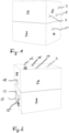
- eine perspektivische Ansicht eines geschlossenen Gehäuses eines ersten Beispiels eines erfindungsgemäßen Kopplungsmoduls;
- Fig. 2
- eine andere perspektivische Ansicht eines geschlossenen Gehäuses des in
Figur 1 gezeigten Kopplungsmodus; - Fig. 3
- eine Aufsicht auf das Kopplungsmodul der
Figur 1 mit entferntem Gehäuseoberteil, das ein im Gehäuseunterteil sitzendes Übersetzungsgetriebe zeigt; - Fig. 4
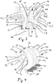
- eine perspektivische Ansicht eines Übersetzungsgetriebes des Kopplungsmoduls ohne Gehäuse;
- Fig. 5
- eine perspektive Ansicht von Teilen des Übersetzungsgetriebes der
Figur 4 mit einem ersten eingangsseitigen Getrieberad und einem ausgangsseitigen Getrieberad; - Fig. 6
- eine perspektive Ansicht von Teilen des Übersetzungsgetriebes der
Figur 4 mit einem zweiten eingangsseitigen Getrieberad und dem ausgangsseitigen Getrieberad; - Fig. 7
- eine perspektive Ansicht von Teilen des Übersetzungsgetriebes der
Figur 4 mit einem dritten eingangsseitigen Getrieberad und dem ausgangsseitigen Getrieberad; - Fig. 8
- eine Seitenansicht auf das geschlossene Kopplungsmodul der
Figur 1 ; - Fig. 9
- eine perspektivische Ansicht eines geschlossenen Gehäuses eines zweiten Beispiels eines erfindungsgemäßen Kopplungsmoduls;
- Fig. 10
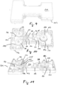
- eine perspektivische Aufsicht auf das Kopplungsmodul der
Figur 9 mit abgenommenem oberen Gehäuseteil; und - Fig. 11
- eine perspektivische Ansicht von unten auf das Kopplungsmodul der
Figur 9 mit abgenommenem unteren Gehäuseteil. - In den
Figuren 1 bis 8 ist ein erstes Ausführungsbeispiel eines erfindungsgemäßen Kopplungsmoduls gezeigt. Wie insbesondere in denFiguren 1 und 2 zu sehen ist, weist das Kopplungsmodul ein quaderförmiges Gehäuseoberteil 1 und ein Gehäuseunterteil 2 auf. In die schmalen Stirnseiten des Gehäuses 3, 4, 5, 6 sind Öffnungen 7, 8, 9, 11, 12, 13, 14, 15 für hier nicht dargestellte Bowdenzüge eingelassen, die als Kraftübertragungselemente zwischen hier ebenso nicht dargestellten Bremsbetätigungseinrichtungen und dem Kopplungsmodul bzw. dem Kopplungsmodul und mindestens einer Bremse wirken. Auch an der Oberseite 16 des Gehäuses sind Öffnungen 17, 18, 19, 21 für solche Kraftübertragungselemente vorgesehen. Wie inFigur 3 gezeigt ist, ist im Gehäuse ein Übersetzungsgetriebe 22 angeordnet. - In den
Figuren 3 bis 7 ist ein Übersetzungsgetriebe gezeigt, und zwar inFigur 3 vollständig innerhalb des geöffneten Gehäuses, inFigur 4 vollständig und ohne Gehäuse und in denFiguren 5 bis 7 jeweils ohne Gehäuse und lediglich in Teilen. Das Übersetzungsgetriebe 22 weist als wesentliche Bauteile eine feststehende Achse 23 und darauf drehbar gelagerte Getriebescheiben 24, 25, 26, 27 auf. Jede der Getriebescheiben 24, 25, 26, 27 weist einen ersten Scheibenabschnitt 28, 29, 31, 32 mit großem Außendurchmesser auf, wobei der große Außendurchmesser bei jeder der Getriebescheiben gleich ist. An der Unterseite jedes der ersten Scheibenabschnitte ist ein radial vorstehender Anschlag 33, 34, 35, 36 vorgesehen, der mit einer Anschlagkante 37 am Boden des Gehäuseunterteils 2 zusammenwirkt. Für jede der Getriebescheiben 24, 25, 26, 27 ist eine Rückstellfeder 38, 39, 41, 42 vorgesehen. Die Rückstellfeder 38, 39, 41, 42 sind jeweils an der Gehäuseinnenseite der schmalen Stirnseite 4 und den Anschlägen 33, 34, 35, 36 und drücken die Anschläge 33, 34, 35, 36 in Ruheposition an die Anschlagkante 37. Jede der Getriebescheiben 24, 25, 26, 27 weist zusätzlich einen zweiten Scheibenabschnitt 43, 44, 45, 46 auf, der mit dem ersten Scheibenabschnitt 28, 29, 42, 43 jeweils fest verbunden ist. Jeder der zweiten Scheibenabschnitte weist stirnseitig eine umlaufende Nut 47, 48, 49 auf. Darüber hinaus sind in jeden der zweiten Scheibenabschnitte stirnseitig jeweils um 90° versetzt vier ösenförmige, zur Stirnseite hin offene Aufnahmen 51x, 52x, 53x, 54x (x=1, 2, 3, 4) eingelassen. Die Aufnahmen dienen zum Einsetzen eines Nippels am Ende eines Zugseils, Zugkabels, Bowdenzuges oder eines anderen vergleichbaren Kraftübertragungselementes, und die umlaufenden Nuten 47, 48, 49, 50 dazu, ein Kraftübertragungselement um einen Abschnitt des Umfangs des jeweiligen zweiten Scheibenabschnitts zu führen. Die Außendurchmesser der zweiten Scheibenabschnitte 43, 44, 45 sind gleich und deutlich kleiner als der Außendurchmesser der ersten Scheibenabschnitte 28, 29, 31, 32. Demgegenüber entspricht der Außendurchmesser des zweiten Scheibenabschnitts 46 dem des Außendurchmessers der ersten Scheibenabschnitte 28, 29, 31, 32 und ist damit etwa doppelt so groß wie der Außendurchmesser der zweiten Scheibenabschnitte 43, 44, 45. - Die Getriebescheiben 24, 26 und 27 samt ihrer Aufnahmen 51x, 53x und 54x sind eingangsseitige Getriebeelemente zum Aufnehmen eingangsseitige Kraftübertragungselemente zur Aufnahme von Kräften von drei voneinander unabhängigen Bremsbetätigungseinrichtungen. Zur Übertragung von Drehmomenten in Richtung des Pfeils 55 weist jede der Getriebescheiben 24, 26 und 27 einen Mitnehmer 56, 57, 58 auf, der sich parallel zur Achse 23 erstreckt. Für die Mitnehmer 56, 57, 58 sind im ersten Scheibenabschnitt 29 der ausgangsseitigen Getriebescheibe 25 jeweils ein teilkreisförmiges Langloch 61, 62, 63 vorgesehen. In Ruheposition sitzt jeder der Mitnehmer 56, 57, 58 jeweils am in Pfeilrichtung vorderen Ende eines der Langlöcher 61, 62, 63. Wird die ausgangsseitige Getriebescheibe 25 durch eine der eingangsseitigen Getriebescheiben 24, 26 oder 28 ausgelenkt, können die anderen eingangsseitigen Getriebescheiben in ihrer Ruheposition verbleiben, da deren Mitnehmer in ihren Langlöchern an der ausgangsseitigen Getriebescheibe 25 frei laufen.
-
Fig. 8 zeigt, dass die Öffnungen 7, 8, 9, 11 mit jeweils einer der horizontalen Tangenten durch die umlaufenden Nuten 47, 48, 49, 50 der zweiten Scheibenabschnitte 43, 44, 45, 46 fluchten. Entsprechendes gilt für die Öffnungen 12, 13, 14, 15. Die Öffnungen 17, 18, 19, 21 fluchten mit jeweils einer der horizontalen Tangenten durch die umlaufenden Nuten 47, 48, 49, 50 der zweiten Scheibenabschnitte 43, 44, 45, 46. Damit ist es möglich, dem Übersetzungsgetriebe 22 Züge als Kraftübertragungselemente sowohl horizontal, als auch vertikal zuzuführen. Damit die Kraft eines eingangsseitigen, auf eine eingangsseitige Getriebescheibe 24, 26, 27 wirkenden Kraftübertragungselement auf ein ausgangsseitiges Kraftübertragungselement, das um die ausgangsseitige Getriebescheibe 25 herumgeführt ist, übertragen werden kann, müssen die eingangsseitigen Kraftübertragungselemente in einem Sinn um die eingangsseitigen Getriebescheiben herumgeführt werden, während das ausgangsseitige Kraftübertragungselement gegensinnig um die ausgangsseitige Getriebescheibe herumgeführt sein muss. Dabei bildet das Verhältnis der Radien einer umlaufenden Nut einer eingangsseitigen Getriebescheibe 24, 26, 27 zum Radius der umlaufenden Nut der ausgangsseitigen Getriebescheibe 25 das Übersetzungsverhältnis. Zwischen den eingangsseitigen Getriebescheiben 24, 26 und der ausgangsseitigen Getriebescheibe 25 beträgt das Übersetzungsverhältnis im gezeigten Ausführungsbeispiel etwa 1:1, zwischen der eingangsseitigen Getriebescheibe 27 und der ausgangsseitigen Getriebescheibe 25 beträgt das Übersetzungsverhältnis im gezeigten Ausführungsbeispiel etwa 2:1. - In den
Figuren 9 bis 11 ist ein anderes Ausführungsbeispiel eines erfindungsgemäßen Kopplungsmoduls, diesmal zum Kombinieren zweier Bremsbetätigungseinrichtungen, dargestellt. Das Kopplungsmodul weist ein im Grundriss hantelförmiges Gehäuse mit einer Oberseite 101 und einer Unterseite 102 auf. Eingangsseitig sind ein erstes Zugkabel 103, das von einer nicht dargestellten ersten Bremsbetätigungseinrichtung mit einer Zugkraft beaufschlagt werden kann, durch eine erste eingangsseitige Öffnung 104 und ein zweites Zugkabel 105, das von einer nicht dargestellten zweiten Bremsbetätigungseinrichtung mit einer Zugkraft beaufschlagt werden kann, durch eine zweite eingangsseitige Öffnung 106 geführt. Zusätzlich sind Scheibenräder 107, 108 zur Führung der Zugkabel 103, 105 vorgesehen. - Die Enden der Zugkabel 103, 105 sind jeweils mit einem nietenartigen Endstück 109, 111 versehen, die beide in einem Schlitten 112 verankert sind. Der Schlitten 112 ist in dem mittleren Gehäuseteil geführt und in Richtung der Längsachse des Gehäuses verschiebbar. Der Schlitten 112 und/oder die Endstücke 109, 111 sind über jeweils eine Rückstellfeder 113, 114 gegenüber im Gehäuseinneren vorgesehene Stege 115, 116 mit einer Rückstellkraft beaufschlagt.
- Auf der den Zugkabeln 103, 105 abgewandten Seite des Schlittens 112 ist eine mit diesem fest verbundene, sich quer zur Bewegungsrichtung des Schlittens erstreckende Wippe 117 angeordnet, an deren Enden jeweils ein Ende eines Bremszugs 118, 119 befestigt ist (hier nur im Ansatz gezeigt). Jedes der Bremszüge ist um etwa 90° um eine der beiden Umlenkrollen 121, 122 zur jeweiligen Ausgangsöffnung 123, 124 geführt.
- Wird eines der beiden Zugkabel 103, 105 gezogen, folgt der Schlitten 112 dem Zug entgegen der Kraft der Rückstellfeder 113, 114, die auf Seite des ziehenden Zugkabels wirkt. Das andere Zugkabel 103, 105 wird durch die Rückstellfeder 113, 114, die nicht auf der Seite des gezogenen Zugkabels wirkt, straff gehalten. Mit dem Schlitten 112 folgt auch die Wippe 117 dem Zug des einen Zugkabels 103, 105, so dass die Bremszüge 118, 119 angezogen und damit verbundene Bremsen betätigt werden. Die Wippe hat dabei die Funktion, etwaige Längenunterschiede in den Ansprechwegen der Bremsen auszugleichen, so dass an allen Bremsen die gleiche Kraft wirken kann.
- Mit dem gleichen Effekt kann anstelle der Wippe ein freilaufendes, horizontal liegendes Ausgleichsrad vorgesehen sein, dessen Achse fest mit dem Schlitten verbunden ist und an dem nicht wie bei der Wippe zwei Bremszüge befestigt sind, sondern um das ein Bremszug herum geführt ist, dessen Enden mit zwei verschiedenen Bremsen gekoppelt sind.
- Bei beiden gezeigten Ausführungsbeispielen ist es möglich, einer oder mehreren Bremsen unterschiedliche Funktionen zukommen zu lassen, insbesondere die Funktionen einer manuellen Betriebsbremse, einer Parkbremse oder einer Auflaufbremse.
-
- 1
- Gehäuseoberteil
- 2
- Gehäuseunterteil
- 3, 4
- schmale Stirnseiten Gehäuseoberteil
- 5, 6
- schmale Stirnseiten Gehäuseunterteil
- 7-9
- Öffnungen im Gehäuse
- 11-15
- Öffnungen im Gehäuse
- 16
- Oberseite des Gehäuses
- 17-19, 21
- Öffnungen im Gehäuse
- 22
- Übersetzungsgetriebe
- 23
- feststehende Achse
- 24-27
- Getriebescheiben
- 28, 29
- erste Scheibenabschnitte
- 31, 32
- erste Scheibenabschnitte
- 33-36
- radial vorstehende Anschläge
- 37
- Anschlagkante
- 38, 39, 41, 42
- Rückstellfedern
- 43-46
- zweite Scheibenabschnitte
- 47-50
- stirnseitig umlaufende Nuten
- 51x, 52x, 53x, 54x
- Aufnahmen
- 55
- Pfeil
- 56-58
- Mitnehmer
- 61-63
- Langlöcher
- 101
- oberer Gehäuseteil
- 102
- unterer Gehäuseteil
- 103
- Zugkabel
- 104
- eingangsseitige Öffnung
- 105
- Zugkabel
- 106
- eingansseitige Öffnung
- 107, 108
- Scheibenräder
- 109, 111
- Endstücke
- 112
- Schlitten
- 113, 114
- Rückstellfedern
- 115, 116
- Stege
- 117
- Wippe
- 118, 119
- Bremszüge
Claims (15)
- Kopplungsmodul zum Verbinden mindestens eines Bremsbetätigers mit mindestens einem Bremsauslöser zum Auslösen einer Bremse eines Anhängers für ein Leichtfahrzeug, gekennzeichnet durch mindestens zwei eingangsseitige Aufnahmen für eingangsseitige Kraftübertragungselemente zur Aufnahme von Kräften von zwei voneinander unabhängigen Bremsbetätigungseinrichtungen, und mit mindestens einer ausgangsseitigen Aufnahme für ein ausgangsseitiges Kraftübertragungselement zum Betätigen der mindestens einen Bremse, wobei die eingangsseitigen Aufnahmen mit der mindestens einen ausgansseitigen Aufnahme derart verbunden sind, dass bei Aufbringen einer Kraft von einer Bremsbetätigungseinrichtung auf eine der eingangsseitigen Aufnahmen eine Kraft auf die mindestens eine ausgangsseitige Aufnahme und damit auf einen damit verbundenen Bremsauslöser ausgeübt wird.
- Kopplungsmodul nach Anspruch 1, gekennzeichnet durch eine Übersetzungseinrichtung, so dass ein Übersetzungsverhältnis zwischen einer Kraft, die auf eine der eingangsseitigen Aufnahmen aufgebracht wird, und einer Kraft, die von der mindestens einen ausgangsseitigen Aufnahme übertragen wird, besteht.
- Kopplungsmodul nach Anspruch 2, dadurch gekennzeichnet, dass das Übersetzungsverhältnis zwischen der einen eingangsseitigen Aufnahme und der mindestens einen ausgangsseitigen Aufnahme von dem Übersetzungsverhältnis einer anderen eingangsseitigen Aufnahme und der mindestens einen ausgangsseitigen Aufnahme verschieden sind.
- Kopplungsmodul nach Anspruch 2 oder 3, gekennzeichnet durch mindestens einen Hebel als Übersetzungseinrichtung, wobei die eingangsseitigen und ausgangsseitigen Aufnahmen an mindestens dem einen Hebel ausgebildet sind und wobei sich das Übersetzungsverhältnis vorzugsweise aus den jeweiligen Abständen der eingangsseitigen Aufnahmen und der mindestens einen ausgangsseitigen Aufnahme zum Drehpunkt des Hebels ergibt.
- Kopplungsmodul nach einem der Ansprüche 2 bis 4, gekennzeichnet durch ein Getriebe, wobei die eingangsseitigen Aufnahmen und die mindestens eine ausgangsseitige Aufnahme auf mindestens einem Rotationselement sitzen, wobei sich das Übersetzungsverhältnis aus dem Abstand jeweils einer der eingangsseitigen Aufnahmen zur Drehachse des mindestens einen Rotationselements und dem Abstand der mindestens einen ausgangsseitigen Aufnahme zur Drehachse des mindestens einen Rotationselements ergibt.
- Kopplungsmodul nach Anspruch 5, dadurch gekennzeichnet, dass für die mindestens eine ausgangsseitige Aufnahme ein Rotationselement und für die eingangsseitigen Aufnahmen mindestens ein Rotationselement, vorzugsweise für jede eingangsseitige Aufnahme und für jede ausgangsseitige Aufnahme jeweils ein Rotationselement, vorgesehen sind, wobei mindestens zwei der Rotationselemente über einen Freilauf miteinander gekoppelt sind.
- Bremssystem für einen Anhänger für ein Leichtfahrzeug, mit mindestens einer Bremse und einem Bremsauslöser zum Auslösen der Bremse, wobei der Bremsauslöser auf der einen Seite mit der Bremse verbunden ist, und mindestens einer Bremsbetätigungseinrichtungen zur Verwirklichung mindestens einer Funktion ausgewählt aus der Gruppe von Parkbremse, Betriebsbremse und Auflaufbremse, gekennzeichnet durch mindestens zwei verschiedene Bremsbetätigungseinrichtungen zur Verwirklichung mindestens zweier verschiedener Funktionen ausgewählt aus der Gruppe von Parkbremse, manuellen Betriebsbremse und Auflaufbremse, und durch ein erstes Kopplungsmodul nach einem der vorstehenden Ansprüche, das die andere Seite des Bremsauslösers mit mindestens zwei der voneinander verschiedenen Bremsbetätigungseinrichtungen verbindet, so dass die Bremse mindestens zwei Funktionen ausgewählt aus der Gruppe von Parkbremse, manueller Betriebsbremse und Auflaufbremse erfüllen kann.
- Bremssystem nach Anspruch 7, dadurch gekennzeichnet, dass das Kopplungsmodul mit einer Federkraft beaufschlagt ist, die einer vom Bremsauslöser auf die Bremse ausgeübten Kraft entgegenwirkt.
- Bremssystem nach Anspruch 7 oder 8, dadurch gekennzeichnet, dass eine der Bremsbetätigungseinrichtungen einen Stellantrieb für eine feststellbare Parkbremse aufweist, der auf das Kopplungsmodul wirkt, insbesondere ein mittelbar oder unmittelbar auf das Kopplungsmodul wirkender, feststellbarer Bremshebel oder ein Motor zur Verwirklichung der Funktion einer Parkbremse, und/oder dass eine der Bremsbetätigungseinrichtungen eingerichtet ist, zur Verwirklichung der Funktion einer Auflaufbremse in Abhängigkeit von der Relativgeschwindigkeit zwischen Fahrzeug und Anhänger auf das Kopplungsmodul zu wirken, und/oder das eine der Bremsbetätigungseinrichtungen eine manuell betätigbare, nicht feststellbare und auf das Kopplungsmodul wirkende Bremsbetätigungseinrichtung zur Verwirklichung einer manuellen Betriebsbremse ist.
- Bremssystem nach einem der Ansprüche 7 bis 9, dadurch gekennzeichnet, dass mindestens eine der Bremsbetätigungseinrichtungen eingerichtet ist, eine Zugkraft auf das Kopplungsmodul auszuüben und insbesondere eine Zugstange, ein Zugseil oder einen Bowdenzug aufweist.
- Bremssystem nach einem der Ansprüche 7 bis 10, dadurch gekennzeichnet, dass mindestens eine der Bremsbetätigungseinrichtungen mit einer Rückstelleinrichtung, insbesondere einer Rückstellfeder, ausgerüstet ist.
- Bremssystem nach einem der Ansprüche 7 bis 11, dadurch gekennzeichnet, dass Kopplungsmoduldas Kopplungsmodul über einen ausgangsseitig vorgesehenen Bremszug auf die Bremse wirkt.
- Bremssystem nach einem der Ansprüche 7 bis 12, gekennzeichnet durch mindestens zwei Bremsen, die über einen gemeinsamen Bremszug ausgelöst werden, und durch ein zweites Kopplungsmodul mit einem Rad, wobei das Rad verschieblich ist, wobei die Drehachse des Rades von der mindestens einen ausgangsseitigen Aufnahme des ersten Kopplungsmoduls über ein ausgangsseitiges Kraftübertragungselement mit einer Kraft beaufschlagt werden kann, und wobei der Bremszug um einen Teil des Radumfangs des Rades geführt ist, so dass sich das Rad bei Aufbringen einer Kraft durch das ausgangsseitige Kraftübertragungselement in Kraftrichtung verschieben und damit eine Zugkraft auf den Bremszug ausüben kann.
- Bremssystem nach Anspruch 13, dadurch gekennzeichnet, dass der gemeinsame Bremszug auf jeder Seite zwischen Rad und Bremse über eine Umlenkrolle geführt ist.
- Anhänger für ein Leichtfahrzeug, insbesondere Fahrrad oder Pedelec, mit einem Bremssystem nach einem der Ansprüche 7 bis 14.
Applications Claiming Priority (1)
| Application Number | Priority Date | Filing Date | Title |
|---|---|---|---|
| DE202023103455.1U DE202023103455U1 (de) | 2023-06-21 | 2023-06-21 | Bremssystem |
Publications (2)
| Publication Number | Publication Date |
|---|---|
| EP4480765A1 true EP4480765A1 (de) | 2024-12-25 |
| EP4480765B1 EP4480765B1 (de) | 2026-04-01 |
Family
ID=93015866
Family Applications (1)
| Application Number | Title | Priority Date | Filing Date |
|---|---|---|---|
| EP24183783.0A Active EP4480765B1 (de) | 2023-06-21 | 2024-06-21 | Bremssystem |
Country Status (2)
| Country | Link |
|---|---|
| EP (1) | EP4480765B1 (de) |
| DE (1) | DE202023103455U1 (de) |
Citations (11)
| Publication number | Priority date | Publication date | Assignee | Title |
|---|---|---|---|---|
| US3666060A (en) * | 1969-11-27 | 1972-05-30 | Hans O Schroter | Service and parking brake arrangement for trailer vehicles |
| DE9410842U1 (de) * | 1994-07-07 | 1995-08-10 | Bernhard, Uwe, 71404 Korb | Vorrichtung zum Abbremsen, vorzugsweise eines Fahrrad-Anhängers |
| EP0805083A2 (de) * | 1996-04-29 | 1997-11-05 | BPW Bergische Achsen Kommanditgesellschaft | Zugvorrichtung für Fahrzeuganhänger |
| WO2008017941A2 (de) | 2006-08-08 | 2008-02-14 | Christian Steger-Vonmetz | Anhänger mit auflaufbremse |
| EP2022688A2 (de) * | 2007-08-06 | 2009-02-11 | BPW Fahrzeugtechnik GmbH & Co. KG | Zusatzbremssystem und Lösevorrichtung für Zusatzbremssysteme zur Betätigung der Bremsen auflaufgebremster Anhängerfahrzeuge |
| DE102008029990A1 (de) | 2008-06-24 | 2009-12-31 | Schaeffler Kg | Anhänger für ein Fahrzeug mit einer Auflaufbremse |
| DE102008044865A1 (de) | 2008-08-28 | 2010-03-04 | Schaeffler Kg | Bremseinrichtung für einen Fahrzeuganhänger |
| DE102013006913A1 (de) * | 2013-04-22 | 2014-10-23 | Milan Mertlik | Bremsvorrichtung für Anhänger |
| DE202018100310U1 (de) | 2018-01-19 | 2019-04-24 | Croozer Gmbh | Drahtlose Bremssteuerung |
| US11136031B2 (en) * | 2016-02-18 | 2021-10-05 | Nuewiel Gmbh | Motor-driven trailer and a method for controlling a motor-driven trailer |
| DE102022101063A1 (de) * | 2022-01-18 | 2023-07-20 | Schaeffler Technologies AG & Co. KG | Bremssystem für ein Fahrradgespann |
-
2023
- 2023-06-21 DE DE202023103455.1U patent/DE202023103455U1/de active Active
-
2024
- 2024-06-21 EP EP24183783.0A patent/EP4480765B1/de active Active
Patent Citations (12)
| Publication number | Priority date | Publication date | Assignee | Title |
|---|---|---|---|---|
| US3666060A (en) * | 1969-11-27 | 1972-05-30 | Hans O Schroter | Service and parking brake arrangement for trailer vehicles |
| DE9410842U1 (de) * | 1994-07-07 | 1995-08-10 | Bernhard, Uwe, 71404 Korb | Vorrichtung zum Abbremsen, vorzugsweise eines Fahrrad-Anhängers |
| EP0805083A2 (de) * | 1996-04-29 | 1997-11-05 | BPW Bergische Achsen Kommanditgesellschaft | Zugvorrichtung für Fahrzeuganhänger |
| WO2008017941A2 (de) | 2006-08-08 | 2008-02-14 | Christian Steger-Vonmetz | Anhänger mit auflaufbremse |
| AT504023A1 (de) | 2006-08-08 | 2008-02-15 | Christian Steger-Vonmetz | Anhänger mit auflaufbremse |
| EP2022688A2 (de) * | 2007-08-06 | 2009-02-11 | BPW Fahrzeugtechnik GmbH & Co. KG | Zusatzbremssystem und Lösevorrichtung für Zusatzbremssysteme zur Betätigung der Bremsen auflaufgebremster Anhängerfahrzeuge |
| DE102008029990A1 (de) | 2008-06-24 | 2009-12-31 | Schaeffler Kg | Anhänger für ein Fahrzeug mit einer Auflaufbremse |
| DE102008044865A1 (de) | 2008-08-28 | 2010-03-04 | Schaeffler Kg | Bremseinrichtung für einen Fahrzeuganhänger |
| DE102013006913A1 (de) * | 2013-04-22 | 2014-10-23 | Milan Mertlik | Bremsvorrichtung für Anhänger |
| US11136031B2 (en) * | 2016-02-18 | 2021-10-05 | Nuewiel Gmbh | Motor-driven trailer and a method for controlling a motor-driven trailer |
| DE202018100310U1 (de) | 2018-01-19 | 2019-04-24 | Croozer Gmbh | Drahtlose Bremssteuerung |
| DE102022101063A1 (de) * | 2022-01-18 | 2023-07-20 | Schaeffler Technologies AG & Co. KG | Bremssystem für ein Fahrradgespann |
Also Published As
| Publication number | Publication date |
|---|---|
| EP4480765B1 (de) | 2026-04-01 |
| DE202023103455U1 (de) | 2024-09-24 |
Similar Documents
| Publication | Publication Date | Title |
|---|---|---|
| DE69413937T2 (de) | Steuersystem für ein Arbeitgerät an einem Fahrrad | |
| DE102016011361B4 (de) | Elektronische scheibenbremse | |
| DE3930374A1 (de) | Mehrgang-antriebsnabe mit mehr als drei gaengen | |
| EP0373368A1 (de) | Vorrichtung zum Verriegeln eines Betätigungshebels einer Schaltvorrichtung eines Gangwechselgetriebes in einer einem bestimmten Schaltzustand oder Schaltprogramm zugehörigen Hebelstellung in Abhängigkeit von einem Bremspedal | |
| DE102021205035A1 (de) | Kolbenbaugruppe für menschlich angetriebenes fahrzeug | |
| DE102021205009A1 (de) | Kolbenbaugruppe für menschlich angetriebenes fahrzeug | |
| EP3599154A1 (de) | Antriebsanordnung und fahrzeug | |
| EP2022688B1 (de) | Zusatzbremssystem und Lösevorrichtung für Zusatzbremssysteme zur Betätigung der Bremsen auflaufgebremster Anhängerfahrzeuge | |
| EP4480765B1 (de) | Bremssystem | |
| DE2945132C2 (de) | Vorrichtung zur Spieleinstellung, insbesondere für Kraftfahrzeug-Kupplungen | |
| DE102004009331B4 (de) | Betätigungsmechanismus für Bowdenzüge | |
| DE10029752C1 (de) | Feststellbremse | |
| EP0518159B1 (de) | Stellvorrichtung für eine an einem Fahrzeug vorgesehene Komponente | |
| DE102021205032A1 (de) | Kolbenbaugruppe für menschlich angetriebenes fahrzeug | |
| DE10259448B4 (de) | Lenkrolle | |
| DE3505325A1 (de) | Einrichtung zum reibungsfreien kuppeln, welche ein wahlweises abkuppeln einer abtriebswelle von einer antriebswelle erlaubt und gleichzeitig wenigstens eine bremsung der abgekuppelten abtriebswelle bewirkt, mit derartigen einrichtungen versehene motor-achsanordnung und mit einer derartigen achsanordnung versehenes einachsiges motorfahrzeug | |
| DE102008063825A1 (de) | Lenk- und Bremsvorrichtung für Fahrzeuge | |
| DE102010020669A1 (de) | Vorrichtung zum Bremsen, Lenken und Fesstellen eines manuellen Rollstuhls | |
| WO1999011512A1 (de) | Kupplungseinrichtung | |
| DE102016006297A1 (de) | Transportmittel mit fernsteuerbarer Arretierung | |
| DE9410842U1 (de) | Vorrichtung zum Abbremsen, vorzugsweise eines Fahrrad-Anhängers | |
| DE3709418A1 (de) | Handbremse fuer kraftfahrzeuge | |
| DE102021122592B4 (de) | Schaltsystem und Getriebeeinheit mit einem Schaltsystem, insbesondere für ein Zweirad | |
| EP1050424A2 (de) | Wegrollsicherung für Kraftfahrzeuge | |
| DE3014136C2 (de) | Kupplungs- und Lenkvorrichtung |
Legal Events
| Date | Code | Title | Description |
|---|---|---|---|
| PUAI | Public reference made under article 153(3) epc to a published international application that has entered the european phase |
Free format text: ORIGINAL CODE: 0009012 |
|
| STAA | Information on the status of an ep patent application or granted ep patent |
Free format text: STATUS: THE APPLICATION HAS BEEN PUBLISHED |
|
| AK | Designated contracting states |
Kind code of ref document: A1 Designated state(s): AL AT BE BG CH CY CZ DE DK EE ES FI FR GB GR HR HU IE IS IT LI LT LU LV MC ME MK MT NL NO PL PT RO RS SE SI SK SM TR |
|
| STAA | Information on the status of an ep patent application or granted ep patent |
Free format text: STATUS: REQUEST FOR EXAMINATION WAS MADE |
|
| 17P | Request for examination filed |
Effective date: 20250625 |
|
| GRAP | Despatch of communication of intention to grant a patent |
Free format text: ORIGINAL CODE: EPIDOSNIGR1 |
|
| STAA | Information on the status of an ep patent application or granted ep patent |
Free format text: STATUS: GRANT OF PATENT IS INTENDED |
|
| INTG | Intention to grant announced |
Effective date: 20251110 |
|
| GRAS | Grant fee paid |
Free format text: ORIGINAL CODE: EPIDOSNIGR3 |
|
| GRAA | (expected) grant |
Free format text: ORIGINAL CODE: 0009210 |
|
| STAA | Information on the status of an ep patent application or granted ep patent |
Free format text: STATUS: THE PATENT HAS BEEN GRANTED |
|
| AK | Designated contracting states |
Kind code of ref document: B1 Designated state(s): AL AT BE BG CH CY CZ DE DK EE ES FI FR GB GR HR HU IE IS IT LI LT LU LV MC ME MK MT NL NO PL PT RO RS SE SI SK SM TR |
|
| REG | Reference to a national code |
Ref country code: CH Ref legal event code: F10 Free format text: ST27 STATUS EVENT CODE: U-0-0-F10-F00 (AS PROVIDED BY THE NATIONAL OFFICE) Effective date: 20260401 Ref country code: GB Ref legal event code: FG4D Free format text: NOT ENGLISH |
|
| REG | Reference to a national code |
Ref country code: DE Ref legal event code: R096 Ref document number: 502024000967 Country of ref document: DE |
|
| REG | Reference to a national code |
Ref country code: IE Ref legal event code: FG4D Free format text: LANGUAGE OF EP DOCUMENT: GERMAN |