EP4480673A2 - Beschichtungsvorrichtung - Google Patents
Beschichtungsvorrichtung Download PDFInfo
- Publication number
- EP4480673A2 EP4480673A2 EP24182669.2A EP24182669A EP4480673A2 EP 4480673 A2 EP4480673 A2 EP 4480673A2 EP 24182669 A EP24182669 A EP 24182669A EP 4480673 A2 EP4480673 A2 EP 4480673A2
- Authority
- EP
- European Patent Office
- Prior art keywords
- gripping
- film
- gripping means
- coating apparatus
- coated
- Prior art date
- Legal status (The legal status is an assumption and is not a legal conclusion. Google has not performed a legal analysis and makes no representation as to the accuracy of the status listed.)
- Pending
Links
- 239000011248 coating agent Substances 0.000 title claims abstract description 64
- 238000000576 coating method Methods 0.000 title claims abstract description 64
- 230000003028 elevating effect Effects 0.000 claims abstract description 47
- 238000010438 heat treatment Methods 0.000 claims description 28
- 230000007246 mechanism Effects 0.000 claims description 28
- 238000010586 diagram Methods 0.000 description 24
- 238000004519 manufacturing process Methods 0.000 description 8
- 229920005992 thermoplastic resin Polymers 0.000 description 5
- 238000004804 winding Methods 0.000 description 5
- 238000004891 communication Methods 0.000 description 4
- 238000003860 storage Methods 0.000 description 4
- 238000001514 detection method Methods 0.000 description 3
- 238000000034 method Methods 0.000 description 3
- 238000009966 trimming Methods 0.000 description 3
- 238000001035 drying Methods 0.000 description 2
- 230000037303 wrinkles Effects 0.000 description 2
- 239000000654 additive Substances 0.000 description 1
- 239000000853 adhesive Substances 0.000 description 1
- 230000001070 adhesive effect Effects 0.000 description 1
- 239000003963 antioxidant agent Substances 0.000 description 1
- 230000003078 antioxidant effect Effects 0.000 description 1
- 239000012298 atmosphere Substances 0.000 description 1
- 239000002981 blocking agent Substances 0.000 description 1
- 239000000919 ceramic Substances 0.000 description 1
- 238000011109 contamination Methods 0.000 description 1
- 239000000428 dust Substances 0.000 description 1
- 239000011521 glass Substances 0.000 description 1
- 230000001678 irradiating effect Effects 0.000 description 1
- 239000004611 light stabiliser Substances 0.000 description 1
- 239000000314 lubricant Substances 0.000 description 1
- 238000003754 machining Methods 0.000 description 1
- -1 matte Substances 0.000 description 1
- 239000002184 metal Substances 0.000 description 1
- 238000000465 moulding Methods 0.000 description 1
- 230000035699 permeability Effects 0.000 description 1
- 239000000049 pigment Substances 0.000 description 1
- 230000001681 protective effect Effects 0.000 description 1
- 229920005989 resin Polymers 0.000 description 1
- 239000011347 resin Substances 0.000 description 1
- 238000007493 shaping process Methods 0.000 description 1
- 239000000126 substance Substances 0.000 description 1
- 239000000758 substrate Substances 0.000 description 1
- 229920001187 thermosetting polymer Polymers 0.000 description 1
- 238000011144 upstream manufacturing Methods 0.000 description 1
- XLYOFNOQVPJJNP-UHFFFAOYSA-N water Substances O XLYOFNOQVPJJNP-UHFFFAOYSA-N 0.000 description 1
Images








Classifications
-
- B—PERFORMING OPERATIONS; TRANSPORTING
- B32—LAYERED PRODUCTS
- B32B—LAYERED PRODUCTS, i.e. PRODUCTS BUILT-UP OF STRATA OF FLAT OR NON-FLAT, e.g. CELLULAR OR HONEYCOMB, FORM
- B32B38/00—Ancillary operations in connection with laminating processes
- B32B38/18—Handling of layers or the laminate
- B32B38/1825—Handling of layers or the laminate characterised by the control or constructional features of devices for tensioning, stretching or registration
- B32B38/1833—Positioning, e.g. registration or centering
-
- B—PERFORMING OPERATIONS; TRANSPORTING
- B29—WORKING OF PLASTICS; WORKING OF SUBSTANCES IN A PLASTIC STATE IN GENERAL
- B29C—SHAPING OR JOINING OF PLASTICS; SHAPING OF MATERIAL IN A PLASTIC STATE, NOT OTHERWISE PROVIDED FOR; AFTER-TREATMENT OF THE SHAPED PRODUCTS, e.g. REPAIRING
- B29C63/00—Lining or sheathing, i.e. applying preformed layers or sheathings of plastics; Apparatus therefor
- B29C63/0004—Component parts, details or accessories; Auxiliary operations
-
- B—PERFORMING OPERATIONS; TRANSPORTING
- B29—WORKING OF PLASTICS; WORKING OF SUBSTANCES IN A PLASTIC STATE IN GENERAL
- B29C—SHAPING OR JOINING OF PLASTICS; SHAPING OF MATERIAL IN A PLASTIC STATE, NOT OTHERWISE PROVIDED FOR; AFTER-TREATMENT OF THE SHAPED PRODUCTS, e.g. REPAIRING
- B29C63/00—Lining or sheathing, i.e. applying preformed layers or sheathings of plastics; Apparatus therefor
- B29C63/0073—Lining or sheathing, i.e. applying preformed layers or sheathings of plastics; Apparatus therefor of non-flat surfaces, e.g. curved, profiled
-
- B—PERFORMING OPERATIONS; TRANSPORTING
- B29—WORKING OF PLASTICS; WORKING OF SUBSTANCES IN A PLASTIC STATE IN GENERAL
- B29C—SHAPING OR JOINING OF PLASTICS; SHAPING OF MATERIAL IN A PLASTIC STATE, NOT OTHERWISE PROVIDED FOR; AFTER-TREATMENT OF THE SHAPED PRODUCTS, e.g. REPAIRING
- B29C63/00—Lining or sheathing, i.e. applying preformed layers or sheathings of plastics; Apparatus therefor
- B29C63/0091—Lining or sheathing, i.e. applying preformed layers or sheathings of plastics; Apparatus therefor in particular atmospheres
-
- B—PERFORMING OPERATIONS; TRANSPORTING
- B29—WORKING OF PLASTICS; WORKING OF SUBSTANCES IN A PLASTIC STATE IN GENERAL
- B29C—SHAPING OR JOINING OF PLASTICS; SHAPING OF MATERIAL IN A PLASTIC STATE, NOT OTHERWISE PROVIDED FOR; AFTER-TREATMENT OF THE SHAPED PRODUCTS, e.g. REPAIRING
- B29C63/00—Lining or sheathing, i.e. applying preformed layers or sheathings of plastics; Apparatus therefor
- B29C63/02—Lining or sheathing, i.e. applying preformed layers or sheathings of plastics; Apparatus therefor using sheet or web-like material
-
- B—PERFORMING OPERATIONS; TRANSPORTING
- B32—LAYERED PRODUCTS
- B32B—LAYERED PRODUCTS, i.e. PRODUCTS BUILT-UP OF STRATA OF FLAT OR NON-FLAT, e.g. CELLULAR OR HONEYCOMB, FORM
- B32B38/00—Ancillary operations in connection with laminating processes
- B32B38/0036—Heat treatment
-
- B—PERFORMING OPERATIONS; TRANSPORTING
- B32—LAYERED PRODUCTS
- B32B—LAYERED PRODUCTS, i.e. PRODUCTS BUILT-UP OF STRATA OF FLAT OR NON-FLAT, e.g. CELLULAR OR HONEYCOMB, FORM
- B32B2309/00—Parameters for the laminating or treatment process; Apparatus details
- B32B2309/12—Pressure
Definitions
- the present invention relates to a coating apparatus.
- a molding method is known in which a work to be coated that has a three-dimensional shape is coated with a film.
- Japanese Patent Laid-Open No. 2021-62625 discloses a method for coating an automobile or the like with a film stretched out in a flat planar shape.
- An object of the present invention is to suppress variation in the amount of stretch of a film depending on the part of a work to be coated.
- the present invention in an aspect provides a coating apparatus as specified in claims 1 to 16.
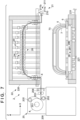
- FIG. 1 is a schematic diagram showing part of a configuration of a production line 100 to which a coating apparatus 2 of the present invention can be applied.
- arrows X and Y indicate horizontal directions that are perpendicular to each other
- arrow Z indicates an up-down direction (height direction of the coating apparatus).
- a work to be coated 5 is described as being a component such as a front bumper or rear bumper of a vehicle (e.g., a four-wheeled vehicle), but the work to be coated 5 is not limited to these, and the present invention can be applied to various objects.
- the production line 100 includes a conveying system 1 for conveying the work to be coated 5, the coating apparatus 2 for coating the work to be coated 5 with a film 4, and a control apparatus 3 for performing overall control of the production line 100.
- the arrows in the drawing indicate the conveying direction.
- FIG. 1 shows a state in which a work to be coated 5 is conveyed from a conveying path 10 on an upstream side of the conveying system 1, and the work to be coated 5 is coated with the film 4 inside the coating apparatus 2, and thereafter conveyed to a conveying path 11 on a downstream side.
- the conveying system 1 is, for example, a conveying apparatus such as a belt conveyor.
- the work to be coated 5 is conveyed by the conveying system 1 while being held by a jig 7 placed on a conveying platform 6 such as a pallet.
- the conveying system 1 may further include, for example, a conveying position adjustment unit or the like that adjusts the conveying position of the conveying platform 6.
- the conveying system 1 is not limited to the conveying apparatus described above, and the work to be coated 5 may also be conveyed using a robot arm or the like.
- the coating apparatus 2 is a device that coats the work to be coated 5 with the film 4, using a later-described configuration.
- the work to be coated 5 which is a member such as a vehicle bumper, is coated with the film 4.
- This makes it possible to easily decorate a member of a vehicle by, for example, changing the color of the film 4 in accordance with the vehicle color.
- a film 4 having a printed pattern such as a woodgrain pattern, or a texture such as metal, matte, or glass
- a film 4 having functionality such as water repellency, weather resistance, heat shielding properties, and electromagnetic wave permeability, it is possible to impart functionality to a member of a vehicle.
- the control apparatus 3 performs overall control of the production line 100.
- the control apparatus 3 includes a processing unit, a storage unit, an input/output interface (I/O), a communication unit, and the like.
- the processing unit is a processor represented by a CPU, and controls each apparatus on the production line 100 by executing programs stored in the storage unit.
- the storage unit is a storage device such as a ROM, a RAM, or an HDD, and stores various types of control information in addition to the programs to be executed by the processing unit.
- the I/O is an interface that transmits and receives signals between the processing unit and an external apparatus.
- the communication unit is a communication device that communicates with the above-mentioned apparatuses or other control apparatuses via a communication line.
- the production line 100 is not limited to the configuration described above, and may also include, for example, a robot apparatus for replacing the work to be coated 5 or the jig 7 and the like, a dust removal apparatus for removing contamination from the work to be coated 5, a light irradiation unit for irradiating the work to be coated 5 and the film 4 with light such as ultraviolet light, a drying unit for drying the work to be coated 5 and the film 4, a trimming unit for partially removing the film 4 coating the work to be coated 5 using a laser or a trimming cutter, or the like.
- a robot apparatus for replacing the work to be coated 5 or the jig 7 and the like
- a dust removal apparatus for removing contamination from the work to be coated 5
- a light irradiation unit for irradiating the work to be coated 5 and the film 4 with light such as ultraviolet light
- a drying unit for drying the work to be coated 5 and the film 4
- a trimming unit for partially removing the film 4 coating the work to be coated 5 using
- the coating apparatus 2 in this embodiment includes a film support unit 20, a film conveying unit 21, a chamber 22, and an air pressure adjustment unit 23.
- the film 4 supported by the film support unit 20 is conveyed into the chamber 22 by the film conveying unit 21.
- the dotted line portion of the chamber 22 shown in FIG. 1 represents the inside of the chamber 22.
- the coating apparatus 2 includes the configuration described below inside the chamber 22, and coats the work to be coated 5 with the film 4. During coating, the air pressure inside the chamber 22 is adjusted by the air pressure adjustment unit 23.
- FIG. 2 is a schematic diagram showing part of a cross section of the coating apparatus 2 in the conveying direction of the film 4.
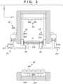
- FIG. 3 is a schematic diagram showing part of a cross section of the coating apparatus 2 in the conveying direction of the work to be coated 5.
- the conveying direction of the film 4 is referred to as the X direction
- the conveying direction of the work to be coated 5 is referred to as the Y direction in some cases.
- the film support unit 20 supports the film 4 that is to coat the work to be coated 5.
- the film support unit 20 includes a support platform 200, a support shaft 201, a winding shaft 202, a guide shaft 203, a cutter 204, a winding shaft 205, and the like.
- the support shaft 201 provided on the support platform 200 is a shaft that rotatably supports the film 4 wound in a roll shape.
- the winding shaft 202 and the winding shaft 205 are shafts for winding a mold-release film, for example, when the front and back surfaces of the film 4 that is to coat the work to be coated 5 are laminated with a mold-release film, or the like.
- the guide shaft 203 is a shaft that pulls out the film 4 supported by the support shaft 201 and supplies the film 4 horizontally.
- the cutter 204 cuts the film 4 after the film 4 is conveyed by the later-described film conveying unit 21.
- the cutter 204 may cut the film 4 by, for example, sliding a trimming cutter, a laser, or the like in the width direction of the film 4.
- the width direction of the film 4 is the axial direction of the roll-shaped film 4.
- a film including a layer of thermoplastic resin may be used.
- a layer of thermoplastic resin may be formed from, for example, a plurality of types of thermoplastic resins.
- the layer of thermoplastic resin may contain additives such as an anti-blocking agent, a lubricant, an antioxidant, a light stabilizer, a pigment, a dye, and an inorganic substance.
- the film 4 may also include a vapor deposited layer, a printed layer, a peeling layer, and the like.
- one surface of the film 4 may be coated with an adhesive or the like.
- the film 4 may also be laminated with, for example, a peelable protective film.
- minute patterns, recesses and protrusions, and the like may be formed on the surface of the film 4 through shaping, laser machining, or the like.
- the film conveying unit 21 conveys the film 4 above the work to be coated 5 conveyed inside the chamber 22.
- the film conveying unit 21 includes a leading end gripping portion 210 and a film moving mechanism 211.
- the leading end gripping portion 210 is switchable between a gripping state of gripping the leading end of the roll-shaped film 4 pulled out in a direction perpendicular to the axial direction, and a release state of not gripping but releasing the leading end of the film 4.
- the film conveying unit 21 is provided in a later-described upper chamber 220, and is raised and lowered in the up-down direction of the coating apparatus 2 together with the upper chamber 220.
- the film moving mechanism 211 includes a leading end support member 211a that movably supports the leading end gripping portion 210, and an actuator 211b that is arranged on both side walls of the upper chamber 220.
- the actuator 211b is provided horizontally along the conveying direction of the film 4.
- the conveying direction of the film 4 is a direction perpendicular to the axial direction of the roll-shaped film 4.
- the actuator 211b may be, for example, an electric cylinder or an electric ball screw mechanism.
- the length of actuator 211b is longer than the length of the upper chamber 220 in the conveying direction of the film 4, as shown in FIG. 2 . This can prevent the leading end gripping portion 210 from coming into contact with the lower chamber 221 when the upper chamber 220 is lowered.
- the chamber 22 is a box-shaped apparatus inside of which a vacuum atmosphere can be maintained.
- the chamber 22 includes an upper chamber 220 with an open bottom surface and a lower chamber 221 with an open top surface.
- the upper chamber 220 can be raised and lowered in the up-down direction of the coating apparatus 2, and for example, is raised and lowered by an actuator (not shown) such as an electric cylinder or an electric ball screw mechanism provided on the outer walls of the lower chamber 221 and the upper chamber 220.
- an actuator such as an electric cylinder or an electric ball screw mechanism provided on the outer walls of the lower chamber 221 and the upper chamber 220.
- the upper chamber 220 is raised to be spaced apart from the lower chamber 221 as shown in FIG. 2 .
- the air pressure inside the chamber 22 is adjusted by the air pressure adjustment unit 23 described below, the upper chamber 220 is lowered to come into contact with the lower chamber 221, whereby the inside of chamber 22 can be kept airtight (see FIGS. 10 to 13 ).
- the coating apparatus 2 includes, inside the chamber 22, a plurality of first gripping units 24, a plurality of second gripping units 25, a plurality of first elevating units 26, a plurality of second elevating units 27, and a work elevating unit 28. Also, as shown in FIGS. 2 and 3 , the coating apparatus 2 includes a plurality of heating units 29 inside the chamber 22.
- a plurality of first gripping units 24 and a plurality of second gripping units 25 are aligned along the film conveying direction, and grip the film 4 conveyed by film conveying unit 21.
- the plurality of first gripping units 24 and the plurality of second gripping units 25 are arranged at positions opposing each other.
- the plurality of first gripping units 24 grip a side of the film 4.
- the plurality of second gripping units 25 grip a side of the film 4 opposite to the side gripped by the plurality of first gripping units 24.
- the plurality of first gripping units 24 are provided on the later-described plurality of first elevating units 26 and can be raised and lowered in the up-down direction of the coating apparatus 2.
- FIG. 2 shows an example of the configuration of the plurality of first gripping units 24, but as shown in FIG. 3 , the plurality of second gripping units 25 also have a configuration similar to the configuration of the plurality of first gripping units 24 shown in FIG. 2 . That is, the plurality of second gripping units 25 are provided on the plurality of second elevating units 27 and can be raised and lowered in the up-down direction of the coating apparatus 2.
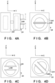
- FIGS. 4A to 4D Each of the plurality of first gripping units 24 and the plurality of second gripping units 25 will be described with reference to FIGS. 4A to 4D .
- a gripping unit 24 will be described, but a gripping unit 25 has a similar configuration.
- FIG. 4A is a schematic diagram of the gripping unit 24 as viewed in the X direction, and corresponds to an enlarged view of one of the gripping units 24 in FIG. 3 .
- FIGS. 4B to 4D are schematic diagrams of the gripping unit 24 as viewed in the Y direction, and correspond to enlarged views of the gripping unit 24 in FIG. 2 .
- the gripping unit 24 includes gripping portions 240 and support portions 241.
- the gripping portions 240 in this embodiment are a pair of plate-shaped elastic members that sandwich the film 4.
- the elastic member may be, for example, a plate-shaped member made of a thermoplastic resin, a thermosetting resin, or the like.
- the gripping portion 240 in this embodiment can switch between a gripping state of gripping the film 4 as shown in FIG. 4B and a release state of not gripping but releasing the film 4 as shown in FIG. 4C .
- the gripping state is a state in which the gripping portions 240 are closed
- the release state is, in other words, in a state in which the gripping portions 240 are open.
- Switching between the gripping state and the release state of the gripping portions 240 may also be controlled by, for example, an actuator or the like provided inside the support portion 241 as shown in FIG. 4A .
- the actuator may be an electric cylinder, an electric ball screw mechanism, or the like.
- the gripping portions 240 in this embodiment may also be rotatable about the Y direction.
- the support portions 241 may include, for example, a rotation shaft as shown in FIG. 4A .
- the rotation of the rotation shaft may be controlled by an actuator provided in the support portions 241. Since the gripping portions 240 are rotatable, each of the gripping units 24 and 25 can adjust the orientation of gripping the film 4 when the plurality of first gripping units 24 and the plurality of second gripping units 25 are raised and lowered. In other words, the orientation of gripping the film 4 is the angle of the gripping portion 240 with respect to the X direction when gripping the film 4.
- the plurality of first elevating units 26 are aligned along a side of the film 4 being conveyed into the chamber 22, and the plurality of second elevating units 27 are aligned along a side opposing the side of the film 4 on the plurality of first elevating units 26 side.
- the plurality of first elevating units 26 and the plurality of second elevating units 27 are arranged at positions opposing each other.
- the plurality of first elevating units 26 have a plurality of first support members 261 that individually support the plurality of first gripping units 24, and a plurality of first moving mechanisms 260 that individually move the plurality of first support members 261 in the up-down direction.
- FIG. 2 shows a configuration of the plurality of first elevating units 26, the plurality of second elevating units 27 also have a similar configuration. That is, the plurality of second elevating units 27 have a plurality of second support members 271 that individually support the plurality of second gripping units 25, and a plurality of second moving mechanisms 270 that individually move the plurality of second support members 271 in the up-down direction (see FIG. 3 ).
- the plurality of first moving mechanisms 260 and the plurality of second moving mechanisms 270 may also be actuators, for example.
- the actuators are rod-shaped, and may be electric cylinders, electric ball screw mechanisms, or the like.
- the plurality of first moving mechanisms 260 and the plurality of second moving mechanisms 270 may be members that can expand and contract in the up-down direction of the coating apparatus 2, for example.
- the plurality of first elevating units 26 and the plurality of second elevating units 27 in this embodiment raise and lower sets of the first gripping units 24 and the second gripping units 25 arranged at positions opposing each other to the same heights as each other, among the plurality of the first gripping units 24 and the second gripping units 25 aligned at positions opposing each other (see FIG. 3 ).
- This makes it possible to adjust the height of the film 4 in the conveying direction in accordance with the shape of the work to be coated 5. Accordingly, compared to a case where the work to be coated 5 is coated with the film 4 while the film 4 is stretched out in a flat planar shape, the coating apparatus 2 in this embodiment can suppress changes in the amount of stretch of the film 4 depending on the part of the work to be coated 5.
- sets of the first gripping units 24 and the second gripping units 25 arranged at positions opposing each other may be raised and lowered to different heights (see FIG. 3 ). This allows the shape of the film 4 to be adjusted to suit various shapes of the work to be coated 5.
- the raising and lowering of the plurality of first elevating units 26 and the plurality of second elevating units 27 may be controlled by the control apparatus 3, for example, by measuring the shape of the work to be coated 5 in advance and storing the height of each part of the work to be coated 5 in the control apparatus 3.
- a detection unit such as a sensor for detecting the shape of the work to be coated 5 may be further provided inside the chamber 22 or in each of the elevating units 26 and 27, and the elevating units 26 and 27 may be raised or lowered according to the detection result of the detection unit.
- the work elevating unit 28 includes a work elevating portion 280 and a work conveying portion 281 supported by the work elevating portion 280.
- the work elevating portion 280 can raise and lower the work to be coated 5 carried into the chamber 22 in the up-down direction of the coating apparatus 2 to adjust the position of the work to be coated 5 or bring the work to be coated 5 into contact with the film 4.
- the work conveying portion 281 conveys the work to be coated 5 using a plurality of rotatable shafts.
- the work elevating portion 280 and the work conveying portion 281 may be, for example, actuators such as electric cylinders or electric ball screw mechanisms.
- each heating unit 29 heats the film 4 conveyed inside the chamber 22.
- each heating unit 29 is arranged to correspond to a set of a first gripping unit and a second gripping unit arranged opposing each other, is movable up and down, and can be adjusted. By heating the film 4 with the plurality of heating units 29, the conformability of the film 4 to the work to be coated 5 can be improved.
- Each heating unit 29 of the plurality of heating units 29 includes heating elements 290 and a support plate 291 that supports the heating elements 290.
- the support plate 291 is provided on a first moving mechanism 260 that raises and lowers a first gripping unit 24 and a second moving mechanism 270 that raises and lowers a second gripping unit 25, which are arranged at positions opposing each other, and is raised and lowered in synchronization with the corresponding set of the first gripping unit 24 and the second gripping unit 25.
- Each heating unit 29 is raised and lowered in synchronization with the corresponding first gripping unit 24 and second gripping unit 25, whereby the distance between each heating unit 29 and the film 4 can be kept constant.
- each heating unit 29 is provided on a first moving mechanism 260 that raises and lowers a first gripping unit 24 and a second moving mechanism 270 that raises and lowers a second gripping unit 25, which are arranged at positions opposing each other, but there is no limitation to this.
- each of the heating units 29 may be arranged on a side surface, top surface, or the like inside of the upper chamber 220.
- the heating unit 29 may be configured to adjust the heating position according to the shape of the film 4 using, for example, a deformable sheet-like heater such as a ceramic heater.
- each heating unit 29 may be set to a different temperature.
- the air pressure adjustment unit 23 includes an air pressure adjustment portion 230, a pipe 231, a valve 232, or the like, and adjusts the air pressure inside the chamber 22.
- the air pressure adjustment portion 230 includes, for example, a vacuum pump that reduces the pressure inside of the chamber 22 to create a vacuum state, and a compressor that increases the pressure inside of the chamber 22 with compressed air or the like.
- the pipe 231 is connected to the lower chamber 221, and the pressure reduction or pressure increase by the air pressure adjustment portion 230 can be adjusted by opening and closing the valve 232.
- the air pressure adjustment unit 23 adjusts the air pressure inside the chamber 22 while the plurality of first gripping units 24 and the plurality of second gripping units 25 are gripping the film 4, and causes the film 4 to coat the work to be coated 5.
- the plurality of first gripping units 24 are raised and lowered by the plurality of first elevating units 26, and the plurality of second gripping units 25 are raised and lowered by the plurality of second elevating units 27.
- the height of the film 4 gripped by the plurality of first gripping units 24 and the plurality of second gripping units 25 relative to the work to be coated 5 can be adjusted according to the shape of the work to be coated 5.
- FIGS. 5 to 15 are diagrams for illustrating operations of the coating apparatus 2, and show an example of operations from the carrying-in of the film 4 and the work to be coated 5, to coating and carry-out.
- FIG. 5 shows a state in which the work to be coated 5 and the film 4 have been conveyed inside the chamber 22.
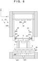
- FIG. 6 shows the inside of the chamber 22 in the X direction of FIG. 5 .
- the work to be coated 5 and the film 4 are conveyed while the upper chamber 220 is raised and the upper chamber 220 and the lower chamber 221 are spaced apart from each other.
- the work to be coated 5 is carried onto the work elevating unit 28 provided in the lower chamber 221 by, for example, the above-mentioned conveying system 1 or the like. After the work to be coated 5 is carried into the chamber 22, its position may be adjusted by the work elevating unit 28. The film 4 is conveyed above the work to be coated 5 by the film conveying unit 21.
- the film conveying unit 21 conveys the film 4 such that a side of the film 4 being conveyed passes through a path that can be gripped by the plurality of first gripping units 24, and the side opposing the side of the film 4 on the plurality of first gripping units 24 side passes through a path that can be gripped by the plurality of second gripping units 25.
- the plurality of first gripping units 24 and the plurality of second gripping units 25 are aligned horizontally, and the film 4 is conveyed horizontally. This makes it possible to easily convey and grip the film 4 even in a configuration in which the film 4 is gripped at a plurality of positions.
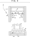
- FIGS. 7 to 9 show a state in which the film 4 conveyed inside the chamber 22 is raised and lowered according to the shape of the work to be coated 5.
- FIG. 9 shows the inside of the chamber 22 in the X direction of FIGS. 7 and 8 .
- the plurality of first elevating units 26 and the plurality of second elevating units 27 raise and lower the corresponding plurality of first gripping units 24 and plurality of second gripping units 25 according to the shape of the work to be coated 5.
- the plurality of first elevating units 26 and the plurality of second elevating units 27 each raise and lower a set of a first gripping unit 24 and a second gripping unit 25 arranged at positions opposing each other to the same height, among the plurality of first gripping units 24 and the plurality of second gripping units 25 aligned at positions opposing each other.
- each of the gripping units 24 and 25 grips the film 4. That is, each of the gripping units 24 and 25 is in a gripping state.
- an example has been described in which the plurality of first gripping units 24 and the plurality of second gripping units 25 are in an open state when being raised and lowered, and are thereafter in a gripping state, but there is no limitation to this.
- the plurality of first gripping units 24 and the plurality of second gripping units 25 are raised and lowered, some of the gripping units 24 and 25 among the plurality of first gripping units 24 and the plurality of second gripping units 25 may be gripping the film 4. Also, the plurality of first gripping units 24 and the plurality of second gripping units 25 may grip with a weaker gripping force compared to the gripping state.
- the heating units 29 are raised and lowered so as to maintain a certain distance in conjunction with the movement of the corresponding sets of the first gripping units 24 and the second gripping units 25. This allows the distance between the plurality of heating units 29 and the film 4 to be kept constant, and can prevent certain parts of the film 4 from being overheated or underheated when the later-described plurality of heating units 29 heat the film 4.
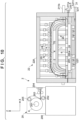
- FIG. 10 shows a state in which the upper chamber 220 is lowered after the heights of the first gripping units 24 and the second gripping units 25 in FIG. 7 are adjusted.
- FIG. 11 shows the inside of the chamber 22 in the X direction of FIG. 10 .
- the film 4 may be cut by the cutter 204, as shown in FIG. 10 , for example. Due to the upper chamber 220 being lowered to come into contact with the lower chamber 221, the inner space surrounded by the upper chamber 220 and the lower chamber 221 can be kept sealed.
- the pressure inside the chamber 22 is reduced by the air pressure adjustment unit 23 shown in FIG. 1 while the chamber 22 remains sealed.
- the plurality of first gripping units 24 and the plurality of second gripping units 25 are located at heights where the film 4 and the work to be coated 5 are separated from each other. This allows the pressure of the entire interior of the chamber 22 to be reduced.
- the film 4 is heated by the heating unit 29.
- the film 4 is softened by heating, and thus conformability to the work to be coated 5 can be improved.
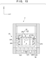
- FIG. 12 shows a state in which the plurality of first gripping units 24 and the plurality of second gripping units 25 are lowered.
- FIG. 13 shows the inside of the chamber 22 in the X direction of FIG. 12 .
- the plurality of first elevating units 26 lower the plurality of first gripping units 24.
- the plurality of second elevating units 27 lower the plurality of second gripping units 25.
- the film 4 and protrusions 70 provided on the jig 7 on which the work to be coated 5 is placed come into in contact with each other.
- the protrusions 70 are portions formed so as to protrude along the conveying direction of the film 4, and are provided on both sides of the work to be coated 5.
- the heights of the protrusions 70 are higher than the work to be coated 5 placed on the jig.
- the air pressure adjustment unit 23 shown in FIG. 1 increases the pressure inside of the chamber 22.
- the space sealed by the film 4 and the jig 7 shown in FIG. 13 remains in a reduced pressure state. Therefore, a pressure difference occurs between the space sealed by the film 4 and the jig 7 and the outer space outside of the sealed space. This difference causes the film 4 to coat the work to be coated 5.
- FIGS. 14 and 15 show a state in which the work to be coated 5 is coated with the film 4.
- FIG. 15 shows the inside of the chamber 22 in the X direction of FIG. 14 .
- the upper chamber 220 is raised.
- the leading end gripping portion 210 releases the film 4.
- the work to be coated 5 that has been coated with the film 4 is carried out of the chamber 22.
- each of the gripping units 24 and 25 of the plurality of first gripping units 24 and the plurality of second gripping units 25 is a pair of plate-shaped elastic members that sandwich the film 4, but there is no limitation to this.
- FIGS. 16A to 16D show examples of other configurations of each of the gripping units 24 and 25.
- FIG. 16A shows a schematic diagram of each of the gripping units 24 and 25 in the X direction.
- FIGS. 16B to 16D are schematic diagrams in the Y direction of FIG. 16A .
- gripping portions 240' of each of gripping units 24' and 25' may also be a pair of rotating members that sandwich the film 4.
- the pair of rotating members are members that rotate about an axis in the Y direction.
- the pair of rotating members in this embodiment may be supported by support members 241' including actuators, as shown in FIG. 16A .
- the pressure inside of the chamber 22 is reduced and then increased by the air pressure adjustment unit 23 to coat the work to be coated 5 with the film 4.
- the method for coating the work to be coated 5 with the film 4 is not limited to this.
- the work to be coated 5 may also be coated with the film 4 without being heated.
- the pressure in the lower chamber 221 may be reduced via the film 4 while the upper chamber 220 is maintained at atmospheric pressure, and the work to be coated 5 may be coated with the film 4 due to the pressure difference between the lower chamber 221 and the upper chamber 220.
- the work to be coated 5 may be coated with the film 4 without reducing the pressure inside the chamber 220.
- the work to be coated 5 may also be coated with the film 4 by pressurizing the film 4 with compressed air or the like from the side of the film 4 opposite to the side of the work to be coated 5.
- the film 4 may be pressed against the work to be coated 5 using a mold or the like to coat the work to be coated 5.
Landscapes
- Engineering & Computer Science (AREA)
- Manufacturing & Machinery (AREA)
- Physics & Mathematics (AREA)
- Thermal Sciences (AREA)
- Coating Apparatus (AREA)
- Blow-Moulding Or Thermoforming Of Plastics Or The Like (AREA)
- Lining Or Joining Of Plastics Or The Like (AREA)
Applications Claiming Priority (1)
| Application Number | Priority Date | Filing Date | Title |
|---|---|---|---|
| JP2023100248A JP7550413B1 (ja) | 2023-06-19 | 2023-06-19 | 被覆装置 |
Publications (2)
| Publication Number | Publication Date |
|---|---|
| EP4480673A2 true EP4480673A2 (de) | 2024-12-25 |
| EP4480673A3 EP4480673A3 (de) | 2025-01-08 |
Family
ID=91581960
Family Applications (1)
| Application Number | Title | Priority Date | Filing Date |
|---|---|---|---|
| EP24182669.2A Pending EP4480673A3 (de) | 2023-06-19 | 2024-06-17 | Beschichtungsvorrichtung |
Country Status (4)
| Country | Link |
|---|---|
| US (1) | US12600120B2 (de) |
| EP (1) | EP4480673A3 (de) |
| JP (1) | JP7550413B1 (de) |
| CN (1) | CN119159794A (de) |
Citations (1)
| Publication number | Priority date | Publication date | Assignee | Title |
|---|---|---|---|---|
| JP2021062625A (ja) | 2015-05-19 | 2021-04-22 | 布施真空株式会社 | 被着体の表面保護方法 |
Family Cites Families (16)
| Publication number | Priority date | Publication date | Assignee | Title |
|---|---|---|---|---|
| JPH01210328A (ja) * | 1988-02-19 | 1989-08-23 | Honda Motor Co Ltd | 真空ラミネート装置におけるフィルムの位置決め方法及び装置 |
| FR2657046B1 (fr) * | 1990-01-16 | 1992-04-30 | Saint Gobain Vitrage Int | Dispositif pour l'assemblage par pressage des vitrages feuilletes. |
| JP2797220B2 (ja) * | 1990-08-15 | 1998-09-17 | 本田技研工業株式会社 | 合成樹脂成形品の製造方法および製造装置 |
| JP2851205B2 (ja) * | 1992-03-31 | 1999-01-27 | 日本写真印刷 株式会社 | 成形同時絵付け用金型と成形同時絵付け方法 |
| JP3517889B2 (ja) * | 1993-02-04 | 2004-04-12 | 井関農機株式会社 | 樹脂板成型装置 |
| JP3639096B2 (ja) * | 1997-11-11 | 2005-04-13 | トヨタ自動車株式会社 | 真空成形方法及び真空成形装置 |
| JP3336246B2 (ja) * | 1998-02-20 | 2002-10-21 | 大日本印刷株式会社 | 射出成形同時絵付装置及び方法 |
| JP2002240099A (ja) * | 2001-02-16 | 2002-08-28 | Asano Laboratories Co Ltd | 成形装置、成形方法、シート枠および押さえ枠 |
| DE10201389A1 (de) | 2002-01-16 | 2003-07-24 | Seeber Ag & Co | Kaschiervorrichtung |
| DE10258891A1 (de) | 2002-12-17 | 2004-07-01 | Bayerische Motoren Werke Ag | Verfahren zum Bespannen eines flächigen Interieur-Bauteils |
| JP5201490B2 (ja) | 2008-12-24 | 2013-06-05 | 富士電機株式会社 | 可撓性基板の処理装置および薄膜積層体の製造装置 |
| US9970100B2 (en) * | 2012-11-16 | 2018-05-15 | The Boeing Company | Interlayer composite substrates |
| JP6384342B2 (ja) * | 2015-01-30 | 2018-09-05 | トヨタ車体株式会社 | フィルム被覆部品の製造装置及び製造方法 |
| JP6475129B2 (ja) * | 2015-09-16 | 2019-02-27 | 豊田合成株式会社 | 加飾成形品の製造方法 |
| DE102019000300A1 (de) | 2018-09-19 | 2020-03-19 | Kiefel Gmbh | Greifer für eine vorrichtung zum formen und/oder kaschieren eines folienelements, drapierrahmen, vorrichtung zum formen und/oder kaschieren eines folienelements, anlage zum fertigen eines formteils oder eines kaschierten bauteils, verfahren zum formen oder kaschieren eines folienelements sowie verfahren zum fertigen eines kaschierten bauteils |
| KR102759432B1 (ko) * | 2021-04-20 | 2025-01-24 | (주)유피티 | 표피재 부착장치 |
-
2023
- 2023-06-19 JP JP2023100248A patent/JP7550413B1/ja active Active
-
2024
- 2024-06-12 US US18/741,285 patent/US12600120B2/en active Active
- 2024-06-14 CN CN202410767391.3A patent/CN119159794A/zh active Pending
- 2024-06-17 EP EP24182669.2A patent/EP4480673A3/de active Pending
Patent Citations (1)
| Publication number | Priority date | Publication date | Assignee | Title |
|---|---|---|---|---|
| JP2021062625A (ja) | 2015-05-19 | 2021-04-22 | 布施真空株式会社 | 被着体の表面保護方法 |
Also Published As
| Publication number | Publication date |
|---|---|
| US20240416641A1 (en) | 2024-12-19 |
| CN119159794A (zh) | 2024-12-20 |
| US12600120B2 (en) | 2026-04-14 |
| EP4480673A3 (de) | 2025-01-08 |
| JP7550413B1 (ja) | 2024-09-13 |
| JP2025000407A (ja) | 2025-01-07 |
Similar Documents
| Publication | Publication Date | Title |
|---|---|---|
| JP6402070B2 (ja) | 材料の層状体の表面輪郭を規定するためのシステム及び方法 | |
| US11173648B2 (en) | Thermoforming device and thermoforming method | |
| KR101421396B1 (ko) | 몰드 박리 장치 | |
| KR101290613B1 (ko) | 성형 장치 및 성형 방법 | |
| CN105142881A (zh) | 薄膜压印设备 | |
| EP4480673A2 (de) | Beschichtungsvorrichtung | |
| US20220212423A1 (en) | Drape forming apparatus and device, and method of forming a composite structure | |
| US12162205B2 (en) | Gripper for a draping frame and for a device, draping frame, device and method for the forming of and/or covering using a film element, system for manufacturing a moulded part or a covered component, method for retro-fitting a device of this type, method for manufacturing a covered component | |
| EP4480675A1 (de) | Spannvorrichtung und beschichtungsvorrichtung | |
| CN102189678B (zh) | 农业用聚烯烃类树脂薄膜的制造方法及制造装置 | |
| FI112042B (fi) | Menetelmä ja laitteisto kolmiulotteisten muotojen muovaamiseksi ohutlevyyn | |
| CN114669445A (zh) | 一种微纳米结构涂层的柔性辊压成形装置 | |
| JP2016198940A (ja) | インモールド加飾成形方法およびインモールド加飾成形装置 | |
| US20250353240A1 (en) | Coating apparatus | |
| US20250353239A1 (en) | Coating apparatus | |
| JP7549848B1 (ja) | 被覆装置 | |
| EP4008531B1 (de) | Herstellungsvorrichtung, verfahren und system | |
| US20250361031A1 (en) | Stringer handling and forming tool | |
| EP4538010A1 (de) | Pick-and-place-endeffektor mit konfiguration zur bildung eines knicks | |
| KR20100014620A (ko) | 필름에 점착된 장식부를 물체에 부착하는 장치 및 방법 | |
| JPH0546292B2 (de) | ||
| WO2024124361A1 (en) | Apparatus and methods for forming curved films | |
| KR20240162509A (ko) | 적층 성형 시스템 및 적층 성형 방법 | |
| CN119305229A (zh) | 具有成品经涂覆表面的碳纤维压缩成型零件 | |
| CN118103314A (zh) | 在用于处理或加工毛皮的生产线中的毛皮进给设备 |
Legal Events
| Date | Code | Title | Description |
|---|---|---|---|
| PUAI | Public reference made under article 153(3) epc to a published international application that has entered the european phase |
Free format text: ORIGINAL CODE: 0009012 |
|
| STAA | Information on the status of an ep patent application or granted ep patent |
Free format text: STATUS: REQUEST FOR EXAMINATION WAS MADE |
|
| PUAL | Search report despatched |
Free format text: ORIGINAL CODE: 0009013 |
|
| 17P | Request for examination filed |
Effective date: 20240617 |
|
| AK | Designated contracting states |
Kind code of ref document: A2 Designated state(s): AL AT BE BG CH CY CZ DE DK EE ES FI FR GB GR HR HU IE IS IT LI LT LU LV MC ME MK MT NL NO PL PT RO RS SE SI SK SM TR |
|
| AK | Designated contracting states |
Kind code of ref document: A3 Designated state(s): AL AT BE BG CH CY CZ DE DK EE ES FI FR GB GR HR HU IE IS IT LI LT LU LV MC ME MK MT NL NO PL PT RO RS SE SI SK SM TR |
|
| RIC1 | Information provided on ipc code assigned before grant |
Ipc: B29C 63/02 20060101AFI20241204BHEP |