EP4477972A1 - Kühlmittelfüllverfahren - Google Patents
Kühlmittelfüllverfahren Download PDFInfo
- Publication number
- EP4477972A1 EP4477972A1 EP23778825.2A EP23778825A EP4477972A1 EP 4477972 A1 EP4477972 A1 EP 4477972A1 EP 23778825 A EP23778825 A EP 23778825A EP 4477972 A1 EP4477972 A1 EP 4477972A1
- Authority
- EP
- European Patent Office
- Prior art keywords
- refrigerant
- container
- boiling point
- port
- refrigeration circuit
- Prior art date
- Legal status (The legal status is an assumption and is not a legal conclusion. Google has not performed a legal analysis and makes no representation as to the accuracy of the status listed.)
- Granted
Links
Images


Classifications
-
- F—MECHANICAL ENGINEERING; LIGHTING; HEATING; WEAPONS; BLASTING
- F25—REFRIGERATION OR COOLING; COMBINED HEATING AND REFRIGERATION SYSTEMS; HEAT PUMP SYSTEMS; MANUFACTURE OR STORAGE OF ICE; LIQUEFACTION SOLIDIFICATION OF GASES
- F25B—REFRIGERATION MACHINES, PLANTS OR SYSTEMS; COMBINED HEATING AND REFRIGERATION SYSTEMS; HEAT PUMP SYSTEMS
- F25B45/00—Arrangements for charging or discharging refrigerant
-
- F—MECHANICAL ENGINEERING; LIGHTING; HEATING; WEAPONS; BLASTING
- F25—REFRIGERATION OR COOLING; COMBINED HEATING AND REFRIGERATION SYSTEMS; HEAT PUMP SYSTEMS; MANUFACTURE OR STORAGE OF ICE; LIQUEFACTION SOLIDIFICATION OF GASES
- F25B—REFRIGERATION MACHINES, PLANTS OR SYSTEMS; COMBINED HEATING AND REFRIGERATION SYSTEMS; HEAT PUMP SYSTEMS
- F25B2345/00—Details for charging or discharging refrigerants; Service stations therefor
- F25B2345/001—Charging refrigerant to a cycle
-
- F—MECHANICAL ENGINEERING; LIGHTING; HEATING; WEAPONS; BLASTING
- F25—REFRIGERATION OR COOLING; COMBINED HEATING AND REFRIGERATION SYSTEMS; HEAT PUMP SYSTEMS; MANUFACTURE OR STORAGE OF ICE; LIQUEFACTION SOLIDIFICATION OF GASES
- F25B—REFRIGERATION MACHINES, PLANTS OR SYSTEMS; COMBINED HEATING AND REFRIGERATION SYSTEMS; HEAT PUMP SYSTEMS
- F25B2400/00—Component parts or details not otherwise provided for in this subclass
- F25B2400/12—Inflammable refrigerants
Definitions
- the present invention relates to a method for charging a refrigerant (refrigerant charging method).
- Patent Literature (hereinafter, referred to as PTL) 1 discloses a method for filling a refrigerant circuit with a non-azeotropic refrigerant mixture by using a tank that contains the non-azeotropic refrigerant mixture at an amount that can be filled at one time.
- the refrigerant circuit is applied to an air conditioner, and R407C is used as the non-azeotropic refrigerant mixture.
- R407C is composed of HFC32 (boiling point: -51.7°C), HFC125 (boiling point: - 48.5°C), and HFC134a (boiling point: -26.5°C).
- the boiling points of these three refrigerants are relatively close to each other. Therefore, these three types of refrigerants are considered to be mixed relatively evenly in the tank at room temperature before being charged into the refrigerant circuit.
- some non-azeotropic refrigerant mixtures are composed of a plurality of refrigerants having boiling points significantly different to each other, such as a non-azeotropic refrigerant mixture that is configured to fill a refrigeration circuit of an ultra-low temperature freezer that achieves an extremely low temperature of -80°C or less.
- These plurality of refrigerants may be in a state such that the refrigerants are separated from each another in a sealed container before being charged into the refrigeration circuit.
- An object of the present disclosure is to provide a refrigerant charging method capable of reliably charging a non-azeotropic refrigerant mixture into a refrigeration circuit.
- a refrigerant charging method is: a method for charging a refrigerant into a refrigeration circuit that includes a compressor, a condenser, a throttle device, an evaporator, and a first port, the first port being disposed in a high pressure portion of the compressor or in a location downstream of the compressor and upstream of the throttle device, the method including:
- the present disclosure can provide a refrigerant charging method capable of reliably charging a non-azeotropic refrigerant mixture into a refrigeration circuit.
- FIG. 1 illustrates an overview of refrigeration circuit 100 according to an embodiment of the present disclosure.
- Refrigeration circuit 100 is applied to a refrigeration apparatus such as an ultra-low temperature freezer.
- Refrigeration circuit 100 includes compressor 1, condenser 2, gas-liquid separator 3, first heat exchanger 4, auxiliary throttle device 5, throttle device 6, second heat exchanger 7, and evaporator 8. Refrigeration circuit 100 may further include refrigerant tank 9 and throttle device 10 for connecting the refrigerant tank (herein also referred to as "refrigerant tank connecting throttle device").
- the refrigerant flowing through refrigeration circuit 100 is a non-azeotropic refrigerant mixture, which is a mixture of refrigerants having boiling points different to each other.
- the non-azeotropic refrigerant mixture contains a high boiling point refrigerant, a medium boiling point refrigerant having a boiling point lower than that of the high boiling point refrigerant, and a low boiling point refrigerant having a boiling point lower than that of the medium boiling point refrigerant.
- the non-azeotropic refrigerant mixture may be simply referred to as a refrigerant.
- Compressor 1 compresses a sucked refrigerant and discharges the refrigerant into a pipe.
- the discharged refrigerant flows into condenser 2 through the pipe.
- Compressor 1 includes a low pressure portion (containing the refrigerant before being compressed) between a suction port that sucks in the refrigerant and a region that compresses the refrigerant (for example, a cylinder), and a high pressure portion (containing the refrigerant after being compressed) between the region compressing the refrigerant and a discharge port that discharges the compressed refrigerant.
- Condenser 2 is a heat exchanger equipped with a fan that is rotated by a fan motor. Condenser 2 is a heat exchanger that cools a refrigerant by exchanging heat with the surrounding air sent in by the fan, and condenses at least a portion of the refrigerant. The refrigerant that has passed through condenser 2 flows into gas-liquid separator 3.
- Gas-liquid separator 3 is a container that separates the refrigerant into gas and liquid.
- a refrigerant in a gas state namely a component (component with a relatively low boiling point) which is not condensed in condenser 2 flows out from gas-liquid separator 3 in the gas state and into inner tube 4a of first heat exchanger 4.
- a refrigerant in a liquid state namely a component (component with a relatively high boiling point) which is condensed in condenser 2, flows out from gas-liquid separator 3 and into auxiliary throttle device 5.
- Auxiliary throttle device 5 is, for example, a capillary tube. When passing through auxiliary throttle device 5, the refrigerant is throttled and expanded to lower the pressure and temperature of the refrigerant. The refrigerant flowing out from auxiliary throttle device 5 flows into outer tube 4b of first heat exchanger 4.
- First heat exchanger 4 is a heat exchanger including inner tube 4a and outer tube 4b surrounding inner tube 4a.
- a refrigerant flowing through inner tube 4a exchanges heat with a refrigerant flowing through outer tube 4b, and loses heat.
- Throttle device 6 is, for example, a capillary tube. When passing through throttle device 6, the refrigerant is throttled and expanded to lower the pressure and temperature of the refrigerant.
- throttle device 6 constitutes second heat exchanger 7 together with outer tube 7b of second heat exchanger 7. Throttle device 6 is surrounded by outer tube 7b. Therefore, a refrigerant passing through throttle device 6 exchanges heat with a refrigerant passing through outer tube 7b to lose heat, becoming even lower in temperature.
- the refrigerant flowing out from throttle device 6 flows into evaporator 8 and evaporates. At this time, the surrounding of evaporator 8, that is, the object to be cooled, is cooled.
- the refrigerant flowing out from evaporator 8 flows into outer tube 7b of second heat exchanger 7, absorbs heat from a refrigerant flowing through throttle device 6, and flows out from outer tube 7b.
- the refrigerant flowing out from outer tube 7b flows into outer tube 4b of first heat exchanger 4, and joins to mix with a refrigerant flowing out from auxiliary throttle device 5.
- the mixed refrigerant absorbs heat from a refrigerant flowing through inner tube 4a of first heat exchanger 4, evaporates completely, and flows out from outer tube 4b.
- the refrigerant flowing out from outer tube 4b is sucked into compressor 1, compressed again, and discharged.
- Refrigerant tank 9 may be connected via refrigerant tank connecting throttle device 10 to a pipe located downstream of outer tube 4b and upstream of compressor 1.
- Refrigeration circuit 100 configured as described above is divided, with compressor 1 and throttle device 6 as boundaries, into a high pressure circuit with a high pressure refrigerant therein, and a low pressure circuit with a low pressure refrigerant therein.
- the high pressure circuit includes the high pressure portion of compressor 1 and a portion located downstream of compressor 1 and upstream of throttle device 6.
- the high pressure circuit also includes a portion between gas-liquid separator 3 and auxiliary throttle device 5.
- the low pressure circuit includes the low pressure portion of compressor 1 and a portion located upstream of compressor 1 and downstream of throttle device 6.
- the low pressure circuit also includes refrigerant tank 9 and refrigerant tank connecting throttle device 10.
- First port 11 is disposed at the high pressure circuit.
- Second port 12 is disposed at the low pressure circuit.
- First port 11 is provided, for example, at a pipe located downstream of condenser 2 and upstream of gas-liquid separator 3 as illustrated in FIG. 1 .
- Second ports 12 are provided, for example, at the low pressure portion of compressor 1 and at refrigerant tank 9 as illustrated in FIG. 1 . These ports are normally closed and are connected to a refrigerant supply source for charging a refrigerant into refrigeration circuit 100 for the first time or for charging a refrigerant for refilling. The refrigerant is charged into refrigeration circuit 100 from the refrigerant supply source through each port.
- the numbers of first ports 11 and second ports 12 are not limited to that illustrated in the drawing.
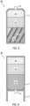
- FIG. 2 is a schematic cross-sectional view of container 20 (filled with a refrigerant) which is a refrigerant supply source.
- Container 20 includes container main body 21 and mouth 22.
- Container main body 21 includes a cylindrical side wall, and a bottom and a ceiling part that close both ends of the side wall. Mouth 22 is provided at the ceiling part.
- Container 20 is, for example, a tank.
- Container 20 does not include a siphon tube, and therefore container 20 can be easily produced.
- Container 20 may include a short siphon tube that does not reach the bottom of container 20.
- a side hole may be formed near the base (end part of the siphon tube on the ceiling part side) of the siphon tube. Forming a side hole allows high boiling point refrigerant 23 in a liquid form to be discharged from container 20 through the siphon tube when container 20 is placed in a position such that mouth 22 faces downward as described below.
- Container 20 has a shape that allows the container to be stably placed on a horizontal surface with the bottom part of container main body 21 at a lower location and the ceiling part, namely mouth 22, at a higher location. In other words, container 20 can stand on a horizontal surface.
- FIG. 2 illustrates container 20 with mouth 22 facing upward (that is, container 20 is in an upright position).
- Container 20 may have any shape as long as the container includes mouth 22.
- Container 20 contains enclosed therein a non-azeotropic refrigerant mixture including high boiling point refrigerant 23, medium boiling point refrigerant 24 having a boiling point lower than that of high boiling point refrigerant 23, and low boiling point refrigerant 25 having a boiling point lower than that of the medium boiling point refrigerant.
- high boiling point refrigerant 23 is in a liquid state
- medium boiling point refrigerant 24 is in a wet gas state
- low boiling point refrigerant 25 is in a gas state inside container 20. Therefore, the three refrigerants are in a substantially separated state in container 20.
- high boiling point refrigerant 23 in a liquid state is located near the bottom of container main body 21
- low boiling point refrigerant 25 in a gas state is located near mouth 22
- medium boiling point refrigerant 24 in a wet gas state is located between high boiling point refrigerant 23 and low boiling point refrigerant 25.
- high boiling point refrigerant 23 in a liquid state is located near mouth 22
- low boiling point refrigerant 25 in a gas state is located near the bottom of container main body 21
- medium boiling point refrigerant 24 in a wet gas state is located between high boiling point refrigerant 23 and low boiling point refrigerant 25, as illustrated in FIG. 3 .
- High boiling point refrigerant 23, medium boiling point refrigerant 24, and low boiling point refrigerant 25 may be any refrigerants as long as the refrigerants are respectively in a liquid state, a wet gas state, and a gas state in container 20 placed in a room temperature environment.
- high boiling point refrigerant 23 is normal butane
- medium boiling point refrigerant 24 is ethane
- low boiling point refrigerant 25 is methane.
- High boiling point refrigerant 23 may be normal butane or isobutane
- medium boiling point refrigerant 24 may be ethane, ethylene, or xenon
- low boiling point refrigerant 25 may be methane or krypton.
- the total weight of the non-azeotropic refrigerant mixture may be 150 g or less. By keeping the total weight below 150g, it is possible to comply with International Electrotechnical Commission (IEC) standards. Furthermore, a hydrocarbon gas and a rare gas can reduce the environmental load.
- IEC International Electrotechnical Commission
- the ratio of refrigerants enclosed in container 20 is such that, for example, high boiling point refrigerant 23 is 50 wt% or more and 80 wt% or less, medium boiling point refrigerant 24 is 10 wt% or more and less than 50 wt%, and low boiling point refrigerant 25 is 20 wt% or less, with the total of the contents of container 20 (namely, non-azeotropic refrigerant mixture) being 100 wt%.
- the total amount of medium boiling point refrigerant 24 and low boiling point refrigerant 25 is 50 mass% or less.
- the low boiling refrigerant may be entirely replaced with a medium boiling refrigerant.
- a refrigerant is charged from container 20, which is a refrigerant supply source, into refrigeration circuit 100 as follows.
- the charging of the refrigerant is performed before refrigeration circuit 100 starts operating, or when a refrigerant leak occurs after refrigeration circuit 100 starts operating.
- the charging is performed when a state, in which a lubricating oil for lubricating compressor 1 tends to accumulate in evaporator 8, continues for a certain period of time (for example, after a power failure occurs when the temperature is low and the system is left unattended for a while), and further when a refrigerant leaks.
- first port 11 is connected with mouth 22 via a valve and a pipe.
- Container 20 may include a valve attached to mouth 22. At substantially the same time, container 20 is placed in the position illustrated in FIG. 3 , that is, in a position such that mouth 22 faces downward.
- the valve is then opened. Before the valve is opened, the pressure inside the refrigeration circuit 100 may be reduced. The pressure can be reduced by, for example, sucking from the inside of refrigeration circuit 100 with a vacuum pump through at least one of first port 11 and second port 12.
- the refrigerant enclosed in container 20 is charged into refrigeration circuit 100 through first port 11.
- high boiling point refrigerant 23 located near mouth 22 is charged first, then the medium boiling point refrigerant is charged, and finally the low boiling point refrigerant is charged.
- the force pushing high boiling point refrigerant 23 having entered throttle device 6 and auxiliary throttle device 5, which have a large piping resistance, toward the low pressure circuit is provided by medium boiling point refrigerant 24 and low boiling point refrigerant 25 in container 20.
- medium boiling point refrigerant 24 and low boiling point refrigerant 25 have lower boiling points than high boiling point refrigerant 23 and thus would have higher pressures than high boiling point refrigerant 23 when the refrigerants are in the same temperature environment.
- high boiling point refrigerant 23, which has permeated through the high pressure circuit is pushed by medium boiling point refrigerant 24 and low boiling point refrigerant 25 in container 20, enters throttle device 6 and auxiliary throttle device 5 and passes through throttle device 6 and auxiliary throttle device 5.
- medium boiling point refrigerant 24 and low boiling point refrigerant 25 can then enter the high pressure circuit.
- a step may be performed as follows.
- the low pressure circuit provided with second port 12 is located downstream of throttle device 6 and auxiliary throttle device 5, which have large piping resistance, as viewed from first port 11. Due to the structure, even when high boiling point refrigerant 23 is charged into the high pressure circuit upstream of throttle device 6 and auxiliary throttle device 5, high boiling point refrigerant 23 cannot immediately flow into the low pressure circuit. That is, the low pressure state of the low pressure circuit continues for at least a certain period of time after the start of refrigerant charging.
- the refrigerant remaining in container 20 can no longer enter refrigeration circuit 100 (specifically, the high pressure circuit) from first port 11, the low boiling point refrigerant and the medium boiling point refrigerant remaining in container 20 can be introduced into the refrigerant circuit (specifically, the low pressure circuit) from second port 12.
- refrigeration circuit 100 specifically, the high pressure circuit
- the low boiling point refrigerant and the medium boiling point refrigerant remaining in container 20 can be introduced into the refrigerant circuit (specifically, the low pressure circuit) from second port 12.
- the position of the container 20 may be such that the mouth 22 faces upward or downward, and in either case, the entire amount of the refrigeration remaining in container 20 can be reliably charged to refrigeration circuit 100.
- refrigeration circuit 100 does not need to include second port 12.
- the refrigerant inlet can be switched from first port 11 to second port 12 by disconnecting container 20 from first port 11 and then connecting container 20 to second port 12 via a pipe and a valve.
- a below described jig 30 may also be used.
- FIG. 4 schematically illustrates jig 30.
- Jig 30 includes container connection port 31, branch pipe 32, two port connection ports 33, and two valves 34.
- the two valves 34 constitute a path switching device.
- Container connection port 31 is a connection part that is connected to mouth 22 of container 20.
- Branch pipe 32 is composed of pipes having a shape such that one pipe branches into two pipes, and container connection port 31 is attached to the end part of the one pipe before the branching.
- port connection port 33 is attached to each of the end parts of the two pipes of branch pipe 32 after the branching.
- Port connection port 33 is a connection part that is connected to first port 11 or second port 12.
- Valve 34 is attached to each of the two pipes of branch pipe 32 after the branching.
- a refrigerant is charged from container 20 to refrigeration circuit 100 as follows. First, the two valves 34 are closed. Mouth 22 of container 20 is connected to container connection port 31, one of port connection ports 33 is connected to first port 11, and the other one of port connection ports 33 is connected to second port 12. At substantially the same time as these connections, container 20 is placed in a position with mouth 22 facing downward.
- Valve 34 attached to the pipe connected to first port 11 is then opened-the pipe being one of the two pipes of branch pipe 32 after the branching.
- a refrigerant enclosed in container 20 is then charged into refrigeration circuit 100 through first port 11.
- high boiling point refrigerant 23 located near mouth 22 is charged first.
- valve 34 attached to the pipe connected to first port 11 is closed, and then valve 34 attached to the pipe connected to second port 12 is opened. That is, the refrigerant paths are switched by the path switching device. The refrigerant remaining in container 20 is then charged into refrigerant circuit from second port 12.
- the switching between opening and closing of valves 34 may be performed as follows: while the weight of container 20 is measured, and when the weight reaches a predetermined value, or when a pressure gauge attached to refrigeration circuit 100, jig 30, or container 20 indicates a predetermined pressure, the opening and closing are switched.
- jig 30 can easily change the location at which the refrigerant is charged from container 20 to refrigeration circuit 100, thereby reliably charging the refrigerant in container 20 into refrigeration circuit 100.
- mouth 22 of container 20 may be connected to second port 12 in place of first port 11, and the refrigerant may be charged into refrigeration circuit 100 through second port 12 from the beginning.
- container 20 is placed in a position such that mouth 22 faces upward (i.e., in an upright position). That is, low boiling point refrigerant 25 located near the top of container 20 is charged first into refrigeration circuit 100 (specifically, into the low pressure circuit). Medium boiling point refrigerant 24 is then charged into refrigeration circuit 100.
- high boiling point refrigerant 23 in a liquid state is located at the bottom of container 20 and cannot enter refrigeration circuit 100.
- low boiling point refrigerant 25 and medium boiling point refrigerant 24 are charged into refrigeration circuit 100 through second port 12, the position of container 20 is thus changed so that mouth 22 faces downward.
- the high boiling point refrigerant 23 in container 20 is then charged into refrigeration circuit 100 through second port 12.
- Low boiling point refrigerant 25 and medium boiling point refrigerant 24 have small molecular weights and can pass through throttle device 6 and auxiliary throttle device 5 relatively easily. Therefore, low boiling point refrigerant 25 and medium boiling point refrigerant 24 charged into the low pressure circuit from second port 12 can pass through throttle device 6 and auxiliary throttle device 5 and flow into the high pressure circuit. In addition, the total ratio of medium boiling point refrigerant 24 and low boiling point refrigerant 25 to the total weight of the refrigerants enclosed in container 20 is 50 mass% or less. Further, the low pressure circuit includes members with a relatively large volume (that is, evaporator 8, outer tube 4b of first heat exchanger 4, outer tube 7b of second heat exchanger 7, and refrigerant tank 9).
- lubricating oil for lubricating compressor 1 may be retained in a low-temperature and large-volume portion, such as evaporator 8, while the temperature of the lubricating oil has dropped and the viscosity of the lubricating oil has increased.
- a hydrocarbon for example, ethane
- medium boiling point refrigerant 24 which is highly compatible with the lubricating oil for lubricating compressor 1
- the viscosity of the lubricating oil can be reduced.
- refrigeration circuit 100 is in a state such that high boiling point refrigerant 23 is located in the low pressure circuit, and low boiling point refrigerant 25 and medium boiling point refrigerant 24 are located in the high pressure circuit.
- the refrigerant that is sucked in and compressed is mainly high boiling point refrigerant 23.
- High boiling point refrigerant 23 has a higher boiling point than low boiling point refrigerant 25 and medium boiling point refrigerant 24; therefore, high boiling point refrigerant 23 would have a lower pressure than low boiling point refrigerant 25 and medium boiling point refrigerant 24 when the refrigerants are in the same temperature environment.
- the discharge pressure of compressor 1 does not become high at the time of starting of the compressor, and therefore compressor 1 can be easily started up at a relatively low load.
- the port to which container 20 is first connected may be first port 11 or second port 12.
- the port to be used first for the refrigerant charging from container 20 can be determined by detecting the state of refrigeration circuit 100 or a refrigeration apparatus including refrigeration circuit 100 and based on the detected state.
- the state of refrigeration circuit 100 or a refrigeration apparatus including refrigeration circuit 100 is detected, and based on the detected state, mouth 22 is connected to second port 12 in place of first port 11.
- mouth 22 is connected to second port 12 in place of first port 11.
- at least a portion of the refrigerant in container 20 is charged into refrigeration circuit 100 through second port 12 from container 20 in a position such that mouth 22 faces upward.
- the position of container 20 is changed so that mouth 22 faces downward, and the refrigerant remaining in container 20 is charged.
- the state of refrigeration circuit 100 or a refrigeration apparatus including refrigeration circuit 100 is detected by a temperature sensor attached to refrigeration circuit 100 or the refrigeration apparatus before the refrigerant is charged and when refrigeration circuit 100 is operating.
- An exemplary relationship between the installation location of the temperature sensor, the detection result from the temperature sensor, and the port through which a refrigerant is charged is as shown in Table 1.
- a temperature sensor that detects the temperature inside the storage is used in addition to the temperature sensors shown in Table 1 for determination.
- a case where refrigeration circuit 100 is applied to a cold storage such as an ultra-low temperature freezer will be described.
- the refrigerant temperature at the outlet of condenser 2 is higher than a predetermined value and the temperature inside the storage is higher than a predetermined value-that is when the detection results of the temperature sensor at the outlet of condenser 2 and the temperature sensor for measuring the temperature inside the storage indicate abnormally high temperatures, the following abnormality may have occurred. That is, there is a possibility that clogging due to lubricating oil or impurities, which may cause poor condensation in inner tube 4a of first heat exchanger 4, has occurred. That is, there is a possibility that an abnormality has occurred in the high pressure circuit (particularly in inner tube 4a of the first heat exchanger).
- first port 11 is used for the refrigerant charging. Charging a refrigerant through first port 11 can eliminate the above-described problem.
- first port 11 is used for the refrigerant charging. Charging a refrigerant through first port 11 can eliminate the above-described problem.
- second port 12 is used for the refrigerant charging. Charging a refrigerant through second port 12 can eliminate the above-described problem.
- first port 11 is used for the refrigerant charging. Charging a refrigerant through first port 11 can eliminate the above-described problem.
- second port 12 is used for the refrigerant charging. Charging a refrigerant through second port 12 can eliminate the above-described problem.
- mouth 22 of container 20 is connected to first port 11 to charge a refrigerant.
- mouth 22 of container 20 is connected to second port 12 to charge a refrigerant.
- the mouth is connected to second port 12.
- the detection results of the temperature sensors are recorded as a log in the control device of the refrigeration apparatus.
- the control device may determine the port through which a refrigerant is charged based on the log, and display the result of the determination on a display device provided in the refrigeration apparatus. An operator can view this display and charge a refrigerant through the appropriate port.
- container 20 may contain enclosed therein oil carrier agent 26 that is charged into refrigeration circuit 100 together with a non-azeotropic refrigerant mixture.
- oil carrier agent 26 may be, for example, normal pentane or propane.
- the oil carrier agent is in a liquid form in container 20 in a room temperature environment.
- the oil carrier agent is in a liquid state and thus mixes with high boiling point refrigerant 23 in a liquid form. Therefore, when container 20 is in a position such that mouth 22 faces downward, the oil carrier agent is charged into refrigeration circuit 100 together with high boiling point refrigerant 23 in a liquid form. Therefore, by connecting mouth 22 of container 20 to second port 12 and charging a refrigerant through the second port, the oil carrier agent can first be brought into contact with a refrigerant retained in the low pressure circuit. This configuration thus allows the retained refrigerant to quickly permeate through refrigeration circuit 100. Furthermore, using container 20 in which an oil carrier agent is enclosed in addition to a non-azeotropic refrigerant mixture can charge the oil carrier agent into refrigeration circuit 100 during the refrigerant charging step without performing a special step for charging the oil carrier agent.
- Compressor 1 may be a compressor that does not require lubricating oil.
- first, high boiling point refrigerant 23 is charged from first port 11, and then low boiling point refrigerant 25 and medium boiling point refrigerant 24 are charged from second port 12.
- the low pressure circuit has a relatively large volume, and thus the pressure rise in the low pressure circuit can be suppressed to some extent.
- the high pressure circuit has a relatively small volume, and thus high boiling point refrigerant 23 flows from the high pressure circuit into the low pressure circuit through throttle device 6 and auxiliary throttle device 5. That is, the pressure rise in the high pressure circuit is suppressed to some extent. Therefore, the discharge pressure of compressor 1 does not become high at the time of starting of the compressor, and thus compressor 1 can be easily started up at a relatively low load even without lubricating oil.
- Container 20 may include skirt 27, as illustrated in FIG. 6 .
- skirt 27 allows container 20 to stably stand on its own horizontally even when mouth 22 faces downward.
- a similar mouth 22 may be formed at a location (at a region corresponding to the bottom of container in FIG. 6 ) symmetrical to mouth 22.
- Providing skirt 27 can improve the workability of the refrigerant charging into refrigeration circuit 100.
- the path switching device provided in jig 30 may be configured with one three-way valve in place of the two valves 34.
- the refrigeration apparatus may include two refrigeration circuits 100.
- low boiling point refrigerant 23 does not have to be enclosed in container 20, and only medium boiling point refrigerant 24 and high boiling point refrigerant 25 may be enclosed as refrigerants constituting a non-azeotropic refrigerant mixture.
- the present disclosure is applicable to various refrigeration apparatuses (such as ultra-low temperature storages, ultra-low temperature freezers, medicine refrigerators, blood refrigerators, and incubators) each using a non-azeotropic refrigerant mixture as the refrigerant thereof.
- refrigeration apparatuses used in environments without gravity such as zero gravity or microgravity (for example, a space environment)
- the present disclosure can be applied to a refrigeration apparatus equipped with such a compressor, and can be extremely effectively utilized industrially.
Landscapes
- Engineering & Computer Science (AREA)
- Physics & Mathematics (AREA)
- Mechanical Engineering (AREA)
- Thermal Sciences (AREA)
- General Engineering & Computer Science (AREA)
- Compression-Type Refrigeration Machines With Reversible Cycles (AREA)
Applications Claiming Priority (2)
| Application Number | Priority Date | Filing Date | Title |
|---|---|---|---|
| JP2022054135 | 2022-03-29 | ||
| PCT/JP2023/003193 WO2023188789A1 (ja) | 2022-03-29 | 2023-02-01 | 冷媒チャージ方法 |
Publications (3)
| Publication Number | Publication Date |
|---|---|
| EP4477972A1 true EP4477972A1 (de) | 2024-12-18 |
| EP4477972A4 EP4477972A4 (de) | 2025-06-25 |
| EP4477972B1 EP4477972B1 (de) | 2026-05-06 |
Family
ID=88200828
Family Applications (1)
| Application Number | Title | Priority Date | Filing Date |
|---|---|---|---|
| EP23778825.2A Active EP4477972B1 (de) | 2022-03-29 | 2023-02-01 | Kühlmittelfüllverfahren |
Country Status (5)
| Country | Link |
|---|---|
| US (1) | US20250012496A1 (de) |
| EP (1) | EP4477972B1 (de) |
| JP (1) | JP7671919B2 (de) |
| CN (1) | CN118891482A (de) |
| WO (1) | WO2023188789A1 (de) |
Families Citing this family (1)
| Publication number | Priority date | Publication date | Assignee | Title |
|---|---|---|---|---|
| JP7813943B1 (ja) * | 2024-09-30 | 2026-02-13 | ダイキン工業株式会社 | 充填方法 |
Family Cites Families (15)
| Publication number | Priority date | Publication date | Assignee | Title |
|---|---|---|---|---|
| US3785163A (en) * | 1971-09-13 | 1974-01-15 | Watsco Inc | Refrigerant charging means and method |
| JPH06101940A (ja) * | 1992-09-22 | 1994-04-12 | Nippondenso Co Ltd | 冷媒封入方法 |
| JPH08193762A (ja) * | 1995-01-17 | 1996-07-30 | Matsushita Electric Ind Co Ltd | 非共沸混合冷媒用高圧容器 |
| JPH08200897A (ja) | 1995-01-30 | 1996-08-06 | Sanyo Electric Co Ltd | 非共沸混合冷媒充填装置 |
| JPH08313081A (ja) * | 1995-05-16 | 1996-11-29 | Hitachi Ltd | 冷媒封入用容器 |
| JPH09329375A (ja) * | 1996-06-10 | 1997-12-22 | Sanyo Electric Co Ltd | 非共沸混合冷媒の補充填方法およびその装置 |
| JP3287260B2 (ja) * | 1997-04-07 | 2002-06-04 | ダイキン工業株式会社 | 冷凍装置及びその冷媒充填方法 |
| JPH11270933A (ja) * | 1998-03-24 | 1999-10-05 | Sanyo Electric Co Ltd | 非共沸混合冷媒の充填方法、冷凍装置及び空気調和装置 |
| US5975151A (en) * | 1998-08-06 | 1999-11-02 | Ipg Corporation | Charging a refrigerator with non-volatile liquid |
| JP2009102567A (ja) | 2007-10-25 | 2009-05-14 | Kanou Reiki:Kk | 超低温用非共沸冷媒 |
| JP4906792B2 (ja) * | 2008-06-19 | 2012-03-28 | 三菱電機株式会社 | 蒸気圧縮式ヒートポンプ装置 |
| CN204438583U (zh) * | 2014-12-31 | 2015-07-01 | 华南理工大学 | 一种双机快速降温低温制冷系统 |
| JP6912649B2 (ja) * | 2018-02-20 | 2021-08-04 | Phcホールディングス株式会社 | 冷凍装置 |
| US11566820B2 (en) * | 2018-11-07 | 2023-01-31 | Shinwa Controls Co., Ltd. | Fluid temperature control system |
| JP7503837B2 (ja) | 2020-09-25 | 2024-06-21 | 新光化成株式会社 | 透視性釣具用ケース |
-
2023
- 2023-02-01 EP EP23778825.2A patent/EP4477972B1/de active Active
- 2023-02-01 CN CN202380027850.8A patent/CN118891482A/zh active Pending
- 2023-02-01 WO PCT/JP2023/003193 patent/WO2023188789A1/ja not_active Ceased
- 2023-02-01 JP JP2024511327A patent/JP7671919B2/ja active Active
-
2024
- 2024-09-25 US US18/895,993 patent/US20250012496A1/en active Pending
Also Published As
| Publication number | Publication date |
|---|---|
| JPWO2023188789A1 (de) | 2023-10-05 |
| EP4477972A4 (de) | 2025-06-25 |
| JP7671919B2 (ja) | 2025-05-02 |
| CN118891482A (zh) | 2024-11-01 |
| WO2023188789A1 (ja) | 2023-10-05 |
| EP4477972B1 (de) | 2026-05-06 |
| US20250012496A1 (en) | 2025-01-09 |
Similar Documents
| Publication | Publication Date | Title |
|---|---|---|
| CN102575886B (zh) | 制冷剂蒸气压缩系统的运行 | |
| US10753660B2 (en) | Air-conditioning apparatus | |
| WO2007092204A2 (en) | Methods of freezeout prevention and temperature control for very low temperature mixed refrigerant systems | |
| EP0631095B1 (de) | Verfahren zum Einfüllen eines nichtazeotropen Kältemittels in einen Kältekreislauf und zum Einstellen dessen Zusammensetzung | |
| US20250012496A1 (en) | Method for charging refrigerant | |
| US20070101759A1 (en) | Refrigeration apparatus constructing method, and refrigeration apparatus | |
| WO2004092307A1 (ja) | ベーパガソリン回収装置、及び回収方法 | |
| JP2002195705A (ja) | 超臨界冷凍サイクル | |
| CA2890872C (en) | Device and method for maintaining an air conditioner | |
| JP2017072284A (ja) | 冷媒回収装置 | |
| CN110869683B (zh) | 制冷剂回收装置 | |
| US20190301778A1 (en) | Refrigeration cycle apparatus | |
| KR100815380B1 (ko) | 냉동장치 | |
| KR101904617B1 (ko) | 압축기 성능 시험 장치 및 이를 이용한 압축기 성능 시험 방법 | |
| JP6393181B2 (ja) | 冷凍サイクル装置 | |
| JP2015087051A (ja) | 直接接触熱交換器を備えた冷媒システム | |
| WO2019073596A1 (ja) | 冷凍サイクル装置および組成調節装置 | |
| JP2017067383A (ja) | 冷凍装置および冷凍装置の運転方法 | |
| JP6393372B2 (ja) | 直接接触熱交換器を備えた冷媒システム | |
| JP2016114351A (ja) | 冷凍装置 | |
| KR102044377B1 (ko) | 냉동시스템의 냉 용적 산출방법 및 이를 이용한 냉매 주입 방법 | |
| CN115615069B (zh) | 制冷剂回收装置、制冷剂回收系统及其控制方法 | |
| CN107036318A (zh) | 制冷循环装置 | |
| KR100212912B1 (ko) | 냉매 재주입이 용이한 공기조화장치 | |
| JP2007139346A (ja) | 冷凍装置及び冷凍装置の施工方法 |
Legal Events
| Date | Code | Title | Description |
|---|---|---|---|
| STAA | Information on the status of an ep patent application or granted ep patent |
Free format text: STATUS: THE INTERNATIONAL PUBLICATION HAS BEEN MADE |
|
| PUAI | Public reference made under article 153(3) epc to a published international application that has entered the european phase |
Free format text: ORIGINAL CODE: 0009012 |
|
| STAA | Information on the status of an ep patent application or granted ep patent |
Free format text: STATUS: REQUEST FOR EXAMINATION WAS MADE |
|
| 17P | Request for examination filed |
Effective date: 20240910 |
|
| AK | Designated contracting states |
Kind code of ref document: A1 Designated state(s): AL AT BE BG CH CY CZ DE DK EE ES FI FR GB GR HR HU IE IS IT LI LT LU LV MC ME MK MT NL NO PL PT RO RS SE SI SK SM TR |
|
| RAP3 | Party data changed (applicant data changed or rights of an application transferred) |
Owner name: PHC HOLDINGS CORPORATION |
|
| A4 | Supplementary search report drawn up and despatched |
Effective date: 20250521 |
|
| RIC1 | Information provided on ipc code assigned before grant |
Ipc: F25B 1/00 20060101ALI20250516BHEP Ipc: F25B 45/00 20060101AFI20250516BHEP |
|
| DAV | Request for validation of the european patent (deleted) | ||
| DAX | Request for extension of the european patent (deleted) | ||
| GRAP | Despatch of communication of intention to grant a patent |
Free format text: ORIGINAL CODE: EPIDOSNIGR1 |
|
| STAA | Information on the status of an ep patent application or granted ep patent |
Free format text: STATUS: GRANT OF PATENT IS INTENDED |
|
| INTG | Intention to grant announced |
Effective date: 20260126 |
|
| GRAS | Grant fee paid |
Free format text: ORIGINAL CODE: EPIDOSNIGR3 |
|
| GRAA | (expected) grant |
Free format text: ORIGINAL CODE: 0009210 |
|
| STAA | Information on the status of an ep patent application or granted ep patent |
Free format text: STATUS: THE PATENT HAS BEEN GRANTED |