EP4477611A1 - Seilinspektionsvorrichtung und arbeitsmaschine damit - Google Patents
Seilinspektionsvorrichtung und arbeitsmaschine damit Download PDFInfo
- Publication number
- EP4477611A1 EP4477611A1 EP23763152.8A EP23763152A EP4477611A1 EP 4477611 A1 EP4477611 A1 EP 4477611A1 EP 23763152 A EP23763152 A EP 23763152A EP 4477611 A1 EP4477611 A1 EP 4477611A1
- Authority
- EP
- European Patent Office
- Prior art keywords
- rope
- inspection device
- rising
- lowering
- support
- Prior art date
- Legal status (The legal status is an assumption and is not a legal conclusion. Google has not performed a legal analysis and makes no representation as to the accuracy of the status listed.)
- Pending
Links
Images


Classifications
-
- B—PERFORMING OPERATIONS; TRANSPORTING
- B66—HOISTING; LIFTING; HAULING
- B66D—CAPSTANS; WINCHES; TACKLES, e.g. PULLEY BLOCKS; HOISTS
- B66D1/00—Rope, cable, or chain winding mechanisms; Capstans
- B66D1/54—Safety gear
-
- B—PERFORMING OPERATIONS; TRANSPORTING
- B66—HOISTING; LIFTING; HAULING
- B66C—CRANES; LOAD-ENGAGING ELEMENTS OR DEVICES FOR CRANES, CAPSTANS, WINCHES, OR TACKLES
- B66C23/00—Cranes comprising essentially a beam, boom, or triangular structure acting as a cantilever and mounted for translatory of swinging movements in vertical or horizontal planes or a combination of such movements, e.g. jib-cranes, derricks, tower cranes
- B66C23/88—Safety gear
-
- B—PERFORMING OPERATIONS; TRANSPORTING
- B66—HOISTING; LIFTING; HAULING
- B66C—CRANES; LOAD-ENGAGING ELEMENTS OR DEVICES FOR CRANES, CAPSTANS, WINCHES, OR TACKLES
- B66C15/00—Safety gear
Definitions
- the present invention relates to a rope inspection device and a work machine including the same.
- a crane that can hoist a load to be suspended is conventionally known as a work machine.
- the crane has a machine body, a rising/lowering body capable of rising/lowering relative to the machine body, a suspended load rope suspended from a tip end of the rising/lowering body and connected to a load to be suspended, and a suspended load winch for winding and unwinding the suspended load rope.
- the crane further includes a rising/lowering rope and a rising/lowering winch.
- the rising/lowering rope is connected to a tip end of the rising/lowering body via a guy link or the like, and when the rising/lowering winch winds and unwinds the rising/lowering rope, the rising/lowering body rises/lowers relative to the machine body.
- the rope may be deteriorated or damaged with long-term work.
- Patent Literature 1 discloses a technique in which the rising/lowering rope is coated with paint, and the color and peeling of the paint are photographed by a camera fixed to the top of a gantry to determine the life of the rope.
- Patent Literature 1 JP H7-117989 A
- Patent Literature 1 since the camera as a rope inspection device is fixed to the top of the gantry, and a distance between the camera and the rope fluctuates according to the operation of the crane, particularly rising/lowering of the boom, there is a problem that it is difficult to accurately detect deterioration of the rope.
- the present invention has been made in view of the above problems, and an object of the present invention is to provide a rope inspection device capable of accurately detecting deterioration of a rope used in a work machine, and a work machine including the rope inspection device.
- the rope inspection device includes a rope inspection unit capable of inspecting a deterioration state of the rope, and a support unit attached to a predetermined attachment target portion of the work machine, the support unit supporting the rope inspection unit so that the rope inspection unit is able to follow movement of the rope.
- the present invention provides a work machine.
- the work machine includes a machine body, a rising/lowering body capable of rising/lowering relative to the machine body, a winch, a rope that is led out from the winch, and the rope inspection device according to any one of the above.
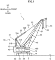
- FIG. 1 is a side view of a crane 1 (work machine) according to a first embodiment of the present invention. Note that, in FIG. 1 , a direction orthogonal to the paper surface corresponds to a left-right direction.
- the crane 1 includes an upper slewing body 12 (main body frame), a lower travelling body 14, a boom 16 (rising/lowering body), a lower spreader 19A, an upper spreader 19B, a pair of left and right boom guy lines 20, a gantry 21, a boom raising/lowering rope 22, a boom raising/lowering winch 30, a main winding winch 34, an auxiliary winding winch 35, a counterweight 40, and a pair of left and right backstops 45. Furthermore, the crane 1 includes a main winding rope 51, an auxiliary winding rope 52, a main hook 53, and an auxiliary hook 54. Note that, in the following description, the pair of left and right members has the left and right structures that are same, and therefore one of the left and right structures will be described.
- the upper slewing body 12 constitutes a crane body (machine body) of the crane 1, and is supported by the lower travelling body 14 so as to be slewable about a slewing center axis extending in an up-down direction.
- the lower travelling body 14 can travel on a travelling surface such as a ground G.
- the boom 16 is supported by the upper slewing body 12 to be capable of rising/lowering.
- a boom foot 16S included in a base end of the boom 16 is turnably supported by a shaft support part, not illustrated, of the upper slewing body 12.
- the boom 16 is a so-called lattice type, and is configured by coupling a plurality of boom members to each other.
- the structure of the boom 16 is not limited to this, and may be a box-like structure, a telescopic structure, or the like.
- the position for supporting the boom 16 is not limited to the front side of the upper slewing body 12, and may be the rear side.
- the pair of left and right backstops 45 is supported on the back surface of the boom 16.
- backstops 45 support the boom 16 from behind by each abutting against the upper slewing body 12 in a standing posture of the boom 16 (working posture of the crane 1). By this abutment, the backstop 45 is interposed between the upper slewing body 12 and the boom 16, and restricts the boom 16 from being tilted backward due to strong wind or the like.
- the lower spreader 19A is connected to the tip end of the gantry 21 and has a lower sheave block not illustrated.
- a plurality of sheaves is arrayed in a width direction (left-right direction).
- the upper spreader 19B is disposed at a predetermined interval in front of the lower spreader 19A.
- the upper spreader 19B is connected to a boom tip end via the boom guy line 20.
- the upper spreader 19B has an upper sheave block not illustrated. In the upper sheave block, a plurality of sheaves is arrayed in the width direction (left-right direction).
- the pair of left and right boom guy lines 20 is disposed at intervals to each other in the left-right direction orthogonal to the paper surface of FIG. 1 .
- a rear end of each of the boom guy lines 20 is connected to the upper spreader 19B, and a front end of each of the boom guy lines 20 is removably connected to a tip end of the boom 16.
- the boom guy line 20 may have any structure such as a guy link (metal plate material), a guy rope, or a guy wire (metal wire material).
- the gantry 21 is supported by the upper slewing body 12 at the rear of the boom 16. As illustrated in FIG. 1 , the gantry 21 is configured by two structures (a compression member 21A and a tension member 21B) forming a substantially triangular shape between the gantry 21 and the upper slewing body 12.
- the tension member 21B extends substantially vertically upward from the rear end of the upper slewing body 12.
- the compression member 21A connects an upper end of the tension member 21B and a substantially center part of the upper slewing body 12 along an oblique direction.
- the gantry 21 supports the boom 16 from behind so that the boom 16 is capable of rising/lowering.
- the upper slewing body 12, the gantry 21, and the backstop 45 constitute a machine body 1S of the present invention.
- the boom raising/lowering rope 22 is led out from the boom raising/lowering winch 30, hung on the sheave disposed at the tip end of the tension member 21B, and then wound a plurality of times between the lower sheave block of the lower spreader 19A and the upper sheave block of the upper spreader 19B. Note that the tip end of the boom raising/lowering rope 22 after being wound around the lower sheave block and the upper sheave block is fixed to the tip end (upper end) of the gantry 21.
- the boom raising/lowering winch 30 is disposed on the upper slewing body 12. By winding and unwinding the boom raising/lowering rope 22, the boom raising/lowering winch 30 changes the distance between the lower sheave block of the lower spreader 19A and the upper sheave block of the upper spreader 19B, and raises/lowers the boom 16 while turning the boom 16 relative to the gantry 21.
- the main winding winch 34 (winch) winds up and winds down a load to be suspended by the main winding rope 51 (suspended load rope).
- the main winding rope 51 is disposed to extend obliquely forward and upward from the main winding winch 34.
- a main winding point sheave is provided at the tip end of the boom 16.
- the main hook 53 connected to the load to be suspended is coupled to the main winding rope 51 led out from the main winding winch 34 and suspended from the main winding point sheave. The main hook 53 is thus hoisted and lowered when the main winding winch 34 winds up and releases the main winding rope 51.
- the auxiliary winding winch 35 (winch) winds up and winds down the load to be suspended by the auxiliary winding rope 52 (rope).
- auxiliary winding an auxiliary winding point sheave is provided at the tip end of the boom 16.
- the auxiliary hook 54 connected to the load to be suspended is coupled to the auxiliary winding rope 52 led out from the auxiliary winding winch 35 and suspended from an auxiliary winding point.
- the counterweight 40 is a weight loaded on the rear of the upper slewing body 12 in order to adjust the balance of the crane 1.
- the crane 1 further includes a rope inspection device 7.
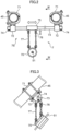
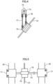
- FIG. 2 is a front view of the rope inspection device 7 of the crane 1 according to the present embodiment.
- FIGS. 3 , 4, and 5 are a side view, a side cross-sectional view, and a plan view of the same. Note that FIG. 4 corresponds to a cross section taken along line IV-IV in FIG. 2 .
- the rope inspection device 7 is provided on the backstop 45, and inspects the degree of deterioration and damage of the main winding rope 51.
- the rope inspection device 7 is detachable from the backstop 45.
- the rope inspection device 7 has a rope deterioration detector 70 (rope inspection unit) and a support unit 7S ( FIG. 2 ).
- the rope deterioration detector 70 can inspect a deterioration state of the main winding rope 51.
- the rope deterioration detector 70 has a cylindrical shape, and receives the main winding rope 51 in its cylindrical internal space.
- the rope deterioration detector 70 generates a magnetic field in the internal space, and detects deterioration of the main winding rope 51 by a change in the magnetic field.
- An inner peripheral surface of the rope deterioration detector 70 may be attached with a resin member or the like for enhancing the slidability of the main winding rope 51.
- the mechanism by which the rope deterioration detector 70 detects deterioration of the main winding rope 51 is not limited to the above magnetic one, and may be a mechanical one or an optical one.
- the rope deterioration detector 70 is not limited to a tubular shape, and may have a plate shape, a rectangular parallelepiped shape, or the like disposed to face the main winding rope 51.
- the support unit 7S is attached to the backstop 45 (attachment target portion).
- the support unit 7S supports the rope deterioration detector 70 so that the rope deterioration detector 70 can follow the movement of the main winding rope 51.
- the support unit 7S supports the rope deterioration detector 70 so as to be able to follow the movement of the main winding rope 51 in the direction intersecting the direction in which the main winding rope 51 extends.
- the support unit 7S has a pair of left and right clamp parts 71, a pair of left and right pin support members 72, a holder support pin 73 (support pin), a pair of left and right retaining portions 74, a holder 75, four rope layer change handling links 76, and four detector support chains 77.
- the clamp part 71 is a member for fixing the rope inspection device 7 to the left and right backstops 45. As illustrated in FIG. 2 , each clamp part 71 has a U shape that receives the backstop 45 therein, and is attached to the backstop 45 by fixing both ends thereof with fixing bolts. With the structure of the clamp part 71, the rope inspection device 7 can be easily attached to the backstop 45 of the existing crane 1 in a short time. Thus, the jig for attaching the rope inspection device 7 on the backstop 45 can be downsized, and the workability of the inspection of the main winding rope 51 can be improved.
- the holder support pin 73 is a pin extending in the left-right direction (horizontal direction) so as to connect the pair of left and right pin support members 72.
- a hole, not illustrated, into which the holder support pin 73 is inserted is formed in the pin support member 72.
- the pair of retaining portions 74 is attached to both ends of the holder support pin 73, respectively, and prevents the holder support pin 73 from coming off from each pin support member 72.
- the holder 75 is attached to the holder support pin 73 between the pair of left and right pin support members 72.
- a hole, not illustrated, into which the holder support pin 73 is inserted is also opened in the holder 75.
- the holder 75 is held by the holder support pin 73 so as to be relatively movable with respect to the holder support pin 73 along the direction in which the holder support pin 73 extends, and supports each rope layer change handling link 76.
- the four rope layer change handling links 76 are attached to the front, rear, left, and right corners of the holder 75, respectively.
- Each rope layer change handling link 76 is formed with an elongated hole extending in the up-down direction.
- Each detector support chain 77 has an upper end connected to a lower end of the rope layer change handling link 76 and a lower end connected to the rope deterioration detector 70. Note that the upper end of the detector support chain 77 has a pin structure that is inserted into the elongated hole of the rope layer change handling link 76, and as a result, the detector support chain 77 can move up and down relative to the rope layer change handling link 76. In this case, the detector support chain 77 functions as an up-down movement allowing unit of the present invention that allows the rope deterioration detector 70 to move up and down following the movement of the main winding rope 51 in the up-down direction.
- the two detector support chains 77 on the front side are set to be shorter than the two detector support chains 77 on the rear side.
- the front detector support chain 77 and the rear detector support chain 77 (a pair of front and rear support links) support the rope deterioration detector 70 in an inclined manner along the direction in which the main winding rope 51 extends.
- clamp part 71, the pin support member 72, the holder support pin 73, the retaining portion 74, and the holder 75 constitute a support mechanism of the present invention supported by the backstop 45 (machine body 1S).
- the rope layer change handling link 76 and the detector support chain 77 constitute a support link of the present invention.
- the support link is suspended from the support mechanism and swingably supports the rope deterioration detector 70.
- the support unit 7S supports the rope deterioration detector 70 so that the rope deterioration detector 70 capable of inspecting the deterioration state of the main winding rope 51 can follow the movement of the main winding rope 51.
- the support unit 7S is attached to the machine body 1S (backstop 45) of the work machine. With such a configuration, even when the position of the main winding rope 51 changes with the operation of the crane 1, the rope deterioration detector 70 can move following the main winding rope 51, so that the inspection of the main winding rope 51 can be stably performed.
- the backstop 45 on the upper slewing body 12 can be used to stably support the rope inspection unit.
- the rope layer change handling link 76 and the detector support chain 77 swingably support the rope deterioration detector 70, the rope deterioration detector 70 can easily move following the main winding rope 51 even when the position of the main winding rope 51 changes.
- the posture of the rope deterioration detector 70 can be maintained in an inclined manner along the direction in which the main winding rope 51 extends from the main winding winch 34.
- FIG. 6 is a schematic side view illustrating the main winding rope 51 extending from the main winding winch 34.
- FIG. 7 is a side view comparing two states of the rope inspection device 7.
- the main winding winch 34 has a drum shaft portion 34A and a drum flange 34B.
- the main winding rope 51 is wound so as to form a plurality of layers on the drum shaft portion 34A.
- the layer of the main winding rope 51 on the main winding winch 34 changes, so that the position of the main winding rope 51 led out changes up and down as indicated by a chain line and a solid line in FIG. 6 .
- the detector support chain 77 can move up and down relative to the rope layer change handling link 76. As a result, the position of the rope deterioration detector 70 in the up-down direction can be changed by the height H.
- the rope layer change handling link 76 and the detector support chain 77 can allow the rope deterioration detector 70 to move up and down following the movement of the main winding rope 51 in the up-down direction.
- the rope deterioration detector 70 can move following the main winding rope 51. Accordingly, the rope deterioration detector 70 can stably detect the deterioration state of the main winding rope 51 while the main winding winch 34 unwinds or winds the main winding rope 51.
- the holder 75 can move along the holder support pin 73.
- the rope deterioration detector 70 can move following the main winding rope 51.
- inspection of the main winding rope 51 by the rope inspection device 7 may be performed during the operation of the crane 1, or may be performed after end or before start of the work. In either case, it is not necessary to cause the boom 16 to tilt with respect to the upper slewing body 12 in order to inspect the main winding rope 51.
- the rope inspection device 7 since it is possible to constantly monitor the main winding rope 51 by the rope inspection device 7, it is possible to prevent damage of the main winding rope 51 due to overlooking from becoming severe as compared with a case of visual inspection and confirmation by the operator. Further, when the work site of the crane 1 is narrow and it is difficult to attach and detach the rope inspection device 7, the rope inspection device 7 can be kept attached to the crane 1.
- the rope inspection device 7 can be easily attached to and detached from the backstop 45 in the pair of left and right clamp parts 71.
- the operator can easily attach and detach the rope inspection device 7 while standing on the upper slewing body 12.
- the rope inspection device 7 may be removed from the backstop 45, and the rope inspection device 7 may be attached to the backstop 45 when the operation of the crane is not performed to detect the deterioration state of the main winding rope 51.
- the weight of the crane 1 itself can be reduced during the operation of the crane 1.
- each member of the crane 1 can be transported while satisfying the transport weight limit. Note that, in order to easily attach the main winding rope 51 inside the rope deterioration detector 70, it is desirable that the rope deterioration detector 70 be separable into two members.
- FIGS. 8 and 9 are front views of a rope inspection device 7 of a crane 1 according to the present embodiment.
- members having the same functions and structures as those of the first embodiment are denoted by the same reference numerals. The same applies to each embodiment described later.
- a plurality of length adjusting holes 73P is formed at one end of the holder support pin 73.
- a retaining portion 74 can be attached to each of the length adjusting holes 73P.
- the rope inspection device 7 can be attached to the crane 1 in which the width of the left and right backstops 45 is L1.
- the rope inspection device 7 can be attached to the crane 1 in which the width of the left and right backstops 45 is L2.
- the rope inspection device 7 can be attached to the crane 1 in which the width of the left and right backstops 45 is L2.
- the rope inspection device 7 can be attached in a further variety of cranes 1.
- the support mechanism of the rope inspection device 7 further includes the pair of left and right clamp parts 71 (attachment portions) attached to the backstop 45, and the plurality of length adjusting holes 73P (width adjusting parts) capable of adjusting the width of the pair of left and right clamp parts 71 in the left-right direction.
- the width of the left and right clamp parts 71 is adjusted according to the width dimension in the left-right direction of the machine body 1S represented by the backstop 45, and the rope inspection device 7 can be easily attached to various types of backstops 45.
- FIG. 10 is a front view of a rope inspection device 7 of a crane 1 according to the present embodiment.
- the support unit 7S of the rope inspection device 7 further includes a pair of left and right length adjusting units 78.
- the length adjusting unit 78 can adjust the length of the detector support chain 77 between the rope layer change handling link 76 and the rope deterioration detector 70.
- On the rear side of the detector support chain 77 in FIG. 10 the tip end of the detector support chain 77 folded back at the length adjusting unit 78 is suspended.
- the length adjusting unit 78 has a lever structure, and when an operator pulls the lever, the length of the detector support chain 77 can be changed. After the length of the detector support chain 77 is adjusted, the length of the detector support chain 77 is fixed when the operator returns the lever.
- the length adjusting unit 78 adjusts the length of the detector support chain 77, thereby adjusting the position of the rope deterioration detector 70 in the up-down direction with respect to the holder support pin 73 (relative height K in FIG. 10 ).
- the length adjusting unit 78 functions as an up-down position adjustment unit capable of adjusting the position (height) of the rope deterioration detector 70 in the up-down direction with respect to the upper slewing body 12.
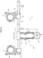
- FIGS. 11 , 12, and 13 are a front view, a side view, and a plan view of a rope inspection device 7 of a crane according to the present embodiment.
- the rope inspection device 7 is attached to a pair of left and right compression members 21A (attachment target portions).
- the rope deterioration detector 70 of the rope inspection device 7 detects a deterioration state of the auxiliary winding rope 52 led out from the auxiliary winding winch 35.
- each of the pair of left and right compression members 21A of the gantry 21 is a box-shaped member having a rectangular cross section.
- the clamp part 71 also has a U-shaped (square-shaped U-shaped) cross section capable of accommodating the compression member 21A, and the opening is closed by a bolt, whereby the clamp part 71 is fixed to the compression member 21A.
- the holder 75 can move left and right along the holder support pin 73 stretched between the pair of left and right compression members 21A.
- the rope deterioration detector 70 supported by the rope layer change handling link 76 and the detector support chain 77 from the holder 75 accommodates the auxiliary winding rope 52 therein and detects a deterioration state thereof.
- the compression member 21A of the gantry 21 is erected on the upper slewing body 12 behind the boom 16, and functions as a rear support body that supports the boom 16 from behind. Then, the support unit 7S of the rope inspection device 7 is attached to the compression member 21A. With such a configuration, the rope deterioration detector 70 can be supported using the compression member 21A on the upper slewing body 12.
- the compression member 21A and the tension member 21B of the gantry 21 have high rigidity and strength to support the boom 16, and thus it is possible to stably support the rope deterioration detector 70.
- the rear support body supporting the boom 16 behind the boom 16 is not limited to the gantry 21, and may be a mast.
- the operator can easily attach and detach the rope inspection device 7 while standing on the upper slewing body 12.
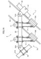
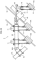
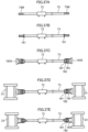
- FIGS. 14 and 15 are a side view and a plan view of a rope inspection device 7 of a crane according to the present embodiment.
- FIGS. 16 and 17 are cross-sectional views of a clamp part of the rope inspection device 7 of the crane 1 according to the present embodiment.
- the backstop 45 extending obliquely forward and upward from the upper slewing body 12 and the compression member 21A extending obliquely backward and upward from the upper slewing body 12 cooperate to support the rope inspection device 7.
- the machine body 1S of the crane 1 further includes a pair of left and right bridging portions 8 (attachment target portions). Each bridging portion 8 is disposed above the upper slewing body 12 so as to connect the backstop 45 and the compression member 21A along the front-rear direction.
- Each bridging portion 8 has an intermediate portion 80 and clamp parts 81 and 82 disposed respectively at both ends of the intermediate portion 80.
- the clamp part 81 is attached to the backstop 45, and the clamp part 82 is attached to the compression member 21A.
- the clamp part 81 has a shape capable of accommodating the cylindrical backstop 45
- the clamp part 82 has a shape capable of accommodating the box-shaped compression member 21A.
- the clamp part 81 has a pin connection part 81A, and the pin connection part 81A turnably supports the front end of the intermediate portion 80.
- the clamp part 82 has a pin connection part 82A, and the pin connection part 82A turnably supports the rear end of the intermediate portion 80.
- two front and rear holder support pins 73 are supported by pin support members 72 at the intermediate portion 80 of the left and right bridging portions 8.
- Each of the holder support pins 73 supports the rope deterioration detector 70A and the rope deterioration detector 70B with a structure similar to that of the first embodiment.
- the rope deterioration detector 70A detects a deterioration state of the auxiliary winding rope 52 led out from the auxiliary winding winch 35
- the rope deterioration detector 70B detects a deterioration state of the third rope 55 led out from the third winch not illustrated.
- the rope deterioration detectors 70A and 70B are attached to and supported by the bridging portion 8.
- the rope deterioration detectors 70A and 70B can be stably supported using the bridging portion 8 disposed between the backstop 45 on the upper slewing body 12 and the compression member 21A.
- the dedicated rope deterioration detectors 70A and 70B are disposed on each rope, it is not necessary to move the rope inspection device 7 for inspecting a plurality of ropes.
- only one of the rope deterioration detectors 70A and 70B may be supported by the bridging portion 8.
- the mast may support the rope inspection device 7 together with the backstop 45 instead of the gantry 21 (compression member 21A).
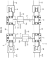
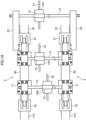
- FIGS. 18 and 19 are a side view and a plan view of a rope inspection device of a crane according to the present embodiment.
- the pair of left and right bridging portions 8 further has a pair of left and right cantilever members 83 (protrusions).
- the cantilever member 83 is connected to the intermediate portion 80 located between the backstop 45 and the compression member 21A in the bridging portion 8.
- the cantilever member 83 is disposed so as to protrude forward from the backstop 45.
- the holder support pin 73 is also supported by front end portions of the pair of left and right cantilever members 83.
- the holder support pin 73 supports the holder 75, and the holder 75 supports a rope deterioration detector 70C via the rope layer change handling link 76 and the detector support chain 77.
- the rope deterioration detector 70C detects a deterioration state of the main winding rope 51 led out from the main winding winch 34.
- the rope deterioration detectors 70A and 70B are supported by the intermediate portion 80, and the rope deterioration detector 70C is supported by the cantilever member 83.
- the rope deterioration detectors 70 (70A, 70B, and 70C) can be stably supported using the intermediate portion 80 between the backstop 45 and the compression member 21A or the cantilever member 83 (protrusion) protruding forward from the backstop 45.
- the rope deterioration detectors 70A, 70B, or 70C may be disposed.
- the rope deterioration detector may be supported by a cantilever member (protrusion), not illustrated, protruding rearward from the compression member 21A.
- FIGS. 20 and 21 are a front view and a side view of a rope inspection device 7 of a crane according to the present embodiment.
- FIG. 22 is a perspective view illustrating a drum cover 3F on which the rope inspection device 7 of the crane 1 according to the present embodiment is attached.
- the support unit 7S of the rope inspection device 7 has a pair of left and right support legs 90.
- Each support leg 90 has a leg main body 91, an expansion/contraction part 92, a fixing pin 93, and a pin support member 94.
- the leg main body 91 corresponds to a lower end of the support leg 90 and has a tubular shape.
- the expansion/contraction part 92 is inserted into the tube of the leg main body 91 and extends and contracts in the up-down direction with respect to the leg main body 91.
- the fixing pin 93 fixes the expansion/contraction part 92 so as to prevent the relative movement of the expansion/contraction part 92 with respect to the leg main body 91.
- the pin support member 94 is disposed at the upper end of the expansion/contraction part 92 and supports the holder support pin 73.
- the boom raising/lowering winch 30, the main winding winch 34, and the auxiliary winding winch 35 are disposed on the upper slewing body 12 side by side in the front-rear direction.
- a winch drum of each winch is protected by a pair of left and right drum covers 3F (attachment target portions) disposed on the upper slewing body 12.
- a leg fixing unit 3H that supports the leg main body 91 of the support leg 90 is disposed on the upper surface of drum cover 3F.
- each winch has a rotatable winch drum, and the support unit 7S of the rope inspection device 7 is attached (fixed) to the drum cover 3F that protects the winch drum.
- the rope deterioration detector 70 can be stably supported using the drum cover 3F disposed on the upper slewing body 12.
- the operator can easily attach and detach the rope inspection device 7 while standing on the upper slewing body 12.
- the rope inspection device 7 is attached to the drum cover 3F as in the present embodiment, it is possible to install the rope inspection device 7 without being affected by rising/lowering and posture changes of the boom 16, the backstop 45, and the gantry 21.
- the drum cover 3F in FIG. 22 is disposed between the pair of left and right backstops 45 ( FIG. 1 ) in the left-right direction, in other words, between the pair of left and right compression members 21A.
- the rope inspection device 7 does not become an obstacle, and the space on the upper slewing body 12 can be effectively used.
- the pair of support legs 90 of the rope inspection device 7 of FIGS. 20 and 21 may be fixed (attached) on the guard 13 disposed on the upper slewing body 12 of FIG. 1 .
- the guard 13 protects a predetermined device such as an engine on the upper slewing body 12.
- the rope deterioration detector 70 can be stably supported using the guard 13 disposed on the upper slewing body 12. Also in this case, the operator can easily perform the attaching and detaching work of the rope inspection device 7 while standing on the upper slewing body 12.
- the leg main body 91 and the expansion/contraction part 92 may have a cylinder structure exemplified by a hydraulic cylinder, and the expansion/contraction part 92 expands/contracts with respect to the leg main body 91.
- the hydraulic cylinder may be expanded and contracted so that the rope deterioration detector 70 can follow the movement of the rope according to the vertical movement of the rope.
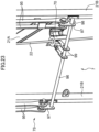
- FIGS. 23 , 24 , and 25 are a perspective view, a side view, and a plan view of a rope inspection device of a crane according to the present embodiment.
- the rope inspection device 7 is attached to the tension member 21B (attachment target portion) of the gantry 21 of FIG. 1 .
- the support unit 7S of the rope inspection device 7 has a pair of left and right pin support links 95, a holder support pin 96, a pair of left and right fixing members 97, a pair of left and right retaining portions 98, and a pair of left and right connecting arms 99.
- the rope deterioration detector 70 of the rope inspection device 7 detects a deterioration state of the boom raising/lowering rope 22 led out from the boom raising/lowering winch 30 ( FIG. 1 ).
- the pair of left and right pin support links 95 is swingably supported by an upper end (top) of the gantry 21 (tension member 21B).
- the pin support link 95 extends in the up-down direction along the tension member 21B immediately behind the tension member 21B.
- Each pin support link 95 includes a pair of left and right plate-like members.
- the fixing member 97 is attached to the lower end portion of the pin support link 95, and the holder support pin 96 is supported by the pair of left and right fixing members 97.
- the pair of left and right retaining portions 98 prevents the fixing member 97 from coming off from the holder support pin 96 at both ends of the holder support pin 96.
- the pair of left and right connecting arms 99 is disposed so as to extend rearward from the rope deterioration detector 70.
- Each connecting arm 99 is formed with a long hole 99A ( FIG. 24 ) that is long in the front-rear direction.
- the rope inspection device 7 is supported by the gantry 21 (tension member 21B), so that the rope deterioration detector 70 can stably detect the deterioration state of the boom raising/lowering rope 22.
- the connecting arm 99 can relatively move in the front-rear direction with respect to the holder support pin 96 by the length of the long hole 99A, so that the rope deterioration detector 70 can move in the front-rear direction following the boom raising/lowering rope 22 as indicated by an arrow in FIG. 25 .
- the pair of left and right connecting arms 99 move left and right along the holder support pin 96, so that the rope deterioration detector 70 can move left and right so as to follow the boom raising/lowering rope 22 as indicated by the arrow in FIG. 25 .
- the pin support link 95 swinging back and forth about the top of the gantry 21 as a fulcrum, the rope deterioration detector 70 may follow the forward and backward movement of the boom raising/lowering rope 22.
- FIG. 26 is a plan view of a rope inspection device of a crane according to the present embodiment.
- the present embodiment is different from the eighth embodiment in that it has a plurality of length adjusting holes 96P at an end of the holder support pin 96.
- a left and right width L of the support unit 7S of the rope inspection device 7 can be adjusted according to the width of the tension members 21B, and the rope inspection device 7 can be easily attached to the tension members 21B.
- FIG. 26 is a plan view of a rope inspection device of a crane according to the present embodiment.
- the present embodiment is different from the eighth embodiment in that the holder support pin 96 has a cylinder structure including a pin main body 96A and an expansion/contraction part 96B. Even in such a configuration, when the left and right width of the tension members 21B is different according to the specification of the crane 1, the left and right width L of the support unit 7S of the rope inspection device 7 is adjusted according to the width of the tension members 21B, and the rope inspection device 7 can be easily attached to the tension members 21B.
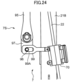
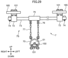
- FIG. 28 is an enlarged side view of a boom 16 of a crane 1 according to the present embodiment.
- FIGS. 29 and 30 are a front view and a side view of a rope inspection device 7 of the crane 1 according to the present embodiment.
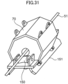
- FIG. 31 is a perspective view of a rope deterioration detector 70 of the crane 1 according to the present embodiment.
- FIG. 28 illustrates a state in which the boom 16 is tilted with respect to the upper slewing body 12.
- the boom 16 has a pair of left and right first main members 161, a pair of left and right second main members 162, a plurality of connecting members 163, a plurality of lattice members 164, a pair of left and right scaffolding members 165 (extending members), and a guide sheave 166.
- Each of the first main member 161 and the second main member 162 forms a rectangular cross-sectional shape of the boom 16, and is a member extending in a longitudinal direction thereof at four corners of the boom 16. Note that, in FIG. 28 , the first main member 161 and the second main member 162 on the front side of the paper surface appear.
- the plurality of connecting members 163 connect the first main member 161 and the second main member 162, or connect each of the pair of left and right first main members 161 and the pair of left and right second main members 162.
- the plurality of lattice members 164 also connect the respective members similar to the plurality of connecting members 163. Note that, each lattice member 164 is a member extending obliquely with respect to the longitudinal direction of the boom 16.
- the pair of left and right scaffolding members 165 is disposed along the pair of left and right first main members 161. Each scaffolding member 165 is used when the operator moves on the boom 16. Note that, in the present embodiment, the pair of left and right scaffolding members 165 is disposed more inside in the left-right direction than the pair of left and right first main members 161.
- the guide sheave 166 is rotatably supported on a belly surface side (upper surface side in FIG. 28 ) of the boom 16.
- the guide sheave 166 has a function of guiding the main winding rope 51 led out from the main winding winch 34 toward the tip end of the boom 16.
- the winch 30, the main winding winch 34, and the auxiliary winding winch 35 are mounted on the proximal end side (lower boom) of the boom 16.
- the winch 30 corresponds to a jib winch, a 3rd winch, a miscellaneous winch, and the like.
- the rope inspection device 7 is attached to the pair of left and right scaffolding members 165.
- the support unit 7S of the rope inspection device 7 has a pair of left and right scaffolding fixing parts 101.
- Each scaffolding fixing part 101 is a member for fixing the pin support member 72 of the support unit 7S to the scaffolding member 165.
- Each scaffolding fixing part 101 has a plurality of bolts. The bolt is inserted into a bolt hole, not illustrated, formed in the scaffolding member 165 and fastened to the pin support member 72.
- the support unit 7S is supported by the scaffolding members 165 on both left and right sides of the boom 16. Therefore, the rope deterioration detector 70 can be stably supported without falling off using the boom 16 having high rigidity.
- the rope deterioration detector 70 supported by the support unit 7S ( FIG. 29 ) is disposed inside the boom 16, and can inspect the deterioration state of the main winding rope 51 extending from the main winding winch 34 toward the guide sheave 166.
- the rope deterioration detector 70 does not protrude outside the boom 16, an increase in the height of the boom 16 during transportation is suppressed. Further, the boom 16 can be transported without removing the rope inspection device 7 from the boom 16.
- the support unit 7S has a pair of support rollers 150 (rising/lowering support members) and a roller attachment portion 151.
- the roller attachment portion 151 is attached to the rope deterioration detector 70 and rotatably supports the pair of support rollers 150.
- the pair of support rollers 150 is a roller having an outer peripheral surface that supports the main winding rope 51. As illustrated in FIG. 32 , the pair of support rollers 150 is disposed on both sides of the rope deterioration detector 70 in the direction in which the main winding rope 51 extends. Note that, in FIG. 32 , the support roller 150 on the front side appears. As a result, the support roller 150 comes into contact with the main winding rope 51 at a predetermined rising/lowering angle of the boom 16, whereby the rope deterioration detector 70 and the main winding rope 51 can be prevented from coming into contact with each other (see FIG. 35B ). As a result, damage to the rope deterioration detector 70 is suppressed.
- the maintenance cost of the rope deterioration detector 70 can be reduced.
- the main winding rope 51 can be inspected by the rope deterioration detector 70 in a state where the boom 16 stands up with respect to the upper slewing body 12, it is possible to periodically inspect the main winding rope 51 without requiring removal at the time of transportation, tilting and landing of the boom 16, and it is possible to prevent the main winding rope 51 from becoming serious due to overlooking of the operator or the like.
- the support unit 7S since the support unit 7S has the rotatable support rollers 150 as a member that supports the main winding rope 51, it is possible to prevent a large load from being applied to the rope and the rope deterioration detector 70 by the outer peripheral surface of the roller coming into contact with the rope. Further, since the support rollers 150 come into contact with the main winding rope 51 on both sides of the rope inspection unit, it is possible to stably prevent contact between the main winding rope 51 and the rope deterioration detector 70.
- the rope inspection device 7 can be installed using the scaffolding member 165 conventionally attached to the boom 16.
- the scaffolding member 165 conventionally attached to the boom 16.
- FIG. 32 is an enlarged side view of a boom 16 of a crane 1 according to the present embodiment.
- the present embodiment is different from the eleventh embodiment in that the rope inspection device 7 is attached to the pair of left and right first main members 161.
- the rope inspection device 7 can be attached to the pair of left and right first main members 161 using the clamp part 71 similar to that in FIG. 10 described above.
- the rope inspection device 7 can be installed on the first main member 161 of the boom 16, it is possible to stably inspect the rope such as the main winding rope 51 even when there is a winch drum such as the main winding winch 34 in the boom 16.
- the bridging portion 8 of FIG. 14 may be attached to the pair of lattice members 164 illustrated in FIG. 28 , and the rope inspection device 7 may be supported by the bridging portion 8.
- the bridging portion 8 may be attached to the pair of connecting members 163. Even when there is no appropriate installation location of the rope inspection device 7 on the first main member 161 or the like, the rope inspection device 7 can be installed using the lattice member 164 or the like, so that the main winding rope 51 can be stably inspected. In particular, as illustrated in FIG. 28 , even when the extending directions of the pair of lattice members 164 are different, the support unit 7S can be stably supported by the bridging portion 8.
- the main winding winch 34 and the main winding rope 51 are used, but the rope inspection device 7 is also applicable to other winches illustrated in FIGS. 28 and 32 and other ropes delivered from the winches.
- FIGS. 33 and 34 are side views of a crane 1 according to the present embodiment.
- FIGS. 35A and 35B are side views illustrating the posture of the rope deterioration detector 70 in the crane according to the present embodiment.
- FIG. 36 is a front view of the rope inspection device 7 of the crane 1 according to the present embodiment.
- FIGS. 37A, 37B, 37C, 37D, and 37E are process diagrams illustrating an attachment procedure of the support unit 7S of the rope inspection device 7 of the crane 1 according to the present embodiment.
- the crane 1 has a pair of left and right masts 23 (rising/lowering body). Each mast 23 is turnably supported by the upper slewing body 12 behind the boom 16, and functions as a support supporting the boom 16 from behind.
- the boom raising/lowering winch 30 is mounted on the upper slewing body 12, and the boom raising/lowering rope 22 led out from the boom raising/lowering winch 30 is stretched between sheaves, not illustrated, disposed respectively at the tip end of the mast 23 and the rear end of the upper slewing body 12.
- the boom raising/lowering winch 30 winds up and winds out the boom raising/lowering rope 22, the boom 16 is raised and lowered integrally with the mast 23.
- the rope inspection device 7 is supported by the mast 23, and deterioration of the boom raising/lowering rope 22 can be inspected.
- the mast 23 changes its posture between a standing posture extending rearward and upward from the upper slewing body 12 as illustrated in FIG. 33 and a tilting posture extending forward and upward from the upper slewing body 12 as illustrated in FIG. 34 .
- the mast 23 can be tilted further downward than in FIG. 34 .
- the rope deterioration detector 70 is supported by the detector support chain 77 in the standing posture of the mast 23 as illustrated in FIG. 35A
- the detector support chain 77 is loosened when the mast 23 is in the tilting posture as illustrated in FIG. 35B , so that the position of the rope deterioration detector 70 may become unstable.
- the support unit 7S of the rope inspection device 7 has the support rollers 150 and the roller attachment portion 151. Therefore, even in the posture as illustrated in FIG. 35B , the support rollers 150 come into contact with the boom raising/lowering rope 22, so that the relative position between the rope deterioration detector 70 and the boom raising/lowering rope 22 can be stably maintained.
- the support unit 7S is attached on inner surfaces of the pair of left and right masts 23.
- the support unit 7S includes a holder support pin 73 (support pin), and further has a pair of left and right width adjusting parts 180, as in each of the above embodiments.
- the width adjusting part 180 can adjust the width of a portion of the support unit 7S attached on the left and right inner surfaces of the mast 23.
- each of the left and right width adjusting parts 180 has a nut 181, a washer 182, and an attachment portion 183.
- the attachment portion 183 has a cylindrical shape, and a hole portion for receiving the holder support pin 73 is opened in an axially inner portion thereof.
- the pin support member 72 supporting the rope deterioration detector 70 is attached to the holder support pin 73.
- nuts 181 are attached to deep sides of screw portions 73M on both sides of the holder support pin 73.
- the washer 182 and the attachment portion 183 are inserted into the screw portion 73M.
- the holder support pin 73 is disposed between the pair of left and right masts 23. At this time, there is a gap between an abutting portion 183S of the attachment portion 183 and the inner surface of the mast 23.
- the width adjusting part 180 adjusts the interval between the pair of left and right attachment portions 183 in the left-right direction, thereby biasing the attachment portions 183 toward the inner surface of the mast 23.
- the rope deterioration detector 70 can be easily attached in accordance with the size between the left and right masts 23.
- the holder support pin 73 and each member for attaching the holder support pin 73 are accommodated between the left and right masts 23, and the rope inspection device 7 does not protrude from the left and right masts 23 to the opposite side of the rope deterioration detector 70 as indicated by a one-dot chain line in FIG. 36 , so that the degree of freedom of the layout of surrounding members can be increased.
- FIGS. 38 and 39 are a front view and a plan view of a rope inspection device 7 of a crane 1 according to the present embodiment. While an aspect in which the inner surfaces of the left and right masts 23 extend in parallel has been described in the thirteenth embodiment, the inner surfaces of the left and right masts 23 may be inclined in a forward spreading manner as illustrated in FIG. 39 .
- the width adjusting part 180 of the support unit 7S further has a swing part 184 and a fulcrum part 185.
- the swing part 184 is attached on an outer side of the attachment portion 183 and abuts against the inner surface of the mast 23.
- the swing part 184 is supported by the attachment portion 183 so as to be swingable about the fulcrum part 185.
- the fulcrum part 185 extends in a direction orthogonal to a plane including the left and right masts 23 (a direction orthogonal to the paper surface of FIG. 39 ).
- the support unit 7S can be stably attached even on the inner surface of the inclined mast 23. Note that the other attachment procedure of the support unit 7S is similar to that of the thirteenth embodiment.
- FIG. 40 is a front view of a rope inspection device 7 of a crane 1 according to the present embodiment. While an aspect in which the support rollers 150 are disposed on one side of the boom raising/lowering rope 22 when viewed in a cross section orthogonal to the boom raising/lowering rope 22 has been described in the thirteenth and fourteenth embodiments, the support rollers 150 may be disposed on both sides of the boom raising/lowering rope 22 as illustrated in FIG. 40 .
- the pair of support rollers 150 is disposed so as to sandwich the boom raising/lowering rope 22 from both sides, and thus the relative positional relationship between the rope deterioration detector 70 and the boom raising/lowering rope 22 can be stably maintained even in various postures of the mast 23 with respect to the upper slewing body 12.
- the support rollers 150 are disposed on both sides of the rope deterioration detector 70 in the direction in which the main winding rope 51 extends.
- three or more support rollers 150 may be disposed so as to surround the boom raising/lowering rope 22.
- the rope inspection device 7 according to each of the embodiments of the present invention and the crane 1 including the same have been described above. With the crane 1 including the rope inspection device 7 as described above, the rope deterioration detector 70 can move following each rope, so that it is possible to stably inspect the rope. Note that the present invention is not limited to these embodiments. In the present invention, modified embodiments as follows are possible.
- a rope inspection device is a rope inspection device attached to a work machine having a machine body, a rising/lowering body capable of rising/lowering relative to the machine body, a winch, and a rope that is led out from the winch, the rope inspection device including a rope inspection unit capable of inspecting a deterioration state of the rope, and a support unit attached to a predetermined attachment target portion of the work machine, the support unit supporting the rope inspection unit so that the rope inspection unit is able to follow movement of the rope.
- the support unit supports the rope inspection unit so that the rope inspection unit capable of inspecting a deterioration state of the rope is able to follow movement of the rope.
- the support unit is attached on a predetermined attachment target portion of the work machine.
- a rope inspection device is the rope inspection device according to the first aspect, in which the support unit has a support mechanism supported by the attachment target portion, and a support member that is suspended from the support mechanism and swingably supports the rope inspection unit.
- the support member swingably supports the rope inspection unit, the rope inspection unit can easily move following the rope even when the position of the rope changes.
- a rope inspection device is the rope inspection device according to the second aspect, in which the rope is disposed to extend obliquely upward from the winch, and the support member tilts and supports the rope inspection unit along a direction in which the rope extends.
- the posture of the rope inspection unit can be maintained along the direction in which the rope extends from the winch.
- a rope inspection device is the rope inspection device according to the second or third aspect, in which the support member has an up-down movement allowing unit that allows the rope inspection unit to move up and down following the movement of the rope in an up-down direction.
- the rope inspection unit can move following the rope.
- a rope inspection device is the rope inspection device according to any one of the second to fourth aspects, in which the support mechanism has an up-down position adjustment unit capable of adjusting a position of the rope inspection unit in an up-down direction with respect to the attachment target portion.
- the position of the rope inspection unit in the up-down direction can be easily adjusted according to the position of the winch and the position of the rope led out from the winch.
- a rope inspection device is the rope inspection device according to any one of the second to fifth aspects, in which the support mechanism has a support pin and a holder that is held by the support pin so as to be relatively movable with respect to the support pin along a direction in which the support pin extends, and supports the support member.
- the rope inspection unit can move following the rope.
- a rope inspection device is the rope inspection device according to any one of the second to sixth aspects, in which the support mechanism has at least a pair of left and right attachment portions attached to the attachment target portion, and a width adjusting part capable of adjusting a width of at least the pair of left and right attachment portions in a left-right direction.
- the width of the attachment portion can be adjusted according to the width dimension of the machine body in the left-right direction, and the rope inspection device can be easily attached to the machine body.
- a rope inspection device is the rope inspection device according to any one of the second to fifth aspects, in which the attachment target portion has a pair of left and right inner surfaces disposed to face each other, and the support mechanism has a support pin that supports the support member, a pair of left and right attachment portions disposed at both ends of the support pin, and a pair of left and right width adjusting parts that bias the pair of left and right attachment portions toward the pair of left and right inner surfaces by adjusting an interval between the pair of left and right attachment portions in the left-right direction.
- the pair of left and right width adjusting parts biases the attachment portions toward the inner surfaces, so that the rope inspection unit can be easily attached in accordance with the size of the attachment target portion.
- a rope inspection device is the rope inspection device according to any one of the first to eighth aspects, in which the machine body of the work machine has a main body frame that supports the rising/lowering body so that the rising/lowering body is capable of rising/lowering, and a backstop that is interposed between the main body frame and the rising/lowering body and supports the rising/lowering body from behind, and the support unit is attached to the backstop as the attachment target portion.
- the rope inspection unit can be stably supported using the backstop on the main body frame.
- a rope inspection device is the rope inspection device according to any one of the first to eighth aspects, in which the machine body of the work machine has a main body frame that supports the rising/lowering body so that the rising/lowering body is capable of rising/lowering, and a rear support body erected on the main body frame behind the rising/lowering body, the rear support body including a gantry or a mast supporting the rising/lowering body from behind, and the support unit is attached to the rear support body as the attachment target portion.
- the rope inspection unit can be stably supported using the rear support body on the main body frame.
- a rope inspection device is the rope inspection device according to any one of the first to eighth aspects, in which the machine body of the work machine has a main body frame that supports the rising/lowering body so that the rising/lowering body is capable of rising/lowering, a backstop that is interposed between the main body frame and the rising/lowering body and supports the rising/lowering body from behind, a rear support body erected on the main body frame behind the backstop, the rear support body including a gantry or a mast supporting the rising/lowering body from behind, and a bridging portion disposed above the main body frame so as to connect the backstop and the rear support body along a front-rear direction, and the support unit is attached to the bridging portion as the attachment target portion.
- the rope inspection unit can be stably supported using the bridging portion disposed between the backstop on the main body frame and the rear support body.
- a rope inspection device is the rope inspection device according to the eleventh aspect, in which the bridging portion has an intermediate portion positioned between the backstop and the rear support body, and a protrusion connected to the intermediate portion and disposed to protrude from the backstop or the rear support body, and the support unit is attached to at least one of the intermediate portion or the protrusion.
- a rope inspection device is the rope inspection device according to any one of the first to eighth aspects, in which the machine body of the work machine has a main body frame that supports the rising/lowering body so that the rising/lowering body is capable of rising/lowering, and a guard that is disposed on the main body frame and protects a predetermined device, and the support unit is attached to the guard as the attachment target portion.
- the rope inspection unit can be stably supported using the guard disposed on the main body frame.
- a rope inspection device is the rope inspection device according to any one of the first to eighth aspects, in which the winch includes a rotatable winch drum, the machine body of the work machine has a main body frame that supports the rising/lowering body so that the rising/lowering body is capable of rising/lowering, and a drum cover that is disposed on the main body frame and protects the winch drum, and the support unit is attached on the drum cover as the attachment target portion.
- the winch includes a rotatable winch drum
- the machine body of the work machine has a main body frame that supports the rising/lowering body so that the rising/lowering body is capable of rising/lowering, and a drum cover that is disposed on the main body frame and protects the winch drum, and the support unit is attached on the drum cover as the attachment target portion.
- the rope inspection unit can be stably supported using the drum cover disposed on the main body frame.
- a rope inspection device is the rope inspection device according to any one of the first to eighth aspects, in which the support unit is attached on the rising/lowering body as the attachment target portion.
- the rope inspection unit can be stably supported using the rising/lowering body supported by the machine body.
- a rope inspection device is the rope inspection device according to the fifteenth aspect, in which the support unit further includes a rising/lowering support member that prevents contact between the rope and the rope inspection unit by coming into contact with the rope at a predetermined rising/lowering angle of the rising/lowering body relative to the machine body.
- the rising/lowering support member comes into contact with the rope at the predetermined rising/lowering angle of the rising/lowering body, whereby the rope inspection unit and the rope can be prevented from coming into contact with each other.
- a rope inspection device is the rope inspection device according to the sixteenth aspect, in which the rising/lowering support member includes at least one roller including an outer peripheral surface capable of supporting the rope.
- a rope inspection device is the rope inspection device according to the seventeenth aspect, in which the at least one roller includes a pair of rollers disposed on both sides of the rope inspection unit in a direction in which the rope extends.
- a rope inspection device is the rope inspection device according to any one of the fifteenth to eighteenth aspects, in which the rising/lowering body has at least a pair of extending members, and the support unit is attached to the pair of extending members.
- the support unit can be stably supported using the pair of extending members of the rising/lowering body.
- a rope inspection device is the rope inspection device according to the nineteenth aspect, in which the pair of extending members is a pair of scaffolding members movable by an operator.
- the support unit can be stably supported using the scaffolding members of the rising/lowering body.
- a rope inspection device is the rope inspection device according to the nineteenth aspect, in which the pair of extending members is a pair of lattice members extending in directions different from each other.
- the support unit can be stably supported by using the pair of lattice members of the rising/lowering body.
- a rope inspection device is the rope inspection device according to the twenty-first aspect, in which the rising/lowering body further has a bridging portion disposed to connect the pair of lattice members, and the support unit is attached to the bridging portion.
- the support unit can be stably supported by the bridging portion.
- a work machine includes a machine body, a rising/lowering body capable of rising/lowering relative to the machine body, a winch, a rope that is led out from the winch, and the rope inspection device according to any one of the first to twenty-second aspects.
- the rope inspection unit can move following the rope, so that the rope can be stably inspected.
Landscapes
- Engineering & Computer Science (AREA)
- Mechanical Engineering (AREA)
- Jib Cranes (AREA)
Applications Claiming Priority (3)
| Application Number | Priority Date | Filing Date | Title |
|---|---|---|---|
| JP2022033683 | 2022-03-04 | ||
| JP2022139489A JP2023129214A (ja) | 2022-03-04 | 2022-09-01 | ロープ検査装置およびこれを備えた作業機械 |
| PCT/JP2023/002497 WO2023166890A1 (ja) | 2022-03-04 | 2023-01-26 | ロープ検査装置およびこれを備えた作業機械 |
Publications (2)
| Publication Number | Publication Date |
|---|---|
| EP4477611A1 true EP4477611A1 (de) | 2024-12-18 |
| EP4477611A4 EP4477611A4 (de) | 2025-05-14 |
Family
ID=87883295
Family Applications (1)
| Application Number | Title | Priority Date | Filing Date |
|---|---|---|---|
| EP23763152.8A Pending EP4477611A4 (de) | 2022-03-04 | 2023-01-26 | Seilinspektionsvorrichtung und arbeitsmaschine damit |
Country Status (3)
| Country | Link |
|---|---|
| US (1) | US20250171278A1 (de) |
| EP (1) | EP4477611A4 (de) |
| WO (1) | WO2023166890A1 (de) |
Family Cites Families (7)
| Publication number | Priority date | Publication date | Assignee | Title |
|---|---|---|---|---|
| JPH07117989A (ja) | 1993-10-21 | 1995-05-09 | Sumitomo Constr Mach Co Ltd | ワイヤーロープの寿命判定装置 |
| JP4951579B2 (ja) * | 2008-04-18 | 2012-06-13 | 株式会社日立ビルシステム | ワイヤーロープ探傷装置の取付装置 |
| JP6741352B2 (ja) * | 2016-03-24 | 2020-08-19 | 三菱電機株式会社 | ワイヤーロープ探傷装置およびワイヤーロープ探傷装置の調整方法 |
| CN110715976B (zh) * | 2019-11-22 | 2024-10-15 | 洛阳威尔若普检测技术有限公司 | 滑轨式自动上下线钢丝绳检测装置 |
| CN112573375A (zh) * | 2020-12-22 | 2021-03-30 | 马清智 | 一种岸桥起升钢丝绳在线检测装置 |
| CN214668769U (zh) * | 2021-04-22 | 2021-11-09 | 洛阳威尔若普检测技术有限公司 | 一种港口起重设备钢丝绳检测装置 |
| CN215180155U (zh) * | 2021-07-05 | 2021-12-14 | 洛阳威尔若普检测技术有限公司 | 钢丝绳检测装置及港口起重机钢丝绳检测系统 |
-
2023
- 2023-01-26 EP EP23763152.8A patent/EP4477611A4/de active Pending
- 2023-01-26 US US18/842,098 patent/US20250171278A1/en active Pending
- 2023-01-26 WO PCT/JP2023/002497 patent/WO2023166890A1/ja not_active Ceased
Also Published As
| Publication number | Publication date |
|---|---|
| EP4477611A4 (de) | 2025-05-14 |
| US20250171278A1 (en) | 2025-05-29 |
| WO2023166890A1 (ja) | 2023-09-07 |
Similar Documents
| Publication | Publication Date | Title |
|---|---|---|
| US20100252522A1 (en) | Auxiliary Device For Installing The Lower And Upper Jib Support Of An Adjustable Auxiliary Boom On A Mobile Crane | |
| EP4122868B1 (de) | Montageverfahren für kran | |
| EP4477611A1 (de) | Seilinspektionsvorrichtung und arbeitsmaschine damit | |
| JP7275625B2 (ja) | ストラットバックストップ装置 | |
| JP2016199997A (ja) | 簡易クレーン | |
| CN113264458A (zh) | 塔式起重机系统及其附着杆的拆除方法 | |
| JP7468087B2 (ja) | 作業機械の旋回フレームおよび作業機械の旋回フレームの組立方法 | |
| JP2023129214A (ja) | ロープ検査装置およびこれを備えた作業機械 | |
| JP6825774B2 (ja) | アンローダ及びそのグラブバケットの交換方法 | |
| EP4446274A1 (de) | Seilinspektionsvorrichtung und arbeitsmaschine damit | |
| JP6003556B2 (ja) | 移動式タワークレーンのジブ固定方法 | |
| JP7596705B2 (ja) | クレーン、クレーンの組立方法及び分解方法 | |
| US12515927B2 (en) | Crane | |
| JP2024080844A (ja) | ロープ検査装置およびこれを備えた作業機械 | |
| JP7287055B2 (ja) | 作業機械のロープワイヤリング方法およびガイドシーブ装置 | |
| US12545559B2 (en) | Backstop | |
| JP7663452B2 (ja) | 杭打機 | |
| JP7722179B2 (ja) | ロープ検査装置およびこれを備えた作業機械 | |
| JP2016216205A (ja) | クレーンおよびクレーン構成部材の取り外し方法 | |
| JP7732333B2 (ja) | クレーン用アタッチメント | |
| CN118851008B (zh) | 具有辅助铰点轴系统的门座起重机及铰点维修方法 | |
| JP2023112267A (ja) | ブラケット | |
| JP2020125166A (ja) | ロープ繰り出し装置および作業機械のウインチドラムのロープ巻き取り方法 | |
| JP7219681B2 (ja) | 移送装置および移送方法 | |
| JP6579172B2 (ja) | クレーンおよびクレーンのストラット引き起こし方法 |
Legal Events
| Date | Code | Title | Description |
|---|---|---|---|
| STAA | Information on the status of an ep patent application or granted ep patent |
Free format text: STATUS: THE INTERNATIONAL PUBLICATION HAS BEEN MADE |
|
| PUAI | Public reference made under article 153(3) epc to a published international application that has entered the european phase |
Free format text: ORIGINAL CODE: 0009012 |
|
| STAA | Information on the status of an ep patent application or granted ep patent |
Free format text: STATUS: REQUEST FOR EXAMINATION WAS MADE |
|
| 17P | Request for examination filed |
Effective date: 20240909 |
|
| AK | Designated contracting states |
Kind code of ref document: A1 Designated state(s): AL AT BE BG CH CY CZ DE DK EE ES FI FR GB GR HR HU IE IS IT LI LT LU LV MC ME MK MT NL NO PL PT RO RS SE SI SK SM TR |
|
| A4 | Supplementary search report drawn up and despatched |
Effective date: 20250416 |
|
| RIC1 | Information provided on ipc code assigned before grant |
Ipc: B66C 23/88 20060101ALI20250410BHEP Ipc: B66C 13/16 20060101ALI20250410BHEP Ipc: B66D 1/54 20060101ALI20250410BHEP Ipc: B66C 15/00 20060101AFI20250410BHEP |
|
| DAV | Request for validation of the european patent (deleted) | ||
| DAX | Request for extension of the european patent (deleted) |