EP4477488A1 - Autonomes antriebsverfahren und -system sowie steuerungen, elektronische vorrichtung und computerspeichermedium - Google Patents
Autonomes antriebsverfahren und -system sowie steuerungen, elektronische vorrichtung und computerspeichermedium Download PDFInfo
- Publication number
- EP4477488A1 EP4477488A1 EP23795134.8A EP23795134A EP4477488A1 EP 4477488 A1 EP4477488 A1 EP 4477488A1 EP 23795134 A EP23795134 A EP 23795134A EP 4477488 A1 EP4477488 A1 EP 4477488A1
- Authority
- EP
- European Patent Office
- Prior art keywords
- information
- autonomous vehicle
- main controller
- auxiliary
- controller
- Prior art date
- Legal status (The legal status is an assumption and is not a legal conclusion. Google has not performed a legal analysis and makes no representation as to the accuracy of the status listed.)
- Pending
Links
Images


Classifications
-
- B—PERFORMING OPERATIONS; TRANSPORTING
- B60—VEHICLES IN GENERAL
- B60W—CONJOINT CONTROL OF VEHICLE SUB-UNITS OF DIFFERENT TYPE OR DIFFERENT FUNCTION; CONTROL SYSTEMS SPECIALLY ADAPTED FOR HYBRID VEHICLES; ROAD VEHICLE DRIVE CONTROL SYSTEMS FOR PURPOSES NOT RELATED TO THE CONTROL OF A PARTICULAR SUB-UNIT
- B60W60/00—Drive control systems specially adapted for autonomous road vehicles
-
- B—PERFORMING OPERATIONS; TRANSPORTING
- B60—VEHICLES IN GENERAL
- B60W—CONJOINT CONTROL OF VEHICLE SUB-UNITS OF DIFFERENT TYPE OR DIFFERENT FUNCTION; CONTROL SYSTEMS SPECIALLY ADAPTED FOR HYBRID VEHICLES; ROAD VEHICLE DRIVE CONTROL SYSTEMS FOR PURPOSES NOT RELATED TO THE CONTROL OF A PARTICULAR SUB-UNIT
- B60W50/00—Details of control systems for road vehicle drive control not related to the control of a particular sub-unit, e.g. process diagnostic or vehicle driver interfaces
- B60W50/02—Ensuring safety in case of control system failures, e.g. by diagnosing, circumventing or fixing failures
- B60W50/038—Limiting the input power, torque or speed
-
- B—PERFORMING OPERATIONS; TRANSPORTING
- B60—VEHICLES IN GENERAL
- B60W—CONJOINT CONTROL OF VEHICLE SUB-UNITS OF DIFFERENT TYPE OR DIFFERENT FUNCTION; CONTROL SYSTEMS SPECIALLY ADAPTED FOR HYBRID VEHICLES; ROAD VEHICLE DRIVE CONTROL SYSTEMS FOR PURPOSES NOT RELATED TO THE CONTROL OF A PARTICULAR SUB-UNIT
- B60W30/00—Purposes of road vehicle drive control systems not related to the control of a particular sub-unit, e.g. of systems using conjoint control of vehicle sub-units
- B60W30/14—Adaptive cruise control
-
- B—PERFORMING OPERATIONS; TRANSPORTING
- B60—VEHICLES IN GENERAL
- B60W—CONJOINT CONTROL OF VEHICLE SUB-UNITS OF DIFFERENT TYPE OR DIFFERENT FUNCTION; CONTROL SYSTEMS SPECIALLY ADAPTED FOR HYBRID VEHICLES; ROAD VEHICLE DRIVE CONTROL SYSTEMS FOR PURPOSES NOT RELATED TO THE CONTROL OF A PARTICULAR SUB-UNIT
- B60W30/00—Purposes of road vehicle drive control systems not related to the control of a particular sub-unit, e.g. of systems using conjoint control of vehicle sub-units
- B60W30/18—Propelling the vehicle
-
- B—PERFORMING OPERATIONS; TRANSPORTING
- B60—VEHICLES IN GENERAL
- B60W—CONJOINT CONTROL OF VEHICLE SUB-UNITS OF DIFFERENT TYPE OR DIFFERENT FUNCTION; CONTROL SYSTEMS SPECIALLY ADAPTED FOR HYBRID VEHICLES; ROAD VEHICLE DRIVE CONTROL SYSTEMS FOR PURPOSES NOT RELATED TO THE CONTROL OF A PARTICULAR SUB-UNIT
- B60W40/00—Estimation or calculation of non-directly measurable driving parameters for road vehicle drive control systems not related to the control of a particular sub unit, e.g. by using mathematical models
- B60W40/02—Estimation or calculation of non-directly measurable driving parameters for road vehicle drive control systems not related to the control of a particular sub unit, e.g. by using mathematical models related to ambient conditions
-
- B—PERFORMING OPERATIONS; TRANSPORTING
- B60—VEHICLES IN GENERAL
- B60W—CONJOINT CONTROL OF VEHICLE SUB-UNITS OF DIFFERENT TYPE OR DIFFERENT FUNCTION; CONTROL SYSTEMS SPECIALLY ADAPTED FOR HYBRID VEHICLES; ROAD VEHICLE DRIVE CONTROL SYSTEMS FOR PURPOSES NOT RELATED TO THE CONTROL OF A PARTICULAR SUB-UNIT
- B60W40/00—Estimation or calculation of non-directly measurable driving parameters for road vehicle drive control systems not related to the control of a particular sub unit, e.g. by using mathematical models
- B60W40/10—Estimation or calculation of non-directly measurable driving parameters for road vehicle drive control systems not related to the control of a particular sub unit, e.g. by using mathematical models related to vehicle motion
- B60W40/105—Speed
-
- B—PERFORMING OPERATIONS; TRANSPORTING
- B60—VEHICLES IN GENERAL
- B60W—CONJOINT CONTROL OF VEHICLE SUB-UNITS OF DIFFERENT TYPE OR DIFFERENT FUNCTION; CONTROL SYSTEMS SPECIALLY ADAPTED FOR HYBRID VEHICLES; ROAD VEHICLE DRIVE CONTROL SYSTEMS FOR PURPOSES NOT RELATED TO THE CONTROL OF A PARTICULAR SUB-UNIT
- B60W40/00—Estimation or calculation of non-directly measurable driving parameters for road vehicle drive control systems not related to the control of a particular sub unit, e.g. by using mathematical models
- B60W40/12—Estimation or calculation of non-directly measurable driving parameters for road vehicle drive control systems not related to the control of a particular sub unit, e.g. by using mathematical models related to parameters of the vehicle itself, e.g. tyre models
-
- B—PERFORMING OPERATIONS; TRANSPORTING
- B60—VEHICLES IN GENERAL
- B60W—CONJOINT CONTROL OF VEHICLE SUB-UNITS OF DIFFERENT TYPE OR DIFFERENT FUNCTION; CONTROL SYSTEMS SPECIALLY ADAPTED FOR HYBRID VEHICLES; ROAD VEHICLE DRIVE CONTROL SYSTEMS FOR PURPOSES NOT RELATED TO THE CONTROL OF A PARTICULAR SUB-UNIT
- B60W50/00—Details of control systems for road vehicle drive control not related to the control of a particular sub-unit, e.g. process diagnostic or vehicle driver interfaces
- B60W50/0098—Details of control systems ensuring comfort, safety or stability not otherwise provided for
-
- B—PERFORMING OPERATIONS; TRANSPORTING
- B60—VEHICLES IN GENERAL
- B60W—CONJOINT CONTROL OF VEHICLE SUB-UNITS OF DIFFERENT TYPE OR DIFFERENT FUNCTION; CONTROL SYSTEMS SPECIALLY ADAPTED FOR HYBRID VEHICLES; ROAD VEHICLE DRIVE CONTROL SYSTEMS FOR PURPOSES NOT RELATED TO THE CONTROL OF A PARTICULAR SUB-UNIT
- B60W50/00—Details of control systems for road vehicle drive control not related to the control of a particular sub-unit, e.g. process diagnostic or vehicle driver interfaces
- B60W50/02—Ensuring safety in case of control system failures, e.g. by diagnosing, circumventing or fixing failures
- B60W50/023—Avoiding failures by using redundant parts
-
- B—PERFORMING OPERATIONS; TRANSPORTING
- B60—VEHICLES IN GENERAL
- B60W—CONJOINT CONTROL OF VEHICLE SUB-UNITS OF DIFFERENT TYPE OR DIFFERENT FUNCTION; CONTROL SYSTEMS SPECIALLY ADAPTED FOR HYBRID VEHICLES; ROAD VEHICLE DRIVE CONTROL SYSTEMS FOR PURPOSES NOT RELATED TO THE CONTROL OF A PARTICULAR SUB-UNIT
- B60W50/00—Details of control systems for road vehicle drive control not related to the control of a particular sub-unit, e.g. process diagnostic or vehicle driver interfaces
- B60W50/02—Ensuring safety in case of control system failures, e.g. by diagnosing, circumventing or fixing failures
- B60W50/029—Adapting to failures or work around with other constraints, e.g. circumvention by avoiding use of failed parts
-
- B—PERFORMING OPERATIONS; TRANSPORTING
- B60—VEHICLES IN GENERAL
- B60W—CONJOINT CONTROL OF VEHICLE SUB-UNITS OF DIFFERENT TYPE OR DIFFERENT FUNCTION; CONTROL SYSTEMS SPECIALLY ADAPTED FOR HYBRID VEHICLES; ROAD VEHICLE DRIVE CONTROL SYSTEMS FOR PURPOSES NOT RELATED TO THE CONTROL OF A PARTICULAR SUB-UNIT
- B60W50/00—Details of control systems for road vehicle drive control not related to the control of a particular sub-unit, e.g. process diagnostic or vehicle driver interfaces
- B60W50/04—Monitoring the functioning of the control system
- B60W50/045—Monitoring control system parameters
-
- B—PERFORMING OPERATIONS; TRANSPORTING
- B60—VEHICLES IN GENERAL
- B60W—CONJOINT CONTROL OF VEHICLE SUB-UNITS OF DIFFERENT TYPE OR DIFFERENT FUNCTION; CONTROL SYSTEMS SPECIALLY ADAPTED FOR HYBRID VEHICLES; ROAD VEHICLE DRIVE CONTROL SYSTEMS FOR PURPOSES NOT RELATED TO THE CONTROL OF A PARTICULAR SUB-UNIT
- B60W50/00—Details of control systems for road vehicle drive control not related to the control of a particular sub-unit, e.g. process diagnostic or vehicle driver interfaces
- B60W50/08—Interaction between the driver and the control system
- B60W50/14—Means for informing the driver, warning the driver or prompting a driver intervention
-
- B—PERFORMING OPERATIONS; TRANSPORTING
- B60—VEHICLES IN GENERAL
- B60W—CONJOINT CONTROL OF VEHICLE SUB-UNITS OF DIFFERENT TYPE OR DIFFERENT FUNCTION; CONTROL SYSTEMS SPECIALLY ADAPTED FOR HYBRID VEHICLES; ROAD VEHICLE DRIVE CONTROL SYSTEMS FOR PURPOSES NOT RELATED TO THE CONTROL OF A PARTICULAR SUB-UNIT
- B60W60/00—Drive control systems specially adapted for autonomous road vehicles
- B60W60/001—Planning or execution of driving tasks
- B60W60/0015—Planning or execution of driving tasks specially adapted for safety
- B60W60/0016—Planning or execution of driving tasks specially adapted for safety of the vehicle or its occupants
-
- B—PERFORMING OPERATIONS; TRANSPORTING
- B60—VEHICLES IN GENERAL
- B60W—CONJOINT CONTROL OF VEHICLE SUB-UNITS OF DIFFERENT TYPE OR DIFFERENT FUNCTION; CONTROL SYSTEMS SPECIALLY ADAPTED FOR HYBRID VEHICLES; ROAD VEHICLE DRIVE CONTROL SYSTEMS FOR PURPOSES NOT RELATED TO THE CONTROL OF A PARTICULAR SUB-UNIT
- B60W60/00—Drive control systems specially adapted for autonomous road vehicles
- B60W60/005—Handover processes
-
- B—PERFORMING OPERATIONS; TRANSPORTING
- B60—VEHICLES IN GENERAL
- B60W—CONJOINT CONTROL OF VEHICLE SUB-UNITS OF DIFFERENT TYPE OR DIFFERENT FUNCTION; CONTROL SYSTEMS SPECIALLY ADAPTED FOR HYBRID VEHICLES; ROAD VEHICLE DRIVE CONTROL SYSTEMS FOR PURPOSES NOT RELATED TO THE CONTROL OF A PARTICULAR SUB-UNIT
- B60W60/00—Drive control systems specially adapted for autonomous road vehicles
- B60W60/007—Emergency override
-
- B—PERFORMING OPERATIONS; TRANSPORTING
- B60—VEHICLES IN GENERAL
- B60W—CONJOINT CONTROL OF VEHICLE SUB-UNITS OF DIFFERENT TYPE OR DIFFERENT FUNCTION; CONTROL SYSTEMS SPECIALLY ADAPTED FOR HYBRID VEHICLES; ROAD VEHICLE DRIVE CONTROL SYSTEMS FOR PURPOSES NOT RELATED TO THE CONTROL OF A PARTICULAR SUB-UNIT
- B60W50/00—Details of control systems for road vehicle drive control not related to the control of a particular sub-unit, e.g. process diagnostic or vehicle driver interfaces
- B60W2050/0001—Details of the control system
- B60W2050/0002—Automatic control, details of type of controller or control system architecture
-
- B—PERFORMING OPERATIONS; TRANSPORTING
- B60—VEHICLES IN GENERAL
- B60W—CONJOINT CONTROL OF VEHICLE SUB-UNITS OF DIFFERENT TYPE OR DIFFERENT FUNCTION; CONTROL SYSTEMS SPECIALLY ADAPTED FOR HYBRID VEHICLES; ROAD VEHICLE DRIVE CONTROL SYSTEMS FOR PURPOSES NOT RELATED TO THE CONTROL OF A PARTICULAR SUB-UNIT
- B60W50/00—Details of control systems for road vehicle drive control not related to the control of a particular sub-unit, e.g. process diagnostic or vehicle driver interfaces
- B60W2050/0001—Details of the control system
- B60W2050/0043—Signal treatments, identification of variables or parameters, parameter estimation or state estimation
-
- B—PERFORMING OPERATIONS; TRANSPORTING
- B60—VEHICLES IN GENERAL
- B60W—CONJOINT CONTROL OF VEHICLE SUB-UNITS OF DIFFERENT TYPE OR DIFFERENT FUNCTION; CONTROL SYSTEMS SPECIALLY ADAPTED FOR HYBRID VEHICLES; ROAD VEHICLE DRIVE CONTROL SYSTEMS FOR PURPOSES NOT RELATED TO THE CONTROL OF A PARTICULAR SUB-UNIT
- B60W50/00—Details of control systems for road vehicle drive control not related to the control of a particular sub-unit, e.g. process diagnostic or vehicle driver interfaces
- B60W2050/0062—Adapting control system settings
- B60W2050/0075—Automatic parameter input, automatic initialising or calibrating means
- B60W2050/0095—Automatic control mode change
-
- B—PERFORMING OPERATIONS; TRANSPORTING
- B60—VEHICLES IN GENERAL
- B60W—CONJOINT CONTROL OF VEHICLE SUB-UNITS OF DIFFERENT TYPE OR DIFFERENT FUNCTION; CONTROL SYSTEMS SPECIALLY ADAPTED FOR HYBRID VEHICLES; ROAD VEHICLE DRIVE CONTROL SYSTEMS FOR PURPOSES NOT RELATED TO THE CONTROL OF A PARTICULAR SUB-UNIT
- B60W50/00—Details of control systems for road vehicle drive control not related to the control of a particular sub-unit, e.g. process diagnostic or vehicle driver interfaces
- B60W50/02—Ensuring safety in case of control system failures, e.g. by diagnosing, circumventing or fixing failures
- B60W50/0205—Diagnosing or detecting failures; Failure detection models
- B60W2050/021—Means for detecting failure or malfunction
-
- B—PERFORMING OPERATIONS; TRANSPORTING
- B60—VEHICLES IN GENERAL
- B60W—CONJOINT CONTROL OF VEHICLE SUB-UNITS OF DIFFERENT TYPE OR DIFFERENT FUNCTION; CONTROL SYSTEMS SPECIALLY ADAPTED FOR HYBRID VEHICLES; ROAD VEHICLE DRIVE CONTROL SYSTEMS FOR PURPOSES NOT RELATED TO THE CONTROL OF A PARTICULAR SUB-UNIT
- B60W50/00—Details of control systems for road vehicle drive control not related to the control of a particular sub-unit, e.g. process diagnostic or vehicle driver interfaces
- B60W50/02—Ensuring safety in case of control system failures, e.g. by diagnosing, circumventing or fixing failures
- B60W50/0205—Diagnosing or detecting failures; Failure detection models
- B60W2050/022—Actuator failures
-
- B—PERFORMING OPERATIONS; TRANSPORTING
- B60—VEHICLES IN GENERAL
- B60W—CONJOINT CONTROL OF VEHICLE SUB-UNITS OF DIFFERENT TYPE OR DIFFERENT FUNCTION; CONTROL SYSTEMS SPECIALLY ADAPTED FOR HYBRID VEHICLES; ROAD VEHICLE DRIVE CONTROL SYSTEMS FOR PURPOSES NOT RELATED TO THE CONTROL OF A PARTICULAR SUB-UNIT
- B60W50/00—Details of control systems for road vehicle drive control not related to the control of a particular sub-unit, e.g. process diagnostic or vehicle driver interfaces
- B60W50/02—Ensuring safety in case of control system failures, e.g. by diagnosing, circumventing or fixing failures
- B60W50/029—Adapting to failures or work around with other constraints, e.g. circumvention by avoiding use of failed parts
- B60W2050/0292—Fail-safe or redundant systems, e.g. limp-home or backup systems
-
- B—PERFORMING OPERATIONS; TRANSPORTING
- B60—VEHICLES IN GENERAL
- B60W—CONJOINT CONTROL OF VEHICLE SUB-UNITS OF DIFFERENT TYPE OR DIFFERENT FUNCTION; CONTROL SYSTEMS SPECIALLY ADAPTED FOR HYBRID VEHICLES; ROAD VEHICLE DRIVE CONTROL SYSTEMS FOR PURPOSES NOT RELATED TO THE CONTROL OF A PARTICULAR SUB-UNIT
- B60W50/00—Details of control systems for road vehicle drive control not related to the control of a particular sub-unit, e.g. process diagnostic or vehicle driver interfaces
- B60W50/08—Interaction between the driver and the control system
- B60W50/14—Means for informing the driver, warning the driver or prompting a driver intervention
- B60W2050/143—Alarm means
-
- B—PERFORMING OPERATIONS; TRANSPORTING
- B60—VEHICLES IN GENERAL
- B60W—CONJOINT CONTROL OF VEHICLE SUB-UNITS OF DIFFERENT TYPE OR DIFFERENT FUNCTION; CONTROL SYSTEMS SPECIALLY ADAPTED FOR HYBRID VEHICLES; ROAD VEHICLE DRIVE CONTROL SYSTEMS FOR PURPOSES NOT RELATED TO THE CONTROL OF A PARTICULAR SUB-UNIT
- B60W2400/00—Indexing codes relating to detected, measured or calculated conditions or factors
-
- B—PERFORMING OPERATIONS; TRANSPORTING
- B60—VEHICLES IN GENERAL
- B60W—CONJOINT CONTROL OF VEHICLE SUB-UNITS OF DIFFERENT TYPE OR DIFFERENT FUNCTION; CONTROL SYSTEMS SPECIALLY ADAPTED FOR HYBRID VEHICLES; ROAD VEHICLE DRIVE CONTROL SYSTEMS FOR PURPOSES NOT RELATED TO THE CONTROL OF A PARTICULAR SUB-UNIT
- B60W2420/00—Indexing codes relating to the type of sensors based on the principle of their operation
- B60W2420/40—Photo, light or radio wave sensitive means, e.g. infrared sensors
- B60W2420/403—Image sensing, e.g. optical camera
-
- B—PERFORMING OPERATIONS; TRANSPORTING
- B60—VEHICLES IN GENERAL
- B60W—CONJOINT CONTROL OF VEHICLE SUB-UNITS OF DIFFERENT TYPE OR DIFFERENT FUNCTION; CONTROL SYSTEMS SPECIALLY ADAPTED FOR HYBRID VEHICLES; ROAD VEHICLE DRIVE CONTROL SYSTEMS FOR PURPOSES NOT RELATED TO THE CONTROL OF A PARTICULAR SUB-UNIT
- B60W2420/00—Indexing codes relating to the type of sensors based on the principle of their operation
- B60W2420/40—Photo, light or radio wave sensitive means, e.g. infrared sensors
- B60W2420/408—Radar; Laser, e.g. lidar
-
- B—PERFORMING OPERATIONS; TRANSPORTING
- B60—VEHICLES IN GENERAL
- B60W—CONJOINT CONTROL OF VEHICLE SUB-UNITS OF DIFFERENT TYPE OR DIFFERENT FUNCTION; CONTROL SYSTEMS SPECIALLY ADAPTED FOR HYBRID VEHICLES; ROAD VEHICLE DRIVE CONTROL SYSTEMS FOR PURPOSES NOT RELATED TO THE CONTROL OF A PARTICULAR SUB-UNIT
- B60W2520/00—Input parameters relating to overall vehicle dynamics
- B60W2520/10—Longitudinal speed
-
- B—PERFORMING OPERATIONS; TRANSPORTING
- B60—VEHICLES IN GENERAL
- B60W—CONJOINT CONTROL OF VEHICLE SUB-UNITS OF DIFFERENT TYPE OR DIFFERENT FUNCTION; CONTROL SYSTEMS SPECIALLY ADAPTED FOR HYBRID VEHICLES; ROAD VEHICLE DRIVE CONTROL SYSTEMS FOR PURPOSES NOT RELATED TO THE CONTROL OF A PARTICULAR SUB-UNIT
- B60W2520/00—Input parameters relating to overall vehicle dynamics
- B60W2520/12—Lateral speed
-
- B—PERFORMING OPERATIONS; TRANSPORTING
- B60—VEHICLES IN GENERAL
- B60W—CONJOINT CONTROL OF VEHICLE SUB-UNITS OF DIFFERENT TYPE OR DIFFERENT FUNCTION; CONTROL SYSTEMS SPECIALLY ADAPTED FOR HYBRID VEHICLES; ROAD VEHICLE DRIVE CONTROL SYSTEMS FOR PURPOSES NOT RELATED TO THE CONTROL OF A PARTICULAR SUB-UNIT
- B60W2540/00—Input parameters relating to occupants
- B60W2540/18—Steering angle
-
- B—PERFORMING OPERATIONS; TRANSPORTING
- B60—VEHICLES IN GENERAL
- B60W—CONJOINT CONTROL OF VEHICLE SUB-UNITS OF DIFFERENT TYPE OR DIFFERENT FUNCTION; CONTROL SYSTEMS SPECIALLY ADAPTED FOR HYBRID VEHICLES; ROAD VEHICLE DRIVE CONTROL SYSTEMS FOR PURPOSES NOT RELATED TO THE CONTROL OF A PARTICULAR SUB-UNIT
- B60W2556/00—Input parameters relating to data
- B60W2556/45—External transmission of data to or from the vehicle
- B60W2556/50—External transmission of data to or from the vehicle of positioning data, e.g. GPS [Global Positioning System] data
-
- B—PERFORMING OPERATIONS; TRANSPORTING
- B60—VEHICLES IN GENERAL
- B60W—CONJOINT CONTROL OF VEHICLE SUB-UNITS OF DIFFERENT TYPE OR DIFFERENT FUNCTION; CONTROL SYSTEMS SPECIALLY ADAPTED FOR HYBRID VEHICLES; ROAD VEHICLE DRIVE CONTROL SYSTEMS FOR PURPOSES NOT RELATED TO THE CONTROL OF A PARTICULAR SUB-UNIT
- B60W50/00—Details of control systems for road vehicle drive control not related to the control of a particular sub-unit, e.g. process diagnostic or vehicle driver interfaces
- B60W50/02—Ensuring safety in case of control system failures, e.g. by diagnosing, circumventing or fixing failures
- B60W50/0205—Diagnosing or detecting failures; Failure detection models
Definitions
- the present application relates to the field of autonomous driving technology, and in particular, to an autonomous driving method, an auxiliary controller, a main controller, an autonomous driving system, an electronic device, and a computer-readable storage medium.
- Autonomous vehicles also known as self-driving automobiles, are intelligent vehicles that achieve unmanned driving through computer systems.
- the autonomous vehicles require to rely on a cooperation of multiple systems such as artificial intelligence, visual computing, radar, a monitoring device, a global positioning system and the like, to realize safe and automatic driving without human intervention.
- the safety of the autonomous vehicles and the safety response control of the autonomous vehicles during failures are key indicators of the autonomous vehicles.
- autonomous vehicles may encounter various incontrollable situations, such as brake failure, incorrect steering timing, and/or running red lights.
- incontrollable situations of the autonomous vehicles pose direct threats to safety of testers on the vehicles and security of equipment and property on the vehicles, which reduce practicality of the autonomous vehicles.
- the present application provides an autonomous driving method, applied to an auxiliary controller, including: acquiring state monitoring information, the state monitoring information being information obtained by monitoring an operation state of a main controller; and in response to determining, according to the state monitoring information, that the main controller is operating abnormally, controlling an operation state of an autonomous vehicle.
- the present application provides an autonomous driving method, applied to a main controller, including: generating state monitoring information; and sending the state monitoring information to an auxiliary controller, so that the auxiliary controller controls an operation state of an autonomous vehicle in response to determining that the main controller is operating abnormally according to the state monitoring information.
- the present application provides an auxiliary controller, including: an acquisition module configured to acquire state monitoring information, the state monitoring information being information obtained by monitoring an operation state of a main controller; and a determination module configured to control an operation state of an autonomous vehicle in response to determining that the main controller is operating abnormally according to the state monitoring information.
- the present application provides a main controller, including: a generation module configured to generate state monitoring information; and a sending module configured to send the state monitoring information to an auxiliary controller, so that the auxiliary controller controls an operation state of an autonomous vehicle in response to determining that the main controller is operating abnormally according to the state monitoring information.
- the present application provides an autonomous driving system, including: a main controller, an auxiliary controller, an execution device and a data perception component which are connected communicatively; the auxiliary controller is configured to perform the above autonomous driving method applied to the auxiliary controller; the main controller is configured to perform the above autonomous driving method applied to the main controller; the execution device is configured to acquire control information sent by the main controller or the auxiliary controller, and maintain or change an operation state of an autonomous vehicle according to the control information; and the data perception component is configured to feed perception information back to the main controller or the auxiliary controller, so that the main controller or the auxiliary controller determines state monitoring information of the autonomous vehicle according to the perception information.
- the present application provides an electronic device, including: at least one processor; and a memory having at least one computer program stored thereon, the at least one computer program, executed by the at least one processor, causes the at least one processor to implement the autonomous driving method described above.
- the present application provides a computer-readable storage medium comprising a computer program, the computer program, executed by a processor, causes the processor to implement the autonomous driving method described above.
- a control method for controlling an autonomous vehicle is mainly realized by following modules: using a fault alarm module to monitor state information of the autonomous vehicle, to determine whether an operation state of a main control module of the autonomous vehicle is abnormal or not, and in response to determining that the operation state of the main control module is abnormal, using an auxiliary control module to acquire a fault scenario where the autonomous vehicle is located and a fault occurring in the autonomous vehicle, and controlling a driving state of the autonomous vehicle according to a control strategy determined by the auxiliary control module according to the fault scenario and the fault.
- the main control module and the auxiliary control module are not completely isolated, and the auxiliary control module does not have a complete control function for controlling the autonomous vehicle, so that the auxiliary control module is not independent of a detection module, which cannot ensure a safe driving of the autonomous vehicle, resulting in that incontrollable situations may easily occur during the driving of the autonomous vehicle, and pose a threat to safety of testers on the vehicle, thereby practicality of the autonomous vehicle is reduced.
- the present application provides an autonomous driving method, an auxiliary controller, a main controller, an autonomous driving system, an electronic device, and a computer-readable storage medium, which can completely replace the main controller with the auxiliary controller in response to determining that the main controller of an autonomous vehicle is operating abnormally, so that the auxiliary controller goes on controlling the operation state of the autonomous vehicle, thereby reducing the occurrence of various incontrollable situations of the autonomous vehicle and reducing the probability of traffic accidents during the driving of the autonomous vehicle.
- Fig. 1 shows a schematic flowchart of an autonomous driving method according to the present application.
- the autonomous driving method may be applied to an auxiliary controller.
- the autonomous driving method in the present application may include, but is not limited to, the following steps S101 and S102.
- step S 101 acquiring state monitoring information.
- the state monitoring information is information obtained by monitoring an operation state of a main controller.
- step S102 in response to determining, according to the state monitoring information, that the main controller is operating abnormally, controlling an operation state of an autonomous vehicle.
- the main controller by acquiring the state monitoring information of the main controller that controls the autonomous vehicle to operate, the main controller can be monitored in real time, so that a control condition of the main controller on the autonomous vehicle can be obtained; in response to determining that the main controller is operating abnormally according to the state monitoring information, an abnormal situation of the main controller can be timely identified, allowing for intervention in time on the main controller, and the auxiliary controller currently used can replace the main controller, so that the auxiliary controller goes on controlling the operation state of the autonomous vehicle, to reduce the occurrence of various incontrollable situations (such as brake failure, errors of control information and the like) of the autonomous vehicle, and reduce the probability of traffic accidents during the driving of the autonomous vehicle, thereby improving the safety of testers on the vehicle, and enabling the autonomous vehicle to operate safely and effectively.
- various incontrollable situations such as brake failure, errors of control information and the like
- Fig. 2 shows a schematic structural diagram of an autonomous driving system according to the present application.
- the autonomous driving system includes, but is not limited to, a main controller 201 and an auxiliary controller 202 which are connected communicatively.
- the main controller 201 and the auxiliary controller 202 may be connected through a wired connection technique or a wireless connection technique.
- the wired connection technique includes, but is not limited to, the following connection modes: a connection mode based on bus technology, a connection mode based on a proprietary wired communication protocol, and the like.
- the wireless connection technique includes, but is not limited to, the following connection modes: a TCP/IP-based connection mode, a connection mode based on a short-range wireless communication technology (e.g., a mobile hotspot (Wi-Fi) technology, a Vehicle-To-Everything (V2X) technology, a blue-tooth communication protocol, a satellite flash technology, etc.) protocol.
- Wi-Fi mobile hotspot
- V2X Vehicle-To-Everything
- a blue-tooth communication protocol e.g., a satellite flash technology, etc.
- the auxiliary controller 202 monitors the main controller 201 by acquiring the state monitoring information (e.g., heartbeat messages, etc.) periodically sent by the main controller 201, to acquire the state monitoring information of the main controller 201 for controlling the operation of the autonomous vehicle.
- state monitoring information e.g., heartbeat messages, etc.
- the main controller 201 may send heartbeat messages to the auxiliary controller 202 periodically, so that the auxiliary controller 202 can determine the operation state of the main controller 201 according to the received heartbeat messages.
- the auxiliary controller 202 does not receive any heartbeat message sent by the main controller 201 in one or more preset time periods, or if the heartbeat message received by the auxiliary controller 202 in any preset time period is abnormal information (for example, detection information in a non-preset format, or a parameter in the heartbeat message is an abnormal value, etc.), it indicates that the main controller 201 is in an abnormal operation state; if the heartbeat message sent by the main controller 201 and received by the auxiliary controller 202 in each preset time period is normal information, it indicates that the main controller 201 is in a normal operation state.
- abnormal information for example, detection information in a non-preset format, or a parameter in the heartbeat message is an abnormal value, etc.
- the auxiliary controller 202 may perform emergency avoidance operations (e.g., pulling over and/or emergency braking, etc.) on the autonomous vehicle in response to determining that the main controller 201 is operating abnormally, so as to reduce the occurrence of traffic accidents of the autonomous vehicle.
- emergency avoidance operations e.g., pulling over and/or emergency braking, etc.
- the auxiliary controller 202 may further send control information to the main controller 201, so that the main controller 201 stops controlling the autonomous vehicle according to the control information, and completely transfers the control on the autonomous vehicle to the auxiliary controller 202, so as to ensure that the auxiliary controller 202 can accurately control the autonomous vehicle, to reduce the occurrence of traffic accidents of the autonomous vehicle, and improve the operation safety of the autonomous vehicle.
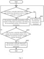
- step S301 determining whether the main controller is operating abnormally according to the state monitoring information.
- the state monitoring information includes: monitoring information in a preset period.
- the monitoring information may include: heartbeat messages, and/or state information periodically reported, and the like.
- the main controller in a normal state, is responsible for controlling the operation state of the autonomous vehicle, and the auxiliary controller is configured to monitor the operation state of the main controller.
- the main controller periodically sends monitoring information to the auxiliary controllers in a process of main controlling, so that the auxiliary controller can monitor the operation state of the main controller in each monitoring period (such as 1 second or 5 seconds). It is determined that the main controller is operating abnormally if the monitoring information received by the auxiliary controller is abnormal information or the auxiliary controller does not receive any monitoring information in the preset period.
- the state monitoring information may further include: a real-time data processing amount.
- a real-time data processing amount By monitoring the real-time data processing amount of the main controller for real-time data processing, it is possible to measure whether the main controller is in an overload operation situation, thereby determining whether the main controller is operating abnormally or not, and improving the accuracy of determining the operation state of the main controller.
- step S302 is to be performed.
- step S302 indicates that the main controller is operating normally.
- step S302 is to be performed; if it is determined that the main controller is operating normally, step S301 is to be performed continuously, and the main controller continuously controls the operation state of the autonomous vehicle.
- step S302 using the auxiliary controller to replace the main controller to control the operation state of the autonomous vehicle.
- the auxiliary controller takes over the main controller immediately to control the operation state of the autonomous vehicle by the auxiliary controller.
- the main controller by using state monitoring information to determine whether the main controller is operating abnormally, the main controller can be monitored in real time, allowing for timely identifying potential faults that may exist in the main controller.
- the auxiliary controller is used to replace the main controller to control the operation state of the autonomous vehicle, so that the auxiliary controller can fully utilize its control function to completely control the autonomous vehicle, thereby reducing the risk of out-of-control of the autonomous vehicle due to faults of the main controller. Consequently, the probability of traffic accidents during the driving of the autonomous vehicle is reduced, safety of testers on the vehicle is improved, and the autonomous vehicle is enabled to operate safely and effectively.
- determining that the main controller is operating abnormally includes: accumulating a total number of abnormal occurrences receiving no monitoring information in the preset period to obtain the accumulated number of the abnormal occurrences; and if the accumulated number of the abnormal occurrences exceeds a preset number threshold, determining that the main controller is operating abnormally.
- Fig. 4 is a schematic flowchart illustrating a method for determining monitoring information of a main controller by an auxiliary controller according to the present application.
- the method for determining the monitoring information of the main controller by the auxiliary controller includes, but is not limited to, the following steps S401 to S405.
- an auxiliary controller determines whether any monitoring information sent by a main controller is received.
- the monitoring information may include: heartbeat messages, and/or state information periodically reported, and the like.
- step S402 If no monitoring information is received by the auxiliary controller in a preset period, step S402 is to be performed; if there is any monitoring information received by the auxiliary controller in the preset period and the monitoring information is normal information, step S405 is to be performed.
- the auxiliary controller accumulates a total number of abnormal occurrences receiving no monitoring information, and obtains the accumulated number of abnormal occurrences.
- the number of abnormal occurrences may be accumulated in an arithmetic sequence mode.
- the number of abnormal occurrences may be accumulated by adding a preset value (e.g., 1 or 2, etc.) each time, so as to ensure that the accumulated number of abnormal occurrences reflects regular changes.
- the auxiliary controller determines whether the accumulated number of abnormal occurrences exceeds a preset number threshold.
- the preset number threshold may be set to a value such as 3 or 5 to set a tolerance for monitoring the main controller.
- step S404 is to be performed; and if it is determined that the accumulated number of abnormal occurrences does not exceed the preset number threshold (e.g., the accumulated number of abnormal occurrences is less than the preset number threshold), the method returns to step S401 to continue monitoring the monitoring information sent by the main controller.
- the preset number threshold e.g., the accumulated number of abnormal occurrences is greater than or equal to the preset number threshold
- the auxiliary controller determines that the main controller is operating abnormally.
- step S405 the number of abnormal occurrences is initialized.
- the number of abnormal occurrences of the state counter is initialized to an initial preset value (e.g., the initial preset value is 0).
- the auxiliary controller monitors and determines the monitoring message sent by the main controller to determine whether the main controller is operating abnormally, so that the main controller can be accurately monitored, thereby reducing the probability of the autonomous vehicle incapable of operating due to faults of the main controller.
- the acquiring state monitoring information (information obtained by monitoring the operation state of the main controller for controlling the operation of the autonomous vehicle) in step S 101 includes: receiving perception information; and determining the state monitoring information according to the perception information.
- the perception information is information fed back by a first data perception component or information fed back by a second data perception component.
- the state monitoring information includes at least one of: speed information of driving of the autonomous vehicle, angle information of driving of the autonomous vehicle, or position information of the autonomous vehicle.
- the second data perception component may be a component having the same function as the first data perception component.
- the second data perception component may replace the first data perception component to perceive environmental information around the autonomous vehicle, state information of the autonomous vehicle, spatial information where the autonomous vehicle is located, and the like.
- the main controller and/or the auxiliary controller can acquire perception information in various dimensions, thereby enriching the state monitoring information, and by using such state monitoring information to determine the operation state of the autonomous vehicle, the accuracy of determining is improved.
- the autonomous driving method further includes: acquiring auxiliary perception information after controlling the operation state of the autonomous vehicle in step S102; and updating the state monitoring information of the autonomous vehicle according to the auxiliary perception information.
- the auxiliary perception information is information fed back by an auxiliary perception component.
- the auxiliary perception component is a component configured to assist the first data perception component or the second data perception component in perceiving environmental factors.
- the auxiliary perception component may include: a weather sensor (e.g., a rain sensor, etc.), a temperature sensor, or the like.
- the state monitoring information can better represent the environment information around the autonomous vehicle, enabling the auxiliary controller to better control the autonomous vehicle so that the accuracy of controlling is improved.
- the perception information includes at least one of: environment image information, spatial information where the autonomous vehicle is located, vehicle state information, or communication information.
- the auxiliary controller or the main control can obtain diversified information, and therefore the state monitoring information of the autonomous vehicle is to be accurately determined according to the perception information, then the autonomous vehicle is to be accurately controlled, and the accuracy of operation of the autonomous vehicle is improved.
- the controlling the operation state of the autonomous vehicle in step S 102 includes: cutting off a control of the main controller over the autonomous vehicle according to a method of preemption; and controlling the operation state of the autonomous vehicle according to a risk avoidance information.
- the risk avoidance information is information determined based on abnormal information of operation of the main controller (e.g., fault information or error information of operation, etc.) and/or perception information fed back from a data perception component (e.g., the first data perception component or the second data perception component, etc.).
- the method of preemption may be achieved through a competition mode, allowing the main controller or the auxiliary controller to get a control on the autonomous vehicle. For example, if a fault occurs in the main controller, the auxiliary controller will take over the control on the autonomous vehicle, and the control on the autonomous vehicle by the main controller is cut off, so that the autonomous vehicle is controlled by only one controller (i.e., the auxiliary controller), so as to guarantee the safety of the driving of the autonomous vehicle.
- the auxiliary controller can clearly know how to control the autonomous vehicle to avoid potential dangerous situations (such as collisions between vehicles and the like), thereby enabling the auxiliary controller to control the operation state of the autonomous vehicle more accurately.
- the auxiliary controller quickly activates protective airbags on seats according to the risk avoidance information so as to ensure the safety of passenger on the vehicle.
- the auxiliary controller controls the autonomous vehicle to pull over according to the risk avoidance information so as to avoid a collision with other vehicles, thereby improving the accuracy of the autonomous vehicle for dealing with dangerous situations.
- the controlling the operation state of the autonomous vehicle according to the risk avoidance information includes: generating a control instruction according to the risk avoidance information; and sending the control instruction to an actuator so that the actuator can control the operation state of the autonomous vehicle according to the control instruction.
- the actuator is communicatively connected with the auxiliary controller and the main controller respectively.
- the actuator may be at least one of a power system component, a steering system component, or a braking system component.
- the actuator By sending the control instruction to the actuator, the actuator can identify a potential risk based on the control instruction and avoid the risk (such as keep away from obstacles), thereby improving the safety of operation of the autonomous vehicle.
- the auxiliary controller includes an auxiliary actuator and the main controller includes a master actuator;
- the cutting off the control of the main controller over the autonomous vehicle according to the method of preemption includes: cutting off the control of the main actuator over the autonomous vehicle according to the method of preemption;
- the controlling the operation state of the autonomous vehicle according to the risk avoidance information includes: controlling the auxiliary actuator to control the operation state of the autonomous vehicle according to the risk avoidance information.
- the auxiliary actuator and the main actuator are configured to control the operation state of the autonomous vehicle, in order to change or maintain the operation state of the autonomous vehicle.
- the main controller may include the first data perception component
- the auxiliary controller may include the second data perception component.
- the auxiliary controller can control the auxiliary actuator to accurately control the autonomous vehicle, thereby improving the safety of operation of the autonomous vehicle.
- Fig. 5 shows a schematic flowchart of an autonomous driving method according to the present application.
- the autonomous driving method may be applied to a main controller.
- the autonomous driving method provided in the present application may include, but is not limited to, the following steps S501 and S502.
- step S501 generating state monitoring information.
- the state monitoring information includes at least one of: a speed of driving of an autonomous vehicle, an angle of driving of the autonomous vehicle, and a driving route of the autonomous vehicle.
- the state monitoring information such as speed information, angle information and position information of the autonomous vehicle during driving can be obtained, and the state monitoring information can represent an operation situation of the autonomous vehicle, therefore the operation situation of the autonomous vehicle can be monitored during the autonomous vehicle being controlled, so that the autonomous vehicle can operate stably.
- step S502 sending the state monitoring information to an auxiliary controller, so that the auxiliary controller controls an operation state of the autonomous vehicle in response to determining that the main controller is operating abnormally according to the state monitoring information.
- the state monitoring information may be sent to the auxiliary controller at a preset time interval, so that the auxiliary controller can monitor the main controller periodically. If the auxiliary controller analyzes the received state monitoring information and determines that the main controller is operating abnormally, the auxiliary controller replaces the main controller to control the operation state of the autonomous vehicle.
- the auxiliary controller replaces the main controller to control the operation state of the autonomous vehicle, to reduce the probability of various incontrollable situations (such as brake failure, errors of control information and the like) of the autonomous vehicle, and reduce the probability of traffic accidents during the driving of the autonomous vehicle.
- the auxiliary controller replacing the main controller may include: using the auxiliary controller to complete all control functions of the main controller and keeping the main controller turned off.
- the auxiliary controller replacing the main controller may also include: using the auxiliary controller to assist the main controller to control the autonomous vehicle, in order to compensate for deficiencies of controlling the autonomous vehicle by only the main controller, thereby realizing a precise control of the autonomous vehicle.
- the operation state of the autonomous vehicle is controlled, and the state monitoring information is generated, the operation situation of the autonomous vehicle can be represented through the state monitoring information, facilitating the main controller to perform real-time and stable controlling on the autonomous vehicle; and the main controller sends the state monitoring information to the auxiliary controller, so that the auxiliary controller replaces the main controller to control the operation state of the autonomous vehicle if the auxiliary controller determines that the main controller is operating abnormally according to the state monitoring information, thereby reducing the probability of various incontrollable situations of the autonomous vehicle and reducing the probability of traffic accidents during the driving of the autonomous vehicle.
- the autonomous driving method further includes: after sending the state monitoring information to the auxiliary controller in step S502, stopping controlling the operation state of the autonomous vehicle by the main controller in response to determining that the main controller has a fault; and generating alarm information.
- the alarm information is configured to alert an operation end for operating the autonomous vehicle that the autonomous vehicle is abnormal.
- the main controller will receive shutdown information sent by the auxiliary controller, and the shutdown information is configured to inform the main controller to stop operating, so that the auxiliary controller can completely replace the main controller to control the autonomous vehicle, thereby reducing the probability of traffic accidents of the autonomous vehicle caused by the abnormality of the main controller.
- the main controller Before stopping operating, the main controller will further send the generated alarm information to the server, so that the server can know that the main controller of the autonomous vehicle has a fault, and forward the alarm information to the operation end for operating the autonomous vehicle, so as to acquire intervention information actively input from the operation end for operating the autonomous vehicle, reducing the probability of incontrollable situations (i.e., situations of out of control) of the autonomous vehicle, and improving the safety of the driving of the autonomous vehicle.
- incontrollable situations i.e., situations of out of control
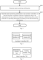
- Fig. 6 shows a structural diagram of an auxiliary controller according to the present application.
- the auxiliary controller 600 includes, but is not limited to, an acquisition module 601 and a determination module 602.
- the acquisition module 601 is configured to acquire state monitoring information, and the state monitoring information is information obtained by monitoring an operation state of a main controller.
- the determination module 602 is configured to control an operation state of an autonomous vehicle in response to determining that the main controller is operating abnormally according to the state monitoring information.
- the state monitoring information is obtained through the acquisition module 601
- the state monitoring information is obtained by monitoring the operation state of the main controller, and the main controller can be monitored in real time, so that a condition of the main controller controlling the autonomous vehicle can be obtained
- the determination module 602 can timely identify an abnormal situation of the main controller in response to determining that the main controller is operating abnormally according to the state monitoring information, allowing for a rapid intervention on the main controller, so that the auxiliary controller used currently replaces the main controller, to continue to control the operation state of the autonomous vehicle, which helps to reduce the probability of various incontrollable situations of the autonomous vehicle, and reduce the probability of traffic accidents during the driving of the autonomous vehicle, thus improving the safety of testers on the vehicle, and enabling the autonomous vehicle to operate safely and effectively.
- Fig. 7 shows a structural diagram of a main controller according to the present application.
- the main controller 700 includes, but is not limited to, a generation module 701 and a sending module 702.
- the generation module 701 is configured to generate state monitoring information.
- the state monitoring information is generated through the generation module 701, the operation situation of the autonomous vehicle can be represented through the state monitoring information, facilitating the main controller to perform real-time and stable control on the autonomous vehicle;
- the sending module 702 is configured to send the state monitoring information to the auxiliary controller, so that the auxiliary controller replaces the main controller to control the operation state of the autonomous vehicle in response to the auxiliary controller determining that the main controller is operating abnormally according to the state monitoring information, thereby reducing the probability of various incontrollable situations of the autonomous vehicle, and reducing the probability of traffic accidents during the driving of the autonomous vehicle.
- Fig. 8 shows a structural diagram of an autonomous driving system according to the present application.
- the autonomous driving system includes, but is not limited to, the followings: a main controller 801, an auxiliary controller 802, an execution device 803, and a data perception component 804 which are connected communicatively.
- the main controller 801 is configured to perform the autonomous driving method applied to the main controller according to the present application.
- the auxiliary controller 802 is configured to perform the autonomous driving method applied to the auxiliary controller according to the present application.
- the execution device 803 is configured to acquire control information sent by the main controller 801 or the auxiliary controller 802, and maintain or change an operation state of the autonomous vehicle according to the control information.
- the data perception component 804 is configured to feed perception information back to the main controller 801 or the auxiliary controller 802, so that the main controller 801 or the auxiliary controller 802 can determine state monitoring information of the autonomous vehicle according to the perception information.
- the main controller 801 is connected to the auxiliary controller 802, the data perception component 804 and the execution device 803 respectively.
- the main controller 801 is configured to control the operation state of the autonomous vehicle in a normal state, for example, the main controller 801 controls the execution device 803 to enable the autonomous vehicle to perform operations such as driving or stopping, and/or, receives perception information sent by the data perception component 804, and/or periodically sends state monitoring information (e.g., heartbeat message, etc.) to the auxiliary controller 802.
- state monitoring information e.g., heartbeat message, etc.
- the auxiliary controller 802 is configured to monitor the operation state of the main controller 801, for example, to confirm whether the main controller 801 is operating normally by monitoring heartbeat messages periodically sent by the main controller 801, and the like. If an abnormality occurs in the main controller 801, the auxiliary controller 802 takes over the control function of the main controller 801 to control the operation of the execution device 803 connected to the auxiliary controller 802. Moreover, by obtaining the perception information sent by the data perception component 804 connected to the auxiliary controller 802, the auxiliary controller 802 realizes an auxiliary control on the autonomous vehicle.
- the auxiliary controller 802 may only perform a risk avoidance operation on the autonomous vehicle. For example, if the main controller has a fault, the auxiliary controller 802 controls the autonomous vehicle (e.g., sends a control signal to the execution device 803) to safely pull over, activates relevant alarm signals (e.g., a double flashing light, etc.), and sends fault information to a server, or the like.
- the autonomous vehicle e.g., sends a control signal to the execution device 803 to safely pull over, activates relevant alarm signals (e.g., a double flashing light, etc.), and sends fault information to a server, or the like.
- the auxiliary controller 802 may be an autonomous control system with relatively simple functions, and only implements simple risk avoidance functions such as emergency braking, and/or side parking; the auxiliary controller 802 may also receive a control instruction input from external, and implement a control function on the execution device 803 according to the control instruction, so as to control the operation state of the autonomous vehicle; the auxiliary controller 802 may also be a device capable of realizing all control functions of the main controller 801, to replace the main controller 801 for controlling the autonomous vehicle.
- the execution device 803 is configured to receive control information sent by the main controller 801 or the auxiliary controller 802, to control the operation state of the autonomous vehicle. It should be noted that, after the auxiliary controller 802 takes over the control on the autonomous vehicle, the execution device 803 will no longer receive any control instruction sent by the main controller 801. In this case, the execution device 803 controls the autonomous vehicle according to the control information received from the auxiliary controller 802, so as to improve the accuracy of the control on the autonomous vehicle.
- the execution device 803 includes at least one of: a power system component, a steering system component, or a braking system component. By using the execution device 803 to control the autonomous vehicle, the operation state (e.g., moving direction, driving speed, etc.) of the autonomous vehicle may be changed or maintained.
- the data perception component 804 is configured to perceive state information of the autonomous vehicle during driving, environmental information around the autonomous vehicle, and the like.
- the data perception component 804 is communicatively connected with the main controller 801 and the auxiliary controller 802 respectively, and can provide information perceived by the data perception component 804 to the main controller 801 and the auxiliary controller 802, so that the main controller 801 and/or the auxiliary controller 802 can determine state monitoring information of the autonomous vehicle according to the perceived information, thereby realizing an autonomous control on the autonomous vehicle.
- the data perception component 804 includes, but is not limited to, at least one of: a perception element for perceiving an external environment, a perception instrument for perceiving a state of the vehicle, and a communication element.
- the perception element for perceiving the external environment may include: a camera and/or a radar; the perception instrument for perceiving the state of the vehicle may include at least one of: a gyroscope, a tachometer, an accelerometer, a steering angle sensor, a Global Positioning System (GPS) or a Beidou device; the communication element may acquire at least one of the following communication information: external communication information, information of an electronic map, real-time traffic information, or the like.
- GPS Global Positioning System
- Fig. 9 shows a structural diagram of an autonomous driving system according to the present application.
- the autonomous driving system includes, but is not limited to, the following devices including a main controller 901, an auxiliary controller 902, a first data perception component 903, a first execution device 904, a second data perception component 905, and a second execution device 906 which are connected communicatively.
- the main controller 901 has the same function as the main controller 801 shown in Fig. 8
- the auxiliary controller 902 has the same function as the auxiliary controller 802 shown in Fig. 8 .
- the first data perception component 903 and the second data perception component 905 each can realize the function of the data perception component 804 shown in Fig. 8 .
- the auxiliary controller 902 may be connected to the first data perception component 903 to obtain perception information fed back by the first data perception component 903, or , the auxiliary controller 902 may be connected to the second data perception component 905 to obtain auxiliary perception information fed back by the second data perception component 905, and the auxiliary perception information is configured to update state monitoring information of the autonomous vehicle, so that the auxiliary controller 902 can obtain more accurate operation information of the autonomous vehicle.
- the first data perception component 903 and the second data perception component 905 each may be implemented by multiple different sensors to enrich perception information of the autonomous vehicle in multiple different dimensions.
- the first execution device 904 and the second execution device 906 each can realize the function of the execution device 803 shown in Fig. 8 .
- the second execution device 906 has a higher priority than the first execution device 904.
- the first execution device 904 is in a disabled state, i.e., the first execution device 904 stops controlling the autonomous vehicle, so that the second execution device 906 can replace the first execution device 904 and perform a full control on the autonomous vehicle.
- the second data perception component 905 and the second execution device 906 can enable the auxiliary controller 902 to obtain more detailed state information and perception information during the driving of the autonomous vehicle under the situation that the autonomous vehicle is controlled by the auxiliary controller 902, so as to help the auxiliary controller 902 to better control the autonomous vehicle, which reduces the probability of various incontrollable situations (such as brake failure, errors of control information and the like) of the autonomous vehicle, reduces the probability of traffic accidents during the driving of the autonomous vehicle, and improves the accuracy of the control on the autonomous vehicle.
- various incontrollable situations such as brake failure, errors of control information and the like
- FIG. 10 is a structural diagram illustrating an exemplary hardware architecture of a computing device for implementing an autonomous driving method and devices according to the present application.
- the computing device 1000 includes an input device 1001, an input interface 1002, a central processor 1003, a memory 1004, an output interface 1005, and an output device 1006.
- the input interface 1002, the central processor 1003, the memory 1004, and the output interface 1005 are connected to each other through a bus 1007, and the input device 1001 and the output device 1006 are connected to the bus 1007 through the input interface 1002 and the output interface 1005, respectively, and then connected to other components of the computing device 1000.
- the input device 1001 receives input information from outside, and transmits the input information to the central processor 1003 through the input interface 1002; the central processor 1003 processes the input information based on computer-executable instructions stored in the memory 1004 to generate output information, temporarily or permanently stores the output information in the memory 1004, and then transfers the output information to the output device 1006 through the output interface 1005; the output device 1006 outputs the output information to an exterior of the computing device 1000 to be used.
- the computing device shown in Fig. 10 may be implemented as an electronic device, which may include: a memory configured to store a computer program; and a processor configured to execute the computer program stored in the memory to perform the above-described autonomous driving method.
- the present application further provides a computer-readable storage medium storing a computer program thereon, the computer program, when executed by a processor, causes the processor to implement the above-described autonomous driving method.
- the embodiments/implementations of the present application may be implemented by a data processor of a mobile device executing computer program instructions, for example in a processor entity, or by hardware, or by a combination of software and hardware.
- the computer program instructions may be assembly instructions, instruction set architecture (ISA) instructions, machine-related instructions, microcode, firmware instructions, state setting data, or source or object code written in any combination of one or more programming languages.
- the block diagrams of any logic flows in the figures of the present application may represent program steps, or may represent interconnected logic circuits, modules, and functions, or may represent a combination of program steps and logic circuits, modules, and functions.
- the computer program may be stored in the memory.
- the memory may be of any type suitable to the local technical environment and may be implemented by using any suitable data storage technology, such as, but not limited to, Read Only Memory (ROM), Random Access Memory (RAM), optical storage devices and systems (digital versatile disks, DVDs or CD disks), or the like.
- the computer readable medium may include a non-transitory storage medium.
- the data processor may be of any type suitable to the local technical environment, such as, but not limited to, general purpose computers, special purpose computers, microprocessors, Digital Signal Processors (DSPs), Application Specific Integrated Circuits (ASICs), programmable logic devices (FGPAs), and processors based on a multi-core processor architecture.
- DSPs Digital Signal Processors
- ASICs Application Specific Integrated Circuits
- FGPAs programmable logic devices
Landscapes
- Engineering & Computer Science (AREA)
- Automation & Control Theory (AREA)
- Transportation (AREA)
- Mechanical Engineering (AREA)
- Human Computer Interaction (AREA)
- Physics & Mathematics (AREA)
- Mathematical Physics (AREA)
- Traffic Control Systems (AREA)
- Safety Devices In Control Systems (AREA)
- Control Of Driving Devices And Active Controlling Of Vehicle (AREA)
- Debugging And Monitoring (AREA)
Applications Claiming Priority (2)
| Application Number | Priority Date | Filing Date | Title |
|---|---|---|---|
| CN202210434520.8A CN116968754A (zh) | 2022-04-24 | 2022-04-24 | 自动驾驶方法、控制器和系统 |
| PCT/CN2023/089186 WO2023207701A1 (zh) | 2022-04-24 | 2023-04-19 | 自动驾驶方法和系统、控制器、电子设备和计算机存储介质 |
Publications (2)
| Publication Number | Publication Date |
|---|---|
| EP4477488A1 true EP4477488A1 (de) | 2024-12-18 |
| EP4477488A4 EP4477488A4 (de) | 2026-01-07 |
Family
ID=88475415
Family Applications (1)
| Application Number | Title | Priority Date | Filing Date |
|---|---|---|---|
| EP23795134.8A Pending EP4477488A4 (de) | 2022-04-24 | 2023-04-19 | Autonomes antriebsverfahren und -system sowie steuerungen, elektronische vorrichtung und computerspeichermedium |
Country Status (6)
| Country | Link |
|---|---|
| US (1) | US20250178619A1 (de) |
| EP (1) | EP4477488A4 (de) |
| JP (1) | JP7783994B2 (de) |
| KR (1) | KR20240075945A (de) |
| CN (1) | CN116968754A (de) |
| WO (1) | WO2023207701A1 (de) |
Families Citing this family (2)
| Publication number | Priority date | Publication date | Assignee | Title |
|---|---|---|---|---|
| CN117842076A (zh) * | 2023-12-28 | 2024-04-09 | 岚图汽车科技有限公司 | 自动驾驶感知冗余控制方法、装置、设备及存储介质 |
| CN118701105A (zh) * | 2024-06-28 | 2024-09-27 | 中国第一汽车股份有限公司 | 车辆自动驾驶中的控制方法、装置、设备以及存储介质 |
Family Cites Families (28)
| Publication number | Priority date | Publication date | Assignee | Title |
|---|---|---|---|---|
| JP3866536B2 (ja) | 2001-06-27 | 2007-01-10 | 株式会社デンソー | 車両の自動運転システム |
| JP2003077100A (ja) * | 2001-09-03 | 2003-03-14 | Denso Corp | 異常検出装置、自動運転システム、異常検出方法 |
| JP4848027B2 (ja) | 2004-01-30 | 2011-12-28 | 日立オートモティブシステムズ株式会社 | 車両制御装置 |
| JP5569752B2 (ja) | 2011-12-08 | 2014-08-13 | 株式会社デンソー | 電子制御装置、および、これを用いた電動パワーステアリング装置 |
| JP6801287B2 (ja) | 2016-08-10 | 2020-12-16 | 株式会社ジェイテクト | モータ制御装置 |
| CN107894949A (zh) * | 2017-10-11 | 2018-04-10 | 五八有限公司 | 异常处理的方法、装置及设备 |
| DE102017010716A1 (de) * | 2017-11-10 | 2019-05-16 | Knorr-Bremse Systeme für Nutzfahrzeuge GmbH | System zum wenigstens teilautonomen Betrieb eines Kraftfahrzeugs mit doppelter Redundanz |
| WO2019106664A1 (en) * | 2017-11-28 | 2019-06-06 | Israel Aerospace Industries Ltd. | Failure detection in an autonomous vehicle |
| JP6798476B2 (ja) | 2017-11-30 | 2020-12-09 | 株式会社デンソー | モータ制御装置、モータ駆動システム、及び、モータ制御方法 |
| CN108196547B (zh) * | 2018-01-08 | 2020-06-23 | 北京图森未来科技有限公司 | 一种自动驾驶系统 |
| WO2019176299A1 (ja) * | 2018-03-13 | 2019-09-19 | 日立オートモティブシステムズ株式会社 | 車両搭載機器の制御装置 |
| KR102033559B1 (ko) | 2018-05-08 | 2019-10-17 | 주식회사 만도 | 조향 제어 장치 및 방법과, 조향 장치 |
| CN109367544B (zh) * | 2018-09-07 | 2021-01-05 | 百度在线网络技术(北京)有限公司 | 自动驾驶车辆控制方法、装置及存储介质 |
| US12530970B2 (en) * | 2018-12-26 | 2026-01-20 | Zoox, Inc. | Collision avoidance system |
| US10802942B2 (en) * | 2018-12-28 | 2020-10-13 | Intel Corporation | Methods and apparatus to detect anomalies of a monitored system |
| US11176007B2 (en) * | 2019-04-12 | 2021-11-16 | Ghost Locomotion Inc. | Redundant processing fabric for autonomous vehicles |
| US11068295B2 (en) * | 2019-04-12 | 2021-07-20 | Ghost Locomotion Inc. | Device operation across multiple operating system modalities |
| EP3778309B1 (de) | 2019-08-15 | 2022-04-13 | Apollo Intelligent Driving Technology (Beijing) Co., Ltd. | Autonomes fahrzeug und system für autonomes fahrzeug |
| JP7097866B2 (ja) | 2019-09-24 | 2022-07-08 | 本田技研工業株式会社 | 遠隔駐車システム |
| JP7094255B2 (ja) | 2019-09-24 | 2022-07-01 | 本田技研工業株式会社 | 車両制御システム |
| CN110533947A (zh) * | 2019-10-14 | 2019-12-03 | 北京百度网讯科技有限公司 | 交通工具的控制系统、方法、电子设备和计算机存储介质 |
| KR20210073705A (ko) * | 2019-12-10 | 2021-06-21 | 현대모비스 주식회사 | 자율주행차량의 고장에 따른 차량 제어 시스템 및 방법 |
| CN113247022A (zh) * | 2021-06-23 | 2021-08-13 | 智己汽车科技有限公司 | 一种自动驾驶冗余控制系统及方法 |
| CN113721614A (zh) * | 2021-08-26 | 2021-11-30 | 东风悦享科技有限公司 | 一种集成北斗导航高性能自动驾驶控域制器、系统及其车辆 |
| CN113635919B (zh) * | 2021-09-06 | 2022-12-09 | 北京百度网讯科技有限公司 | 控制执行器的方法、装置、设备以及自动驾驶车辆 |
| CN113619576B (zh) * | 2021-09-07 | 2022-08-12 | 阿波罗智能技术(北京)有限公司 | 车辆控制方法、装置、设备、存储介质及自动驾驶车辆 |
| CN113734201B (zh) * | 2021-09-22 | 2023-05-09 | 中国第一汽车股份有限公司 | 车辆冗余控制方法、装置、电子设备及介质 |
| CN113696903A (zh) * | 2021-09-28 | 2021-11-26 | 国汽(北京)智能网联汽车研究院有限公司 | 一种车辆控制方法、装置、电子设备及存储介质 |
-
2022
- 2022-04-24 CN CN202210434520.8A patent/CN116968754A/zh active Pending
-
2023
- 2023-04-19 JP JP2024538758A patent/JP7783994B2/ja active Active
- 2023-04-19 US US18/843,291 patent/US20250178619A1/en active Pending
- 2023-04-19 EP EP23795134.8A patent/EP4477488A4/de active Pending
- 2023-04-19 KR KR1020247016517A patent/KR20240075945A/ko active Pending
- 2023-04-19 WO PCT/CN2023/089186 patent/WO2023207701A1/zh not_active Ceased
Also Published As
| Publication number | Publication date |
|---|---|
| CN116968754A (zh) | 2023-10-31 |
| JP7783994B2 (ja) | 2025-12-10 |
| US20250178619A1 (en) | 2025-06-05 |
| WO2023207701A1 (zh) | 2023-11-02 |
| EP4477488A4 (de) | 2026-01-07 |
| JP2025501147A (ja) | 2025-01-17 |
| KR20240075945A (ko) | 2024-05-29 |
Similar Documents
| Publication | Publication Date | Title |
|---|---|---|
| JP7354343B2 (ja) | 自動運転システム、故障警報方法及び機器 | |
| US12391277B2 (en) | Autonomous driving system | |
| CN109367544B (zh) | 自动驾驶车辆控制方法、装置及存储介质 | |
| US10102696B2 (en) | In-vehicle control device and in-vehicle recording system | |
| EP4235333B1 (de) | Fehlertolerante steuerung eines autonomen fahrzeugs mit mehreren steuerungsspuren | |
| EP4477488A1 (de) | Autonomes antriebsverfahren und -system sowie steuerungen, elektronische vorrichtung und computerspeichermedium | |
| US10940867B2 (en) | Substitution of sensor measurement data | |
| US9174649B1 (en) | Redundancy for automated vehicle operations | |
| US10890908B2 (en) | Vehicle control system and action plan system provided with same | |
| CN110737192A (zh) | 汽车驾驶冗余控制系统及其方法 | |
| US9971349B2 (en) | Method and device for monitoring a system of a vehicle which provides an at least partially automated driving function | |
| US20210086792A1 (en) | Method of assisting a motor vehicle | |
| US20210237770A1 (en) | Vehicle control apparatus | |
| EP3677476A1 (de) | Fahrzeugmontierte vorrichtung und verfahren zur unfallüberwachung | |
| WO2021035701A1 (zh) | 一种传感器检测方法及车载控制终端 | |
| US20210090440A1 (en) | Method for assisting a motor vehicle | |
| AU2022209302A1 (en) | Simulation method for autonomous vehicle and method for controlling autonomous vehicle | |
| US20240331537A1 (en) | Method for the infrastructure-supported assistance of multiple motor vehicles | |
| CN113173136A (zh) | 车辆控制装置和记录介质 | |
| EP3697662B1 (de) | Verfahren zur fehlerdiagnose eines ego-fahrzeugs und/oder eines umgebenden fahrzeugs | |
| US20240010243A1 (en) | Device for infrastructure-supported assistance of a motor vehicle | |
| CN214504177U (zh) | 汽车驾驶控制装置、设备及汽车设备 | |
| CN110588669A (zh) | 用于在故障车辆中执行最小风险操纵的方法和控制单元 | |
| US20240174263A1 (en) | Vehicle control system | |
| JP7782073B2 (ja) | 車両制御装置 |
Legal Events
| Date | Code | Title | Description |
|---|---|---|---|
| STAA | Information on the status of an ep patent application or granted ep patent |
Free format text: STATUS: THE INTERNATIONAL PUBLICATION HAS BEEN MADE |
|
| PUAI | Public reference made under article 153(3) epc to a published international application that has entered the european phase |
Free format text: ORIGINAL CODE: 0009012 |
|
| STAA | Information on the status of an ep patent application or granted ep patent |
Free format text: STATUS: REQUEST FOR EXAMINATION WAS MADE |
|
| 17P | Request for examination filed |
Effective date: 20240912 |
|
| AK | Designated contracting states |
Kind code of ref document: A1 Designated state(s): AL AT BE BG CH CY CZ DE DK EE ES FI FR GB GR HR HU IE IS IT LI LT LU LV MC ME MK MT NL NO PL PT RO RS SE SI SK SM TR |
|
| DAV | Request for validation of the european patent (deleted) | ||
| DAX | Request for extension of the european patent (deleted) | ||
| A4 | Supplementary search report drawn up and despatched |
Effective date: 20251208 |
|
| RIC1 | Information provided on ipc code assigned before grant |
Ipc: B60W 50/00 20060101AFI20251202BHEP Ipc: B60W 50/023 20120101ALI20251202BHEP Ipc: B60W 50/02 20120101ALI20251202BHEP Ipc: B60W 60/00 20200101ALI20251202BHEP Ipc: B60W 50/029 20120101ALN20251202BHEP |