EP4235333B1 - Fehlertolerante steuerung eines autonomen fahrzeugs mit mehreren steuerungsspuren - Google Patents
Fehlertolerante steuerung eines autonomen fahrzeugs mit mehreren steuerungsspuren Download PDFInfo
- Publication number
- EP4235333B1 EP4235333B1 EP23178010.7A EP23178010A EP4235333B1 EP 4235333 B1 EP4235333 B1 EP 4235333B1 EP 23178010 A EP23178010 A EP 23178010A EP 4235333 B1 EP4235333 B1 EP 4235333B1
- Authority
- EP
- European Patent Office
- Prior art keywords
- vehicle
- control
- lane
- fault
- control system
- Prior art date
- Legal status (The legal status is an assumption and is not a legal conclusion. Google has not performed a legal analysis and makes no representation as to the accuracy of the status listed.)
- Active
Links
Images


Classifications
-
- G—PHYSICS
- G05—CONTROLLING; REGULATING
- G05D—SYSTEMS FOR CONTROLLING OR REGULATING NON-ELECTRIC VARIABLES
- G05D1/00—Control of position, course, altitude or attitude of land, water, air or space vehicles, e.g. using automatic pilots
- G05D1/0055—Control of position, course, altitude or attitude of land, water, air or space vehicles, e.g. using automatic pilots with safety arrangements
- G05D1/0077—Control of position, course, altitude or attitude of land, water, air or space vehicles, e.g. using automatic pilots with safety arrangements using redundant signals or controls
-
- B—PERFORMING OPERATIONS; TRANSPORTING
- B60—VEHICLES IN GENERAL
- B60W—CONJOINT CONTROL OF VEHICLE SUB-UNITS OF DIFFERENT TYPE OR DIFFERENT FUNCTION; CONTROL SYSTEMS SPECIALLY ADAPTED FOR HYBRID VEHICLES; ROAD VEHICLE DRIVE CONTROL SYSTEMS FOR PURPOSES NOT RELATED TO THE CONTROL OF A PARTICULAR SUB-UNIT
- B60W50/00—Details of control systems for road vehicle drive control not related to the control of a particular sub-unit, e.g. process diagnostic or vehicle driver interfaces
- B60W50/02—Ensuring safety in case of control system failures, e.g. by diagnosing, circumventing or fixing failures
- B60W50/023—Avoiding failures by using redundant parts
-
- B—PERFORMING OPERATIONS; TRANSPORTING
- B60—VEHICLES IN GENERAL
- B60W—CONJOINT CONTROL OF VEHICLE SUB-UNITS OF DIFFERENT TYPE OR DIFFERENT FUNCTION; CONTROL SYSTEMS SPECIALLY ADAPTED FOR HYBRID VEHICLES; ROAD VEHICLE DRIVE CONTROL SYSTEMS FOR PURPOSES NOT RELATED TO THE CONTROL OF A PARTICULAR SUB-UNIT
- B60W50/00—Details of control systems for road vehicle drive control not related to the control of a particular sub-unit, e.g. process diagnostic or vehicle driver interfaces
- B60W50/02—Ensuring safety in case of control system failures, e.g. by diagnosing, circumventing or fixing failures
- B60W50/029—Adapting to failures or work around with other constraints, e.g. circumvention by avoiding use of failed parts
-
- B—PERFORMING OPERATIONS; TRANSPORTING
- B60—VEHICLES IN GENERAL
- B60W—CONJOINT CONTROL OF VEHICLE SUB-UNITS OF DIFFERENT TYPE OR DIFFERENT FUNCTION; CONTROL SYSTEMS SPECIALLY ADAPTED FOR HYBRID VEHICLES; ROAD VEHICLE DRIVE CONTROL SYSTEMS FOR PURPOSES NOT RELATED TO THE CONTROL OF A PARTICULAR SUB-UNIT
- B60W60/00—Drive control systems specially adapted for autonomous road vehicles
- B60W60/001—Planning or execution of driving tasks
- B60W60/0015—Planning or execution of driving tasks specially adapted for safety
- B60W60/0016—Planning or execution of driving tasks specially adapted for safety of the vehicle or its occupants
-
- B—PERFORMING OPERATIONS; TRANSPORTING
- B60—VEHICLES IN GENERAL
- B60W—CONJOINT CONTROL OF VEHICLE SUB-UNITS OF DIFFERENT TYPE OR DIFFERENT FUNCTION; CONTROL SYSTEMS SPECIALLY ADAPTED FOR HYBRID VEHICLES; ROAD VEHICLE DRIVE CONTROL SYSTEMS FOR PURPOSES NOT RELATED TO THE CONTROL OF A PARTICULAR SUB-UNIT
- B60W60/00—Drive control systems specially adapted for autonomous road vehicles
- B60W60/001—Planning or execution of driving tasks
- B60W60/0015—Planning or execution of driving tasks specially adapted for safety
- B60W60/0018—Planning or execution of driving tasks specially adapted for safety by employing degraded modes, e.g. reducing speed, in response to suboptimal conditions
- B60W60/00186—Planning or execution of driving tasks specially adapted for safety by employing degraded modes, e.g. reducing speed, in response to suboptimal conditions related to the vehicle
-
- G—PHYSICS
- G01—MEASURING; TESTING
- G01C—MEASURING DISTANCES, LEVELS OR BEARINGS; SURVEYING; NAVIGATION; GYROSCOPIC INSTRUMENTS; PHOTOGRAMMETRY OR VIDEOGRAMMETRY
- G01C21/00—Navigation; Navigational instruments not provided for in groups G01C1/00 - G01C19/00
- G01C21/10—Navigation; Navigational instruments not provided for in groups G01C1/00 - G01C19/00 by using measurements of speed or acceleration
- G01C21/12—Navigation; Navigational instruments not provided for in groups G01C1/00 - G01C19/00 by using measurements of speed or acceleration executed aboard the object being navigated; Dead reckoning
- G01C21/16—Navigation; Navigational instruments not provided for in groups G01C1/00 - G01C19/00 by using measurements of speed or acceleration executed aboard the object being navigated; Dead reckoning by integrating acceleration or speed, i.e. inertial navigation
- G01C21/165—Navigation; Navigational instruments not provided for in groups G01C1/00 - G01C19/00 by using measurements of speed or acceleration executed aboard the object being navigated; Dead reckoning by integrating acceleration or speed, i.e. inertial navigation combined with non-inertial navigation instruments
- G01C21/1652—Navigation; Navigational instruments not provided for in groups G01C1/00 - G01C19/00 by using measurements of speed or acceleration executed aboard the object being navigated; Dead reckoning by integrating acceleration or speed, i.e. inertial navigation combined with non-inertial navigation instruments with ranging devices, e.g. LIDAR or RADAR
-
- G—PHYSICS
- G05—CONTROLLING; REGULATING
- G05D—SYSTEMS FOR CONTROLLING OR REGULATING NON-ELECTRIC VARIABLES
- G05D1/00—Control of position, course, altitude or attitude of land, water, air or space vehicles, e.g. using automatic pilots
- G05D1/20—Control system inputs
- G05D1/24—Arrangements for determining position or orientation
- G05D1/247—Arrangements for determining position or orientation using signals provided by artificial sources external to the vehicle, e.g. navigation beacons
-
- G—PHYSICS
- G05—CONTROLLING; REGULATING
- G05D—SYSTEMS FOR CONTROLLING OR REGULATING NON-ELECTRIC VARIABLES
- G05D1/00—Control of position, course, altitude or attitude of land, water, air or space vehicles, e.g. using automatic pilots
- G05D1/80—Arrangements for reacting to or preventing system or operator failure
- G05D1/87—Arrangements for reacting to or preventing system or operator failure using redundant control arrangements
-
- G—PHYSICS
- G06—COMPUTING OR CALCULATING; COUNTING
- G06F—ELECTRIC DIGITAL DATA PROCESSING
- G06F11/00—Error detection; Error correction; Monitoring
- G06F11/07—Responding to the occurrence of a fault, e.g. fault tolerance
- G06F11/16—Error detection or correction of the data by redundancy in hardware
- G06F11/20—Error detection or correction of the data by redundancy in hardware using active fault-masking, e.g. by switching out faulty elements or by switching in spare elements
- G06F11/202—Error detection or correction of the data by redundancy in hardware using active fault-masking, e.g. by switching out faulty elements or by switching in spare elements where processing functionality is redundant
- G06F11/2023—Failover techniques
- G06F11/2025—Failover techniques using centralised failover control functionality
-
- G—PHYSICS
- G06—COMPUTING OR CALCULATING; COUNTING
- G06F—ELECTRIC DIGITAL DATA PROCESSING
- G06F11/00—Error detection; Error correction; Monitoring
- G06F11/07—Responding to the occurrence of a fault, e.g. fault tolerance
- G06F11/16—Error detection or correction of the data by redundancy in hardware
- G06F11/20—Error detection or correction of the data by redundancy in hardware using active fault-masking, e.g. by switching out faulty elements or by switching in spare elements
- G06F11/202—Error detection or correction of the data by redundancy in hardware using active fault-masking, e.g. by switching out faulty elements or by switching in spare elements where processing functionality is redundant
- G06F11/2023—Failover techniques
- G06F11/2028—Failover techniques eliminating a faulty processor or activating a spare
-
- G—PHYSICS
- G06—COMPUTING OR CALCULATING; COUNTING
- G06F—ELECTRIC DIGITAL DATA PROCESSING
- G06F11/00—Error detection; Error correction; Monitoring
- G06F11/07—Responding to the occurrence of a fault, e.g. fault tolerance
- G06F11/16—Error detection or correction of the data by redundancy in hardware
- G06F11/20—Error detection or correction of the data by redundancy in hardware using active fault-masking, e.g. by switching out faulty elements or by switching in spare elements
- G06F11/202—Error detection or correction of the data by redundancy in hardware using active fault-masking, e.g. by switching out faulty elements or by switching in spare elements where processing functionality is redundant
- G06F11/2038—Error detection or correction of the data by redundancy in hardware using active fault-masking, e.g. by switching out faulty elements or by switching in spare elements where processing functionality is redundant with a single idle spare processing component
-
- G—PHYSICS
- G06—COMPUTING OR CALCULATING; COUNTING
- G06F—ELECTRIC DIGITAL DATA PROCESSING
- G06F11/00—Error detection; Error correction; Monitoring
- G06F11/07—Responding to the occurrence of a fault, e.g. fault tolerance
- G06F11/16—Error detection or correction of the data by redundancy in hardware
- G06F11/20—Error detection or correction of the data by redundancy in hardware using active fault-masking, e.g. by switching out faulty elements or by switching in spare elements
- G06F11/202—Error detection or correction of the data by redundancy in hardware using active fault-masking, e.g. by switching out faulty elements or by switching in spare elements where processing functionality is redundant
- G06F11/2041—Error detection or correction of the data by redundancy in hardware using active fault-masking, e.g. by switching out faulty elements or by switching in spare elements where processing functionality is redundant with more than one idle spare processing component
-
- B—PERFORMING OPERATIONS; TRANSPORTING
- B60—VEHICLES IN GENERAL
- B60W—CONJOINT CONTROL OF VEHICLE SUB-UNITS OF DIFFERENT TYPE OR DIFFERENT FUNCTION; CONTROL SYSTEMS SPECIALLY ADAPTED FOR HYBRID VEHICLES; ROAD VEHICLE DRIVE CONTROL SYSTEMS FOR PURPOSES NOT RELATED TO THE CONTROL OF A PARTICULAR SUB-UNIT
- B60W50/00—Details of control systems for road vehicle drive control not related to the control of a particular sub-unit, e.g. process diagnostic or vehicle driver interfaces
- B60W50/02—Ensuring safety in case of control system failures, e.g. by diagnosing, circumventing or fixing failures
- B60W50/029—Adapting to failures or work around with other constraints, e.g. circumvention by avoiding use of failed parts
- B60W2050/0292—Fail-safe or redundant systems, e.g. limp-home or backup systems
-
- G—PHYSICS
- G06—COMPUTING OR CALCULATING; COUNTING
- G06F—ELECTRIC DIGITAL DATA PROCESSING
- G06F2201/00—Indexing scheme relating to error detection, to error correction, and to monitoring
- G06F2201/81—Threshold
Definitions
- the present invention relates generally to autonomous vehicles and, more particularly, the systems and methods for controlling an autonomous vehicle that has multiple control lanes.
- An autonomous vehicle is a vehicle that is capable of sensing its environment and navigating without human input.
- an autonomous vehicle can observe its surrounding environment using a variety of sensors and can attempt to comprehend the environment by performing various processing techniques on data collected by the sensors. Given knowledge of its surrounding environment, the autonomous vehicle can identify an appropriate motion plan through such surrounding environment and command vehicle motion to track such motion plan.
- US 2015/012166 A1 relates to a method for operating a motor vehicle in an automated driving mode that includes identifying, using two devices, the current position, the objects and open spaces currently present in the vehicle surroundings.
- US 2015/012166 A1 further comprises respectively identifying, by the two devices, a trajectory for independent vehicle guidance; and in two regulation devices, control signals for actuator devices are respectively identified and control is applied, in accordance with the previously calculated trajectory, to longitudinal-dynamics-influencing actuators and to transverse-dynamics-influencing actuators for vehicle control.
- US 2016/0368491 A1 relates to a method and a device for operating a motor vehicle in an automated driving mode, in which a standard trajectory is ascertained which implements a vehicle control according to the destination setting specified by the driver and the current environment situation, and a safety trajectory is ascertained which implements safe stopping of the vehicle in the event of an emergency as a function of the current vehicle environment situation,
- Example aspects of the present invention are directed to controlling an autonomous vehicle with multiple control lanes.
- An autonomous vehicle can autonomously navigate through a surrounding environment by executing one or more planned trajectories in a motion plan that cause the autonomous vehicle to travel along a vehicle route.
- An autonomous driving system onboard the autonomous vehicle can generate the motion plan and provide the motion plan to a vehicle control system.
- the vehicle control system can generate one or more vehicle control signals based on the motion plan to track the one or more planned trajectories, and provide the vehicle control signals to one or more vehicle actuation systems that can control the autonomous vehicle.
- the autonomous vehicle can detect a fault with respect to its operation, and in particular an operation of the autonomous driving system, vehicle control system, and/or vehicle actuation system(s).
- the autonomous vehicle can be unable to effectively handle the fault.
- an autonomous vehicle detects a fault associated with a braking control system causing a loss of braking control when the autonomous vehicle is traveling at high speed, then the autonomous vehicle can be unable to effectively slow down.
- the autonomous vehicle could downshift to slow down, but this may not be the most "effective" solution.
- the autonomous vehicle detects a fault associated with a transmission system, then downshifting may not be an available solution.
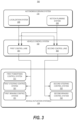
- an autonomous vehicle can include a vehicle computing system that implements a variety of systems on-board the autonomous vehicle (e.g., located on or within the autonomous vehicle) for autonomous navigation.
- the vehicle computing system can include an autonomous driving system (e.g., for planning and executing autonomous navigation), a plurality of vehicle actuation systems (e.g., vehicle-specific systems responsible for powertrain, steering, braking, etc.), and a vehicle control system (e.g., for interfacing between the autonomous driving system and vehicle-specific vehicle actuation systems).
- the vehicle computing system can include a collision mitigation system (e.g., for detecting and mitigating potential collisions).
- the autonomous driving system of the autonomous vehicle can include one or more autonomy system(s) for planning and executing autonomous navigation.
- an autonomous driving system can include, among other systems, a localization system, a perception system, a prediction system, and a motion planning system that cooperate to perceive a surrounding environment of an autonomous vehicle and determine a motion plan for controlling a motion of the autonomous vehicle.
- the motion plan can include one or more trajectories (e.g., trajectory information) that cause the autonomous vehicle to travel from a starting location of a vehicle route to an ending location of the vehicle route when executed.
- the trajectory information can include requirements on speed, time of arrival, or other components of the vehicle's dynamic state associated with the vehicle route.
- the motion plan can include one or more primary trajectories that each correspond to a segment of the vehicle route and cause the autonomous vehicle to travel from the starting location to the ending location of the vehicle route when executed in sequence.
- Each of the one or more primary trajectories can cause the autonomous vehicle to travel from a starting location of the primary trajectory (e.g., starting location of the corresponding vehicle route segment) to an ending location of the primary trajectory (e.g., ending location of the corresponding vehicle route segment) when executed.
- the motion plan can include a safe-stop trajectory associated with each primary trajectory that cause the autonomous vehicle to travel from a starting location of the primary trajectory to a safe-stop location (e.g., nearest location where the autonomous vehicle can safely come to a stop) when executed.
- the autonomous driving system can continuously update the motion plan and provide the updated motion plan to the vehicle control system.
- the autonomous driving system can update the motion plan based on the surrounding environment of the autonomous vehicle (e.g., one or more objects in the surrounding environment) and a dynamic state of the autonomous vehicle within the environment.
- the vehicle control system of the autonomous vehicle can receive data representing a motion plan from the autonomous driving system and implement the motion plan via a multi-lane control architecture.
- the vehicle control system can receive the data representing the motion plan via a plurality of control lanes.
- Each of the control lanes can be configured to independently implement the motion plan by generating one or more vehicle control signals to track a trajectory in the motion plan.
- the vehicle control system can control one or more control lanes from the plurality of control lanes to provide the vehicle control signal(s) to one or more vehicle actuation systems associated with the control lane to control the autonomous vehicle in accordance with the motion plan.
- the vehicle control system can silence one or more remaining control lanes from the plurality of control lanes by controlling the remaining control lane(s) to assume a "fail silent" mode that prevents the remaining control lane(s) from providing the vehicle control signal(s) to one or more vehicle actuation systems associated with the control lane. In this way, the vehicle control system can preclude multiple control lanes from attempting to simultaneously control a single operation of the autonomous vehicle (e.g., propulsion, steering, braking, etc.).
- the autonomous vehicle e.g., propulsion, steering, braking, etc.
- each control lane of vehicle control system can be connected to a set of vehicle actuation systems to control the autonomous vehicle independently of each other.
- a first control lane can be associated with a first set of vehicle actuation systems (e.g., systems responsible for powertrain, steering, braking, etc.) and a second control lane can be associated with a second set of vehicle actuation systems (e.g., systems responsible for powertrain, steering, braking, etc.).
- the vehicle control system can control the first control lane to implement the motion plan and provide vehicle control signal(s) to the first set of vehicle actuation systems to control the vehicle. If the vehicle control system detects a fault associated with implementing the motion plan via the first control lane, then the vehicle control system can silence the first control lane and control the second control lane to implement the motion plan.
- the vehicle control system If the vehicle control system detects a fault associated with implementing the motion plan via the first control lane, then the vehicle control system silences the first control lane and controls the second control lane to implement the motion plan.
- the vehicle control system determines that the second control lane has a reduced capability of controlling the autonomous vehicle (e.g., because the second set of vehicle actuation systems does not include a powertrain control system) and adjusts the motion plan of the autonomous vehicle accordingly.
- the vehicle control system can request the autonomous driving system to provide a new motion plan for safely stopping the autonomous vehicle (e.g., assisted safe-stop action) and implement the new motion plan.
- the vehicle control system can retrieve a locally stored safe-stop trajectory that was previously received, and track the local safe-stop trajectory.
- the vehicle actuation systems of the autonomous vehicle can include one or more systems for controlling the autonomous vehicle.
- the vehicle actuation systems can include a powertrain control system, steering control system, braking control system, etc., to control a motion of the autonomous vehicle.
- the vehicle actuation systems can also include various other systems to control different operations of the autonomous vehicle, such as, for example, a climate control system, stereo control system, seat control system, internal/external indicator control system, etc.
- the vehicle actuation systems can receive one or more vehicle control signals from a control lane of the vehicle control system, and control the autonomous vehicle in accordance with the vehicle control signals.
- the powertrain control system can control a propulsion of the autonomous vehicle
- the steering control system can control a steering of the autonomous vehicle
- the braking control system can control a braking of the autonomous vehicle
- the vehicle actuation systems can generate one or more actuator commands (e.g., at least one lateral vehicle actuator command and at least one longitudinal vehicle actuator command) and control one or more vehicle actuators in accordance with the vehicle control signals.
- Vehicle actuators can include, for example, a steering actuator, a braking actuator, and/or a propulsion actuator.
- the vehicle actuators can include further low-level control logic. For example, additional low-level control logic may be beneficial to control a steering motor to keep the steering rack at a desired position as commanded by the vehicle actuation system in case the vehicle actuation system does not directly control the steering motor.
- the vehicle actuation systems can include two or more identical sets of vehicle actuation systems. Each set of vehicle actuation systems can be connected to a control lane of the vehicle control system.
- a first set of vehicle actuation systems can include a first powertrain control system, first steering control system, first braking control system, etc.
- a second set of vehicle actuation systems can include a second powertrain control system, second steering control system, second braking control system, etc.
- the first set of vehicle actuation systems can be connected to a first control lane of the vehicle control system
- the second set of vehicle actuation systems can be connected to a second control lane of the vehicle control system.
- the vehicle actuation systems can include two or more different sets of vehicle actuation systems such that a first set of vehicle actuation systems contains a different number of and/or combination of types of control systems than a second set of vehicle actuation systems.
- Each set of vehicle actuation systems can be connected to a control lane of the vehicle control system.
- a first set of vehicle actuation systems can include a powertrain control system, first steering control system, first braking control system, etc.
- a second set of vehicle actuation systems can include a second steering control system, second braking control system, etc., but not a second powertrain control system.
- the first set of vehicle actuation systems can be connected to a first control lane of the vehicle control system
- the second set of vehicle actuation systems can be connected to a second control lane of the vehicle control system.
- the vehicle actuation systems can include independent control systems which can be connected to the same control lane of the vehicle control system.
- a first control lane can be connected to a first braking control system and a second braking control system
- a second control lane can be connected to the first braking control system and/or the second braking control system.
- the vehicle computing system can detect one or more faults associated with one or more operations of the autonomous vehicle (e.g., determining a motion plan, implementing a motion plan, etc.).
- the one or more faults can be associated with one or more of the various systems implemented by the vehicle computing system on-board the autonomous vehicle (e.g., autonomy computing system, vehicle control system, vehicle actuation system, etc.).
- the one or more various systems on-board the autonomous vehicle can each detect one or more faults associated with itself, and notify one or more other systems about the detected fault(s).
- the autonomous driving system or one of the vehicle actuation systems can detect one or more faults associated with it and provide one or more diagnostic signals to the vehicle control system to notify the vehicle control system about the detected fault(s).
- each control lane of the vehicle control system can detect one or more faults associated with it and notify the vehicle control system about the detected fault(s).
- the one or more various systems on-board the autonomous vehicle can detect one or more faults associated with each other. As an example, if the vehicle control system fails to receive a motion plan (or updated motion plan) from the autonomous driving system within a predetermined time frame, or if the vehicle control system receives a motion plan that fails a cyclic redundancy check (CRC), then the vehicle control system can determine that the autonomous driving system has experienced a fault. As another example, if the vehicle control system fails to receive a handshake or acknowledgement signal from a vehicle actuation system within a predetermined time frame, then the vehicle control system can determine that the vehicle actuation system has experienced a fault.
- a motion plan or updated motion plan
- CRC cyclic redundancy check
- the vehicle control system can determine that the second control lane has experienced a fault.
- the vehicle computing system e.g., one or more of the various systems implemented by the vehicle computing system
- the plurality of different fault types can include, for example, a plausibility fault, communication fault, environmental operational limit fault, range or tolerance exceedance fault, hardware failure fault, software error fault, handshake or acknowledgement fault, calibration or ready status fault, or external reported fault.
- a plausibility fault can be detected when the vehicle computing system determines that one or more signals exceed reasonable values based on known characteristics or past values of the signal(s).
- the vehicle computing system can determine that the signal(s) are implausible and flag the signal(s) and/or the corresponding system(s) as faulty.
- the known characteristics can include vehicle dynamic constraints, expected covariance/residual values, statistical properties, or interdependency between the signals. Extreme changes or inconsistencies in the signal(s) can be identified as implausible outright or when compared against a reference.
- a communication fault can be detected when the vehicle computing system receives one or more signals over a communication channel.
- Signals that are received over a communication channel can have multiple sources of error.
- corruption of the signal(s) can be detected by end to end protection methods such as a cyclic redundancy check (CRC) or other checksum algorithm.
- a timing of the signal(s) reception can be delayed such that the signal(s) is no longer accurate.
- a timestamp associated with the signal(s) that indicates the signal content is aged e.g., older than 50 ms) can indicate a fault.
- a timeout where no message is received at all after a certain amount of time from when the message is expected can indicate a fault.
- a sequence of messages received can indicate a fault if the order is not as expected, some content is missing, and/or the received content is mismatched.
- An environmental operational limit fault can be detected when the vehicle computing system determines that it is operating outside of its intended operational limits, such as in extreme temperature, humidity, or weather conditions affecting driving surface conditions or visibility.
- a range or tolerance exceedance fault can be detected when the vehicle computing system determines that one or more monitored signals or parameters have drifted or acquired unacceptable values for functional safety, based on an associated required range or tolerance.
- a hardware failure fault can be detected when the vehicle computing system monitors a heartbeat or power signal of safety critical hardware components and identifies electrical shorts or disconnects, or unusual readings from the hardware component.
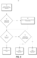
- method 500 can include tracking a local safe-stop trajectory. For example, if the vehicle control system 122 determines that the first fault is a critical fault because the first fault is associated with receiving data representing a motion plan from the autonomous driving system 110, then the vehicle control system 122 can retrieve a locally stored safe-stop trajectory previously received from the autonomous driving system 110 and track the local safe-stop trajectory.
- the vehicle control system 122 can track the local safe-stop trajectory based on the received data representing the dynamic state of the vehicle 10.
- the vehicle control system 122 can determine a dynamic state of the vehicle 10 based on an IMU and/or one or more redundant local sensors 109 associated with the vehicle control system 122, and the vehicle control system 122 can track the local safe-stop trajectory based on the determined dynamic state.
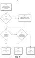
- the method 700 can include determining whether a redundancy threshold condition for the first operation is satisfied. For example, the vehicle control system 122 can access the fault reaction parameters data to determine a redundancy threshold value for the first operation, and determine if the n-th fault is a critical fault.
- the method 700 can include implementing a motion plan. For example, if the n-th fault causes the vehicle control system 122 to lose control of a stereo control system connected to a n-th control lane, and the vehicle control system 122 determines that a redundancy threshold value for stereo control is -1, then the vehicle control system 122 can implement the motion plan (to complete a vehicle service) without controlling the stereo.
- method 700 can include receiving a new motion plan associated with an assisted safe-stop action, and tracking an assisted safe-stop trajectory in the new motion plan.
- the vehicle control system 122 can retrieve a locally stored safe-stop trajectory previously received from the autonomous driving system 110 and track the local safe-stop trajectory.
- FIG. 8 depicts elements performed in a particular order for purposes of illustration and discussion. Those of ordinary skill in the art, using the disclosures provided herein, will understand that the elements FIG. 8 discussed herein can be adapted, rearranged, expanded, omitted, combined, and/or modified in various ways without deviating from the scope of the present invention.
- the method 800 can include determining a motion plan of an autonomous vehicle.
- the autonomous driving system 110 onboard the vehicle 10 can determine a motion plan for controlling a motion of the vehicle 10, based on sensor data 250 from sensor(s) 108.
- the motion plan can include one or more primary trajectories and a safe-stop trajectory associated with each primary trajectory.
- the autonomous driving system 110 can also determine a dynamic state of the autonomous vehicle.
- the method 800 can include providing the motion plan to a plurality of control lanes.
- the autonomous driving system 110 can provide data representing the motion plan to a plurality of control lanes of the vehicle control system 122.
- the autonomous driving system 110 can provide data representing the dynamic state of the autonomous vehicle to the plurality of control lanes of the vehicle control system 122.
- the plurality of control lanes can be configured to implement the motion plan to control the motion of the vehicle 10.
- the plurality of control lanes can include at least a first control lane and a second control lane.
- the vehicle control system 122 can control the first control lane to implement the motion plan (e.g., designate the first control lane as a primary lane, and designate the second control lane as a secondary lane).
- the vehicle control system 122 can control the first control lane to implement the motion plan by determining a primary trajectory based on the data representing the motion plan, controlling the first control lane to generate one or more first vehicle control signals to track the primary trajectory, and provide the one or more first vehicle control signals to one or more first vehicle actuation systems 124 connected to the first control lane.
- the vehicle control system 122 can control the first control lane and the second control lane to implement the motion plan.
- the vehicle control system 122 can control the first control lane to generate one or more first vehicle control signals to track the primary trajectory, and provide the one or more first vehicle control signals to one or more first vehicle actuation systems 124 connected to the first control lane; and control the second control lane to generate one or more second vehicle control signals to track the primary trajectory, and provide the one or more second vehicle control signals to one or more second vehicle actuation systems 124 connected to the second control lane.
- the method 800 can include detecting a first fault associated with implementation of the motion plan.
- the vehicle control system 122 can detect one or more faults associated with implementation of the motion plan by the first control lane or the second control lane.
- the vehicle control system 122 can detect one or more faults associated with implementation of the motion plan by one or more of the plurality of control lanes.
- the one or more faults can include, for example, at least one of a fault associated with receiving the data representing the motion plan, a fault associated with one or more of the plurality of control lanes, or a fault associated with one or more vehicle actuation systems 124 associated with the one or more of the plurality of control lanes.
- the vehicle control system 122 can determine a capability of the first control lane based on the one or more fault reaction parameters associated with the one or more faults, and control the first control lane to adjust the motion of the vehicle 10 based at least in part on the capability of the first control lane.
- the vehicle control system 122 can determine a capability of the first control lane and the second control lane based on the one or more fault reaction parameters associated with the one or more faults, and control the first control lane and the second control lane to adjust the motion of the vehicle 10 based at least in part on the capability of the first control lane and the second control lane.
- the vehicle control system 122 can determine a capability of the first control lane and the second control lane based on the one or more fault reaction parameters associated with the one or more faults, and control the second control lane to adjust the motion of the vehicle 10 based at least in part on the capability of the second control lane and the second control lane.
- the vehicle control system 122 can determine a capability of the plurality of control lanes in response to the one or more faults, determine the second control lane as a control lane with the highest capability from the plurality of control lanes, and control the second control lane to adjust the motion of the vehicle 10 based at least in part on one or more fault reaction parameters associated with the one or more faults.
- the method 800 can include determining a new motion plan.
- the vehicle control system 122 can provide one or more control signals to the autonomous driving system 110 that instruct the autonomous driving system 110 to determine a stopping action based on the one or more fault reaction parameters associated with the one or more faults.
- the vehicle control system 122 can receive data representing a motion plan from the autonomous driving system 110.
- the data representing the new motion plan can correspond to the stopping action, and the vehicle control system 122 can control the first control lane or the second control lane to implement the new motion plan corresponding to the stopping action.
- the method 800 can include tracking a local safe-stop trajectory.
- the vehicle control system 122 can retrieve a locally stored safe-stop trajectory that was previously received in the data representing the motion plan.
- the vehicle control system 122 can control the first control lane to generate one or more vehicle control signals to track the local safe-stop trajectory, and to provide the one or more vehicle control signals to one or more vehicle actuation systems 124 connected to the first control lane.
- the vehicle control system 122 can control the first control lane to determine a dynamic state of the vehicle 10.
- the dynamic state of the vehicle 10 can be determined by an inertial measurement unit (IMU) and/or additional sensors associated with the first control lane.
- the vehicle control system 122 can control the first control lane to adjust the local safe-stop trajectory based on the dynamic state of the vehicle 10.
- IMU inertial measurement unit
- the vehicle control system 122 can receive data representing a potential collision with one or more objects in an environment proximate to the vehicle 10.
- the vehicle control system 122 can receive the data from the collision mitigation system 126 onboard the vehicle 10.
- the vehicle control system 122 can control the first control lane to adjust the local safe-stop trajectory based on the data representing the potential collision (e.g., to avoid the potential collision).
- Computing tasks discussed herein as being performed at computing device(s) remote from the vehicle can instead be performed at the vehicle (e.g., via the vehicle computing system), or vice versa. Such configurations can be implemented without deviating from the scope of the present invention.
- the use of computer-based systems allows for a great variety of possible configurations, combinations, and divisions of tasks and functionality between and among components.
- Computer-implemented operations can be performed on a single component or across multiple components.
- Computer-implemented tasks and/or operations can be performed sequentially or in parallel.
- Data and instructions can be stored in a single memory device or across multiple memory devices.
Landscapes
- Engineering & Computer Science (AREA)
- Automation & Control Theory (AREA)
- Radar, Positioning & Navigation (AREA)
- Remote Sensing (AREA)
- Physics & Mathematics (AREA)
- General Physics & Mathematics (AREA)
- Theoretical Computer Science (AREA)
- Quality & Reliability (AREA)
- General Engineering & Computer Science (AREA)
- Transportation (AREA)
- Mechanical Engineering (AREA)
- Human Computer Interaction (AREA)
- Aviation & Aerospace Engineering (AREA)
- Control Of Driving Devices And Active Controlling Of Vehicle (AREA)
- Traffic Control Systems (AREA)
- Business, Economics & Management (AREA)
- Health & Medical Sciences (AREA)
- Artificial Intelligence (AREA)
- Evolutionary Computation (AREA)
- Game Theory and Decision Science (AREA)
- Medical Informatics (AREA)
Claims (15)
- Computerimplementiertes Verfahren, wobei das Verfahren umfasst:Empfangen von Bewegungsplanungsdaten für ein autonomes Fahrzeug (10);Bestimmen einer ersten Steuerspur (301; 401) einer Mehrzahl von Steuerspuren (301, 302; 401-403) zum Implementieren eines Bewegungsplans basierend auf den Bewegungsplanungsdaten,wobei die Mehrzahl von Steuerspuren mindestens die erste Steuerspur und eine zweite Steuerspur (302; 402), die sich von der ersten Steuerspur unterscheidet, umfassen, wobei die erste Steuerspur mit einem ersten Satz von Fahrzeugbetätigungssystemen (230; 311, 321, 331; 411, 421, 431, 451) entsprechend der ersten Steuerspur verbunden ist, wobei die zweite Steuerspur mit einem zweiten Satz von Fahrzeugbetätigungssystemen (240; 322, 332; 412, 422, 432, 452) entsprechend der zweiten Steuerspur verbunden ist,wobei der erste Satz von Fahrzeugbetätigungssystemen mindestens ein erstes Betätigungssystem umfasst, das im zweiten Satz von Fahrzeugbetätigungssystemen nicht vorhanden ist;wobei die erste Steuerspur dazu ausgelegt ist, eine erste Fähigkeit mindestens teilweise basierend auf dem ersten Satz von Fahrzeugbetätigungssystemen bereitzustellen, wobei die zweite Steuerspur dazu ausgelegt ist, eine zweite Fähigkeit zumindest teilweise basierend auf dem zweiten Satz von Fahrzeugbetätigungssystemen bereitzustellen, und wobei die erste Fähigkeit größer als die zweite Fähigkeit ist;Designieren der ersten Steuerspur als eine primäre Spur und der zweiten Steuerspur als eine sekundäre Spur basierend auf der ersten Fähigkeit und der zweiten Fähigkeit;Bestimmen eines Fehlers, der dem Implementieren des Bewegungsplans über die designierte primäre Spur zugeordnet ist;Ausschalten der designierten primären Spur undSteuern der designierten sekundären Spur, um eine Bewegung des autonomen Fahrzeugs zumindest teilweise basierend auf der Fähigkeit der designierten sekundären Spur anzupassen.
- Verfahren nach Anspruch 1, wobei das autonome Fahrzeug ein bodenbasiertes autonomes Fahrzeug ist.
- Verfahren nach Anspruch 2, wobei das bodenbasierte autonome Fahrzeug ein autonomer Lkw ist.
- Verfahren nach Anspruch 1, wobei die Bewegungsplanungsdaten eine Fahrzeugbahn angeben und wobei das Steuern der designierten sekundären Spur zum Anpassen der Bewegung des Fahrzeugs umfasst:
Steuern der designierten sekundären Spur zum:Erzeugen eines Fahrzeugsteuersignals oder mehrerer Fahrzeugsteuersignale, um die Fahrzeugbahn zu verfolgen; undBereitstellen des einen Fahrzeugsteuersignals oder der mehreren Fahrzeugsteuersignale an mindestens eines des zweiten Satzes von Fahrzeugbetätigungssystemen. - Verfahren nach einem der Ansprüche 1 bis 4, wobei das Bestimmen der ersten Steuerspur (301; 401) der Mehrzahl von Steuerspuren (301, 302; 401-403) zum Implementieren des Bewegungsplans basierend auf den Bewegungsplanungsdaten ein Steuern der designierten primären Spur zum Implementieren des Bewegungsplans umfasst.
- Verfahren nach Anspruch 1, wobei der erste Satz von Fahrzeugbetätigungssystemen umfasst:ein erstes Antriebsstrangsteuersystem (311; 411), das einen oder mehrere Antriebsaktuator(en) für einen Antrieb oder eine Beschleunigung des Fahrzeugs umfasst;ein erstes Lenksteuersystem (321; 421), das einen oder mehrere Lenkaktuator(en) für das Fahrzeug umfasst; undein erstes Bremssteuersystem (331; 431), das einen oder mehrere Bremsaktuator(en) für das Fahrzeug umfasst.
- Verfahren nach Anspruch 6, wobei der zweite Satz von Fahrzeugbetätigungssystemen umfasst:ein zweites Lenksteuersystem (322; 412), das einen oder mehrere Lenkaktuator(en) für das Fahrzeug umfasst; undein zweites Bremssteuersystem (332; 432), das einen oder mehrere Bremsaktuator(en) für das Fahrzeug umfasst.
- Verfahren nach Anspruch 7, wobei die ersten Lenkaktuatoren unabhängig von den zweiten Lenkaktuatoren funktionieren und wobei die ersten Bremsaktuatoren unabhängig von den zweiten Bremsaktuatoren funktionieren.
- Verfahren nach Anspruch 1, wobei der Fehler einem oder mehreren Fehlerreaktionsparameter(n) zugeordnet ist und wobei das Steuern der designierten sekundären Spur zum Anpassen der Bewegung des Fahrzeugs zumindest teilweise basierend auf der Fähigkeit der designierten sekundären Spur umfasst:
Steuern der designierten sekundären Spur zum Anpassen der Bewegung des Fahrzeugs zumindest teilweise basierend auf dem einen oder den mehreren Fehlerreaktionsparameter(n), der/die dem Fehler zugeordnet ist/sind, wobei der eine oder die mehreren Fehlerreaktionsparameter eine erste Verringerung der ersten Fähigkeit oder eine zweite Verringerung der zweiten Fähigkeit als Reaktion auf den Fehler angibt/angeben. - Verfahren nach Anspruch 9, wobei der eine oder die mehreren Fehlerreaktionsparameter eine Redundanzschwelle umfasst/umfassen, die einem Betrieb zugeordnet ist, der durch den Fehler beeinflusst wird.
- Verfahren nach Anspruch 1, wobei:der erste Satz von Fahrzeugbetätigungssystemen (311, 321, 331) dazu ausgelegt ist, eine Antriebssteuerung des Fahrzeugs bereitzustellen; undder zweite Satz von Fahrzeugbetätigungssystemen (322, 332) dazu ausgelegt ist, keine Antriebssteuerung des Fahrzeugs bereitzustellen.
- System zum Steuern eines autonomen Fahrzeugs (122), das umfasst:einen oder mehrere Prozessor(en) (112) undein oder mehrere materielle(s) nicht transitorische(s) computerlesbare(s) Medium/Medien (116), das/die Anweisungen (118) speichert/speichern, die, wenn sie durch den einen oder die mehreren Prozessor(en) ausgeführt werden, das System zum Steuern eines autonomen Fahrzeugs veranlassen, Vorgänge nach einem der Ansprüche 1 bis 11 durchzuführen.
- Autonomes Fahrzeug (10), das umfasst:eine Mehrzahl von Aktuatoren, die dazu ausgelegt sind, ein oder mehrere Fahrzeugsteuersignal(e) zu implementieren, um eine Bewegung des autonomen Fahrzeugs zu steuern; undein Fahrzeugsteuersystem nach Anspruch 12.
- Autonomes Fahrzeug nach Anspruch 13, das ferner umfasst:
ein autonomes Fahrsystem, das dazu ausgelegt ist, mindestens einen ersten Abschnitt der Bewegungsplanungsdaten für das autonome Fahrzeug zu erzeugen und den ersten Abschnitt der Bewegungsplanungsdaten an das Fahrzeugsteuersystem bereitzustellen. - Autonomes Fahrzeug nach Anspruch 14, wobei der erste Abschnitt der Bewegungsplanungsdaten eine oder mehrere primäre Bahn(en) und eine oder mehrere Anhaltebahn(en) angibt.
Applications Claiming Priority (4)
| Application Number | Priority Date | Filing Date | Title |
|---|---|---|---|
| US201762558523P | 2017-09-14 | 2017-09-14 | |
| US16/126,533 US11009874B2 (en) | 2017-09-14 | 2018-09-10 | Fault-tolerant control of an autonomous vehicle with multiple control lanes |
| PCT/US2018/050542 WO2019055442A1 (en) | 2017-09-14 | 2018-09-12 | TOLERANCE CONTROL OF FAILURE OF AN AUTONOMOUS VEHICLE WITH MULTIPLE CONTROL CHANNELS |
| EP18782848.8A EP3665061B1 (de) | 2017-09-14 | 2018-09-12 | Fehlertolerante steuerung eines autonomen fahrzeugs mit mehreren steuerungsspuren |
Related Parent Applications (1)
| Application Number | Title | Priority Date | Filing Date |
|---|---|---|---|
| EP18782848.8A Division EP3665061B1 (de) | 2017-09-14 | 2018-09-12 | Fehlertolerante steuerung eines autonomen fahrzeugs mit mehreren steuerungsspuren |
Publications (3)
| Publication Number | Publication Date |
|---|---|
| EP4235333A2 EP4235333A2 (de) | 2023-08-30 |
| EP4235333A3 EP4235333A3 (de) | 2024-01-17 |
| EP4235333B1 true EP4235333B1 (de) | 2025-07-09 |
Family
ID=65631033
Family Applications (2)
| Application Number | Title | Priority Date | Filing Date |
|---|---|---|---|
| EP23178010.7A Active EP4235333B1 (de) | 2017-09-14 | 2018-09-12 | Fehlertolerante steuerung eines autonomen fahrzeugs mit mehreren steuerungsspuren |
| EP18782848.8A Active EP3665061B1 (de) | 2017-09-14 | 2018-09-12 | Fehlertolerante steuerung eines autonomen fahrzeugs mit mehreren steuerungsspuren |
Family Applications After (1)
| Application Number | Title | Priority Date | Filing Date |
|---|---|---|---|
| EP18782848.8A Active EP3665061B1 (de) | 2017-09-14 | 2018-09-12 | Fehlertolerante steuerung eines autonomen fahrzeugs mit mehreren steuerungsspuren |
Country Status (4)
| Country | Link |
|---|---|
| US (5) | US11009874B2 (de) |
| EP (2) | EP4235333B1 (de) |
| JP (1) | JP7171708B2 (de) |
| WO (1) | WO2019055442A1 (de) |
Families Citing this family (40)
| Publication number | Priority date | Publication date | Assignee | Title |
|---|---|---|---|---|
| EP3400419B1 (de) * | 2016-01-05 | 2025-08-27 | Mobileye Vision Technologies Ltd. | Trainiertes navigationssystem mit auferlegten einschränkungen |
| US10571908B2 (en) | 2016-08-15 | 2020-02-25 | Ford Global Technologies, Llc | Autonomous vehicle failure mode management |
| US10611381B2 (en) * | 2017-10-24 | 2020-04-07 | Ford Global Technologies, Llc | Decentralized minimum risk condition vehicle control |
| DE102017010716A1 (de) * | 2017-11-10 | 2019-05-16 | Knorr-Bremse Systeme für Nutzfahrzeuge GmbH | System zum wenigstens teilautonomen Betrieb eines Kraftfahrzeugs mit doppelter Redundanz |
| US10726645B2 (en) | 2018-02-16 | 2020-07-28 | Ford Global Technologies, Llc | Vehicle diagnostic operation |
| US11148678B2 (en) * | 2019-04-26 | 2021-10-19 | GM Global Technology Operations LLC | Controlling operation of a vehicle with a supervisory control module having a fault-tolerant controller |
| US20200361452A1 (en) * | 2019-05-13 | 2020-11-19 | Toyota Research Institute, Inc. | Vehicles and methods for performing tasks based on confidence in accuracy of module output |
| JP7342495B2 (ja) * | 2019-07-30 | 2023-09-12 | マツダ株式会社 | 車両制御システム |
| EP3779514B1 (de) * | 2019-08-15 | 2023-05-03 | Apollo Intelligent Driving Technology (Beijing) Co., Ltd. | Autonomes fahrzeug und system für autonomes fahrzeug |
| CN112389461A (zh) * | 2019-08-15 | 2021-02-23 | 北京百度网讯科技有限公司 | 自动驾驶车辆以及用于自动驾驶车辆的系统 |
| US11676429B2 (en) * | 2019-09-04 | 2023-06-13 | Ford Global Technologies, Llc | Vehicle wheel impact detection and response |
| US20210097786A1 (en) * | 2019-09-19 | 2021-04-01 | Steering Solutions Ip Holding Corporation | Method and product for monitoring and responding to component changes in an autonomous driving system |
| JP7207256B2 (ja) * | 2019-10-15 | 2023-01-18 | トヨタ自動車株式会社 | 車両制御システム |
| CN111025959B (zh) * | 2019-11-20 | 2021-10-01 | 华为技术有限公司 | 一种数据管理的方法、装置、设备及智能汽车 |
| CN110682920B (zh) * | 2019-12-09 | 2020-04-21 | 吉利汽车研究院(宁波)有限公司 | 一种自动驾驶控制系统、控制方法及设备 |
| JP6937855B2 (ja) * | 2020-01-29 | 2021-09-22 | 本田技研工業株式会社 | 車両制御装置、車両、車両制御方法及びプログラム |
| EP4096980A1 (de) * | 2020-01-31 | 2022-12-07 | ZF CV Systems Global GmbH | Asymmetrische ausfallsichere systemarchitektur |
| EP3862791B1 (de) | 2020-02-07 | 2025-03-26 | Harman Becker Automotive Systems GmbH | Telematiksteuerungseinheit, die positionierungsdaten mit integritätsniveau bereitstellt |
| US11513517B2 (en) * | 2020-03-30 | 2022-11-29 | Uatc, Llc | System and methods for controlling state transitions using a vehicle controller |
| JP7427809B2 (ja) * | 2020-05-20 | 2024-02-05 | 華為技術有限公司 | 冗長電子制御システムおよびデバイス |
| US11634160B2 (en) * | 2020-08-14 | 2023-04-25 | Waymo Llc | Thermal management of steering system for autonomous vehicles |
| JP7405067B2 (ja) * | 2020-12-11 | 2023-12-26 | トヨタ自動車株式会社 | 車両の制御装置、及び車両の制御方法 |
| US20220185325A1 (en) * | 2020-12-13 | 2022-06-16 | Pony Ai Inc. | Vehicle safety response control hierarchies and corresponding methods of automated vehicle safety control |
| US11667302B2 (en) | 2020-12-13 | 2023-06-06 | Pony Ai Inc. | Automated vehicle safety response methods and corresponding vehicle safety systems with serialized computing architectures |
| US11827243B2 (en) | 2020-12-13 | 2023-11-28 | Pony Ai Inc. | Automated vehicle safety response methods and corresponding vehicle safety systems with serial-parallel computing architectures |
| CN116745180A (zh) | 2021-01-12 | 2023-09-12 | 苹果公司 | 使用停止轨迹的自动化控制 |
| US11214271B1 (en) * | 2021-03-10 | 2022-01-04 | Aurora Operations, Inc. | Control system interface for autonomous vehicle |
| US12497028B1 (en) * | 2021-05-23 | 2025-12-16 | Zoox, Inc. | Autonomous vehicle fault injection testing |
| DE102021207578A1 (de) * | 2021-07-16 | 2023-01-19 | Volkswagen Aktiengesellschaft | Vorrichtung und Verfahren zur Erzeugung und Übertragung von Steuerbefehlen für ein automatisiert fahrendes Kraftfahrzeug |
| CN113586263B (zh) * | 2021-07-27 | 2023-08-29 | 珠海云洲智能科技股份有限公司 | 一种断油保护方法、主控装置及智控装置 |
| US11807275B2 (en) * | 2021-08-09 | 2023-11-07 | GM Global Technology Operations LLC | Method and process for degradation mitigation in automated driving |
| CN113671961B (zh) * | 2021-08-20 | 2023-03-28 | 清华大学 | 多车协同制动有限时间容错控制方法、系统、介质及设备 |
| CN113696902A (zh) * | 2021-08-31 | 2021-11-26 | 蔚来汽车科技(安徽)有限公司 | 车辆控制系统、方法、计算机设备、介质及车辆 |
| USD1113973S1 (en) | 2021-09-30 | 2026-02-17 | Zoox, Inc. | Display screen or portion thereof having an animated graphical user interface |
| US12415525B1 (en) * | 2021-09-30 | 2025-09-16 | Zoox, Inc. | Fault diagnosis for autonomous vehicles |
| US12311854B2 (en) * | 2021-10-07 | 2025-05-27 | Sygnal Technologies, Inc. | Fail-safe signal injection |
| JP7768166B2 (ja) * | 2023-02-28 | 2025-11-12 | トヨタ自動車株式会社 | 車両 |
| US12162464B2 (en) * | 2023-03-22 | 2024-12-10 | Plusai, Inc. | Redundant brake and brake failover for autonomous vehicles |
| EP4523990A1 (de) | 2023-09-18 | 2025-03-19 | aiMotive Kft. | Redundante architektur für automatisiertes oder autonomes fahren |
| US20250189993A1 (en) * | 2023-12-11 | 2025-06-12 | Industrial Technology Research Institute | Control system and control method for flight vehicle |
Family Cites Families (15)
| Publication number | Priority date | Publication date | Assignee | Title |
|---|---|---|---|---|
| JP2012128697A (ja) | 2010-12-16 | 2012-07-05 | Hitachi Ltd | 情報処理装置 |
| DE102011117116B4 (de) | 2011-10-27 | 2014-02-13 | Diehl Bgt Defence Gmbh & Co. Kg | Steuereinrichtung zum wenigstens teilweise autonomen Betrieb eines Fahrzeugs und Fahrzeug mit solch einer Steuereinrichtung |
| DE102013213171A1 (de) | 2013-07-04 | 2015-01-08 | Robert Bosch Gmbh | Verfahren und Vorrichtung zum Betreiben eines Kraftfahrzeugs in einem automatisierten Fahrbetrieb |
| DE102013213169A1 (de) | 2013-07-04 | 2015-01-08 | Robert Bosch Gmbh | Verfahren und Vorrichtung zum Betreiben eines Kraftfahrzeugs in einem automatisierten Fahrbetrieb |
| DE102013020177A1 (de) | 2013-11-30 | 2014-06-18 | Daimler Ag | Kraftfahrzeug |
| US9195232B1 (en) | 2014-02-05 | 2015-11-24 | Google Inc. | Methods and systems for compensating for common failures in fail operational systems |
| US9604585B2 (en) * | 2014-07-11 | 2017-03-28 | Ford Global Technologies, Llc | Failure management in a vehicle |
| JP6394497B2 (ja) * | 2015-05-25 | 2018-09-26 | トヨタ自動車株式会社 | 車両の自動運転システム |
| EP3305620B1 (de) * | 2015-06-03 | 2019-08-07 | Nissan Motor Co., Ltd. | Fahrzeugsteuerungsvorrichtung und fahrzeugsteuerungsverfahren |
| EP3118703B1 (de) | 2015-07-13 | 2018-05-23 | Volvo Car Corporation | Sicherheitstoppvorrichtung und verfahren für einen sicherheitstopp eines autonomen fahrzeuges |
| US9566986B1 (en) * | 2015-09-25 | 2017-02-14 | International Business Machines Corporation | Controlling driving modes of self-driving vehicles |
| DE102015222605A1 (de) | 2015-11-17 | 2017-05-18 | MAN Trucks & Bus AG | Verfahren und Vorrichtung zum assistierten, teilautomatisierten, hochautomatisierten, vollautomatisierten oder fahrerlosen Fahren eines Kraftfahrzeuges |
| JP6424848B2 (ja) * | 2016-02-17 | 2018-11-21 | トヨタ自動車株式会社 | 自動運転車両の制御装置 |
| US10730531B1 (en) * | 2017-02-02 | 2020-08-04 | Uatc, Llc | Machine-learning based vehicle motion control system |
| US10809719B2 (en) * | 2017-08-29 | 2020-10-20 | Uatc, Llc | Systems and methods of controlling an autonomous vehicle using an enhanced trajectory following configuration |
-
2018
- 2018-09-10 US US16/126,533 patent/US11009874B2/en active Active
- 2018-09-12 WO PCT/US2018/050542 patent/WO2019055442A1/en not_active Ceased
- 2018-09-12 EP EP23178010.7A patent/EP4235333B1/de active Active
- 2018-09-12 JP JP2020515232A patent/JP7171708B2/ja active Active
- 2018-09-12 EP EP18782848.8A patent/EP3665061B1/de active Active
-
2021
- 2021-05-17 US US17/322,231 patent/US11307579B2/en active Active
-
2022
- 2022-03-15 US US17/695,055 patent/US12055933B2/en active Active
-
2023
- 2023-10-05 US US18/481,683 patent/US12038747B2/en active Active
-
2024
- 2024-06-24 US US18/752,228 patent/US20240393784A1/en active Pending
Also Published As
| Publication number | Publication date |
|---|---|
| US20240393784A1 (en) | 2024-11-28 |
| US11009874B2 (en) | 2021-05-18 |
| JP2020534203A (ja) | 2020-11-26 |
| US20190079513A1 (en) | 2019-03-14 |
| EP3665061A1 (de) | 2020-06-17 |
| US12055933B2 (en) | 2024-08-06 |
| EP4235333A2 (de) | 2023-08-30 |
| US20210271240A1 (en) | 2021-09-02 |
| WO2019055442A1 (en) | 2019-03-21 |
| US20240028033A1 (en) | 2024-01-25 |
| US12038747B2 (en) | 2024-07-16 |
| US20220206490A1 (en) | 2022-06-30 |
| US11307579B2 (en) | 2022-04-19 |
| EP3665061B1 (de) | 2023-06-14 |
| JP7171708B2 (ja) | 2022-11-15 |
| EP4235333A3 (de) | 2024-01-17 |
Similar Documents
| Publication | Publication Date | Title |
|---|---|---|
| US12038747B2 (en) | Fault-tolerant control of an autonomous vehicle with multiple control lanes | |
| US11644831B2 (en) | Multi-stage operation of autonomous vehicles | |
| US11724708B2 (en) | Fail-safe handling system for autonomous driving vehicle | |
| US12565224B2 (en) | Vehicular control system having a plurality of electronic control units | |
| US10875511B2 (en) | Systems and methods for brake redundancy for an autonomous vehicle | |
| CN102227612B (zh) | 自主驾驶车辆的控制和系统 | |
| WO2020132001A1 (en) | Multi-controller synchronization | |
| US20200391729A1 (en) | Method to monitor control system of autonomous driving vehicle with multiple levels of warning and fail operations | |
| US20230311929A1 (en) | Autonomous vehicle interaction with chassis control system to provide enhanced driving modes | |
| EP4022258B1 (de) | Monitorzuweisungssystem und -verfahren | |
| CN113533876A (zh) | 用于执行自主驾驶车辆的电磁兼容性测试的方法和系统 | |
| US20190359222A1 (en) | Contingency plan system and method | |
| US20240166245A1 (en) | Mutual monitoring of high-performance computing (hpc) systems to control vehicle operation |
Legal Events
| Date | Code | Title | Description |
|---|---|---|---|
| PUAI | Public reference made under article 153(3) epc to a published international application that has entered the european phase |
Free format text: ORIGINAL CODE: 0009012 |
|
| STAA | Information on the status of an ep patent application or granted ep patent |
Free format text: STATUS: REQUEST FOR EXAMINATION WAS MADE |
|
| 17P | Request for examination filed |
Effective date: 20230607 |
|
| AC | Divisional application: reference to earlier application |
Ref document number: 3665061 Country of ref document: EP Kind code of ref document: P |
|
| AK | Designated contracting states |
Kind code of ref document: A2 Designated state(s): AL AT BE BG CH CY CZ DE DK EE ES FI FR GB GR HR HU IE IS IT LI LT LU LV MC MK MT NL NO PL PT RO RS SE SI SK SM TR |
|
| REG | Reference to a national code |
Ref country code: DE Ref legal event code: R079 Free format text: PREVIOUS MAIN CLASS: G05D0001000000 Ipc: B60W0060000000 Ref document number: 602018083557 Country of ref document: DE |
|
| PUAL | Search report despatched |
Free format text: ORIGINAL CODE: 0009013 |
|
| AK | Designated contracting states |
Kind code of ref document: A3 Designated state(s): AL AT BE BG CH CY CZ DE DK EE ES FI FR GB GR HR HU IE IS IT LI LT LU LV MC MK MT NL NO PL PT RO RS SE SI SK SM TR |
|
| RIC1 | Information provided on ipc code assigned before grant |
Ipc: B60W 50/029 20120101ALN20231212BHEP Ipc: G01C 21/16 20060101ALI20231212BHEP Ipc: G06F 11/20 20060101ALI20231212BHEP Ipc: G05D 1/00 20060101ALI20231212BHEP Ipc: B60W 50/023 20120101ALI20231212BHEP Ipc: B60W 60/00 20200101AFI20231212BHEP |
|
| STAA | Information on the status of an ep patent application or granted ep patent |
Free format text: STATUS: EXAMINATION IS IN PROGRESS |
|
| 17Q | First examination report despatched |
Effective date: 20240119 |
|
| RAP3 | Party data changed (applicant data changed or rights of an application transferred) |
Owner name: UATC, LLC |
|
| RAP1 | Party data changed (applicant data changed or rights of an application transferred) |
Owner name: AURORA OPERATIONS, INC. |
|
| GRAP | Despatch of communication of intention to grant a patent |
Free format text: ORIGINAL CODE: EPIDOSNIGR1 |
|
| STAA | Information on the status of an ep patent application or granted ep patent |
Free format text: STATUS: GRANT OF PATENT IS INTENDED |
|
| RIC1 | Information provided on ipc code assigned before grant |
Ipc: B60W 50/029 20120101ALN20250117BHEP Ipc: G01C 21/16 20060101ALI20250117BHEP Ipc: G06F 11/20 20060101ALI20250117BHEP Ipc: G05D 1/00 20060101ALI20250117BHEP Ipc: B60W 50/023 20120101ALI20250117BHEP Ipc: B60W 60/00 20200101AFI20250117BHEP |
|
| INTG | Intention to grant announced |
Effective date: 20250130 |
|
| GRAS | Grant fee paid |
Free format text: ORIGINAL CODE: EPIDOSNIGR3 |
|
| GRAA | (expected) grant |
Free format text: ORIGINAL CODE: 0009210 |
|
| STAA | Information on the status of an ep patent application or granted ep patent |
Free format text: STATUS: THE PATENT HAS BEEN GRANTED |
|
| AC | Divisional application: reference to earlier application |
Ref document number: 3665061 Country of ref document: EP Kind code of ref document: P |
|
| AK | Designated contracting states |
Kind code of ref document: B1 Designated state(s): AL AT BE BG CH CY CZ DE DK EE ES FI FR GB GR HR HU IE IS IT LI LT LU LV MC MK MT NL NO PL PT RO RS SE SI SK SM TR |
|
| REG | Reference to a national code |
Ref country code: GB Ref legal event code: FG4D |
|
| REG | Reference to a national code |
Ref country code: CH Ref legal event code: EP |
|
| REG | Reference to a national code |
Ref country code: IE Ref legal event code: FG4D |
|
| REG | Reference to a national code |
Ref country code: DE Ref legal event code: R096 Ref document number: 602018083557 Country of ref document: DE |
|
| PGFP | Annual fee paid to national office [announced via postgrant information from national office to epo] |
Ref country code: DE Payment date: 20250926 Year of fee payment: 8 |
|
| REG | Reference to a national code |
Ref country code: NL Ref legal event code: MP Effective date: 20250709 |
|
| PG25 | Lapsed in a contracting state [announced via postgrant information from national office to epo] |
Ref country code: PT Free format text: LAPSE BECAUSE OF FAILURE TO SUBMIT A TRANSLATION OF THE DESCRIPTION OR TO PAY THE FEE WITHIN THE PRESCRIBED TIME-LIMIT Effective date: 20251110 |
|
| PG25 | Lapsed in a contracting state [announced via postgrant information from national office to epo] |
Ref country code: NL Free format text: LAPSE BECAUSE OF FAILURE TO SUBMIT A TRANSLATION OF THE DESCRIPTION OR TO PAY THE FEE WITHIN THE PRESCRIBED TIME-LIMIT Effective date: 20250709 |
|
| REG | Reference to a national code |
Ref country code: AT Ref legal event code: MK05 Ref document number: 1811618 Country of ref document: AT Kind code of ref document: T Effective date: 20250709 |
|
| PG25 | Lapsed in a contracting state [announced via postgrant information from national office to epo] |
Ref country code: IS Free format text: LAPSE BECAUSE OF FAILURE TO SUBMIT A TRANSLATION OF THE DESCRIPTION OR TO PAY THE FEE WITHIN THE PRESCRIBED TIME-LIMIT Effective date: 20251109 |
|
| PG25 | Lapsed in a contracting state [announced via postgrant information from national office to epo] |
Ref country code: NO Free format text: LAPSE BECAUSE OF FAILURE TO SUBMIT A TRANSLATION OF THE DESCRIPTION OR TO PAY THE FEE WITHIN THE PRESCRIBED TIME-LIMIT Effective date: 20251009 |
|
| REG | Reference to a national code |
Ref country code: LT Ref legal event code: MG9D |
|
| PG25 | Lapsed in a contracting state [announced via postgrant information from national office to epo] |
Ref country code: AT Free format text: LAPSE BECAUSE OF FAILURE TO SUBMIT A TRANSLATION OF THE DESCRIPTION OR TO PAY THE FEE WITHIN THE PRESCRIBED TIME-LIMIT Effective date: 20250709 |
|
| PG25 | Lapsed in a contracting state [announced via postgrant information from national office to epo] |
Ref country code: FI Free format text: LAPSE BECAUSE OF FAILURE TO SUBMIT A TRANSLATION OF THE DESCRIPTION OR TO PAY THE FEE WITHIN THE PRESCRIBED TIME-LIMIT Effective date: 20250709 |
|
| PG25 | Lapsed in a contracting state [announced via postgrant information from national office to epo] |
Ref country code: HR Free format text: LAPSE BECAUSE OF FAILURE TO SUBMIT A TRANSLATION OF THE DESCRIPTION OR TO PAY THE FEE WITHIN THE PRESCRIBED TIME-LIMIT Effective date: 20250709 |
|
| PG25 | Lapsed in a contracting state [announced via postgrant information from national office to epo] |
Ref country code: GR Free format text: LAPSE BECAUSE OF FAILURE TO SUBMIT A TRANSLATION OF THE DESCRIPTION OR TO PAY THE FEE WITHIN THE PRESCRIBED TIME-LIMIT Effective date: 20251010 |
|
| PG25 | Lapsed in a contracting state [announced via postgrant information from national office to epo] |
Ref country code: SE Free format text: LAPSE BECAUSE OF FAILURE TO SUBMIT A TRANSLATION OF THE DESCRIPTION OR TO PAY THE FEE WITHIN THE PRESCRIBED TIME-LIMIT Effective date: 20250709 |
|
| PG25 | Lapsed in a contracting state [announced via postgrant information from national office to epo] |
Ref country code: LV Free format text: LAPSE BECAUSE OF FAILURE TO SUBMIT A TRANSLATION OF THE DESCRIPTION OR TO PAY THE FEE WITHIN THE PRESCRIBED TIME-LIMIT Effective date: 20250709 |
|
| PG25 | Lapsed in a contracting state [announced via postgrant information from national office to epo] |
Ref country code: PL Free format text: LAPSE BECAUSE OF FAILURE TO SUBMIT A TRANSLATION OF THE DESCRIPTION OR TO PAY THE FEE WITHIN THE PRESCRIBED TIME-LIMIT Effective date: 20250709 Ref country code: BG Free format text: LAPSE BECAUSE OF FAILURE TO SUBMIT A TRANSLATION OF THE DESCRIPTION OR TO PAY THE FEE WITHIN THE PRESCRIBED TIME-LIMIT Effective date: 20250709 |
|
| PG25 | Lapsed in a contracting state [announced via postgrant information from national office to epo] |
Ref country code: RS Free format text: LAPSE BECAUSE OF FAILURE TO SUBMIT A TRANSLATION OF THE DESCRIPTION OR TO PAY THE FEE WITHIN THE PRESCRIBED TIME-LIMIT Effective date: 20251009 |
|
| PG25 | Lapsed in a contracting state [announced via postgrant information from national office to epo] |
Ref country code: ES Free format text: LAPSE BECAUSE OF FAILURE TO SUBMIT A TRANSLATION OF THE DESCRIPTION OR TO PAY THE FEE WITHIN THE PRESCRIBED TIME-LIMIT Effective date: 20250709 |
|
| PG25 | Lapsed in a contracting state [announced via postgrant information from national office to epo] |
Ref country code: RO Free format text: LAPSE BECAUSE OF FAILURE TO SUBMIT A TRANSLATION OF THE DESCRIPTION OR TO PAY THE FEE WITHIN THE PRESCRIBED TIME-LIMIT Effective date: 20250709 |