EP4474833A1 - Elektrischer stromsensor - Google Patents
Elektrischer stromsensor Download PDFInfo
- Publication number
- EP4474833A1 EP4474833A1 EP22924986.7A EP22924986A EP4474833A1 EP 4474833 A1 EP4474833 A1 EP 4474833A1 EP 22924986 A EP22924986 A EP 22924986A EP 4474833 A1 EP4474833 A1 EP 4474833A1
- Authority
- EP
- European Patent Office
- Prior art keywords
- current
- small
- units
- current unit
- plane
- Prior art date
- Legal status (The legal status is an assumption and is not a legal conclusion. Google has not performed a legal analysis and makes no representation as to the accuracy of the status listed.)
- Pending
Links
Images


Classifications
-
- G—PHYSICS
- G01—MEASURING; TESTING
- G01R—MEASURING ELECTRIC VARIABLES; MEASURING MAGNETIC VARIABLES
- G01R19/00—Arrangements for measuring currents or voltages or for indicating presence or sign thereof
- G01R19/0092—Measuring current only
-
- G—PHYSICS
- G01—MEASURING; TESTING
- G01R—MEASURING ELECTRIC VARIABLES; MEASURING MAGNETIC VARIABLES
- G01R1/00—Details of instruments or arrangements of the types included in groups G01R5/00 - G01R13/00 and G01R31/00
- G01R1/02—General constructional details
- G01R1/06—Measuring leads; Measuring probes
- G01R1/067—Measuring probes
- G01R1/07—Non contact-making probes
-
- G—PHYSICS
- G01—MEASURING; TESTING
- G01R—MEASURING ELECTRIC VARIABLES; MEASURING MAGNETIC VARIABLES
- G01R1/00—Details of instruments or arrangements of the types included in groups G01R5/00 - G01R13/00 and G01R31/00
- G01R1/02—General constructional details
- G01R1/18—Screening arrangements against electric or magnetic fields, e.g. against earth's field
-
- G—PHYSICS
- G01—MEASURING; TESTING
- G01R—MEASURING ELECTRIC VARIABLES; MEASURING MAGNETIC VARIABLES
- G01R15/00—Details of measuring arrangements of the types provided for in groups G01R17/00 - G01R29/00, G01R33/00 - G01R33/26 or G01R35/00
- G01R15/14—Adaptations providing voltage or current isolation, e.g. for high-voltage or high-current networks
- G01R15/20—Adaptations providing voltage or current isolation, e.g. for high-voltage or high-current networks using galvano-magnetic devices, e.g. Hall-effect devices, i.e. measuring a magnetic field via the interaction between a current and a magnetic field, e.g. magneto resistive or Hall effect devices
- G01R15/205—Adaptations providing voltage or current isolation, e.g. for high-voltage or high-current networks using galvano-magnetic devices, e.g. Hall-effect devices, i.e. measuring a magnetic field via the interaction between a current and a magnetic field, e.g. magneto resistive or Hall effect devices using magneto-resistance devices, e.g. field plates
-
- G—PHYSICS
- G01—MEASURING; TESTING
- G01R—MEASURING ELECTRIC VARIABLES; MEASURING MAGNETIC VARIABLES
- G01R15/00—Details of measuring arrangements of the types provided for in groups G01R17/00 - G01R29/00, G01R33/00 - G01R33/26 or G01R35/00
- G01R15/14—Adaptations providing voltage or current isolation, e.g. for high-voltage or high-current networks
- G01R15/20—Adaptations providing voltage or current isolation, e.g. for high-voltage or high-current networks using galvano-magnetic devices, e.g. Hall-effect devices, i.e. measuring a magnetic field via the interaction between a current and a magnetic field, e.g. magneto resistive or Hall effect devices
- G01R15/207—Constructional details independent of the type of device used
Definitions
- the present invention relates to a current sensor that measures a measurement-target current flowing through a bus bar based on magnetism.
- a plurality of detection units are required to be integrated.
- problems may occur such as being out of a measurement range of a magnetic sensor in the detection unit where a large magnitude of current is applied, or errors may occur due to magnetic saturation of shields of the detection units and other influence of the detection units.
- PTL 1 for the purpose of providing a current sensor capable of obtaining a wide dynamic range of input current, it is described that a plurality of magnetoresistive elements are disposed at positions having different distances from a current center in a current sensor for detecting magnetism generated by current.
- a magnetoresistive element for a large current and a magnetoresistive element for a small current are disposed and a position relative to a conductor is designed to constitute a current detector of the current sensor having a wide dynamic range.
- An object of the present invention is to provide a current sensor in which a large-current unit through which a large current flows and a small-current unit through which a small current flows are integrated, a wide measurement range for the large-current unit is attained, and measurement errors due to magnetic saturation of shields or other influence of the detection units are suppressed.
- the present invention provides the following configuration as means for solving the above-mentioned problem.
- a current sensor has a plurality of units which are integrally formed and each of which has a bus bar of a flat plate shape which allows current to flow and which extends in a first direction, a magnetic sensor disposed so as to face one of plate surfaces of the bus bar, and a shield having a base of a flat plate shape which is disposed so as to face the other plate surface of the bus bar.
- Each of the plurality of units includes a large-current unit in which relatively large current flows in the bus bar and a small-current unit in which relatively small current flows in the bus bar.
- a direction normal to the plate surfaces of the bus bar is determined as a second direction and a direction orthogonal to the first direction and the second direction is determined as a third direction
- a first distance between the bus bar and the magnetic sensor in the second direction is the same for the large-current unit and the small-current unit
- a second distance between the bus bar and the base in the second direction of the large-current unit is larger than that of the small-current unit.
- a measurement error of the current sensor may be suppressed by suppressing magnetic saturation of the shield by the magnetism from the bus bar.
- the large-current unit and the small-current unit may have the same bus bar, the same magnetic sensor and the same shield.
- the shield may have, at opposite ends of the base in the third direction, standing portions extending to a side where the bus bar and the magnetic sensor are arranged in the second direction.
- end portions of the shield may be located between the magnetic sensor and the bus bar in the second direction.
- the measurable current range of the large-current unit and the small-current unit may be adjusted by adjusting an effect of enhancing the magnetism generated by the current flowing through the bus bar with the shield.
- the current sensor may include a large-current unit group having the plurality of large-current units arranged at an interval a1 in the third direction, and a small-current unit group having the plurality of small-current units arranged at an interval a2 in the third direction.
- One of the large-current units and one of the small-current units may be arranged adjacent to each other with an interval b.
- the bus bars of the large-current units may be arranged on a plane A.
- the bus bars of the small-current units may be arranged on a plane B.
- the plane A and the plane B may be the same plane.
- the interval b may be larger than the interval a1.
- the interval b may be larger than the interval a2.
- the current sensor may include a large-current unit group having the plurality of large-current units arranged at an interval a1 in the third direction, and a small-current unit group having the plurality of small-current units arranged at an interval a2 in the third direction.
- One of the large-current units and one of the small-current units may be arranged adjacent to each other with an interval b.
- the bus bars of the large-current units may be arranged on a plane A.
- the bus bars of the small-current units may be arranged on a plane B.
- the plane A and the plane B may be different from each other.
- the interval b may be equal to or larger than the interval a1.
- the interval b may be equal to or larger than the interval a2.
- a size of the current sensor in the second direction may be reduced, and when the plane A and the plane B are different planes, a size of the current sensor in the third direction may be reduced.
- the plurality of units may be arranged in the third direction.
- the adjacent units When magnitudes of currents flowing through the bus bars of the adjacent units are different from each other, the adjacent units may be arranged on the same straight line extending in the third direction.
- the adjacent units When magnitudes of currents flowing through the bus bars of the adjacent units are the same as each other, the adjacent units may be arranged on the same straight line extending in the third direction.
- the current sensor may include a large-current unit group having the plurality of large-current units and a small-current unit group having the plurality of small-current units.
- the bus bars of the large-current units may be arranged on a plane A.
- the bus bars of the small-current units may be arranged on a plane B.
- the plane A and the plane B may be the same plane.
- the adjacent large-current units may not be arranged on the same straight line extending in the third direction.
- the adjacent small-current units may not be arranged on the same straight line extending in the third direction.
- One of the large-current units and one of the small-current units may be arranged adjacent to each other on the same straight line extending in the third direction.
- the current sensor may include a small-current unit group having the plurality of small-current units and the large-current unit.
- the bus bar of the large-current unit may be arranged on a plane A.
- the bus bars of the small-current units may be arranged on a plane B.
- the plane A and the plane B may be the same plane.
- the adjacent small-current units may not be arranged on the same straight line extending in the third direction.
- the large-current unit and one of the small-current units may be arranged adjacent to each other on the same straight line extending in the third direction.
- the distance between the units in the third direction may be reduced and the current sensor may be miniaturized.
- the current sensor may further include a medium-current unit in which current of a magnitude between a current value of current flowing through the large-current units and a current value of current flowing through the small-current units flows.
- a current sensor including a large-current unit and a small-current unit which are integrated, with a wide measurable current range and a small measurement error, may be provided.
- FIGS. 1A and 1B are a plan view and a cross-sectional view, respectively, schematically illustrating an important portion of a current sensor 10 according to this embodiment.
- the current sensor 10 includes a plurality of units 11, and the plurality of units 11 are integrated.
- Each of the plurality of units 11 has a bus bar 12, a magnetic sensor 13, and a shield 14.
- a direction in which the bus bar 12 extends is determined as an X-axis direction
- a direction normal to plate surfaces 12a and 12b of the bus bar 12 is determined as a Y-axis direction
- a direction orthogonal to the first direction and the second direction is determined as a Z-axis direction.
- the bus bar 12 has a flat plate shape, extends in the first direction (in the X-axis direction), allows current to be detected to flow, and is composed of copper, brass, aluminum, or the like. Note that the bus bar 12 may not have the flat plate shape and may be bent at a portion other than portions facing the magnetic sensor 13 and the shield 14.
- the magnetic sensor 13 is positioned so as to face the plate surface 12a which is one (on a side in a Y-axis direction Y1) of the plate surfaces of the bus bar 12, and is mounted on a substrate, not illustrated, to detect magnetism caused by a measurement target current flowing through the bus bar 12.
- a magnetoresistive effect element such as a GMR element or a TMR element, using a magnetoresistive effect in which an electrical resistance changes depending on an external magnetic field is used.
- the shield 14 has a flat base 14a disposed so as to face the plate surface 12b of the other side of the bus bar 12 (Y-axis direction Y2 side).
- the shield 14 has standing portions 14b extending from opposite ends 14c of a base 14a in the third direction (Z-axis direction) to one side in the second direction (Y-axis direction).
- the one side in the second direction is a side where the bus bar 12 and the magnetic sensor 13 are arranged in relation to the base 14a when the shield 14 is incorporated as the unit 11.
- the shield 14 suppresses electromagnetic interference caused by the bus bar 12.
- the shield 14 is configured by stacking a plurality of metal plates of the same shape.
- the plurality of units 11 include a large-current unit 11A in which relatively large current flows in the bus bar 12 and a small-current unit 11B in which relatively small current flows in the bus bar 12.
- a large-current unit 11A in which relatively large current flows in the bus bar 12
- a small-current unit 11B in which relatively small current flows in the bus bar 12.
- the same bus bar 12 means that portions where the magnetic sensor 13 and the shield 14 overlap with the bus bar 12 are the same in the second direction (Y-axis direction). Therefore, the bus bars 12 may have different lengths and different end shapes in the first direction (X-axis direction).
- a distance L1A in the large-current unit 11A is the same as a distance L1B in the small-current unit 11B.
- a distance L2A in the large-current unit 11A is larger than a distance L2B in the small-current unit 11B.
- a distance L3A in the large-current unit 11A is larger than a distance L3B in the small-current unit 11B.
- the distance L3A is 0 in FIG. 1A .
- the distances L1, L2, and L3 between the corresponding members are distances between centers of the corresponding members in the second direction.
- the shield 14 also functions as a yoke for magnetism (induced magnetic field) generated by the current flowing through the bus bar 12, and the magnetism emitted from the end portion 14e of the shield 14 is measured by the magnetic sensor 13. Therefore, a magnitude of the magnetism caused by the current of the bus bar 12 measured by the magnetic sensor 13 may be adjusted by the distances L2 and L3. In other words, when the distances L2 and L3 are increased, an effect of the shield 14 to strengthen the magnetism caused by the current of the bus bar 12 may be suppressed and the magnetism reaching the magnetic sensor 13 may be reduced.
- the shield 14 for the large-current unit 11A and the shield 14 for the small-current unit 11B are configured by the same components.
- the effect of enhancing the magnetism generated by the current of the bus bar 12 may be differentiated using the same shield 14. Since the distance L3 increases when the distance L2 is increased, the effect of increasing the magnetism of the shield 14 in the large-current unit 11A may be suppressed. By increasing the distances L2 and L3, the magnetism reaching the magnetic sensor 13 may be reduced when a large current is applied to the bus bar 12. Therefore, a range of current flowing through the bus bar 12 measurable by the large-current unit 11A may be increased.
- the current sensor 10 having a small current detection error by maintaining a function of suppressing magnetism of the shield 14 may be attained.
- the end portion 14e of the shield 14 (standing portion 14b) is located between the magnetic sensor 13 and the bus bar 12 in the second direction, the magnetism generated by the current flowing through the bus bar 12 may be enhanced by the shield 14.
- the end portions 14e are located between a center point of the magnetic sensor 13 and a center point of the bus bar 12 in the second direction. Therefore, as illustrated in FIG. 1B , a case where the center point of the magnetic sensor 13 and the end portions 14e are located in the same position in the second direction is also included.
- the end portions 14e of the shield 14 are not the ends 14c of the opposite sides of the shield 14 in the Z-axis direction, but tip ends of the standing portions 14b on the Y1 side in the Y-axis direction.
- the distance L3A of the large-current unit 11A is larger than the distance L3B of the small-current unit 11B.
- the effect of enhancing the magnetism generated by the current flowing through the bus bar 12 is differentiated between the large-current unit 11A and the small-current unit 11B.
- the effect of enhancing the magnetism of the shield 14 in the large-current unit 11A is smaller than that in the shield 14 in the small-current unit 11B, a range of current measurable by the large-current unit 11A is increased.
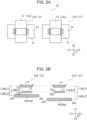
- FIG. 2A is a plan view schematically illustrating an important portion of a current sensor 20 according to a modification
- FIG. 2B is a cross-sectional view thereof.
- each of a large-current unit 21A and a small-current unit 21B (units 21) of a current sensor 20 has a shield 24 in a form of a flat plate only including a base 24a instead of the shield 14 including the standing portions 14b.
- the current sensor 20 is different from the current sensor 10 in this configuration.
- each of the units 21 has a flat shield 24 instead of the shield 14 having a U-shaped cross section in a YZ plane.
- a distance L1A in the large-current unit 21A is the same as a distance L1B in the small-current unit 21B.
- a distance L2A in the large-current unit 21A is larger than a distance L2B in the small-current unit 21B.
- a distance L3 between the magnetic sensor 13 and an end portion 24e of the shield 24 is larger than a distance L3B in the small-current unit 21B.
- a range of current measurable by the large-current unit 21A of the current sensor 20 is increased, and a detection error of the current may be reduced.
- the shield 24 is disposed on an opposite side of the magnetic sensor 13 with the bus bar 12 interposed therebetween is illustrated as a configuration of the units 21 in FIG. 2
- the bus bar 12 and the magnetic sensor 13 may be disposed between a pair of shields 24 arranged to face each other in the second direction (Y-axis direction).
- FIG. 3 is a cross-sectional view schematically illustrating the positional relationship of an important portion of a current sensor 30.
- the current sensor 30 has a large-current unit group 31 and a small-current unit group 32 which are arranged next to each other in a third direction.
- the large-current unit group 31 has a plurality of large-current units 11A arranged at intervals a1 in the third direction (Z-axis direction).
- the small-current unit group 32 has a plurality of small-current units 11B arranged at intervals a2 in the third direction.
- one of the large-current units 11A and one of the small-current units 11B which are adjacent to each other i.e., one of the large-current units 11A of the large-current unit group 31 which is positioned closest to the adjacent small-current unit group 32 and one of the small-current units 11B of the small current unit group 32 which is positioned closest to the adjacent large-current unit group 31 are arranged at an interval b in the third direction.
- one of the large-current units 11A which is positioned at an end on a Z1 side in a Z-axis direction which is the third direction and one of the small-current units 11B which is positioned at an end on a Z2 side in the Z-axis direction are arranged at the interval b in the third direction.
- the term "interval" means a distance between a center point and a center point of the units 11 arranged next to each other in the third direction.
- bus bars 12 of the large-current units 11A are arranged on a plane A.
- bus bars 12 of the small-current units 11B are arranged on a plane B.
- the planes A and B are on the same plane, and both are located in an XZ plane.
- the large-current unit group 31 includes the three large-current units 11A and the small-current unit group 32 includes the three small-current units 11B, the numbers of the units 11A and units 11B may be 1, 2, 4 or more.
- the interval b between one of the large-current units11A and one of the small-current units 11B is larger than the intervals a1 of the large-current units 11A and is larger than the intervals a2 of the small-current units 11B. That is, the interval b between the large-current unit 11A and the small-current unit 11B, which are adjacent across a boundary between the large-current unit group 31 and the small-current unit group 32, is wider than the intervals a1 and a2 of the units 11 belonging to the same unit groups.
- the influence from the adjacent unit 11, in particular, influence on the magnetic sensor 13 of the adjacent small-current unit 11B due to the current flowing through the bus bar 12 of the large-current unit 11A, may be suppressed, and a detection error of the current may be reduced.
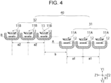
- FIG. 4 is a cross-sectional view schematically illustrating the positional relationship of an important portion of a current sensor 40 according to a modification.
- the current sensor 40 includes a large-current unit group 31 and a small-current unit group 32.
- the magnitude relationship among intervals a1 in a Z-axis direction of large-current units 11A, intervals a2 in the Z-axis direction of small-current units 11B, and an interval b in the Z-axis direction of one of the large-current units 11A and one of the small-current units 11B which are adjacent to each other is the same as that of the current sensor 30.
- a configuration in which a plane A having bus bars 12 of the large-current units 11A arranged thereon and a plane B having bus bars 12 of the small-current units 11B arranged thereon are different from each other is different from that of the current sensor 30.
- the current sensor 40 illustrated in FIG. 4 has an interval b which is larger than the intervals a1 and the intervals a2.
- the interval b may be equal to one or both of the intervals a1 and a2.
- positions of the planes A and B in a Y-axis direction may be opposite to those in FIG. 4 .
- the plane A in which the bus bars 12 of the large-current units 11A are arranged is preferably located on an opposite side (Y2 side) of the magnetic sensors 13 of the small-current units 11B relative to the plane B in which the bus bars 12 of the small-current unit 11B are arranged, as illustrated in FIG. 4 . Since the bus bars 12 of the large-current units 11A are arranged on the opposite side of the magnetic sensors 13 of the small-current units 11B, a distance between the bus bars 12 of the large-current units 11A and the magnetic sensors 13 of the small-current units 11B may be increased. Therefore, an influence of the magnetism of the bus bar 12 of the large-current unit 11A on the adjacent small-current unit 11B may be suppressed.
- FIG. 5A is a plan view schematically illustrating the positional relationship of an important portion of a current sensor unit 50 according to a third embodiment
- FIG. 5B is a cross-sectional view thereof.
- large-current units 11A are designated as 11A1, 11A2, and 11A3
- small-current units 11B are designated as 11B1, 11B2, and 11B3 when viewed from a Z1 side to a Z2 side in a Z axis direction.
- the adjacent large-current units 11A1 and 11A2 and the adjacent large-current units 11A2 and 11A3 are not arranged on the same straight line.
- the same straight line is parallel to the Z-axis direction (third direction).
- the large-current units 11A1 and 11A3 are arranged on opposite sides on a straight line C parallel to the Z axis, and the large-current unit 11A2 is arranged between the units 11A1 and 11A3 on a straight line D parallel to the straight line C.
- the small-current units 11B1, 11B2, and 11B3 arranged in the Z-axis direction, the small-current units 11B1 and 11B2 which are adjacent to each other are not arranged on the same straight line, and the small-current units 11B2 and 11B3 which are adjacent to each other are not arranged on the same straight line.
- the small-current units 11B1 and 11B3 are arranged on opposite sides on the straight line C parallel to the Z axis, and the small-current unit 11B2 is arranged between the units 11B1 and 11B3 on the straight line D parallel to the straight line C.
- both the large-current unit group 51 and the small-current unit group 52 when a magnitude of the current flowing through the bus bars 12 of the adjacent units 11 is the same, the adjacent units 11 are not arranged on the same straight line extending in the Z-axis direction. With this configuration, sizes of the large-current unit group 51 and the small-current unit group 52 in the Z-axis direction may be reduced.
- the sizes of the large-current unit group 51 and the small-current unit group 52 in the Z-axis direction may be reduced, and sizes thereof in an X-axis direction may also be reduced.
- the large-current unit 11A1 and the small-current unit 11B3 are adjacent units 11 having different magnitudes of current flowing through the respective bus bars 12, and are arranged on the same straight line C extending in the Z-axis direction.
- shields 14 (standing portions 14b) of the large-current unit 11A1 and the small-current unit 11B3 are arranged in a duplex manner between a bus bar 12 of the large-current unit 11A1 and a magnetic sensor 13 of the small-current unit 11B3 in the Z direction. Therefore, influence of a magnetism caused by current flowing through the bus bar 12 of the large-current unit 11A1 on the magnetic sensor 13 of the small-current unit 11B3 may be suppressed by the shield 14.
- the shield 14 when the shield 14 is in a form of a flat plate constituted only by a base 14a without standing portions 14b, the bus bar 12 and the magnetic sensor 13 may be arranged between a pair of shields 24 (base 14a) so that influence of magnetism caused by the current flowing through the bus bar 12 of the large-current unit 11A1 on the magnetic sensor 13 of the small-current unit 11B3 may be efficiently suppressed.
- the bus bars 12 of the large-current units 11A1, 11A2, and 11A3 of the large-current unit group 51 are arranged on a plane A parallel to an XZ plane.
- the bus bars 12 of the small-current units 11B1, 11B2, and 11B3 of the small-current unit group 52 are arranged on a plane B parallel to the XZ plane.
- the planes A and B are the same plane, a size of the current sensor 50 in a Y-axis direction may be reduced.
- the planes A and B may not be the same plane.
- FIG. 6A is a plan view schematically illustrating the positional relationship of an important portion of a current sensor 60 according to a modification
- FIG. 6B is a cross-sectional view thereof.
- the current sensor 60 is different from the current sensor 50 in a configuration in which a large-current unit 11A is provided in place of the large-current unit group 51.
- a small-current unit 11B3 adjacent to the large-current unit 11A on a Z1 direction side, a small-current unit 11B1 adjacent to the large-current unit 11A on the Z1 direction side, and the large-current unit 11A are arranged on the same straight line C extending in the Z-axis direction.
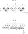
- FIG. 7A is a plan view schematically illustrating the positional relationship of an important portion of a current sensor 70 according to another modification
- FIG. 7B is a cross-sectional view thereof.
- the current sensor 70 is different from the current sensor 50 of FIG. 5 in a configuration in which a medium-current unit group 53 is further provided between a large-current unit group 51 and a small-current unit group 52.
- the medium-current unit group 53 includes medium-current units 11C in which current of a magnitude between a current value of current flowing through large-current units 11A and a current value of current flowing through small-current units 11B flows.
- the current sensor 70 includes, in addition to the large-current unit group 51 and the small-current unit group 52, the medium-current unit group 53, a range of measurable current is widened, and therefore, the current sensor 70 including the medium-current unit group 53 is more suitably used depending on a usage.
- each of the medium-current units 11C includes a bus bar 12, a magnetic sensor 13, and a shield 14.
- the relative positional relationship of the components included in each of the medium-current unit 11C is the same as those of the large-current units 11A and the small-current units 11B.
- Each of the medium-current units 11C has a distance L1 (refer to FIG. 1B ) between the bus bar 12 and the magnetic sensor 13 in a Y-axis direction equal to the large-current units 11A and the small-current units 11B.
- the medium-current unit 11C has a distance L2 between the bus bar 12 and the shield 14 in the Y-axis direction (refer to FIG. 1B ) smaller than those of the large-current units 11A and larger than that of the small-current units 11B.
- the units 11 having different current values of current flowing through the bus bars 12 are arranged on the same straight line extending in a Z-axis direction.
- the large-current unit 11A and the medium-current unit 11C which are adjacent to each other in the Z-axis direction are arranged on the same straight line C
- the small-current unit 11B and the medium-current unit 11C which are adjacent to each other in the Z-axis direction are arranged on the same straight line C.
- a unit with a distance L1 of 2.6 mm and a distance L2 of 1.2 mm was measured in the same manner as the first example.
- Table 2 shows results of a magnetic flux density and a shield inner magnetic flux density measured and detected in the first example and the first comparative example.
- FIG. 9 is a graph of results of measurement performed by changing a direction of measurement target current flowing in the bus bar 12 in the first example. As illustrated in FIG. 9 , an error of a measured current value was the same regardless of a magnitude of a detected current.
- a measurement error caused by current flowing through a bus bar 12 of an adjacent unit 11 was measured.
- a large-current unit group 51 and a small-current unit group 52 the following configurations were used.
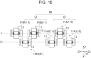
- the current sensor 80 For a current sensor 80 illustrated in FIG. 10 , a measurement error caused by current flowing through a bus bar 12 of an adjacent unit 11 was measured.
- the current sensor 80 is different from the current sensor 50 of the second example in that the current sensor 80 includes a large-current unit 81 in place of the large-current unit group 51.
- large-current units 11A Only the arrangement of large-current units 11A is different between the large-current unit group 81 and the large-current unit group 51. Specifically, as illustrated in FIG. 10 , large-current units 11A1 and 11A3 are arranged on opposite sides on a straight line D, and a large-current unit 11A2 is disposed on a straight line C between the large-current units 11A1 and 11A3.
- the present invention is useful as a current sensor for measuring currents of different sizes in electric vehicles and hybrid vehicles having motors.
Landscapes
- Physics & Mathematics (AREA)
- General Physics & Mathematics (AREA)
- Measuring Instrument Details And Bridges, And Automatic Balancing Devices (AREA)
Applications Claiming Priority (2)
| Application Number | Priority Date | Filing Date | Title |
|---|---|---|---|
| JP2022016502 | 2022-02-04 | ||
| PCT/JP2022/045525 WO2023149082A1 (ja) | 2022-02-04 | 2022-12-09 | 電流センサ |
Publications (2)
| Publication Number | Publication Date |
|---|---|
| EP4474833A1 true EP4474833A1 (de) | 2024-12-11 |
| EP4474833A4 EP4474833A4 (de) | 2026-01-14 |
Family
ID=87552067
Family Applications (1)
| Application Number | Title | Priority Date | Filing Date |
|---|---|---|---|
| EP22924986.7A Pending EP4474833A4 (de) | 2022-02-04 | 2022-12-09 | Elektrischer stromsensor |
Country Status (4)
| Country | Link |
|---|---|
| US (1) | US20240361362A1 (de) |
| EP (1) | EP4474833A4 (de) |
| JP (1) | JP7579466B2 (de) |
| WO (1) | WO2023149082A1 (de) |
Family Cites Families (9)
| Publication number | Priority date | Publication date | Assignee | Title |
|---|---|---|---|---|
| JPH0875817A (ja) * | 1994-08-31 | 1996-03-22 | Advantest Corp | 電圧印加電流測定装置 |
| JP2013113630A (ja) * | 2011-11-25 | 2013-06-10 | Yazaki Corp | 電流検出装置 |
| JP6477089B2 (ja) | 2014-05-23 | 2019-03-06 | 株式会社デンソー | 電流センサ付バスバーモジュール |
| JP2016148620A (ja) | 2015-02-13 | 2016-08-18 | 株式会社フジクラ | 電流センサ |
| JP6690027B2 (ja) * | 2017-02-17 | 2020-04-28 | アルプスアルパイン株式会社 | 電流センサ |
| JP6890112B2 (ja) * | 2018-11-15 | 2021-06-18 | 矢崎総業株式会社 | 電流検出装置 |
| JP2020115104A (ja) * | 2019-01-18 | 2020-07-30 | 株式会社デンソー | 電流センサ |
| DE112020004828T5 (de) * | 2019-10-08 | 2022-06-15 | Alps Alpine Co., Ltd. | Stromdetektionsvorrichtung |
| DE112021003837T5 (de) * | 2020-07-14 | 2023-05-25 | Alps Alpine Co., Ltd. | Stromerfassungsvorrichtung |
-
2022
- 2022-12-09 WO PCT/JP2022/045525 patent/WO2023149082A1/ja not_active Ceased
- 2022-12-09 EP EP22924986.7A patent/EP4474833A4/de active Pending
- 2022-12-09 JP JP2023578400A patent/JP7579466B2/ja active Active
-
2024
- 2024-07-09 US US18/767,125 patent/US20240361362A1/en active Pending
Also Published As
| Publication number | Publication date |
|---|---|
| JPWO2023149082A1 (de) | 2023-08-10 |
| US20240361362A1 (en) | 2024-10-31 |
| WO2023149082A1 (ja) | 2023-08-10 |
| EP4474833A4 (de) | 2026-01-14 |
| JP7579466B2 (ja) | 2024-11-07 |
Similar Documents
| Publication | Publication Date | Title |
|---|---|---|
| US9069016B2 (en) | Current sensor | |
| EP2851691B1 (de) | Stromsensor | |
| US9435829B2 (en) | Current sensor | |
| US10060953B2 (en) | Current sensor | |
| JP2013238580A (ja) | 電流センサ | |
| US6940265B2 (en) | Device, ammeter and motor vehicle | |
| JP5659389B2 (ja) | 電流センサ | |
| EP2515125A2 (de) | Stromsensor mit Magnetkern | |
| US9335349B2 (en) | Current sensor | |
| CN113495183A (zh) | 电流传感器及其制造方法、电控制装置、以及电流传感器的设计方法 | |
| JP2017133942A (ja) | 電流センサ | |
| US11209466B2 (en) | Current sensor | |
| JP6384677B2 (ja) | 電流センサ | |
| JP5704347B2 (ja) | 電流センサ | |
| EP4474833A1 (de) | Elektrischer stromsensor | |
| JP6671986B2 (ja) | 電流センサおよびその製造方法 | |
| US20240369600A1 (en) | Battery system and hybrid current sensor therefor | |
| JP2012063285A (ja) | 電流センサ | |
| WO2025120986A1 (ja) | 電流センサ | |
| KR20230044818A (ko) | 영상전류 센서 및 그 보정 방법 | |
| JP2014006115A (ja) | 電流センサ |
Legal Events
| Date | Code | Title | Description |
|---|---|---|---|
| STAA | Information on the status of an ep patent application or granted ep patent |
Free format text: STATUS: THE INTERNATIONAL PUBLICATION HAS BEEN MADE |
|
| PUAI | Public reference made under article 153(3) epc to a published international application that has entered the european phase |
Free format text: ORIGINAL CODE: 0009012 |
|
| STAA | Information on the status of an ep patent application or granted ep patent |
Free format text: STATUS: REQUEST FOR EXAMINATION WAS MADE |
|
| 17P | Request for examination filed |
Effective date: 20240710 |
|
| AK | Designated contracting states |
Kind code of ref document: A1 Designated state(s): AL AT BE BG CH CY CZ DE DK EE ES FI FR GB GR HR HU IE IS IT LI LT LU LV MC ME MK MT NL NO PL PT RO RS SE SI SK SM TR |
|
| DAV | Request for validation of the european patent (deleted) | ||
| DAX | Request for extension of the european patent (deleted) | ||
| A4 | Supplementary search report drawn up and despatched |
Effective date: 20251216 |
|
| RIC1 | Information provided on ipc code assigned before grant |
Ipc: G01R 15/20 20060101AFI20251210BHEP Ipc: G01R 19/00 20060101ALI20251210BHEP Ipc: G01R 1/18 20060101ALI20251210BHEP Ipc: G01R 1/07 20060101ALI20251210BHEP |