EP4472066A1 - Rahmenmontierter anschlusskasten für solarzellenmodule - Google Patents
Rahmenmontierter anschlusskasten für solarzellenmodule Download PDFInfo
- Publication number
- EP4472066A1 EP4472066A1 EP23177131.2A EP23177131A EP4472066A1 EP 4472066 A1 EP4472066 A1 EP 4472066A1 EP 23177131 A EP23177131 A EP 23177131A EP 4472066 A1 EP4472066 A1 EP 4472066A1
- Authority
- EP
- European Patent Office
- Prior art keywords
- solar cell
- cell module
- junction box
- frame
- interconnector
- Prior art date
- Legal status (The legal status is an assumption and is not a legal conclusion. Google has not performed a legal analysis and makes no representation as to the accuracy of the status listed.)
- Withdrawn
Links
Images


Classifications
-
- H—ELECTRICITY
- H02—GENERATION; CONVERSION OR DISTRIBUTION OF ELECTRIC POWER
- H02S—GENERATION OF ELECTRIC POWER BY CONVERSION OF INFRARED RADIATION, VISIBLE LIGHT OR ULTRAVIOLET LIGHT, e.g. USING PHOTOVOLTAIC [PV] MODULES
- H02S40/00—Components or accessories in combination with PV modules, not provided for in groups H02S10/00 - H02S30/00
- H02S40/30—Electrical components
- H02S40/34—Electrical components comprising specially adapted electrical connection means to be structurally associated with the PV module, e.g. junction boxes
-
- H—ELECTRICITY
- H02—GENERATION; CONVERSION OR DISTRIBUTION OF ELECTRIC POWER
- H02S—GENERATION OF ELECTRIC POWER BY CONVERSION OF INFRARED RADIATION, VISIBLE LIGHT OR ULTRAVIOLET LIGHT, e.g. USING PHOTOVOLTAIC [PV] MODULES
- H02S30/00—Structural details of PV modules other than those related to light conversion
- H02S30/10—Frame structures
-
- Y—GENERAL TAGGING OF NEW TECHNOLOGICAL DEVELOPMENTS; GENERAL TAGGING OF CROSS-SECTIONAL TECHNOLOGIES SPANNING OVER SEVERAL SECTIONS OF THE IPC; TECHNICAL SUBJECTS COVERED BY FORMER USPC CROSS-REFERENCE ART COLLECTIONS [XRACs] AND DIGESTS
- Y02—TECHNOLOGIES OR APPLICATIONS FOR MITIGATION OR ADAPTATION AGAINST CLIMATE CHANGE
- Y02E—REDUCTION OF GREENHOUSE GAS [GHG] EMISSIONS, RELATED TO ENERGY GENERATION, TRANSMISSION OR DISTRIBUTION
- Y02E10/00—Energy generation through renewable energy sources
- Y02E10/50—Photovoltaic [PV] energy
Definitions
- the disclosure relates to a solar cell module and a method for manufacturing a solar cell module.
- a solar cell module may also be called a photovoltaic module.
- junction boxes are required to allow for electrically connecting solar cell modules to a power grid.
- the junction box is provided on a backside of the solar cell module laminate comprising the solar cells.
- solar cell modules also require a frame to increase the mechanical stability of the solar cell module laminate and to allow for mounting the solar cell module on a support structure, for example, a roof of a building.
- US 9,337,771 B2 provides a mounting bracket for a junction box utilized for a solar cell, a junction box with the mounting bracket, and the solar cell module.
- the mounting bracket for the junction box comprises a joint arm, an insert strip, and a hook.
- the insert strip comprises a first elastic strip connecting with the joint arm, a joint strip connecting with the first elastic strip and bending towards the joint arm, and a second elastic strip connecting with the joint arm.
- the insert strip is used for inserting into the frame. At least one of the first and the second elastic strips of the insert strip comprise a first elastic block.
- the proposed mounting bracket requires additional handling during assembly of the known solar cell module. This may render manufacturing more complex and costly.
- WO 2011/139648 A1 relates to a junction box for use in a solar cell module, a frame comprising the junction box, and a solar cell module comprising the junction box.
- the junction box may form a part of a section of the frame or the corner joints of the frame and extends along the edge of the cell panel.
- the junction box comprises: a body which comprises a clamping part and a containment part adapted for clamping the edge of the cell panel; a wiring board mounted in the containment part and having a connection line with at least one switching diode; a male connection cable connected to one connection of the connection line and comprising a plug; and a female connection cable connected to the other connection of the connection line and comprising a socket.
- junction box as part of the frame may result in a less rigid frame.
- Examples relate to a method for manufacturing a solar cell module.
- the method comprises providing a solar cell module laminate, wherein the solar cell module laminate includes a solar cell, a connecting wire having a contacting portion electrically contacting a solar cell contact of the solar cell, and a collecting portion of an interconnector crossing the connecting wire and electrically contacting the connecting wire, wherein the solar cell, the connecting wire and the collecting portion are arranged between a front side encapsulation layer (also simply referred to as encapsulant) a front side glass, a back side encapsulation layer and/or a back side protection layer; providing a frame, providing a junction box, wherein the junction box comprises a housing and a conductor.
- the method further includes at least partially accommodating the junction box in a recess of the frame such that a contacting interface between the conductor and an connection portion of the interconnector is arranged in a plane parallel to the solar cell.
- the method may optionally further include contactless materially bonding the conductor to the connection portion of the interconnector.
- materially bonding may not be required.
- a spring force may be used to fix the conductor to the connection portion of the interconnector (spring-force mediated contact).
- the conductor of the junction box can be formed as a spring (e.g., leaf spring; arc-shaped) and thereby can be biased against the interconnector.
- a spring may be arranged adjacent to the conductor to push the conductor against the interconnector.
- a shape bias can be provided at the conductor and/or the interconnector to fix both elements so that they are in electrical contact with each other. In some scenarios, it is possible to combine materially bonding (specifically contactless materially bonding) with electrically contacting using a spring force.
- Said method may allow for reliably manufacturing a solar cell module.
- the junction box may be attached to the frame before arranging the solar cell module laminate in the frame.
- the solar cell module laminate may be arranged in the frame after arranging the junction box on the solar cell module laminate.
- junction box is arranged in the frame after arranging the solar cell module laminate in the frame.
- the energy source is not in direct solid-state contact with the bonding target site. Accordingly, it is possible to execute the contactless material bonding even after attaching the junction box to the frame and after arranging the solar cell module laminate in the frame.
- the energy source can be located outside of the housing of the junction box. This simplifies the attachment process. In particular, it becomes possible to first attach the junction box to the frame and then subsequently arrange the solar cell module laminate in the frame; then the contactless materially bonding can be executed.
- Contactless materially bonding the conductor to the connection portion of the interconnector may comprise at least one of induction soldering, induction welding, laser welding, and/or electron beam welding. Contactless materially bonding may reduce the need to have current conducting portions of the solar cell module close to the outer surface of the solar cell module, where they may have to be covered with insulating material afterwards.
- the mechanical mechanism automatically establishes the contact when both the junction box as well as the solar cell module laminate are attached to the frame.
- the interconnector is not required to be laterally led out of the solar cell module laminate; i.e., a connection portion of the interconnector is not folded back on an outer surface of the solar cell module laminate through openings in one or more layers at the backside outer surface of the solar cell module laminate (e.g., encapsulant and/or backsheet and/or backside glass).
- a connection portion of the interconnector is not folded back on an outer surface of the solar cell module laminate through openings in one or more layers at the backside outer surface of the solar cell module laminate (e.g., encapsulant and/or backsheet and/or backside glass).
- two portions of the interconnector are vertically offset (in a depth direction between front surface and back surface of the solar cell module laminate) is not required.
- Leading the connection portion of the interconnector out of the solar cell module laminate is not required; this simplifies the manufacturing process.
- an opening may be provided in one or more outer layers of the solar cell module laminate, the opening arranged so that the connection portion of the interconnector (otherwise buried underneath the one or more outer layers, e.g., encapsulant - typically an adhesive foil - and a back-sheet and/or a backside glass) is exposed to the outside of the solar cell module laminate and can be contacted by a conductor of the junction box through the opening.
- encapsulant - typically an adhesive foil - and a back-sheet and/or a backside glass
- a single-layered interconnector can be used that has a flat connection portion that extends in the plane parallel to the surface of the solar cell module laminate. This simplifies the manufacturing process and enables compact dimensions of the solar cell module laminate.
- An opening can be provided in the respective outer layer of the solar cell module so that the connection portion of the interconnector can be contacted by respective conductors of the junction box.
- Such opening can extend through one or more layers of the solar cell module laminate (e.g., encapsulant and backsheet or backside glass) underneath which the interconnector is buried.
- the solar cell module may be manufactured according to a method as previously described.
- the solar cell module comprises a solar cell module laminate including a solar cell, a connecting wire having a contacting portion electrically contacting a solar cell contact of the solar cell, and a collecting portion of an interconnector crossing the connecting wire and electrically contacting the connecting wire, wherein the solar cell, the connecting wire and the collecting portion are arranged between a front side encapsulation layer and a back side encapsulation layer, a frame, a junction box, wherein the junction box comprises a housing and a conductor, wherein the junction box is at least partially accommodated in a recess of the frame, wherein the conductor is in electrical contact with a connection portion of the interconnector, wherein a contacting interface between the conductor and the connection portion is arranged in a plane parallel to the solar cell, wherein the junction box abuts the solar cell module laminate and the frame.
- the housing may be lid free. This may render the construction of the housing simpler. Further, it may reduce the risk of intrusion of humidity in the housing and, thus, prolong the lifetime of the solar cell module.
- Examples may prescribe that the housing comprises a collar facing the solar cell module laminate.
- the collar may enhance the distance to current conducting elements of the solar cell module.
- the housing and the solar cell module laminate may surround the conductor. Hence, the conductor may be sealed from the ambient.
- the solar cell module laminate may be held in a groove of the frame, wherein an opening of the groove is directed to a centre of the solar cell module.
- the frame may comprise an extruded frame bar. This may render the solar cell module suitable for production in large numbers.
- the frame may be made from aluminium. Aluminium may be suitable material due to its favourable relation between mechanical strength and weight.
- At least portions of the frame may be formed by injection moulding. Forming at least portions of the frame by injection moulding may render manufacture of the solar cell module particularly suitable for mass production.
- the frame may be made from a polymer.
- the frame may be made from a fibre reinforced plastic.
- the recess for accommodating the junction box may be formed by milling, water jet cutting or laser cutting.
- the frame may be configured to impede a movement of the junction box in a direction perpendicular to the solar cell module laminate. This may reduce the risk that the junction box becomes separated from the solar cell module laminate during the lifetime of the solar cell module.
- the frame may be configured to impede a movement of junction box in one or both directions parallel to the solar cell module laminate.
- the frame may also be configured to impede a rotation of the junction box with respect to the solar cell module laminate.
- the junction box may be attached to the frame.
- the junction box may be held in the frame in an interlocking manner.
- the junction box may be held in the frame using a snap-fit, in particular a cantilever snap-fit.
- the housing comprises a cantilever for establishing the cantilever snap fit.
- the housing may comprise a protrusion for fixing the junction box in the frame in an interlocking manner.
- the housing comprises a filling opening for introducing a sealant between the junction box and the solar cell module laminate.
- This may allow for providing sealant in the cavity formed between the junction box and the surface of the solar cell module laminate, after the junction box has been put into the final position with respect to the solar cell module laminate. This may avoid smearing of sealant during manufacturing of the solar cell module laminate.
- the sealant may provide additional electrical insulation.
- the housing may further comprise a vent opening. The vent opening may allow air to move out of the cavity when the sealant is provided through the filling opening. Hence, the formation of bubbles may be avoided.
- the housing may be made from an insulating material, in particular from a polymer.
- the housing may be made by injection moulding.
- the conductor may be fixed in the housing during injection moulding.
- a plane surface of the housing facing the solar cell module laminate may be aligned with a plane surface of the frame facing the solar cell module laminate.
- the plane surface of the housing may be aligned with a plane surface of the groove of the frame in which the solar cell module laminate is arranged.
- the junction box may comprise a bridging element, in particular a by-pass diode.
- solar cell module may comprise a connection cable connected to the conductor of the junction box.
- the diode may, in particular, be arranged in a part of the junction box that is offset from the solar cell module laminate. Thereby, heat flow from the diode to the solar cell module laminate and the solar cells can be reduced.
- the techniques employ a junction box that is arranged in a recess in a frame of the solar cell module. This renders the solar cell module robust, because the junction box is less exposed than in other implementations in which the junction box is attached offset from the frame to the backside surface of the solar cell module laminate.
- junction box the solar cell module laminate and the frame enable efficient, simple, and high-throughput manufacturing. Fewer manufacturing steps are required. Robust solar cell modules are obtained that provide a reliable electrical connection between the conductor in the junction box and the solar cells of the solar cell module laminate. Heat transfer from one or more by-pass diodes in the junction box to the solar cell module laminate is reduced.
- FIG. 1A shows a portion of a solar cell module 1000.
- the solar cell module 1000 comprises a solar cell module laminate 1100, a frame 1200, and a junction box 1300 having a housing 1310.
- the solar cell module laminate 1100 includes at least one solar cell (not shown), connecting wires 1101 having a contacting portion electrically contacting a solar cell contact of the solar cell, and an interconnector 1102, wherein a collection portion of the interconnector 1102 crosses the connecting wires 1101 and electrically contacts the connecting wires 1101 (the connecting wires 1101 and the interconnector 1102 are shown embedded into the solar cell module laminate 1100).
- the solar cell, the connecting wire 1101, and the collecting portion are arranged between a front side encapsulation layer and a back side encapsulation layer (the front surface 1198 and the back surface 1999 are shown).
- the solar cell module laminate 1100 may further include a front glass and a back sheet or a back glass (not shown in Fig. 1 ).
- the junction box 1300 comprises the housing 1310 and a conductor 1320 and is at least partially accommodated in a recess of the frame 1200 (see Fig. 3 ).
- the conductor 1320 is in electrical contact with a connection portion of the interconnector 1102. This electrical contact can be firmly established, e.g., by a spring force and/or by using contactless materially bonding, as will be explained later on in further detail.
- a contacting interface between the conductor 1320 and the connection portion of the interconnector 1102 is arranged in a plane parallel to the solar cell, i.e., the solar cell module laminate.
- One or more layers of the solar cell module laminate 1100 beneath which the interconnector 1102 is buried e.g., a backside encapsulation layer / encapsulant and a backsheet or backside glass
- a backside encapsulation layer / encapsulant and a backsheet or backside glass have an opening 1329 in the region of the connection portion; this exposes the connection portion of the interconnector 1102 and thus enables the direct electrical contact between the conductor 1320 and the interconnector 1102 (i.e., without a need of folding back lateral end portions of the interconnector 1102 protruding from the sides of the solar cell module laminate 1110 to be exposed at the back side of the solar cell module laminate 1110 as in prior-art solutions).
- the junction box 1300 abuts the solar cell module laminate 1100 and the frame 1200.
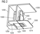
- Fig. 2 shows the junction box 1300 attached to the frame 1200 before arranging the solar cell module laminate 1100 in the frame 1200.
- the solar cell module laminate 1100 may be later held in a groove 1220 of the frame 1200, wherein an opening of the groove 1220 is directed to a centre of the solar cell module 1000.
- the groove 1220 is arranged offset from the recess in which the junction box 1300 is arranged.
- the frame 1200 may comprise an extrude frame bar and may be made from aluminium for example.
- the recess 1210 (see Fig. 3 ) for accommodating the junction box 1300 may be formed by milling, water jet cutting, or laser cutting.
- the frame 1200 is configured to impede a movement of the junction box 1300 in a direction perpendicular to the solar cell module laminate 1100.
- the frame 1200 is configured to impede a movement of the junction box 1300 in both directions parallel to the solar cell module laminate 1100 ("in-plane movement") and, further, impede a rotation of the junction box 1300 with respect to the solar cell module laminate 1100.
- the junction box 1300 is attached to the frame 1200 in an interlocking manner using a snap-fit, more specifically a cantilever snap-fit.
- the housing 1310 of the junction box 1300 comprises a cantilever 1311 at a portion 1501 for attaching the junction box 1300 to the frame 1200 (see Fig.
- the housing 1310 comprises protrusions 1312, 1313 for fixing the junction box 1300 in the frame 1200 in an interlocking manner.
- the protrusion 1312 may be guided through the passage 1211.
- the junction box 1300 may be pushed downwards (towards the groove 1220), until the upper part of the housing 1310 is pushed into the recess 1210 and the cantilever 1311 snaps-in behind the wall 1212 of the frame 1200.
- the cantilever 1311 in combination with the protrusions 1312 prevents disengagement of the junction box 1300 from the frame 1200.
- junction box 1300 is "L-shaped" (see Fig. 3 ).
- a respective method includes aligning protrusions of a junction box with guide features arranged at a side wall of a recess of a frame of a solar cell module, pushing the junction box into the recess in a first direction, upon the protrusions having passed the side wall of the recess, pushing the junction box into the recess in a second direction, until a snap fit attachment is established by a cantilever.
- the cantilever is provided with the junction box or the frame.
- a plane surface 1314 of the housing 1310 and plane surface 1221 of the frame 1200, in particular a plane surface 1221 of the groove 1220 of the frame 1200 may be aligned, e.g., a flush alignment. This may facilitate inserting the solar cell module laminate 1100 into the groove 1220 of the frame 1200.
- the plane surfaces 1221, 1314 may face the solar cell module laminate 1100 after insertion of the solar cell module laminate 1100 into the groove 1220.
- the conductor 1320 may protrude from the plane surface 1314 of the housing 1310.
- the conductor 1320 may exert a spring force on the connection portion of the interconnector 1102 of the solar cell module laminate 1100 (the direction of the spring force is illustrated by the dotted arrows in Fig. 1B ). This may improve the electrical connection between the conductor 1320 and the interconnector 1102.
- the respective portion of the conductor 1320 can be formed as a leaf spring.
- a separate spring e.g., a coil spring, or an elastic material can be provided at a side of the conductor 1320 opposite to the interconnector 1102, to thereby push the conductor 1320 against the interconnector 1102.
- the spring force may allow for removing the need of materially bonding the conductor 1320 and the interconnector 1102.
- a collar 1315 of the housing 1310 may be provided, to increase the creepage distance between the environment and current conducting portions of the solar cell module 1000, in particular to the contacting interface between the conductor 1320 and the connection portion of the interconnector 1102.
- the housing 1310 may comprise a filling opening (not shown) for introducing a sealant between the junction box 1300 and the solar cell module laminate 1100.
- the sealant may be introduced in the cavity formed by the housing 1310 and the solar cell module laminate 1100 after assembling the solar cell module 1000.
- the sealant may reduce the risk that moisture enters said cavity.
- the sealant may also provide additional insulation of the current-conducting conductor 1320 and interconnector 1102.
- the housing 1310 may include a vent opening (not shown) allowing for air to escape, when sealant is introduced into the cavity via the filling opening.
- the solar cell module 1000 may further comprise a connection cable connected to the conductor of the junction box 1300.
- the junction box 1300 may further comprise a bridging element, in particular a by-pass diode.
- junction box 1300 that is integrated into the frame 1200 of a solar cell module 1000 instead of being attached to the back of the solar cell module laminate 1100 is proposed.
- the proposed junction box 1300 may either be plugged into the frame 1200 before the solar cell module laminate 1100 is arranged in the frame 1200.
- the conductor 1320 of the junction box 1300 may electrically contact the interconnector 1102 of the solar cell module laminate 1100.
- this electrical contact can be established using one or more of the following techniques: spring bias; induction soldering, induction welding, laser welding, and/or electron beam welding. All these techniques do not require that the contact between the conductor 1320 and the interconnector 1102 is exposed to the surrounding when establishing the electrical contact.
- the housing 1310 of the junction box 1300 may comprise a collar 1315 (or plate) at its base. Said collar 1315 covers the contacting interface between the conductor 1320 and the interconnector 1102. Further, the outer surface of the collar 1315 may ensure that required electrical creepage distances are maintained.
- the collar 1315 is typically made from plastic to provide insulation.
- connection portion of the interconnector 1102 a cut-out in the outer layer(s) (encapsulation layer, back-sheet, glass) of the solar cell module laminate 1100 may be required.
- the cut-out may ensure that connection portion of the interconnector 1102 is exposed before assembling the solar cell module 1000.
- the connection portion may be temporarily covered with an adhesive tape that does not leave any residues when removed.
- a sealant track (e.g., a silicone track) may be drawn in an approximately U-shape around the exposed connection portion of the interconnector 1102, wherein the opening of the U is arranged such that the conductor 1320 does not come into contact with the silicone track when inserting the solar cell module laminate 1100 in the groove 1220 of the frame 1200.
- An amount of frame sealant (e.g., silicone) in the groove 1220 of the frame may be chosen such that when the solar cell module laminate 1100 is inserted into the frame 1200, the displace frame sealant closes the opening of the U. This may ensure that no water or other substances from the environment reach the contacting interface between the interconnector 1102 and the conductor 1320.
- the proposed approach significantly simplifies the solar cell module production.
- some known process steps are eliminated. This includes, e.g., leading the connection portion of the interconnector to the outside of the solar cell module laminate and folding back the same.
- welding can be dispensed with, because the electrical connection between the conductor in the junction box and the connection portion of the interconnector can be established by press fit/snap fit. Since the connection cable is no longer required to reach a junction box in the middle of the solar cell module, it has not to be fixed to the solar cell module during production.
- Arranging the junction box in the frame leaves more surface of the solar cell module which can be used for collecting light increasing the efficiency of the solar cell module compared to a solar cell module having the same outer dimensions, in particular, in case of a bifacial solar cell module. Moreover, the omission of a junction box in the middle of the solar cell module may improve the aesthetic appearance of the solar cell module.
- the examples described herein all have the advantage that bending of the end portion of the interconnector 1102 after laminating is avoided. This may severely facilitate the process for attaching the junction box. In case of a solar cell module including a front glass and a back sheet, end portions of the interconnector 1102 may no longer have to be led out of the solar cell module laminate 1100.
- the interconnector 1102 can be single-layered in the solar cell module laminate 1100.
- the connection portion of the interconnector 1102 is contacted by the conductor 1320 by forming an opening 1329 (cf. FIG. 1B ; dotted lines) in one or more layers of the solar cell module laminate 1100 after lamination, e.g., in the glass back sheet and an encapsulation layer.
- connection portion is arranged at ends of the interconnector 1102 in the illustrated example.
- certain prior-art solutions require end portions of the interconnector to be led out of the laminate and folded back to towards the back side of the laminate to establish the electrical contact with the conductor of the junction box.
- the additional step of having to bend and fold back end portions of the interconnector is dispensed with.
- such bending of the end portions of the interconnector is required to insert the bent portion through an opening in the back sheet when the back sheet is attached to the charge-carrier separation layer when forming the solar cell module laminate.
- the solar cell module described herein may use the design and dimension of the junction boxes.
- the same junction boxes may be used for solar cell modules comprising a front glass and a back sheet and solar cell modules comprising a front glass and a back glass.
- the proposed method for manufacturing the solar cell modules may have a higher process reliability. Passing angled end portions of interconnectors through openings of junction boxes and/or back sheets may be error prone. Errors may require complex post-processing and/or may reduce the yield of the solar cell modules.
- the positioning of the junction box with respect to the connection portions as proposed herein is less critical.
- a solar cell module may include, e.g., two or four junction boxes, arranged at different sides of the frame and possibly all configured as disclosed herein.
Landscapes
- Photovoltaic Devices (AREA)
Priority Applications (2)
| Application Number | Priority Date | Filing Date | Title |
|---|---|---|---|
| EP23177131.2A EP4472066A1 (de) | 2023-06-03 | 2023-06-03 | Rahmenmontierter anschlusskasten für solarzellenmodule |
| PCT/EP2024/065187 WO2024251657A1 (en) | 2023-06-03 | 2024-06-03 | Frame-attached junction box for solar cell modules |
Applications Claiming Priority (1)
| Application Number | Priority Date | Filing Date | Title |
|---|---|---|---|
| EP23177131.2A EP4472066A1 (de) | 2023-06-03 | 2023-06-03 | Rahmenmontierter anschlusskasten für solarzellenmodule |
Publications (1)
| Publication Number | Publication Date |
|---|---|
| EP4472066A1 true EP4472066A1 (de) | 2024-12-04 |
Family
ID=86692788
Family Applications (1)
| Application Number | Title | Priority Date | Filing Date |
|---|---|---|---|
| EP23177131.2A Withdrawn EP4472066A1 (de) | 2023-06-03 | 2023-06-03 | Rahmenmontierter anschlusskasten für solarzellenmodule |
Country Status (2)
| Country | Link |
|---|---|
| EP (1) | EP4472066A1 (de) |
| WO (1) | WO2024251657A1 (de) |
Citations (5)
| Publication number | Priority date | Publication date | Assignee | Title |
|---|---|---|---|---|
| US20060000504A1 (en) * | 2004-05-25 | 2006-01-05 | Guenter Feldmeier | Solar module having a connecting element |
| WO2010019749A2 (en) * | 2008-08-13 | 2010-02-18 | E. I. Du Pont De Nemours And Company | Method for installing a solar array incorporating hotovoltaic panels having keying structures |
| WO2011139648A2 (en) | 2010-04-26 | 2011-11-10 | E. I. Du Pont De Nemours And Company | Junction box, frame component and solar cell module |
| US9337771B2 (en) | 2013-01-18 | 2016-05-10 | Delta Electronics, Inc. | Mounting bracket for junction box, junction box with the mounting bracket, and solar cell module |
| DE102016211117A1 (de) * | 2016-06-22 | 2017-12-28 | Solarworld Innovations Gmbh | Solarmodul |
-
2023
- 2023-06-03 EP EP23177131.2A patent/EP4472066A1/de not_active Withdrawn
-
2024
- 2024-06-03 WO PCT/EP2024/065187 patent/WO2024251657A1/en not_active Ceased
Patent Citations (5)
| Publication number | Priority date | Publication date | Assignee | Title |
|---|---|---|---|---|
| US20060000504A1 (en) * | 2004-05-25 | 2006-01-05 | Guenter Feldmeier | Solar module having a connecting element |
| WO2010019749A2 (en) * | 2008-08-13 | 2010-02-18 | E. I. Du Pont De Nemours And Company | Method for installing a solar array incorporating hotovoltaic panels having keying structures |
| WO2011139648A2 (en) | 2010-04-26 | 2011-11-10 | E. I. Du Pont De Nemours And Company | Junction box, frame component and solar cell module |
| US9337771B2 (en) | 2013-01-18 | 2016-05-10 | Delta Electronics, Inc. | Mounting bracket for junction box, junction box with the mounting bracket, and solar cell module |
| DE102016211117A1 (de) * | 2016-06-22 | 2017-12-28 | Solarworld Innovations Gmbh | Solarmodul |
Also Published As
| Publication number | Publication date |
|---|---|
| WO2024251657A1 (en) | 2024-12-12 |
Similar Documents
| Publication | Publication Date | Title |
|---|---|---|
| JP5395802B2 (ja) | 太陽光発電ソーラーパネル用接続箱 | |
| EP2347451B1 (de) | Verbindungseinrichtung zum verbinden eines elektrischen leiters mit einem solarmodul | |
| CN101606295B (zh) | 用于太阳能模块的端子接线箱 | |
| JP4384241B1 (ja) | 端子ボックス及び太陽電池モジュール | |
| JP5441716B2 (ja) | 太陽光発電モジュール用接続箱 | |
| CN101834214B (zh) | 连接到太阳能模块的连接设备和具有该设备的太阳能模块 | |
| US8192233B2 (en) | Connector assembly for a photovoltaic module | |
| US20110186113A1 (en) | Terminal box for solar cell and attaching structure | |
| WO2010014941A1 (en) | Solar modules, solar module junction boxes, and methods for mounting junction boxes to solar modules | |
| CN102246320A (zh) | 用于连接到太阳能模块的连接装置以及具有该连接装置的太阳能模块 | |
| JP2001135847A (ja) | 半導体装置及びこれを備えた端子ボックス | |
| WO2010047225A1 (ja) | コネクタ | |
| EP4472066A1 (de) | Rahmenmontierter anschlusskasten für solarzellenmodule | |
| JP2001119058A (ja) | 端子ボックス及びその組立方法 | |
| CN104701399A (zh) | 太阳能电池模块、汽车天窗及制作太阳能电池模块的方法 | |
| EP4307393A1 (de) | Verfahren zum herstellen eines solarzellenmoduls und solarzellenmodul | |
| JP5306490B2 (ja) | 端子ボックス及び太陽電池モジュール | |
| JP5132646B2 (ja) | 端子ボックス及び太陽電池モジュール | |
| CN111418150B (zh) | 太阳能接线盒 | |
| JP2013138117A (ja) | 端子ボックス及び端子ボックスへのリード線の取付方法並びに太陽電池モジュール |
Legal Events
| Date | Code | Title | Description |
|---|---|---|---|
| PUAI | Public reference made under article 153(3) epc to a published international application that has entered the european phase |
Free format text: ORIGINAL CODE: 0009012 |
|
| STAA | Information on the status of an ep patent application or granted ep patent |
Free format text: STATUS: THE APPLICATION HAS BEEN PUBLISHED |
|
| AK | Designated contracting states |
Kind code of ref document: A1 Designated state(s): AL AT BE BG CH CY CZ DE DK EE ES FI FR GB GR HR HU IE IS IT LI LT LU LV MC ME MK MT NL NO PL PT RO RS SE SI SK SM TR |
|
| STAA | Information on the status of an ep patent application or granted ep patent |
Free format text: STATUS: THE APPLICATION IS DEEMED TO BE WITHDRAWN |
|
| 18D | Application deemed to be withdrawn |
Effective date: 20250605 |