EP4472058A1 - Motorantriebssystem - Google Patents
Motorantriebssystem Download PDFInfo
- Publication number
- EP4472058A1 EP4472058A1 EP23176345.9A EP23176345A EP4472058A1 EP 4472058 A1 EP4472058 A1 EP 4472058A1 EP 23176345 A EP23176345 A EP 23176345A EP 4472058 A1 EP4472058 A1 EP 4472058A1
- Authority
- EP
- European Patent Office
- Prior art keywords
- energy
- storage device
- drive system
- motor drive
- energy storage
- Prior art date
- Legal status (The legal status is an assumption and is not a legal conclusion. Google has not performed a legal analysis and makes no representation as to the accuracy of the status listed.)
- Pending
Links
Images
Classifications
-
- H—ELECTRICITY
- H02—GENERATION; CONVERSION OR DISTRIBUTION OF ELECTRIC POWER
- H02P—CONTROL OR REGULATION OF ELECTRIC MOTORS, ELECTRIC GENERATORS OR DYNAMO-ELECTRIC CONVERTERS; CONTROLLING TRANSFORMERS, REACTORS OR CHOKE COILS
- H02P3/00—Arrangements for stopping or slowing electric motors, generators, or dynamo-electric converters
- H02P3/06—Arrangements for stopping or slowing electric motors, generators, or dynamo-electric converters for stopping or slowing an individual dynamo-electric motor or dynamo-electric converter
- H02P3/08—Arrangements for stopping or slowing electric motors, generators, or dynamo-electric converters for stopping or slowing an individual dynamo-electric motor or dynamo-electric converter for stopping or slowing a DC motor
- H02P3/14—Arrangements for stopping or slowing electric motors, generators, or dynamo-electric converters for stopping or slowing an individual dynamo-electric motor or dynamo-electric converter for stopping or slowing a DC motor by regenerative braking
-
- B—PERFORMING OPERATIONS; TRANSPORTING
- B60—VEHICLES IN GENERAL
- B60W—CONJOINT CONTROL OF VEHICLE SUB-UNITS OF DIFFERENT TYPE OR DIFFERENT FUNCTION; CONTROL SYSTEMS SPECIALLY ADAPTED FOR HYBRID VEHICLES; ROAD VEHICLE DRIVE CONTROL SYSTEMS FOR PURPOSES NOT RELATED TO THE CONTROL OF A PARTICULAR SUB-UNIT
- B60W10/00—Conjoint control of vehicle sub-units of different type or different function
- B60W10/04—Conjoint control of vehicle sub-units of different type or different function including control of propulsion units
- B60W10/08—Conjoint control of vehicle sub-units of different type or different function including control of propulsion units including control of electric propulsion units, e.g. motors or generators
-
- B—PERFORMING OPERATIONS; TRANSPORTING
- B60—VEHICLES IN GENERAL
- B60L—PROPULSION OF ELECTRICALLY-PROPELLED VEHICLES; SUPPLYING ELECTRIC POWER FOR AUXILIARY EQUIPMENT OF ELECTRICALLY-PROPELLED VEHICLES; ELECTRODYNAMIC BRAKE SYSTEMS FOR VEHICLES IN GENERAL; MAGNETIC SUSPENSION OR LEVITATION FOR VEHICLES; MONITORING OPERATING VARIABLES OF ELECTRICALLY-PROPELLED VEHICLES; ELECTRIC SAFETY DEVICES FOR ELECTRICALLY-PROPELLED VEHICLES
- B60L7/00—Electrodynamic brake systems for vehicles in general
- B60L7/22—Dynamic electric resistor braking, combined with dynamic electric regenerative braking
-
- B—PERFORMING OPERATIONS; TRANSPORTING
- B60—VEHICLES IN GENERAL
- B60W—CONJOINT CONTROL OF VEHICLE SUB-UNITS OF DIFFERENT TYPE OR DIFFERENT FUNCTION; CONTROL SYSTEMS SPECIALLY ADAPTED FOR HYBRID VEHICLES; ROAD VEHICLE DRIVE CONTROL SYSTEMS FOR PURPOSES NOT RELATED TO THE CONTROL OF A PARTICULAR SUB-UNIT
- B60W10/00—Conjoint control of vehicle sub-units of different type or different function
- B60W10/24—Conjoint control of vehicle sub-units of different type or different function including control of energy storage means
- B60W10/26—Conjoint control of vehicle sub-units of different type or different function including control of energy storage means for electrical energy, e.g. batteries or capacitors
-
- B—PERFORMING OPERATIONS; TRANSPORTING
- B60—VEHICLES IN GENERAL
- B60W—CONJOINT CONTROL OF VEHICLE SUB-UNITS OF DIFFERENT TYPE OR DIFFERENT FUNCTION; CONTROL SYSTEMS SPECIALLY ADAPTED FOR HYBRID VEHICLES; ROAD VEHICLE DRIVE CONTROL SYSTEMS FOR PURPOSES NOT RELATED TO THE CONTROL OF A PARTICULAR SUB-UNIT
- B60W20/00—Control systems specially adapted for hybrid vehicles
- B60W20/10—Controlling the power contribution of each of the prime movers to meet required power demand
- B60W20/13—Controlling the power contribution of each of the prime movers to meet required power demand in order to stay within battery power input or output limits; in order to prevent overcharging or battery depletion
-
- H—ELECTRICITY
- H02—GENERATION; CONVERSION OR DISTRIBUTION OF ELECTRIC POWER
- H02J—CIRCUIT ARRANGEMENTS OR SYSTEMS FOR SUPPLYING OR DISTRIBUTING ELECTRIC POWER; SYSTEMS FOR STORING ELECTRIC ENERGY
- H02J7/00—Circuit arrangements for charging or depolarising batteries or for supplying loads from batteries
- H02J7/14—Circuit arrangements for charging or depolarising batteries or for supplying loads from batteries for charging batteries from dynamo-electric generators driven at varying speed, e.g. on vehicle
-
- H—ELECTRICITY
- H02—GENERATION; CONVERSION OR DISTRIBUTION OF ELECTRIC POWER
- H02J—CIRCUIT ARRANGEMENTS OR SYSTEMS FOR SUPPLYING OR DISTRIBUTING ELECTRIC POWER; SYSTEMS FOR STORING ELECTRIC ENERGY
- H02J7/00—Circuit arrangements for charging or depolarising batteries or for supplying loads from batteries
- H02J7/34—Parallel operation in networks using both storage and other DC sources, e.g. providing buffering
- H02J7/345—Parallel operation in networks using both storage and other DC sources, e.g. providing buffering using capacitors as storage or buffering devices
-
- H—ELECTRICITY
- H02—GENERATION; CONVERSION OR DISTRIBUTION OF ELECTRIC POWER
- H02P—CONTROL OR REGULATION OF ELECTRIC MOTORS, ELECTRIC GENERATORS OR DYNAMO-ELECTRIC CONVERTERS; CONTROLLING TRANSFORMERS, REACTORS OR CHOKE COILS
- H02P3/00—Arrangements for stopping or slowing electric motors, generators, or dynamo-electric converters
- H02P3/06—Arrangements for stopping or slowing electric motors, generators, or dynamo-electric converters for stopping or slowing an individual dynamo-electric motor or dynamo-electric converter
- H02P3/08—Arrangements for stopping or slowing electric motors, generators, or dynamo-electric converters for stopping or slowing an individual dynamo-electric motor or dynamo-electric converter for stopping or slowing a DC motor
- H02P3/12—Arrangements for stopping or slowing electric motors, generators, or dynamo-electric converters for stopping or slowing an individual dynamo-electric motor or dynamo-electric converter for stopping or slowing a DC motor by short-circuit or resistive braking
-
- H—ELECTRICITY
- H02—GENERATION; CONVERSION OR DISTRIBUTION OF ELECTRIC POWER
- H02P—CONTROL OR REGULATION OF ELECTRIC MOTORS, ELECTRIC GENERATORS OR DYNAMO-ELECTRIC CONVERTERS; CONTROLLING TRANSFORMERS, REACTORS OR CHOKE COILS
- H02P3/00—Arrangements for stopping or slowing electric motors, generators, or dynamo-electric converters
- H02P3/06—Arrangements for stopping or slowing electric motors, generators, or dynamo-electric converters for stopping or slowing an individual dynamo-electric motor or dynamo-electric converter
- H02P3/18—Arrangements for stopping or slowing electric motors, generators, or dynamo-electric converters for stopping or slowing an individual dynamo-electric motor or dynamo-electric converter for stopping or slowing an AC motor
- H02P3/22—Arrangements for stopping or slowing electric motors, generators, or dynamo-electric converters for stopping or slowing an individual dynamo-electric motor or dynamo-electric converter for stopping or slowing an AC motor by short-circuit or resistive braking
-
- B—PERFORMING OPERATIONS; TRANSPORTING
- B60—VEHICLES IN GENERAL
- B60W—CONJOINT CONTROL OF VEHICLE SUB-UNITS OF DIFFERENT TYPE OR DIFFERENT FUNCTION; CONTROL SYSTEMS SPECIALLY ADAPTED FOR HYBRID VEHICLES; ROAD VEHICLE DRIVE CONTROL SYSTEMS FOR PURPOSES NOT RELATED TO THE CONTROL OF A PARTICULAR SUB-UNIT
- B60W2510/00—Input parameters relating to a particular sub-units
- B60W2510/24—Energy storage means
- B60W2510/242—Energy storage means for electrical energy
- B60W2510/244—Charge state
Definitions
- This disclosure relates to a motor drive system.
- motor drive systems During a braking operation, motor drive systems generate energy that is typically dissipated as heat. It is therefore desirable to improve the efficiency of the motor drive systems, and in particular, reduce energy loss through heat dissipation.
- a motor drive system comprising: a motor; a controller; a first energy source configured to supply electrical energy to the motor; a second, different energy source configured to supply electrical energy to the controller; and an energy storage device, the energy storage device being configured to supply the controller with electrical energy when there is a loss of energy from the second energy source; wherein the motor drive system is configured to, during a braking operation, charge the energy storage device with regenerative energy from the motor.
- the controller may be configured to determine a charge level of the energy storage device relative to a predetermined threshold value.
- the second energy source may be configured to charge the energy storage device to the predetermined threshold value when the controller determines that the charge level of the energy storage device is below the predetermined threshold value. Charging the energy storage device to the predetermined threshold value ensures that the energy storage device can supply electrical energy to the controller for a desired hold-up time.
- the second energy source may be configured to maintain the charge level of the energy storage device when the controller determines that the charge level of the energy storage device is at the predetermined threshold value. Maintaining the charge level of the energy storage device at the predetermined threshold value ensures that the energy storage device can supply electrical energy to the controller for a desired hold-up time.
- the second energy source may be configured to stop charging the energy storage device when the controller determines that the charge level of the energy storage device is above the predetermined threshold value. Stopping the energy storage device from charging when the charge level of the energy storage device is above the predetermined threshold value prevents the energy storage device from reaching full capacity so that it can be charged by regenerative energy during the braking operation.
- the controller may be configured to receive electrical power from the energy storage device when the controller determines that the charge level of the energy storage device is above the predetermined threshold value.
- the energy storage device may be configured to supply electrical energy to the controller when the controller determines that the charge level of the energy storage device is above the predetermined threshold value. Supplying the controller with electrical energy from the energy storage device when the charge level of the energy storage device is above the predetermined threshold value allows the regenerative energy to be used locally, improving efficiency.
- the motor drive system may be configured to, during the braking operation, charge the energy storage device to a charge level above the predetermined threshold with regenerative energy from the motor.
- the predetermined threshold value may be a minimum charge level of the energy storage device that is required to provide a desired hold-up time for the controller.
- the second energy source may be at a higher or lower voltage than the first energy source.
- the motor drive system may comprise a resistor configured to dissipate regenerative energy from the motor during the braking operation: (i) when the energy storage device reaches full capacity; and/or (ii) when the rate at which regenerative energy is generated exceeds the rate at which the energy storage device can be charged.
- the motor drive system may comprise a DC link configured to transmit electrical energy to the motor.
- the motor drive system may comprise a DC/DC converter configured to reduce a voltage of the DC link by storing regenerative energy in the energy storage device.
- the controller may be configured to determine that regenerative energy is being generated when a voltage of the DC link exceeds a predefined threshold value.
- the motor may be configured to provide motion of a vehicle (e.g. an aircraft).
- an aircraft comprising a motor drive system as described above.
- a method of controlling a motor drive system comprising: supplying electrical energy to a motor from a first energy source; supplying electrical energy to a controller from a second, different energy source; supplying the controller with electrical energy from an energy storage device when there is a loss of energy from the second energy source; and charging the energy storage device, during a braking operation, with regenerative energy from the motor.
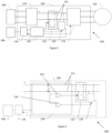
- a motor drive system 100 comprises a motor 102, motor drive electronics 104, a first energy source 106, and a second energy source 108.
- the motor 102 may be a motor for a vehicle (e.g. an aircraft) and may be configured to provide motion of the vehicle (e.g. the aircraft).
- the first energy source 106 is an AC voltage source (e.g. a three-phase AC voltage source) coupled to a rectifier 110.
- the rectifier 110 is coupled, via a DC link 112, to an inverter 114, and the inverter 114 is coupled to the motor 102.
- This arrangement allows electrical energy to be supplied to the motor 102 from the first energy source 106.
- the first energy source 106 and rectifier 110 may be replaced by a DC voltage source, such as a battery (e.g. in a hybrid car).
- the second energy source 108 is a DC voltage source, such as a battery (e.g. with a 28V input) coupled to an energy storage device 116.
- the energy storage device 116 is coupled to a controller 118. In this manner, electrical energy can be supplied to the controller 118 from one of the second energy source 108 or the energy storage device 116, as described below.
- the second energy source 108 may be at a higher or lower voltage than the first energy source 106.
- the rectifier 110, DC link 112, inverter 114, energy storage device 116, and controller 118 form part of the motor drive electronics 104, together with a DC/DC converter 120, and a (braking) resistor 122.
- the DC/DC converter 120 and (braking) resistor 122 are each coupled to the controller 118 and the DC link 112.
- the DC/DC converter is further coupled to the energy storage device 116.
- the DC link 112 is configured to transmit electrical energy to the motor 102, i.e. from the rectifier 110 to the inverter 114, while the DC/DC converter 120 is configured to reduce a voltage of the DC link 112.
- the controller 118 monitors the charge level of the energy storage device 116 and determines whether the charge level of the energy storage device 116 is above, at or below a predetermined storage threshold value (i.e. a standby voltage).
- the predetermined storage threshold value is a minimum charge level of the energy storage device 116 that is required to provide a desired hold-up time for the controller 118. In a motor drive system 100, the hold-up time is typically 10ms.
- the second energy source 108 charges the energy storage device 116 up to the predetermined storage threshold value and then maintains the charge level of the energy storage device 116 at the predetermined storage threshold value. This ensures that the energy storage device 116 can supply electrical energy to the controller 118 for a desired hold-up time if there is energy loss from the second energy source 108.
- the predetermined storage threshold value is not a maximum charge level of the energy storage device 116. Since the energy storage device 116 is maintained at the predetermined storage threshold value by the second energy source 108, the energy storage device 116 has reserve capacity to store energy generated during a braking (e.g. deceleration) operation and can therefore be charged above the predetermined storage threshold value (as described below).
- a braking e.g. deceleration
- the controller 118 comprises a first comparator circuit 126 and a second comparator circuit 124.
- the first comparator circuit 126 is coupled between the DC link 112 and the DC/DC converter 120, while the second comparator circuit 126 is coupled between the DC link 112 and the (braking) resistor 122.
- the controller 118 monitors the voltage of the DC link 112 using the comparator circuits 124, 126.
- the second comparator circuit 124 enables the (braking) resistor 122 to dissipate the excess regenerative energy. If the rate at which regenerative energy is generated exceeds the rate at which the energy storage device 116 can be charged, the DC link voltage may exceed the second predefined DC link threshold value.
- the second comparator circuit 124 enables the (braking) resistor 122 to dissipate the excess regenerative energy and bring the DC link voltage down towards the second predefined DC link threshold value while the DC/DC converter 120 transfers energy from the DC link 112 to the energy storage device 116.
- the second predefined DC link threshold value is greater than the first predefined DC link threshold value.
Landscapes
- Engineering & Computer Science (AREA)
- Power Engineering (AREA)
- Transportation (AREA)
- Mechanical Engineering (AREA)
- Chemical & Material Sciences (AREA)
- Combustion & Propulsion (AREA)
- Automation & Control Theory (AREA)
- Charge And Discharge Circuits For Batteries Or The Like (AREA)
- Electric Propulsion And Braking For Vehicles (AREA)
Priority Applications (2)
| Application Number | Priority Date | Filing Date | Title |
|---|---|---|---|
| EP23176345.9A EP4472058A1 (de) | 2023-05-31 | 2023-05-31 | Motorantriebssystem |
| US18/665,764 US20240400032A1 (en) | 2023-05-31 | 2024-05-16 | Motor drive system |
Applications Claiming Priority (1)
| Application Number | Priority Date | Filing Date | Title |
|---|---|---|---|
| EP23176345.9A EP4472058A1 (de) | 2023-05-31 | 2023-05-31 | Motorantriebssystem |
Publications (1)
| Publication Number | Publication Date |
|---|---|
| EP4472058A1 true EP4472058A1 (de) | 2024-12-04 |
Family
ID=86646682
Family Applications (1)
| Application Number | Title | Priority Date | Filing Date |
|---|---|---|---|
| EP23176345.9A Pending EP4472058A1 (de) | 2023-05-31 | 2023-05-31 | Motorantriebssystem |
Country Status (2)
| Country | Link |
|---|---|
| US (1) | US20240400032A1 (de) |
| EP (1) | EP4472058A1 (de) |
Citations (5)
| Publication number | Priority date | Publication date | Assignee | Title |
|---|---|---|---|---|
| US20040245951A1 (en) * | 2003-06-06 | 2004-12-09 | Fanuc Ltd. | Motor driving apparatus |
| EP2091055A2 (de) * | 2008-02-15 | 2009-08-19 | Honeywell International Inc. | Batterie, die Superkondensatorenergiespeicherladung ergänzt, und Entladungswandler |
| US20110100735A1 (en) * | 2009-11-05 | 2011-05-05 | Ise Corporation | Propulsion Energy Storage Control System and Method of Control |
| US20180264968A1 (en) * | 2015-11-18 | 2018-09-20 | Bayerische Motoren Werke Aktiengesellschaft | Multiple Storage System and Method for Operating a Multiple Storage System |
| CN105790422B (zh) * | 2016-04-13 | 2020-03-24 | 深圳市大疆创新科技有限公司 | 无人机断电续航方法、装置及系统 |
Family Cites Families (21)
| Publication number | Priority date | Publication date | Assignee | Title |
|---|---|---|---|---|
| JP3226599B2 (ja) * | 1992-05-19 | 2001-11-05 | 東芝アイティー・コントロールシステム株式会社 | バッテリーカーの制御方法及び装置 |
| JP3245334B2 (ja) * | 1995-08-03 | 2002-01-15 | 本田技研工業株式会社 | 電動車両の電源制御装置 |
| US7012392B2 (en) * | 2004-02-06 | 2006-03-14 | Honeywell International Inc. | Multi-stage dynamic braking resistor network |
| JP4021431B2 (ja) * | 2004-08-10 | 2007-12-12 | ファナック株式会社 | コンバータ装置、インバータ装置及びdcリンク電圧の制御方法 |
| US20060108867A1 (en) * | 2004-09-17 | 2006-05-25 | Mihai Ralea | Electromechanical braking system with electrical energy back-up and regenerative energy management |
| KR100837939B1 (ko) * | 2006-10-11 | 2008-06-13 | 현대자동차주식회사 | 하이브리드 연료전지 버스의 파워 시스템 및 그 제어 방법 |
| US8058830B2 (en) * | 2007-07-30 | 2011-11-15 | GM Global Technology Operations LLC | Charging energy sources with a rectifier using double-ended inverter system |
| JP5670398B2 (ja) * | 2012-09-10 | 2015-02-18 | ファナック株式会社 | 少なくとも2つの抵抗放電手段を有するモータ制御装置 |
| JP2015143039A (ja) * | 2014-01-31 | 2015-08-06 | トヨタ自動車株式会社 | 車両 |
| DE102015201541A1 (de) * | 2015-01-29 | 2016-08-04 | Ifm Electronic Gmbh | Versorgungsschaltung für eine programmierbare Steuereinheit in mobilen Arbeitsmaschinen |
| JP6428735B2 (ja) * | 2016-09-23 | 2018-11-28 | トヨタ自動車株式会社 | 電力変換装置 |
| JP6545230B2 (ja) * | 2017-08-31 | 2019-07-17 | 本田技研工業株式会社 | 車両の電源システム |
| JP6554151B2 (ja) * | 2017-08-31 | 2019-07-31 | 本田技研工業株式会社 | 車両の電源システム |
| CN112567622B (zh) * | 2018-06-12 | 2025-01-14 | 株式会社不二越 | 制动器电路放电系统 |
| JP6845843B2 (ja) * | 2018-12-14 | 2021-03-24 | 本田技研工業株式会社 | 車両の電源システム |
| JP7334096B2 (ja) * | 2019-09-06 | 2023-08-28 | 日立Astemo株式会社 | 電力制御装置 |
| JP6818835B1 (ja) * | 2019-10-02 | 2021-01-20 | 株式会社ケーヒン | 電力制御装置 |
| JP2021058058A (ja) * | 2019-10-02 | 2021-04-08 | 株式会社ケーヒン | 電力変換装置 |
| JP7424790B2 (ja) * | 2019-10-21 | 2024-01-30 | 本田技研工業株式会社 | 車両の電源システム |
| EP4020789B1 (de) * | 2020-12-23 | 2024-10-30 | Hamilton Sundstrand Corporation | Motorantriebssystem |
| EP4148971A1 (de) * | 2021-09-14 | 2023-03-15 | Hamilton Sundstrand Corporation | Steuerung der dissipation von regenerativer energie in einem mehrkanalantrieb |
-
2023
- 2023-05-31 EP EP23176345.9A patent/EP4472058A1/de active Pending
-
2024
- 2024-05-16 US US18/665,764 patent/US20240400032A1/en active Pending
Patent Citations (5)
| Publication number | Priority date | Publication date | Assignee | Title |
|---|---|---|---|---|
| US20040245951A1 (en) * | 2003-06-06 | 2004-12-09 | Fanuc Ltd. | Motor driving apparatus |
| EP2091055A2 (de) * | 2008-02-15 | 2009-08-19 | Honeywell International Inc. | Batterie, die Superkondensatorenergiespeicherladung ergänzt, und Entladungswandler |
| US20110100735A1 (en) * | 2009-11-05 | 2011-05-05 | Ise Corporation | Propulsion Energy Storage Control System and Method of Control |
| US20180264968A1 (en) * | 2015-11-18 | 2018-09-20 | Bayerische Motoren Werke Aktiengesellschaft | Multiple Storage System and Method for Operating a Multiple Storage System |
| CN105790422B (zh) * | 2016-04-13 | 2020-03-24 | 深圳市大疆创新科技有限公司 | 无人机断电续航方法、装置及系统 |
Also Published As
| Publication number | Publication date |
|---|---|
| US20240400032A1 (en) | 2024-12-05 |
Similar Documents
| Publication | Publication Date | Title |
|---|---|---|
| US8120290B2 (en) | Energy management system to improve efficiency of electric and hybrid drive trains | |
| EP2573033B1 (de) | Verwaltung von Leistung aus mehreren Quellen in einem Hebeleistungssystem | |
| JP4252953B2 (ja) | 電力貯蔵式き電線電圧補償装置及び方法 | |
| EP2326587B1 (de) | Leitungsstrom- und energiespeicherungssteuerung für einen aufzugsantrieb | |
| EP2994973A1 (de) | Hybridenergiebatterie oder superkondensatorgespeiste antriebstopologien | |
| CN103314504A (zh) | 车辆用电源系统 | |
| JP6488856B2 (ja) | 蓄電装置を備えた駆動制御装置 | |
| JP4238190B2 (ja) | 電力貯蔵式回生電力吸収装置およびその制御方法 | |
| JP2000201492A (ja) | 電動機の駆動方法及び装置 | |
| CN110149000A (zh) | 车载取力行车发电系统防掉电补偿系统 | |
| EP4472058A1 (de) | Motorantriebssystem | |
| EP2492132B1 (de) | Antriebsvorrichtung für ein Eisenbahnfahrzeug | |
| WO2012137315A1 (ja) | 車両用電源システム | |
| Joshi et al. | Modified ultracapacitor voltage control loop for battery/UC HESS | |
| US11552583B2 (en) | Drive system | |
| US10205321B2 (en) | Electrical accumulators for multilevel power systems | |
| CN115848167A (zh) | 工程车辆的控制方法、装置、可读存储介质和工程车辆 | |
| EP4336724A1 (de) | Motorantriebssystem und drehmomentverteilungsverfahren dafür | |
| EP4238806B1 (de) | Antriebsvorrichtung für eine elektrische maschine eines schwerlastfahrzeugs | |
| WO2010019123A1 (en) | Management of power from multiple sources in an elevator power system | |
| HK1159590B (en) | Management of power from multiple sources in an elevator power system | |
| WO2019201426A1 (en) | Drive unit, robot and method | |
| HK1159592B (en) | Line current and energy storage control for an elevator drive | |
| HK1189198A1 (zh) | 蓄电装置及其设置和运用方法 |
Legal Events
| Date | Code | Title | Description |
|---|---|---|---|
| PUAI | Public reference made under article 153(3) epc to a published international application that has entered the european phase |
Free format text: ORIGINAL CODE: 0009012 |
|
| STAA | Information on the status of an ep patent application or granted ep patent |
Free format text: STATUS: THE APPLICATION HAS BEEN PUBLISHED |
|
| AK | Designated contracting states |
Kind code of ref document: A1 Designated state(s): AL AT BE BG CH CY CZ DE DK EE ES FI FR GB GR HR HU IE IS IT LI LT LU LV MC ME MK MT NL NO PL PT RO RS SE SI SK SM TR |
|
| STAA | Information on the status of an ep patent application or granted ep patent |
Free format text: STATUS: REQUEST FOR EXAMINATION WAS MADE |
|
| 17P | Request for examination filed |
Effective date: 20250603 |