EP4470746A1 - Strömungswegformungsvorrichtung und extrusionsformungsvorrichtung - Google Patents
Strömungswegformungsvorrichtung und extrusionsformungsvorrichtung Download PDFInfo
- Publication number
- EP4470746A1 EP4470746A1 EP24175722.8A EP24175722A EP4470746A1 EP 4470746 A1 EP4470746 A1 EP 4470746A1 EP 24175722 A EP24175722 A EP 24175722A EP 4470746 A1 EP4470746 A1 EP 4470746A1
- Authority
- EP
- European Patent Office
- Prior art keywords
- flow path
- path forming
- forming surface
- droplet
- plastic composition
- Prior art date
- Legal status (The legal status is an assumption and is not a legal conclusion. Google has not performed a legal analysis and makes no representation as to the accuracy of the status listed.)
- Pending
Links
- 238000001125 extrusion Methods 0.000 title claims description 40
- 239000002985 plastic film Substances 0.000 title claims description 12
- 239000000203 mixture Substances 0.000 claims abstract description 101
- 229920003023 plastic Polymers 0.000 claims abstract description 92
- 239000004033 plastic Substances 0.000 claims abstract description 92
- XLYOFNOQVPJJNP-UHFFFAOYSA-N water Substances O XLYOFNOQVPJJNP-UHFFFAOYSA-N 0.000 claims abstract description 32
- 230000008021 deposition Effects 0.000 claims abstract description 23
- 229920000747 poly(lactic acid) Polymers 0.000 claims description 43
- 239000004626 polylactic acid Substances 0.000 claims description 41
- 238000002844 melting Methods 0.000 claims description 34
- 230000008018 melting Effects 0.000 claims description 34
- 229920006167 biodegradable resin Polymers 0.000 claims description 13
- 238000004519 manufacturing process Methods 0.000 claims description 12
- 238000011144 upstream manufacturing Methods 0.000 claims description 8
- 239000012530 fluid Substances 0.000 description 67
- 238000004898 kneading Methods 0.000 description 64
- 238000000034 method Methods 0.000 description 59
- 239000000047 product Substances 0.000 description 55
- 229920003232 aliphatic polyester Polymers 0.000 description 51
- 239000004645 polyester resin Substances 0.000 description 49
- CURLTUGMZLYLDI-UHFFFAOYSA-N Carbon dioxide Chemical compound O=C=O CURLTUGMZLYLDI-UHFFFAOYSA-N 0.000 description 42
- 229920005989 resin Polymers 0.000 description 33
- 239000011347 resin Substances 0.000 description 33
- 238000005187 foaming Methods 0.000 description 32
- 238000005259 measurement Methods 0.000 description 26
- 239000000945 filler Substances 0.000 description 25
- 239000004088 foaming agent Substances 0.000 description 24
- 238000011282 treatment Methods 0.000 description 23
- 239000000463 material Substances 0.000 description 22
- 239000001569 carbon dioxide Substances 0.000 description 21
- 229910002092 carbon dioxide Inorganic materials 0.000 description 21
- 239000003431 cross linking reagent Substances 0.000 description 21
- 239000002994 raw material Substances 0.000 description 19
- 239000006260 foam Substances 0.000 description 18
- 238000000151 deposition Methods 0.000 description 17
- 239000000088 plastic resin Substances 0.000 description 17
- 238000000465 moulding Methods 0.000 description 16
- 239000002667 nucleating agent Substances 0.000 description 16
- 238000012545 processing Methods 0.000 description 16
- 238000000576 coating method Methods 0.000 description 15
- 239000004594 Masterbatch (MB) Substances 0.000 description 14
- 230000000052 comparative effect Effects 0.000 description 14
- 230000007547 defect Effects 0.000 description 14
- 230000003746 surface roughness Effects 0.000 description 14
- 238000002156 mixing Methods 0.000 description 12
- 239000000126 substance Substances 0.000 description 12
- 238000002474 experimental method Methods 0.000 description 11
- 239000007789 gas Substances 0.000 description 11
- 238000012795 verification Methods 0.000 description 11
- 239000011342 resin composition Substances 0.000 description 10
- 239000000654 additive Substances 0.000 description 9
- 239000011248 coating agent Substances 0.000 description 9
- 238000010438 heat treatment Methods 0.000 description 9
- 230000008569 process Effects 0.000 description 9
- 239000002904 solvent Substances 0.000 description 9
- IJGRMHOSHXDMSA-UHFFFAOYSA-N Atomic nitrogen Chemical compound N#N IJGRMHOSHXDMSA-UHFFFAOYSA-N 0.000 description 8
- -1 cemented carbide Inorganic materials 0.000 description 8
- 238000002791 soaking Methods 0.000 description 8
- 238000011156 evaluation Methods 0.000 description 7
- 239000007788 liquid Substances 0.000 description 7
- 238000012360 testing method Methods 0.000 description 7
- VYPSYNLAJGMNEJ-UHFFFAOYSA-N Silicium dioxide Chemical compound O=[Si]=O VYPSYNLAJGMNEJ-UHFFFAOYSA-N 0.000 description 6
- PPBRXRYQALVLMV-UHFFFAOYSA-N Styrene Chemical compound C=CC1=CC=CC=C1 PPBRXRYQALVLMV-UHFFFAOYSA-N 0.000 description 6
- 230000032683 aging Effects 0.000 description 6
- VLKZOEOYAKHREP-UHFFFAOYSA-N n-Hexane Chemical compound CCCCCC VLKZOEOYAKHREP-UHFFFAOYSA-N 0.000 description 6
- 150000002894 organic compounds Chemical class 0.000 description 6
- 238000005488 sandblasting Methods 0.000 description 6
- PXHVJJICTQNCMI-UHFFFAOYSA-N Nickel Chemical compound [Ni] PXHVJJICTQNCMI-UHFFFAOYSA-N 0.000 description 5
- 239000011162 core material Substances 0.000 description 5
- 238000012937 correction Methods 0.000 description 5
- 230000006866 deterioration Effects 0.000 description 5
- 229910052751 metal Inorganic materials 0.000 description 5
- 239000002184 metal Substances 0.000 description 5
- 238000010422 painting Methods 0.000 description 5
- 238000007747 plating Methods 0.000 description 5
- UQDJGEHQDNVPGU-UHFFFAOYSA-N serine phosphoethanolamine Chemical compound [NH3+]CCOP([O-])(=O)OCC([NH3+])C([O-])=O UQDJGEHQDNVPGU-UHFFFAOYSA-N 0.000 description 5
- LCGLNKUTAGEVQW-UHFFFAOYSA-N Dimethyl ether Chemical compound COC LCGLNKUTAGEVQW-UHFFFAOYSA-N 0.000 description 4
- JVTAAEKCZFNVCJ-REOHCLBHSA-N L-lactic acid Chemical compound C[C@H](O)C(O)=O JVTAAEKCZFNVCJ-REOHCLBHSA-N 0.000 description 4
- ATUOYWHBWRKTHZ-UHFFFAOYSA-N Propane Chemical compound CCC ATUOYWHBWRKTHZ-UHFFFAOYSA-N 0.000 description 4
- 238000004458 analytical method Methods 0.000 description 4
- 238000006243 chemical reaction Methods 0.000 description 4
- 229920001577 copolymer Polymers 0.000 description 4
- 238000010586 diagram Methods 0.000 description 4
- 230000007613 environmental effect Effects 0.000 description 4
- 238000002290 gas chromatography-mass spectrometry Methods 0.000 description 4
- 238000002347 injection Methods 0.000 description 4
- 239000007924 injection Substances 0.000 description 4
- JVTAAEKCZFNVCJ-UHFFFAOYSA-N lactic acid Chemical compound CC(O)C(O)=O JVTAAEKCZFNVCJ-UHFFFAOYSA-N 0.000 description 4
- 238000000691 measurement method Methods 0.000 description 4
- 229910052757 nitrogen Inorganic materials 0.000 description 4
- 102200082816 rs34868397 Human genes 0.000 description 4
- VYZAMTAEIAYCRO-UHFFFAOYSA-N Chromium Chemical compound [Cr] VYZAMTAEIAYCRO-UHFFFAOYSA-N 0.000 description 3
- KFZMGEQAYNKOFK-UHFFFAOYSA-N Isopropanol Chemical compound CC(C)O KFZMGEQAYNKOFK-UHFFFAOYSA-N 0.000 description 3
- YXFVVABEGXRONW-UHFFFAOYSA-N Toluene Chemical compound CC1=CC=CC=C1 YXFVVABEGXRONW-UHFFFAOYSA-N 0.000 description 3
- PNEYBMLMFCGWSK-UHFFFAOYSA-N aluminium oxide Inorganic materials [O-2].[O-2].[O-2].[Al+3].[Al+3] PNEYBMLMFCGWSK-UHFFFAOYSA-N 0.000 description 3
- 239000003963 antioxidant agent Substances 0.000 description 3
- 230000015572 biosynthetic process Effects 0.000 description 3
- 238000009835 boiling Methods 0.000 description 3
- 230000008859 change Effects 0.000 description 3
- 239000002131 composite material Substances 0.000 description 3
- 150000001875 compounds Chemical class 0.000 description 3
- 230000007423 decrease Effects 0.000 description 3
- 238000013461 design Methods 0.000 description 3
- 238000001514 detection method Methods 0.000 description 3
- 235000013305 food Nutrition 0.000 description 3
- 229910003475 inorganic filler Inorganic materials 0.000 description 3
- 239000011256 inorganic filler Substances 0.000 description 3
- 239000000314 lubricant Substances 0.000 description 3
- VNWKTOKETHGBQD-UHFFFAOYSA-N methane Chemical compound C VNWKTOKETHGBQD-UHFFFAOYSA-N 0.000 description 3
- 229910052759 nickel Inorganic materials 0.000 description 3
- 239000012766 organic filler Substances 0.000 description 3
- 239000004014 plasticizer Substances 0.000 description 3
- 229920000070 poly-3-hydroxybutyrate Polymers 0.000 description 3
- 229920001296 polysiloxane Polymers 0.000 description 3
- 239000000377 silicon dioxide Substances 0.000 description 3
- 238000003878 thermal aging Methods 0.000 description 3
- 239000003017 thermal stabilizer Substances 0.000 description 3
- 238000005303 weighing Methods 0.000 description 3
- ZFFMLCVRJBZUDZ-UHFFFAOYSA-N 2,3-dimethylbutane Chemical compound CC(C)C(C)C ZFFMLCVRJBZUDZ-UHFFFAOYSA-N 0.000 description 2
- REKYPYSUBKSCAT-UHFFFAOYSA-N 3-hydroxypentanoic acid Chemical compound CCC(O)CC(O)=O REKYPYSUBKSCAT-UHFFFAOYSA-N 0.000 description 2
- VTYYLEPIZMXCLO-UHFFFAOYSA-L Calcium carbonate Chemical compound [Ca+2].[O-]C([O-])=O VTYYLEPIZMXCLO-UHFFFAOYSA-L 0.000 description 2
- 229930182843 D-Lactic acid Natural products 0.000 description 2
- JVTAAEKCZFNVCJ-UWTATZPHSA-N D-lactic acid Chemical compound C[C@@H](O)C(O)=O JVTAAEKCZFNVCJ-UWTATZPHSA-N 0.000 description 2
- 239000004593 Epoxy Substances 0.000 description 2
- LFQSCWFLJHTTHZ-UHFFFAOYSA-N Ethanol Chemical compound CCO LFQSCWFLJHTTHZ-UHFFFAOYSA-N 0.000 description 2
- YCKRFDGAMUMZLT-UHFFFAOYSA-N Fluorine atom Chemical compound [F] YCKRFDGAMUMZLT-UHFFFAOYSA-N 0.000 description 2
- 238000005481 NMR spectroscopy Methods 0.000 description 2
- GQPLMRYTRLFLPF-UHFFFAOYSA-N Nitrous Oxide Chemical compound [O-][N+]#N GQPLMRYTRLFLPF-UHFFFAOYSA-N 0.000 description 2
- OFBQJSOFQDEBGM-UHFFFAOYSA-N Pentane Chemical compound CCCCC OFBQJSOFQDEBGM-UHFFFAOYSA-N 0.000 description 2
- 239000004793 Polystyrene Substances 0.000 description 2
- 229910000831 Steel Inorganic materials 0.000 description 2
- XLOMVQKBTHCTTD-UHFFFAOYSA-N Zinc monoxide Chemical compound [Zn]=O XLOMVQKBTHCTTD-UHFFFAOYSA-N 0.000 description 2
- MCMNRKCIXSYSNV-UHFFFAOYSA-N Zirconium dioxide Chemical compound O=[Zr]=O MCMNRKCIXSYSNV-UHFFFAOYSA-N 0.000 description 2
- ADCOVFLJGNWWNZ-UHFFFAOYSA-N antimony trioxide Chemical compound O=[Sb]O[Sb]=O ADCOVFLJGNWWNZ-UHFFFAOYSA-N 0.000 description 2
- 230000003078 antioxidant effect Effects 0.000 description 2
- WPYMKLBDIGXBTP-UHFFFAOYSA-N benzoic acid Chemical compound OC(=O)C1=CC=CC=C1 WPYMKLBDIGXBTP-UHFFFAOYSA-N 0.000 description 2
- 229920000704 biodegradable plastic Polymers 0.000 description 2
- 238000011088 calibration curve Methods 0.000 description 2
- 239000001913 cellulose Substances 0.000 description 2
- 229920002678 cellulose Polymers 0.000 description 2
- 238000005229 chemical vapour deposition Methods 0.000 description 2
- NEHMKBQYUWJMIP-UHFFFAOYSA-N chloromethane Chemical compound ClC NEHMKBQYUWJMIP-UHFFFAOYSA-N 0.000 description 2
- 230000001276 controlling effect Effects 0.000 description 2
- 238000004132 cross linking Methods 0.000 description 2
- 229940022769 d- lactic acid Drugs 0.000 description 2
- 230000000694 effects Effects 0.000 description 2
- 238000010304 firing Methods 0.000 description 2
- 239000011737 fluorine Substances 0.000 description 2
- 229910052731 fluorine Inorganic materials 0.000 description 2
- 238000004817 gas chromatography Methods 0.000 description 2
- 239000011521 glass Substances 0.000 description 2
- 229920001519 homopolymer Polymers 0.000 description 2
- NNPPMTNAJDCUHE-UHFFFAOYSA-N isobutane Chemical compound CC(C)C NNPPMTNAJDCUHE-UHFFFAOYSA-N 0.000 description 2
- QWTDNUCVQCZILF-UHFFFAOYSA-N isopentane Chemical compound CCC(C)C QWTDNUCVQCZILF-UHFFFAOYSA-N 0.000 description 2
- 239000004310 lactic acid Substances 0.000 description 2
- 235000014655 lactic acid Nutrition 0.000 description 2
- JJTUDXZGHPGLLC-UHFFFAOYSA-N lactide Chemical compound CC1OC(=O)C(C)OC1=O JJTUDXZGHPGLLC-UHFFFAOYSA-N 0.000 description 2
- 239000000155 melt Substances 0.000 description 2
- 239000008188 pellet Substances 0.000 description 2
- 238000005240 physical vapour deposition Methods 0.000 description 2
- 229920000642 polymer Polymers 0.000 description 2
- 238000006116 polymerization reaction Methods 0.000 description 2
- 229920002223 polystyrene Polymers 0.000 description 2
- 239000001294 propane Substances 0.000 description 2
- IJDNQMDRQITEOD-UHFFFAOYSA-N sec-butylidene Natural products CCCC IJDNQMDRQITEOD-UHFFFAOYSA-N 0.000 description 2
- 229910052604 silicate mineral Inorganic materials 0.000 description 2
- 238000001228 spectrum Methods 0.000 description 2
- 239000010959 steel Substances 0.000 description 2
- 238000010408 sweeping Methods 0.000 description 2
- 229920005992 thermoplastic resin Polymers 0.000 description 2
- ZMKVBUOZONDYBW-UHFFFAOYSA-N 1,6-dioxecane-2,5-dione Chemical compound O=C1CCC(=O)OCCCCO1 ZMKVBUOZONDYBW-UHFFFAOYSA-N 0.000 description 1
- JQXYBDVZAUEPDL-UHFFFAOYSA-N 2-methylidene-5-phenylpent-4-enoic acid Chemical compound OC(=O)C(=C)CC=CC1=CC=CC=C1 JQXYBDVZAUEPDL-UHFFFAOYSA-N 0.000 description 1
- PYSRRFNXTXNWCD-UHFFFAOYSA-N 3-(2-phenylethenyl)furan-2,5-dione Chemical compound O=C1OC(=O)C(C=CC=2C=CC=CC=2)=C1 PYSRRFNXTXNWCD-UHFFFAOYSA-N 0.000 description 1
- JJTUDXZGHPGLLC-IMJSIDKUSA-N 4511-42-6 Chemical compound C[C@@H]1OC(=O)[C@H](C)OC1=O JJTUDXZGHPGLLC-IMJSIDKUSA-N 0.000 description 1
- RSWGJHLUYNHPMX-UHFFFAOYSA-N Abietic-Saeure Chemical class C12CCC(C(C)C)=CC2=CCC2C1(C)CCCC2(C)C(O)=O RSWGJHLUYNHPMX-UHFFFAOYSA-N 0.000 description 1
- 239000005995 Aluminium silicate Substances 0.000 description 1
- 241000239290 Araneae Species 0.000 description 1
- 229910052582 BN Inorganic materials 0.000 description 1
- 239000005711 Benzoic acid Substances 0.000 description 1
- PZNSFCLAULLKQX-UHFFFAOYSA-N Boron nitride Chemical compound N#B PZNSFCLAULLKQX-UHFFFAOYSA-N 0.000 description 1
- OKTJSMMVPCPJKN-UHFFFAOYSA-N Carbon Chemical compound [C] OKTJSMMVPCPJKN-UHFFFAOYSA-N 0.000 description 1
- 229920000049 Carbon (fiber) Polymers 0.000 description 1
- UGFAIRIUMAVXCW-UHFFFAOYSA-N Carbon monoxide Chemical compound [O+]#[C-] UGFAIRIUMAVXCW-UHFFFAOYSA-N 0.000 description 1
- 229910000975 Carbon steel Inorganic materials 0.000 description 1
- 229910000669 Chrome steel Inorganic materials 0.000 description 1
- FBPFZTCFMRRESA-JGWLITMVSA-N D-glucitol Chemical class OC[C@H](O)[C@@H](O)[C@H](O)[C@H](O)CO FBPFZTCFMRRESA-JGWLITMVSA-N 0.000 description 1
- OTMSDBZUPAUEDD-UHFFFAOYSA-N Ethane Chemical compound CC OTMSDBZUPAUEDD-UHFFFAOYSA-N 0.000 description 1
- VGGSQFUCUMXWEO-UHFFFAOYSA-N Ethene Chemical compound C=C VGGSQFUCUMXWEO-UHFFFAOYSA-N 0.000 description 1
- 239000005977 Ethylene Substances 0.000 description 1
- 239000004812 Fluorinated ethylene propylene Substances 0.000 description 1
- 208000033962 Fontaine progeroid syndrome Diseases 0.000 description 1
- 229910000760 Hardened steel Inorganic materials 0.000 description 1
- 229910000997 High-speed steel Inorganic materials 0.000 description 1
- UFHFLCQGNIYNRP-UHFFFAOYSA-N Hydrogen Chemical compound [H][H] UFHFLCQGNIYNRP-UHFFFAOYSA-N 0.000 description 1
- 229910000503 Na-aluminosilicate Inorganic materials 0.000 description 1
- 229910018104 Ni-P Inorganic materials 0.000 description 1
- 229910018487 Ni—Cr Inorganic materials 0.000 description 1
- 229910018536 Ni—P Inorganic materials 0.000 description 1
- MXRIRQGCELJRSN-UHFFFAOYSA-N O.O.O.[Al] Chemical compound O.O.O.[Al] MXRIRQGCELJRSN-UHFFFAOYSA-N 0.000 description 1
- 240000007594 Oryza sativa Species 0.000 description 1
- 235000007164 Oryza sativa Nutrition 0.000 description 1
- CBENFWSGALASAD-UHFFFAOYSA-N Ozone Chemical compound [O-][O+]=O CBENFWSGALASAD-UHFFFAOYSA-N 0.000 description 1
- 229910019142 PO4 Inorganic materials 0.000 description 1
- 239000002033 PVDF binder Substances 0.000 description 1
- 239000004813 Perfluoroalkoxy alkane Substances 0.000 description 1
- 229920000954 Polyglycolide Polymers 0.000 description 1
- 239000004721 Polyphenylene oxide Substances 0.000 description 1
- KHPCPRHQVVSZAH-HUOMCSJISA-N Rosin Chemical class O(C/C=C/c1ccccc1)[C@H]1[C@H](O)[C@@H](O)[C@@H](O)[C@@H](CO)O1 KHPCPRHQVVSZAH-HUOMCSJISA-N 0.000 description 1
- BLRPTPMANUNPDV-UHFFFAOYSA-N Silane Chemical compound [SiH4] BLRPTPMANUNPDV-UHFFFAOYSA-N 0.000 description 1
- 229920002472 Starch Polymers 0.000 description 1
- 229920000147 Styrene maleic anhydride Polymers 0.000 description 1
- 229910034327 TiC Inorganic materials 0.000 description 1
- ATJFFYVFTNAWJD-UHFFFAOYSA-N Tin Chemical compound [Sn] ATJFFYVFTNAWJD-UHFFFAOYSA-N 0.000 description 1
- 229910021536 Zeolite Inorganic materials 0.000 description 1
- FMRLDPWIRHBCCC-UHFFFAOYSA-L Zinc carbonate Chemical compound [Zn+2].[O-]C([O-])=O FMRLDPWIRHBCCC-UHFFFAOYSA-L 0.000 description 1
- 239000002253 acid Substances 0.000 description 1
- 230000000996 additive effect Effects 0.000 description 1
- WNLRTRBMVRJNCN-UHFFFAOYSA-L adipate(2-) Chemical compound [O-]C(=O)CCCCC([O-])=O WNLRTRBMVRJNCN-UHFFFAOYSA-L 0.000 description 1
- 150000001335 aliphatic alkanes Chemical class 0.000 description 1
- 229910045601 alloy Inorganic materials 0.000 description 1
- 239000000956 alloy Substances 0.000 description 1
- 229910052782 aluminium Inorganic materials 0.000 description 1
- XAGFODPZIPBFFR-UHFFFAOYSA-N aluminium Chemical compound [Al] XAGFODPZIPBFFR-UHFFFAOYSA-N 0.000 description 1
- 235000012211 aluminium silicate Nutrition 0.000 description 1
- ANBBXQWFNXMHLD-UHFFFAOYSA-N aluminum;sodium;oxygen(2-) Chemical compound [O-2].[O-2].[Na+].[Al+3] ANBBXQWFNXMHLD-UHFFFAOYSA-N 0.000 description 1
- 238000010923 batch production Methods 0.000 description 1
- 235000010233 benzoic acid Nutrition 0.000 description 1
- 238000005422 blasting Methods 0.000 description 1
- 238000007664 blowing Methods 0.000 description 1
- 230000009172 bursting Effects 0.000 description 1
- 239000001273 butane Substances 0.000 description 1
- 229910000019 calcium carbonate Inorganic materials 0.000 description 1
- 239000000378 calcium silicate Substances 0.000 description 1
- 229910052918 calcium silicate Inorganic materials 0.000 description 1
- OYACROKNLOSFPA-UHFFFAOYSA-N calcium;dioxido(oxo)silane Chemical compound [Ca+2].[O-][Si]([O-])=O OYACROKNLOSFPA-UHFFFAOYSA-N 0.000 description 1
- XFWJKVMFIVXPKK-UHFFFAOYSA-N calcium;oxido(oxo)alumane Chemical compound [Ca+2].[O-][Al]=O.[O-][Al]=O XFWJKVMFIVXPKK-UHFFFAOYSA-N 0.000 description 1
- 239000006229 carbon black Substances 0.000 description 1
- 239000004917 carbon fiber Substances 0.000 description 1
- 229910002091 carbon monoxide Inorganic materials 0.000 description 1
- 239000010962 carbon steel Substances 0.000 description 1
- 239000012159 carrier gas Substances 0.000 description 1
- 239000000919 ceramic Substances 0.000 description 1
- 238000003486 chemical etching Methods 0.000 description 1
- HRYZWHHZPQKTII-UHFFFAOYSA-N chloroethane Chemical compound CCCl HRYZWHHZPQKTII-UHFFFAOYSA-N 0.000 description 1
- 229910052804 chromium Inorganic materials 0.000 description 1
- 239000011651 chromium Substances 0.000 description 1
- VNNRSPGTAMTISX-UHFFFAOYSA-N chromium nickel Chemical compound [Cr].[Ni] VNNRSPGTAMTISX-UHFFFAOYSA-N 0.000 description 1
- 238000004140 cleaning Methods 0.000 description 1
- 238000004581 coalescence Methods 0.000 description 1
- 239000011247 coating layer Substances 0.000 description 1
- 239000013065 commercial product Substances 0.000 description 1
- 238000010924 continuous production Methods 0.000 description 1
- 230000008878 coupling Effects 0.000 description 1
- 238000010168 coupling process Methods 0.000 description 1
- 238000005859 coupling reaction Methods 0.000 description 1
- 239000013078 crystal Substances 0.000 description 1
- 238000002425 crystallisation Methods 0.000 description 1
- 230000008025 crystallization Effects 0.000 description 1
- 238000005520 cutting process Methods 0.000 description 1
- 230000003247 decreasing effect Effects 0.000 description 1
- 238000005238 degreasing Methods 0.000 description 1
- 230000001066 destructive effect Effects 0.000 description 1
- GDVKFRBCXAPAQJ-UHFFFAOYSA-A dialuminum;hexamagnesium;carbonate;hexadecahydroxide Chemical compound [OH-].[OH-].[OH-].[OH-].[OH-].[OH-].[OH-].[OH-].[OH-].[OH-].[OH-].[OH-].[OH-].[OH-].[OH-].[OH-].[Mg+2].[Mg+2].[Mg+2].[Mg+2].[Mg+2].[Mg+2].[Al+3].[Al+3].[O-]C([O-])=O GDVKFRBCXAPAQJ-UHFFFAOYSA-A 0.000 description 1
- 238000010790 dilution Methods 0.000 description 1
- 239000012895 dilution Substances 0.000 description 1
- AFABGHUZZDYHJO-UHFFFAOYSA-N dimethyl butane Natural products CCCC(C)C AFABGHUZZDYHJO-UHFFFAOYSA-N 0.000 description 1
- HNPSIPDUKPIQMN-UHFFFAOYSA-N dioxosilane;oxo(oxoalumanyloxy)alumane Chemical compound O=[Si]=O.O=[Al]O[Al]=O HNPSIPDUKPIQMN-UHFFFAOYSA-N 0.000 description 1
- NJLLQSBAHIKGKF-UHFFFAOYSA-N dipotassium dioxido(oxo)titanium Chemical compound [K+].[K+].[O-][Ti]([O-])=O NJLLQSBAHIKGKF-UHFFFAOYSA-N 0.000 description 1
- 238000009826 distribution Methods 0.000 description 1
- 238000001035 drying Methods 0.000 description 1
- 238000004043 dyeing Methods 0.000 description 1
- 238000009760 electrical discharge machining Methods 0.000 description 1
- 238000005868 electrolysis reaction Methods 0.000 description 1
- 238000005530 etching Methods 0.000 description 1
- 150000002170 ethers Chemical class 0.000 description 1
- 229960003750 ethyl chloride Drugs 0.000 description 1
- 229920000840 ethylene tetrafluoroethylene copolymer Polymers 0.000 description 1
- 239000004744 fabric Substances 0.000 description 1
- 239000000835 fiber Substances 0.000 description 1
- 235000013312 flour Nutrition 0.000 description 1
- 239000003365 glass fiber Substances 0.000 description 1
- 239000010439 graphite Substances 0.000 description 1
- 229910002804 graphite Inorganic materials 0.000 description 1
- 230000005484 gravity Effects 0.000 description 1
- 150000008282 halocarbons Chemical class 0.000 description 1
- 239000010903 husk Substances 0.000 description 1
- 229930195733 hydrocarbon Natural products 0.000 description 1
- 150000002430 hydrocarbons Chemical class 0.000 description 1
- 239000001257 hydrogen Substances 0.000 description 1
- 229910052739 hydrogen Inorganic materials 0.000 description 1
- 229910001701 hydrotalcite Inorganic materials 0.000 description 1
- 229960001545 hydrotalcite Drugs 0.000 description 1
- 230000006872 improvement Effects 0.000 description 1
- 238000000752 ionisation method Methods 0.000 description 1
- 239000001282 iso-butane Substances 0.000 description 1
- 239000012948 isocyanate Substances 0.000 description 1
- NLYAJNPCOHFWQQ-UHFFFAOYSA-N kaolin Chemical compound O.O.O=[Al]O[Si](=O)O[Si](=O)O[Al]=O NLYAJNPCOHFWQQ-UHFFFAOYSA-N 0.000 description 1
- 239000010410 layer Substances 0.000 description 1
- 238000003754 machining Methods 0.000 description 1
- 239000001095 magnesium carbonate Substances 0.000 description 1
- ZLNQQNXFFQJAID-UHFFFAOYSA-L magnesium carbonate Chemical compound [Mg+2].[O-]C([O-])=O ZLNQQNXFFQJAID-UHFFFAOYSA-L 0.000 description 1
- 229910000021 magnesium carbonate Inorganic materials 0.000 description 1
- 235000014380 magnesium carbonate Nutrition 0.000 description 1
- HCWCAKKEBCNQJP-UHFFFAOYSA-N magnesium orthosilicate Chemical compound [Mg+2].[Mg+2].[O-][Si]([O-])([O-])[O-] HCWCAKKEBCNQJP-UHFFFAOYSA-N 0.000 description 1
- 239000000395 magnesium oxide Substances 0.000 description 1
- CPLXHLVBOLITMK-UHFFFAOYSA-N magnesium oxide Inorganic materials [Mg]=O CPLXHLVBOLITMK-UHFFFAOYSA-N 0.000 description 1
- 239000000391 magnesium silicate Substances 0.000 description 1
- 229910052919 magnesium silicate Inorganic materials 0.000 description 1
- 235000019792 magnesium silicate Nutrition 0.000 description 1
- AXZKOIWUVFPNLO-UHFFFAOYSA-N magnesium;oxygen(2-) Chemical compound [O-2].[Mg+2] AXZKOIWUVFPNLO-UHFFFAOYSA-N 0.000 description 1
- 238000012423 maintenance Methods 0.000 description 1
- 238000001819 mass spectrum Methods 0.000 description 1
- 150000002739 metals Chemical class 0.000 description 1
- 229920003145 methacrylic acid copolymer Polymers 0.000 description 1
- 229940117841 methacrylic acid copolymer Drugs 0.000 description 1
- 229940050176 methyl chloride Drugs 0.000 description 1
- 150000004767 nitrides Chemical class 0.000 description 1
- 229960001730 nitrous oxide Drugs 0.000 description 1
- 235000013842 nitrous oxide Nutrition 0.000 description 1
- 235000019645 odor Nutrition 0.000 description 1
- 230000009965 odorless effect Effects 0.000 description 1
- 230000003287 optical effect Effects 0.000 description 1
- 239000003960 organic solvent Substances 0.000 description 1
- 238000004806 packaging method and process Methods 0.000 description 1
- 239000002245 particle Substances 0.000 description 1
- 229920009441 perflouroethylene propylene Polymers 0.000 description 1
- 229920011301 perfluoro alkoxyl alkane Polymers 0.000 description 1
- 238000005191 phase separation Methods 0.000 description 1
- 239000010452 phosphate Substances 0.000 description 1
- 230000000704 physical effect Effects 0.000 description 1
- 238000009832 plasma treatment Methods 0.000 description 1
- 238000005498 polishing Methods 0.000 description 1
- 229920000314 poly p-methyl styrene Polymers 0.000 description 1
- 229920002493 poly(chlorotrifluoroethylene) Polymers 0.000 description 1
- 229920002285 poly(styrene-co-acrylonitrile) Polymers 0.000 description 1
- 229920002961 polybutylene succinate Polymers 0.000 description 1
- 239000004631 polybutylene succinate Substances 0.000 description 1
- 229920001610 polycaprolactone Polymers 0.000 description 1
- 239000004632 polycaprolactone Substances 0.000 description 1
- 239000005023 polychlorotrifluoroethylene (PCTFE) polymer Substances 0.000 description 1
- 239000004633 polyglycolic acid Substances 0.000 description 1
- 239000002861 polymer material Substances 0.000 description 1
- 229920006380 polyphenylene oxide Polymers 0.000 description 1
- 229920005990 polystyrene resin Polymers 0.000 description 1
- 239000004810 polytetrafluoroethylene Substances 0.000 description 1
- 229920001343 polytetrafluoroethylene Polymers 0.000 description 1
- 229920002981 polyvinylidene fluoride Polymers 0.000 description 1
- 230000002028 premature Effects 0.000 description 1
- 238000004064 recycling Methods 0.000 description 1
- 230000001105 regulatory effect Effects 0.000 description 1
- 239000005871 repellent Substances 0.000 description 1
- 230000002940 repellent Effects 0.000 description 1
- 238000011160 research Methods 0.000 description 1
- 230000004044 response Effects 0.000 description 1
- 235000009566 rice Nutrition 0.000 description 1
- 238000005096 rolling process Methods 0.000 description 1
- 238000004439 roughness measurement Methods 0.000 description 1
- 102220005308 rs33960931 Human genes 0.000 description 1
- 102220259718 rs34120878 Human genes 0.000 description 1
- 150000003839 salts Chemical class 0.000 description 1
- 230000035945 sensitivity Effects 0.000 description 1
- 238000000926 separation method Methods 0.000 description 1
- 229910000077 silane Inorganic materials 0.000 description 1
- 229910001388 sodium aluminate Inorganic materials 0.000 description 1
- 239000000429 sodium aluminium silicate Substances 0.000 description 1
- 235000012217 sodium aluminium silicate Nutrition 0.000 description 1
- URGAHOPLAPQHLN-UHFFFAOYSA-N sodium aluminosilicate Chemical compound [Na+].[Al+3].[O-][Si]([O-])=O.[O-][Si]([O-])=O URGAHOPLAPQHLN-UHFFFAOYSA-N 0.000 description 1
- 239000007787 solid Substances 0.000 description 1
- 239000010935 stainless steel Substances 0.000 description 1
- 229910001220 stainless steel Inorganic materials 0.000 description 1
- 239000008107 starch Substances 0.000 description 1
- 235000019698 starch Nutrition 0.000 description 1
- 230000003068 static effect Effects 0.000 description 1
- 238000003756 stirring Methods 0.000 description 1
- 229920003048 styrene butadiene rubber Polymers 0.000 description 1
- 239000000454 talc Substances 0.000 description 1
- 229910052623 talc Inorganic materials 0.000 description 1
- 238000009864 tensile test Methods 0.000 description 1
- 238000007751 thermal spraying Methods 0.000 description 1
- KHPCPRHQVVSZAH-UHFFFAOYSA-N trans-cinnamyl beta-D-glucopyranoside Chemical class OC1C(O)C(O)C(CO)OC1OCC=CC1=CC=CC=C1 KHPCPRHQVVSZAH-UHFFFAOYSA-N 0.000 description 1
- 238000007740 vapor deposition Methods 0.000 description 1
- 230000000007 visual effect Effects 0.000 description 1
- 235000015099 wheat brans Nutrition 0.000 description 1
- 239000010456 wollastonite Substances 0.000 description 1
- 229910052882 wollastonite Inorganic materials 0.000 description 1
- 239000002023 wood Substances 0.000 description 1
- 239000010457 zeolite Substances 0.000 description 1
- 239000011667 zinc carbonate Substances 0.000 description 1
- 229910000010 zinc carbonate Inorganic materials 0.000 description 1
- 235000004416 zinc carbonate Nutrition 0.000 description 1
- 239000011787 zinc oxide Substances 0.000 description 1
Images

Classifications
-
- B—PERFORMING OPERATIONS; TRANSPORTING
- B29—WORKING OF PLASTICS; WORKING OF SUBSTANCES IN A PLASTIC STATE IN GENERAL
- B29C—SHAPING OR JOINING OF PLASTICS; SHAPING OF MATERIAL IN A PLASTIC STATE, NOT OTHERWISE PROVIDED FOR; AFTER-TREATMENT OF THE SHAPED PRODUCTS, e.g. REPAIRING
- B29C48/00—Extrusion moulding, i.e. expressing the moulding material through a die or nozzle which imparts the desired form; Apparatus therefor
- B29C48/25—Component parts, details or accessories; Auxiliary operations
- B29C48/30—Extrusion nozzles or dies
- B29C48/3001—Extrusion nozzles or dies characterised by the material or their manufacturing process
-
- B—PERFORMING OPERATIONS; TRANSPORTING
- B29—WORKING OF PLASTICS; WORKING OF SUBSTANCES IN A PLASTIC STATE IN GENERAL
- B29C—SHAPING OR JOINING OF PLASTICS; SHAPING OF MATERIAL IN A PLASTIC STATE, NOT OTHERWISE PROVIDED FOR; AFTER-TREATMENT OF THE SHAPED PRODUCTS, e.g. REPAIRING
- B29C48/00—Extrusion moulding, i.e. expressing the moulding material through a die or nozzle which imparts the desired form; Apparatus therefor
- B29C48/25—Component parts, details or accessories; Auxiliary operations
- B29C48/36—Means for plasticising or homogenising the moulding material or forcing it through the nozzle or die
- B29C48/50—Details of extruders
- B29C48/501—Extruder feed section
-
- B—PERFORMING OPERATIONS; TRANSPORTING
- B29—WORKING OF PLASTICS; WORKING OF SUBSTANCES IN A PLASTIC STATE IN GENERAL
- B29C—SHAPING OR JOINING OF PLASTICS; SHAPING OF MATERIAL IN A PLASTIC STATE, NOT OTHERWISE PROVIDED FOR; AFTER-TREATMENT OF THE SHAPED PRODUCTS, e.g. REPAIRING
- B29C48/00—Extrusion moulding, i.e. expressing the moulding material through a die or nozzle which imparts the desired form; Apparatus therefor
- B29C48/25—Component parts, details or accessories; Auxiliary operations
- B29C48/30—Extrusion nozzles or dies
- B29C48/305—Extrusion nozzles or dies having a wide opening, e.g. for forming sheets
- B29C48/307—Extrusion nozzles or dies having a wide opening, e.g. for forming sheets specially adapted for bringing together components, e.g. melts within the die
-
- B—PERFORMING OPERATIONS; TRANSPORTING
- B29—WORKING OF PLASTICS; WORKING OF SUBSTANCES IN A PLASTIC STATE IN GENERAL
- B29C—SHAPING OR JOINING OF PLASTICS; SHAPING OF MATERIAL IN A PLASTIC STATE, NOT OTHERWISE PROVIDED FOR; AFTER-TREATMENT OF THE SHAPED PRODUCTS, e.g. REPAIRING
- B29C44/00—Shaping by internal pressure generated in the material, e.g. swelling or foaming ; Producing porous or cellular expanded plastics articles
- B29C44/34—Auxiliary operations
- B29C44/36—Feeding the material to be shaped
- B29C44/46—Feeding the material to be shaped into an open space or onto moving surfaces, i.e. to make articles of indefinite length
- B29C44/50—Feeding the material to be shaped into an open space or onto moving surfaces, i.e. to make articles of indefinite length using pressure difference, e.g. by extrusion or by spraying
- B29C44/507—Feeding the material to be shaped into an open space or onto moving surfaces, i.e. to make articles of indefinite length using pressure difference, e.g. by extrusion or by spraying extruding the compound through an annular die
-
- B—PERFORMING OPERATIONS; TRANSPORTING
- B29—WORKING OF PLASTICS; WORKING OF SUBSTANCES IN A PLASTIC STATE IN GENERAL
- B29C—SHAPING OR JOINING OF PLASTICS; SHAPING OF MATERIAL IN A PLASTIC STATE, NOT OTHERWISE PROVIDED FOR; AFTER-TREATMENT OF THE SHAPED PRODUCTS, e.g. REPAIRING
- B29C44/00—Shaping by internal pressure generated in the material, e.g. swelling or foaming ; Producing porous or cellular expanded plastics articles
- B29C44/34—Auxiliary operations
- B29C44/60—Measuring, controlling or regulating
-
- B—PERFORMING OPERATIONS; TRANSPORTING
- B29—WORKING OF PLASTICS; WORKING OF SUBSTANCES IN A PLASTIC STATE IN GENERAL
- B29C—SHAPING OR JOINING OF PLASTICS; SHAPING OF MATERIAL IN A PLASTIC STATE, NOT OTHERWISE PROVIDED FOR; AFTER-TREATMENT OF THE SHAPED PRODUCTS, e.g. REPAIRING
- B29C48/00—Extrusion moulding, i.e. expressing the moulding material through a die or nozzle which imparts the desired form; Apparatus therefor
- B29C48/03—Extrusion moulding, i.e. expressing the moulding material through a die or nozzle which imparts the desired form; Apparatus therefor characterised by the shape of the extruded material at extrusion
- B29C48/07—Flat, e.g. panels
- B29C48/08—Flat, e.g. panels flexible, e.g. films
-
- B—PERFORMING OPERATIONS; TRANSPORTING
- B29—WORKING OF PLASTICS; WORKING OF SUBSTANCES IN A PLASTIC STATE IN GENERAL
- B29C—SHAPING OR JOINING OF PLASTICS; SHAPING OF MATERIAL IN A PLASTIC STATE, NOT OTHERWISE PROVIDED FOR; AFTER-TREATMENT OF THE SHAPED PRODUCTS, e.g. REPAIRING
- B29C48/00—Extrusion moulding, i.e. expressing the moulding material through a die or nozzle which imparts the desired form; Apparatus therefor
- B29C48/25—Component parts, details or accessories; Auxiliary operations
- B29C48/285—Feeding the extrusion material to the extruder
-
- B—PERFORMING OPERATIONS; TRANSPORTING
- B29—WORKING OF PLASTICS; WORKING OF SUBSTANCES IN A PLASTIC STATE IN GENERAL
- B29C—SHAPING OR JOINING OF PLASTICS; SHAPING OF MATERIAL IN A PLASTIC STATE, NOT OTHERWISE PROVIDED FOR; AFTER-TREATMENT OF THE SHAPED PRODUCTS, e.g. REPAIRING
- B29C48/00—Extrusion moulding, i.e. expressing the moulding material through a die or nozzle which imparts the desired form; Apparatus therefor
- B29C48/25—Component parts, details or accessories; Auxiliary operations
- B29C48/30—Extrusion nozzles or dies
- B29C48/3001—Extrusion nozzles or dies characterised by the material or their manufacturing process
- B29C48/3003—Materials, coating or lining therefor
-
- B—PERFORMING OPERATIONS; TRANSPORTING
- B29—WORKING OF PLASTICS; WORKING OF SUBSTANCES IN A PLASTIC STATE IN GENERAL
- B29C—SHAPING OR JOINING OF PLASTICS; SHAPING OF MATERIAL IN A PLASTIC STATE, NOT OTHERWISE PROVIDED FOR; AFTER-TREATMENT OF THE SHAPED PRODUCTS, e.g. REPAIRING
- B29C48/00—Extrusion moulding, i.e. expressing the moulding material through a die or nozzle which imparts the desired form; Apparatus therefor
- B29C48/25—Component parts, details or accessories; Auxiliary operations
- B29C48/30—Extrusion nozzles or dies
- B29C48/32—Extrusion nozzles or dies with annular openings, e.g. for forming tubular articles
-
- B—PERFORMING OPERATIONS; TRANSPORTING
- B29—WORKING OF PLASTICS; WORKING OF SUBSTANCES IN A PLASTIC STATE IN GENERAL
- B29C—SHAPING OR JOINING OF PLASTICS; SHAPING OF MATERIAL IN A PLASTIC STATE, NOT OTHERWISE PROVIDED FOR; AFTER-TREATMENT OF THE SHAPED PRODUCTS, e.g. REPAIRING
- B29C48/00—Extrusion moulding, i.e. expressing the moulding material through a die or nozzle which imparts the desired form; Apparatus therefor
- B29C48/25—Component parts, details or accessories; Auxiliary operations
- B29C48/36—Means for plasticising or homogenising the moulding material or forcing it through the nozzle or die
- B29C48/50—Details of extruders
- B29C48/695—Flow dividers, e.g. breaker plates
- B29C48/70—Flow dividers, e.g. breaker plates comprising means for dividing, distributing and recombining melt flows
-
- B—PERFORMING OPERATIONS; TRANSPORTING
- B29—WORKING OF PLASTICS; WORKING OF SUBSTANCES IN A PLASTIC STATE IN GENERAL
- B29C—SHAPING OR JOINING OF PLASTICS; SHAPING OF MATERIAL IN A PLASTIC STATE, NOT OTHERWISE PROVIDED FOR; AFTER-TREATMENT OF THE SHAPED PRODUCTS, e.g. REPAIRING
- B29C48/00—Extrusion moulding, i.e. expressing the moulding material through a die or nozzle which imparts the desired form; Apparatus therefor
- B29C48/25—Component parts, details or accessories; Auxiliary operations
- B29C48/92—Measuring, controlling or regulating
-
- B—PERFORMING OPERATIONS; TRANSPORTING
- B29—WORKING OF PLASTICS; WORKING OF SUBSTANCES IN A PLASTIC STATE IN GENERAL
- B29C—SHAPING OR JOINING OF PLASTICS; SHAPING OF MATERIAL IN A PLASTIC STATE, NOT OTHERWISE PROVIDED FOR; AFTER-TREATMENT OF THE SHAPED PRODUCTS, e.g. REPAIRING
- B29C48/00—Extrusion moulding, i.e. expressing the moulding material through a die or nozzle which imparts the desired form; Apparatus therefor
- B29C48/001—Combinations of extrusion moulding with other shaping operations
- B29C48/0012—Combinations of extrusion moulding with other shaping operations combined with shaping by internal pressure generated in the material, e.g. foaming
-
- B—PERFORMING OPERATIONS; TRANSPORTING
- B29—WORKING OF PLASTICS; WORKING OF SUBSTANCES IN A PLASTIC STATE IN GENERAL
- B29K—INDEXING SCHEME ASSOCIATED WITH SUBCLASSES B29B, B29C OR B29D, RELATING TO MOULDING MATERIALS OR TO MATERIALS FOR MOULDS, REINFORCEMENTS, FILLERS OR PREFORMED PARTS, e.g. INSERTS
- B29K2067/00—Use of polyesters or derivatives thereof, as moulding material
- B29K2067/04—Polyesters derived from hydroxycarboxylic acids
- B29K2067/046—PLA, i.e. polylactic acid or polylactide
-
- B—PERFORMING OPERATIONS; TRANSPORTING
- B29—WORKING OF PLASTICS; WORKING OF SUBSTANCES IN A PLASTIC STATE IN GENERAL
- B29K—INDEXING SCHEME ASSOCIATED WITH SUBCLASSES B29B, B29C OR B29D, RELATING TO MOULDING MATERIALS OR TO MATERIALS FOR MOULDS, REINFORCEMENTS, FILLERS OR PREFORMED PARTS, e.g. INSERTS
- B29K2105/00—Condition, form or state of moulded material or of the material to be shaped
- B29K2105/04—Condition, form or state of moulded material or of the material to be shaped cellular or porous
-
- B—PERFORMING OPERATIONS; TRANSPORTING
- B29—WORKING OF PLASTICS; WORKING OF SUBSTANCES IN A PLASTIC STATE IN GENERAL
- B29K—INDEXING SCHEME ASSOCIATED WITH SUBCLASSES B29B, B29C OR B29D, RELATING TO MOULDING MATERIALS OR TO MATERIALS FOR MOULDS, REINFORCEMENTS, FILLERS OR PREFORMED PARTS, e.g. INSERTS
- B29K2995/00—Properties of moulding materials, reinforcements, fillers, preformed parts or moulds
- B29K2995/0037—Other properties
- B29K2995/0059—Degradable
- B29K2995/006—Bio-degradable, e.g. bioabsorbable, bioresorbable or bioerodible
-
- B—PERFORMING OPERATIONS; TRANSPORTING
- B29—WORKING OF PLASTICS; WORKING OF SUBSTANCES IN A PLASTIC STATE IN GENERAL
- B29K—INDEXING SCHEME ASSOCIATED WITH SUBCLASSES B29B, B29C OR B29D, RELATING TO MOULDING MATERIALS OR TO MATERIALS FOR MOULDS, REINFORCEMENTS, FILLERS OR PREFORMED PARTS, e.g. INSERTS
- B29K2995/00—Properties of moulding materials, reinforcements, fillers, preformed parts or moulds
- B29K2995/0037—Other properties
- B29K2995/0063—Density
-
- B—PERFORMING OPERATIONS; TRANSPORTING
- B29—WORKING OF PLASTICS; WORKING OF SUBSTANCES IN A PLASTIC STATE IN GENERAL
- B29L—INDEXING SCHEME ASSOCIATED WITH SUBCLASS B29C, RELATING TO PARTICULAR ARTICLES
- B29L2007/00—Flat articles, e.g. films or sheets
- B29L2007/002—Panels; Plates; Sheets
Definitions
- the present disclosure relates to a flow path forming device, an extrusion device, and a foamed plastic sheet.
- a flow path forming device that includes a first flow path forming member and a second flow path forming member and in which the first flow path forming member and the second flow path forming member form a flow path through which a plastic composition flows.
- Japanese Patent No. 2896832 discloses a configuration in which a mold for an extruded thermoplastic resin foam serves as the above-mentioned flow path forming device and a contact angle of a flow path forming surface of the mold with a molten resin is from 45° to 65° in a range from an outlet port of the flow path to 5 mm upstream in a flow direction of the molten resin. It is described therein that when the contact angle with the molten resin is from 45° to 65°, appropriate sliding properties of the molten resin on the flow path forming surface can be obtained, the surface of the molded product is prevented from becoming rough and the appearance of the molded product is improved. It is also described that an adequate pressure is maintained in the vicinity of the outlet port of the flow path, and thus, the occurrence of uneven thickness in the molded product is prevented.
- embodiments of the present invention provide a flow path forming device including: a first flow path forming member having a first flow path forming surface; and a second flow path forming member having a second flow path forming surface.
- the first flow path forming surface of the first flow path forming member and the second flow path forming surface of the second flow path forming member form a flow path through which a plastic composition flows.
- an average value of the maximum droplet weight on the first flow path forming surface and the maximum droplet weight on the second flow path forming surface is 8 ⁇ g or more and 25 ⁇ g or less.
- a molded product can be obtained in which the occurrence of uneven thickness is prevented and the appearance is improved.
- FIG. 1 is a schematic cross-sectional view of a flow path forming device 5 according to the present embodiment.
- the type of the flow path forming device (may be referred to as a "mold,” “die,” or “nozzle” hereinafter) is not particularly limited and can be appropriately selected according to a purpose.
- Specific examples of the flow path forming device include, but are not limited to, a T-die, a flat die, a seamless die, a circular die, a single heart die, a double heart die, a spiral die, a bridge die, a spider die, a tournament die, a coat hanger die, a manifold die, and composite dies of these dies.
- the seamless die is preferred, and the circular die is more preferred, to mold a foamed sheet by using a nonflammable gas as a foaming agent.
- the flow path forming device 5 of the present embodiment includes a first flow path forming member 10 and a second flow path forming member 20 facing the first flow path forming member 10, and if desired, further includes other members.
- the first flow path forming member 10 has a through hole, and the second flow path forming member 20 is inserted into the through hole to form a flow path 30 having an annular shape through which a plastic composition containing at least one type of plastic flows.
- An inner circumferential surface of the through hole of the first flow path forming member 10 forms a first flow path forming surface 40 forming the flow path 30 mentioned above, and an outer circumferential surface of the second flow path forming member 20 forms a second flow path forming surface 50 forming the flow path 30.
- a plastic composition containing at least one type of plastic is passed through the flow path 30, and the plastic composition is extruded from an outlet port of the flow path 30, to form a foamed plastic sheet as a molded product.
- a surface of the molded product may be rough due to friction between the flow path forming surfaces and the plastic composition, and thus, the molded product may have an appearance defect.
- a back pressure which is an internal pressure of the flow path 30 used for extrusion, is insufficient and the plastic composition does not stably flow within the flow path 30.
- a plastic composition is not stably discharged from the outlet port of the flow part, for example, a deviation in the discharge amount of the plastic composition from the outlet port of the flow path in a circumferential direction increases, or the discharge amount fluctuates in units of several minutes.
- the thickness of the molded product is uneven, that is, uneven thickness occurs.
- the flow path forming surfaces 40 and 50 do not have appropriate sliding properties with respect to the plastic composition (i.e., the flow resistance of the plastic composition with respect to the flow path forming surface is inappropriate), uneven thickness may occur over time. Further, if the flow path forming surfaces 40 and 50 have inappropriate sliding properties with respect to the plastic composition, it is difficult to keep the pressure loss on the entire flow path within the pressure resistance of the device. Further, to keep the pressure loss on the entire flow path within a certain range, it is desired to widen the clearance of the lip gap. As a result, the clearance does not match the molded product (the foamed plastic sheet) to be manufactured, and when a nonflammable gas is used as a foaming agent, premature foaming may occur in the flow path. Therefore, it is not possible to obtain the molded product in a desired state. Moreover, the flow path tends to become more difficult to clean.
- a contact angle of the flow path forming surface with a fluid such as water or a molten resin is used to determine whether the flow path forming surfaces 40 and 50 have appropriate sliding properties with respect to a plastic composition (i.e., whether the flow resistance of the plastic composition with respect to the flow path forming surfaces is appropriate).
- a contact angle of the flow path forming surface is set within a range that provides appropriate sliding properties, the appearance defect of the sheet may not be reduced and the discharge may not be stable. It was found that the sliding properties of the flow path forming surface cannot be suitably defined by the contact angle.
- the sliding properties of the flow path forming surface i.e., the flow resistance of the plastic composition
- the sliding properties of the flow path forming surface can be kept within a more appropriate range than when being specified by the contact angle.
- water droplets are deposited on a flow path forming surface and a droplet deposition surface on which the water droplets are deposited is tilted from a state parallel to a horizontal direction to a state parallel to a vertical direction, to define a maximum droplet weight at which the droplets do not slide down from the droplet deposition surface.
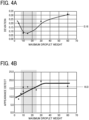
- the average value of the maximum droplet weight on the flow path forming surface 40 and the maximum droplet weight on the flow path forming surface 50 is 8 ⁇ g or more and 25 ⁇ g or less, preferably 10 ⁇ g or more and 15 ⁇ g or less, a deterioration in the appearance of the molded product due to friction between the flow path forming surface and the plastic composition is reduced, the discharge stability of the plastic composition from the flow path outlet port is improved, and the occurrence of uneven thickness of the molded product is prevented.
- the degree of freedom in the flow path design is increased. This makes it easy to create a flow path design in which a clearance to ensure a desired back pressure matches the molded product (the foamed plastic sheet) to be manufactured. Therefore, a molded product in a desired state can be easily obtained. Further, by increasing the degree of freedom in the design of the flow path, the flow path can be designed to be easily cleanable when changing setups.
- the water droplets are caused to deposit on the flow path forming surface within a range of 3 mm upstream from the outlet port of the flow path 30 in a flow direction of the plastic composition, and preferably, at least within this range of 3 mm, the average value of the maximum droplet weight on the flow path forming surface 40 and the maximum droplet weight on the flow path forming surface 50 is kept within the range mentioned above.
- the flow resistance of the plastic composition with respect to the flow path forming surface immediately before foaming can be set within an appropriate range, and an appearance defect of the plastic composition due to friction between the flow path forming surface and the sheet can be prevented, while maintaining the flow stability of the plastic composition.
- a method of measuring the maximum droplet weight at which the droplet does not slide down from the flow path forming surface is not particularly limited and can be appropriately selected according to a purpose. Specifically, the method includes confirming that a droplet in an amount determined in advance can be added dropwise by using a commercially available contact angle meter, a syringe having a micrometer head, and a pipetter. If desired, the method includes confirming a correspondence relation between a droplet volume and a droplet weight by using a commercially available electronic balance.
- water droplets are deposited on the flow path forming surface within a range of 3 mm upstream from the outlet port of the flow path 30 in the flow direction of the plastic composition.
- the droplet volume may be directly estimated by using software provided in various types of contact angle meters.
- a surface of the flow path forming surface on which the water droplet is to be deposited is wiped by using a solvent having strong degreasing power, or an alcohol, a parts cleaner, and the like. It is preferable to repeatedly and thoroughly wipe the surface with a clean cloth until the surface is dry, and avoid applying unnecessary friction after drying. This is to prevent measurement results from varying due to frictional electrification or changes in an adsorbed substance. Further, for the same reason, it is also not preferable to use air blowing after wiping off the solvent.
- the droplet deposition surface of the flow path forming surface is tilted from a state parallel to the horizontal direction to a state parallel to the vertical direction.
- the droplet deposition surface may be tilted by using a rotatably movable stage, or may be tilted by using a crane or a reversing machine.
- the flow path forming surface where the water droplet is to be deposited generally has a curved surface within a range of 3 mm upstream from the outlet port of the flow path 30 in the flow direction of the plastic composition. Therefore, at this time, a virtual plane that contacts the flow path forming surface at the center point of a droplet is treated as the droplet deposition surface and is tilted until a state parallel to the vertical direction. That is, it is sufficient to regard the droplet deposition surface as a plane contacting a curved surface and obtain average data. However, if there is a flat region (a region having a linear shape in FIG. 1 ) of the flow path forming surface within a range of 3 mm upstream from the outlet port of the flow path 30 in the flow direction of the plastic composition, the water droplet is caused to deposit in the flat region.
- the droplet In determining whether a droplet has slid down from the flow path forming surface, the droplet is determined to have slid down when the amount of sliding down of the droplet is 1 mm or more in a period of 1 minute from 3 seconds after the flow path forming surface reaches a vertical position. Further, by comparing an image before tilting the flow path forming surface to a state parallel to the vertical direction and an image after tilting the flow path forming surface to the state parallel to the vertical direction, the water droplet may be determined to have slid down when a downward movement of an upper part of the water droplet in the vertical direction, which forms the contact angle, is confirmed. Note that a method of determining whether a droplet has slid down is not limited to these methods, and any method which can confirm the movement of the entire droplet may be used.
- a contact angle of the first flow path forming surface 40 and the second flow path forming surface 50 with respect to water is not particularly limited and can be appropriately selected according to a purpose, but is preferably 55° or more and less than 110°.
- the contact angle is within this range, the above-mentioned range can be achieved by using a comparably inexpensive treatment, and there is no need to perform a hydrophilic treatment or an expensive water repellent treatment such as fine processing including fractal processing on the flow path surface.
- a method of measuring the contact angle is not particularly limited and can be appropriately selected according to a purpose.
- the contact angle may be measured by a method in conformity with JIS R 3257.
- the contact angle was measured with a droplet in an amount in a range from about 0.5 ⁇ l to about 4 ⁇ l, and if a peak was observed, a maximum value of the peak was used.
- the droplet amount is small, such as a droplet amount below 0.5 ⁇ l, there is a risk of an error in which a low contact angle is obtained due to the influence of the nozzle diameter and the like.
- the droplet amount is large, such as a droplet amount exceeding 4 ⁇ l, there is a risk of an error in which a low contact angle is obtained due to an impact when the liquid separates from the nozzle.
- the droplet amount is preferably about 1.5 ⁇ l when the contact angle is approximately constant regardless of the droplet amount. Note that a nozzle-less contact angle meter may be used to measure the contact angle.
- the angle does not necessarily have to be calculated by the method in conformity with JIS R 3257. As long as consistency is guaranteed, image processing of an image captured of a side surface of a droplet or an image captured of a top surface of a droplet may be used.
- an arithmetic mean roughness Ra of at least one of the flow path forming surfaces including the flow path forming surface 40 and the flow path forming surface 50 is less than 1.5, and a roughness curve element average length Rsm is 60 ⁇ m or more. Further, it is more preferable that the arithmetic mean roughness Ra of the flow path forming surface of the flow path forming surface 40 or the flow path forming surface 50 is less than 1.3, and the roughness curve element average length Rsm is 67 ⁇ m or more. Particularly preferably, the arithmetic mean roughness Ra is 0.2 or more and less than 1.3, and the roughness curve element average length Rsm is 67 ⁇ m or more and less than 106.
- a core portion level difference Rk of at least one of the flow path forming surfaces including the flow path forming surface 40 and the flow path forming surface 50 is 1.0 ⁇ m or more.
- a method of measuring the above-mentioned surface roughness parameters Rsm, Ra, and Rk is not particularly limited.
- the surface roughness parameters Rsm, Ra, and Rk may be measured by using a portable roughness meter such as a VK-X250 manufactured by Keyence Corporation and an SJ-210 manufactured by Mitutoyo Corporation. Examples of measurement conditions when measuring each of the above-described surface roughness parameters Rsm, Ra, and Rk by using the VK-X250 manufactured by Keyence Corporation is described below. Note that the measurement conditions are not limited to those below, as long as the measurement conditions conform to those below and, if there is a correlation relationship between instrumental errors, the correlation relationship is known in advance.
- the HRC hardness of at least one among the first flow path forming surface 40 and the second flow path forming surface 50 is 28 or more. If the HRC hardness is 28 or more, the sliding properties of the flow path forming surface can be maintained over time. Therefore, it is possible to prevent friction between the resin and the flow path while maintaining the quality deviation in the circumferential direction and the quality deviation over time of the molded product, and it is possible to prevent the deterioration of the appearance of the molded product over time. This makes it possible to provide a device having low maintenance cost.
- the HRC hardness can be measured by a method in conformity with JIS Z 2245.
- the method of measuring the HRC hardness is a destructive test. Therefore, as long as it can be confirmed in advance that the HRC hardness of the outermost surface can be estimated correctly, other hardness indicators or the tensile test strength may be referred to, or a value obtained by inspecting extracted material may be used.
- the materials of the first flow path forming member 10 and the second flow path forming member 20 of the flow path forming device 5 are not particularly limited and can be appropriately selected according to a purpose.
- Examples of the materials of the first flow path forming member 10 and the second flow path forming member 20 include, but are not limited to, metal, carbon steel, chrome steel, nickel steel, nickel chromium steel, aluminum, plastic, stainless steel, pre-hardened steel, cemented carbide, and high speed steel, that is, S45C, S50C, S55C, A5052, SS400, SUS304, SUS316, SUS420, SKD11, SKH51, HPM-38, SCM415, SCM435, and SCM440.
- coatings may be applied to the surfaces of the first flow path forming member 10 and the second flow path forming member 20 and the flow path forming surfaces 40 and 50.
- coating methods include, but are not limited to, hard chrome plating, electroless nickel plating, alumite treatment, black dyeing, Parker, carbide film formation, nitride film formation, oxide film formation, DLC treatment, silicone mold release treatment, and fluorine mold release treatment, that is, coatings including Cr, Ni, Ni-P, amorphous alumina, crystallized alumina, zirconia, TiC, TiCN, TiN, WC, PTFE, ETFE, FEP, PCTFE, PFA, PVDF, composite coatings of these materials, and composite coatings obtained by adding functional aids of plastic to these materials.
- a method of forming the materials of the first flow path forming member 10 and the second flow path forming member 20 of the flow path forming device 5 is not particularly limited and can be appropriately selected according to a purpose.
- Examples of the method include, but are not limited to, cutting, rolling, electrical discharge machining, drawing, polishing, painting, vapor deposition, physical vapor deposition (PVD), chemical vapor deposition (CVD), plating, thermal spraying, and etching.
- PVD physical vapor deposition
- CVD chemical vapor deposition
- plating thermal spraying, and etching.
- painting has excellent efficiency when experimentally examining various embodiments. Items examined by painting may be mass-produced by using other methods.
- a painting method it is desirable to have a process of dilution with a solvent, but any painting method may be used, as long as the materials can be processed. From the viewpoint of durability, it is preferable to use a coating that reacts during firing, but the coating is not limited thereto. To maintain the adhesion of the coating, it is preferable to roughen a foundation as much as possible, but the method is not limited thereto. In some cases, it is possible to intentionally form a state where the foundation is exposed and the coating layer remains in a trough portion.
- a method of finishing the first flow path forming member 10 and the second flow path forming member 20 of the flow path forming device 5 is not particularly limited and can be appropriately selected according to a purpose.
- finishing methods include, but are not limited to, a plasma treatment, an ozone treatment, a thermal aging treatment, a chemical aging treatment, a physical aging treatment, a silane coupling treatment, and glass coating. These methods can, for example, stabilize the number of cracks on a surface plated by hard chrome plating or expand the width of the cracks. These methods can also be used to finely control a maximum droplet weight G mentioned above.
- a method of controlling the state of the flow path forming surfaces 40 and 50 by the finishing methods described above may be freely selected from among generally used primer treatments and adhesion improving treatments.
- the thickness of an oxidized layer on the surface may increase and the quality may change over time.
- the thermal aging treatment is effective for stable production.
- the thermal aging treatment is effective for stable production.
- a temperature in the heat treatment is preferably higher than a processing temperature.
- the flow may be unstable when a new product is used, but the performance may stabilize after several tons of material are processed and discharged. In such a case, it is also effective to perform the above-mentioned aging treatment in advance.
- the surface state of the flow path forming surfaces 40 and 50 can be controlled by performing an adjustment described below.
- the adjustment can be implemented by lightly wiping the flow path forming surface with a solvent, immersing the flow path forming surface into a solvent, or cautiously applying a paper of approximately #2000 to the flow path forming surface.
- the direction and the width that can be changed vary depending on the material, and thus, it is desirable to appropriately select the direction and the width experimentally.
- the method of adjusting the maximum droplet weight G and the contact angle by lightly wiping the flow path forming surface with a solvent, immersing the flow path forming surface into a solvent, or cautiously applying a paper of approximately #2000 to the flow path forming surface may be used as a final treatment. Further, the method of adjusting the maximum droplet weight G and the contact angle may be implemented as a pretreatment to improve the adhesion of the various types of coatings applied to the surfaces of the first flow path forming member 10 and the second flow path forming member 20 and the flow path forming surfaces 40 and 50.
- the flow path 30 of the flow path forming device 5 has an annular shape, and the annular shape is not particularly limited and can be appropriately selected according to a purpose.
- the shape include, but are not limited to, a circular ring shape, a polygonal ring shape, and a shape in which the diameter increases toward the outlet port of the flow path.
- the size of the flow path 30 is not particularly limited and can be appropriately selected according to a purpose, and regardless of the shape of the flow path 30, the diameter of a tip end of the flow path outlet port is preferably 70 mm or more and 160 mm or less. This makes it easier to manufacture sheets having an actual foaming ratio range of about 5 to 30 times without corrugating, and also makes it possible to provide a sheet width of 300 mm or more and 1,300 mm or less, which is desirable as a sheet with of the final commercial product.
- a method of forming the shape of the flow path forming surfaces 40 and 50 in the flow path forming device is not particularly limited and can be appropriately selected according to a purpose.
- the shape of the flow path forming surfaces 40 and 50 can be formed by sandblasting, but the method is not limited thereto.
- methods such as electrolysis, chemical etching, and machining using a lathe may also be used.
- the roughness of the flow path forming surfaces 40 and 50 can be controlled by controlling the application time, the injection pressure, the distance to the workpiece, the processing angle, the shape of the media, the material of the media, and the like.
- the roughness of the flow path forming surfaces 40 and 50 may vary due to environmental influences such as the hardness of the outermost surface of the workpiece, the configuration of an application equipment, the degree of deterioration of the media, the nozzle shape (the shape of the outlet port of the flow path), and the like.
- the plastic composition is a material included in a foamed plastic sheet that is molded by using the flow path forming device 5 described above.
- the plastic composition contains at least one type of plastic resin, and preferably contains a filler (also referred to as a foam nucleating agent) and a foaming agent, and may further contain other components, if desired.
- the plastic resin is not particularly limited and can be appropriately selected according to a purpose.
- the plastic resins include, but are not limited to, styrene-based homopolymers such as polystyrene and poly-p-methylstyrene, styrene-based copolymers such as styrene-maleic anhydride copolymer, styrene-acrylonitrile copolymer, styrene-butadiene copolymer, styrene-acrylonitrile-butadiene copolymer, styrene-acrylic acid copolymer, and styrene-methacrylic acid copolymer, styrene-based resins such as mixtures of polystyrene and polyphenylene oxide, and aliphatic polyester resins such as polylactic acid, polyglycolic acid, poly(3-hydroxybutyrate), poly(3-hydroxybutyrate/3-hydroxyhexano
- the aliphatic polyester resins may be synthesized by using an alcohol component or a derivative thereof and an acid component or a derivative thereof. Alternatively, a commercially available product may be used as the aliphatic polyester resin.
- polylactic acid which is a carbon-neutral material and relatively inexpensive, is more preferred.
- polylactic acid is preferred, because polylactic acid has similar properties to conventionally used polystyrene resins and the like, and has a melting point, toughness, and chemical resistance that are higher than in other biodegradable plastics.
- polylactic acid examples include, but are not limited to, a copolymer of D-lactic acid and L-lactic acid, a homopolymer of any one among D-lactic acid (D-form) and L-lactic acid (L-form), and ring-opened polymers of at least one type of lactide selected from the group including D-lactide (D-form), L-lactide (L-form), and DL-lactide.
- D-form D-form
- L-lactic acid L-lactic acid
- These polylactic acids may be used alone or in combination of two or more types.
- the polylactic acid may be appropriately synthesized, or a commercially available product may be used as the polylactic acid.
- the D-form: L-form ratio of the lactic acid included in the polylactic acid is not particularly limited, but it is preferable that any one among the D-form and the L-form of the lactic acid included in the polylactic acid is 95 mol% or more in the polylactic acid.
- a polylactic acid including only one of the optical isomers, the D-form or the L-form, may be used.
- a polylactic acid within this range has high crystallinity, and a foamed sheet manufactured by using such a polylactic acid can be expected to have heat resistance and is suitable for food applications and the like.
- the content of the plastic resin is not particularly limited and can be appropriately selected according to a purpose, but is preferably 90 mass% or more with respect to the total amount of the plastic composition.
- a method of measuring the content of the plastic resin is not particularly limited and can be appropriately selected according to a purpose.
- the content of the plastic resin may be measured by determining the weight ratio of the resin component from the ash determined in conformity with JIS K7250-1.
- a filler (may be referred to as "foam nucleating agent” hereinafter) is included for the purpose of adjusting a foamed state (such as a size, an amount, and an arrangement of cells) of the plastic composition, reducing the cost, and improving the strength.
- the filler is not particularly limited, can be appropriately selected according to a purpose, and examples thereof include inorganic fillers and organic fillers. These fillers may be used alone or in combination of two or more types.
- inorganic fillers include, but are not limited to, talc, kaolin, calcium carbonate, silicate minerals, zinc carbonate, wollastonite, silica, alumina, magnesium oxide, calcium silicate, sodium aluminate, calcium aluminate, sodium aluminosilicate, magnesium silicate, a glass balloon, carbon black, zinc oxide, antimony trioxide, zeolite, hydrotalcite, metal fiber, metal whisker, ceramic whisker, potassium titanate, boron nitride, graphite, glass fiber, and carbon fiber.
- silicate minerals are preferred from the viewpoint of performance and cost.
- silica or a filler whose surface is treated with silica is also preferable, because such fillers have affinity with compressible fluids, which will be described later.
- organic fillers include, but are not limited to, naturally occurring polymers such as starch, cellulose, wood flour, soy pulp, rice husks, and wheat bran, sorbitol compounds, benzoic acid, phosphate ester metal salts, and rosin compounds.
- cellulose is preferred from the viewpoint of low environmental impact.
- the foaming agent is not particularly limited and can be appropriately selected according to a purpose.
- the foaming agent include, but are not limited to, hydrocarbons such as lower alkanes including propane, normal butane, isobutane, normal pentane, isopentane, and hexane, ethers such as dimethyl ether, halogenated hydrocarbons such as methyl chloride and ethyl chloride, and physical foaming agents such as compressible gases (may be referred to as "compressible fluids" hereinafter) including carbon dioxide and nitrogen.
- compressible gases such as carbon dioxide and nitrogen are preferred, because these gases are odorless, can be handled safely, and have a low environmental impact.
- the other components are not particularly limited and may be appropriately selected according to a purpose.
- examples of the other components include, but are not limited to, a cross-linking agent, a thermal stabilizer, an antioxidant, a plasticizer, and a lubricant.
- the cross-linking agent is not particularly limited, can be appropriately selected according to a purpose.
- Preferred examples of the cross-linking agent include, but are not limited to, at least one type selected from an epoxy compound and an isocyanate compound, and the epoxy compound is more preferred.
- a foamed sheet prepared by using an aliphatic polyester resin composition containing such a cross-linking agent can prevent coalescence and bursting of cells, and can improve the foaming ratio.
- a foamed plastic sheet (hereinafter referred to as a foamed sheet) that is formed by foaming a plastic composition when the plastic composition is extruded from the outlet port of the flow path 30 of the flow path forming device 5 will be described.
- the foaming ratio of the foamed sheet as a foamed plastic sheet is preferably 2 times to 50 times, more preferably 5 times to 40 times, and even more preferably 10 times to 30 times.
- the foaming ratio is less than 2 times, the strength is sufficient, but the lightness of the foamed sheet is not good, which is undesirable.
- the foaming ratio is more than 30 times, the lightness is excellent, but the strength is insufficient, which is undesirable.
- a method of measuring the foaming ratio of the foamed sheet is not particularly limited and can be appropriately selected according to a purpose.
- the foaming ratio may be measured by a buoyancy-type specific gravity measuring device.
- the foamed sheet substantially does not contain any volatile components. If the foamed sheet substantially does not contain any volatile components, it is possible to improve the dimensional stability and also reduce the impact on the human body and the environment.
- volatile components include, but are not limited to, organic solvents and foaming agents such as butane. Further, the above-mentioned expression "substantially does not contain” means that volatile components are at or below the detection limit in an analysis described below.
- a part of the foamed sheet is used as a sample, and 2 parts by mass of 2-propanol are added to 1 part by mass of the sample.
- the mixture is dispersed with ultrasonic waves for 30 minutes, and then, stored in a refrigerator (5°C) for one day or longer to obtain an extracted liquid of the volatile components.
- the extracted liquid of the volatile components is analyzed by gas chromatography (GC-14A, manufactured by Shimadzu Corporation) to quantify the volatile components in the foamed sheet. The measurement conditions are described below.
- a part of the foamed sheet is dispersed in a solvent, and an extracted liquid of the volatile components is measured by gas chromatography under the above-described conditions to quantify the organic compounds.
- the foamed sheet "substantially does not contain" volatile components.
- the foamed sheet is selected so that organic compounds having a boiling point of -20°C or higher and lower than 150°C are not detected (are at or below the detection limit), and thus, the foamed sheet can be safely handled without generating odors and the like.
- carbon dioxide and the like which is used as a compressible fluid in which the plastic resin is soaked in a kneading step, may not be removed after the kneading step and used as a foaming agent. If carbon dioxide is used as a compressible fluid in which the plastic composition is soaked in the kneading step and this compressible fluid is used as a foaming agent, it is possible to avoid the use of volatile components as a foaming agent. Therefore, it is easier to obtain a state where volatile components are substantially not contained in the foamed sheet.
- the extrusion molding method includes a kneading step, a foaming step, and other steps.
- the kneading step and the foaming step may be performed by one device (one extruder), or the kneading step and the foaming step may be performed by separate devices (extruders).
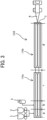
- An extrusion molding device 110 illustrated in FIG. 3 includes a first extruder 110a that performs a kneading step and a second extruder 110b that performs a foaming step. Note that the extrusion molding device 110 may further include devices that perform other steps.
- the first extruder 110a that performs the kneading step receives, from quantitative feeders 1 and 2, a pellet-shaped masterbatch (an intermediary resin composition) manufactured by a kneading device 100 illustrated in FIG.
- the above-mentioned plastic composition is obtained by kneading in the first extruder 110a.
- the above-mentioned flow path forming device 5 is attached to a downstream end portion of the second extruder 110b in a movement direction of the plastic composition.
- the plastic composition extruded by the second extruder 110b passes through the flow path 30 of the flow path forming device 5 illustrated in FIG. 1 , the plastic composition is foamed at the outlet port of the flow path 30, and the above-described foamed sheet is extruded and molded.
- an aliphatic polyester resin as the plastic resin and a cross-linking agent are kneaded at a temperature lower than the melting point of the aliphatic polyester resin in the presence of a compressible fluid to obtain an aliphatic polyester resin composition as the plastic composition.
- the kneading is performed at a temperature lower than the melting point of the aliphatic polyester resin for the following two reasons.
- the first reason is that the aliphatic polyester resin has a property by which the melt viscosity decreases rapidly from the melting point onward, and thus, even if attempting to disperse the additives into the resin by kneading, the additives tend to aggregate and are difficult to disperse.
- the second reason is that, when the aliphatic polyester resin and the cross-linking agent are kneaded at a high temperature, the cross-linking reaction is accelerated, and the aliphatic polyester resin is polymerized, which leads to an increase in the gel fraction of the resin composition.
- a compressible fluid is used to soak the aliphatic polyester resin.
- a compressible fluid By soaking the aliphatic polyester resin in a compressible fluid, it is possible to knead the aliphatic polyester resin and the cross-linking agent in a high-viscosity state at a temperature lower than the melting point of the aliphatic polyester resin, and thus, it is possible to uniformly disperse unreacted additives such as the cross-linking agent in the aliphatic polyester resin.
- a compressible fluid is a fluid whose density changes in response to a change in pressure.
- the compressible fluid include, but are not limited to, a supercritical fluid that exists as a non-condensable high-density fluid in a temperature and pressure region exceeding the limit (critical point) where gas and liquid can coexist, and does not condense even when being compressed.
- Further examples of the compressible fluid include, but are not limited to, liquefied gases obtained by compressing substances that are in a gaseous state at ordinary temperature (25°C) and normal pressure (1 atm), and high-pressure gases (compressible gases) having a pressure of 1/2 or more of the critical pressure.
- substances that can be used as the compressible fluid include, but are not limited to, carbon monoxide, carbon dioxide, dinitrogen monoxide, nitrogen, methane, ethane, propane, 2,3-dimethylbutane, ethylene, and dimethyl ether.
- carbon dioxide is preferable from the following four reasons. That is, the critical pressure of carbon dioxide is about 7.4 MPa, the critical temperature is about 3 1°C, and a supercritical state can be easily reached (a supercritical fluid can be created). Carbon dioxide is nonflammable and easy to handle. As mentioned above, carbon dioxide can be used as a foaming agent. By using carbon dioxide, it is easy to reach a state where the foamed sheet to be molded substantially does not contain volatile components.
- These compressible fluids may be used alone or in combination of two or more types.
- the solubility of the compressible fluid changes depending on the combination of resin type and the compressible fluid, the temperature, and the pressure. Therefore, it is desired to appropriately adjust the supply amount of the compressible fluid.
- the supply amount of carbon dioxide is preferably 2 mass% or more and 30 mass% or less.
- the supply amount of carbon dioxide is 2 mass% or more, it is possible to prevent an issue in which the plasticizing effect becomes limiting. If the supply amount of carbon dioxide is 30 mass% or less, it is not possible to sufficiently disperse additives such as a cross-linking agent, due to an issue in which carbon dioxide and polylactic acid undergo phase separation.
- a continuous process can be adopted, or a batch process can be adopted.
- Examples of the kneading device include, but are not limited to, a single-screw extruder, a twin-screw extruder, a kneader, a shaftless cage-type stirring tank, a VIVOLAC manufactured by Sumitomo Heavy Industries, Ltd., an N-SCR manufactured by Mitsubishi Heavy Industries, Ltd., and a tubular polymerization tank including an SMI,X-type static mixer having double-sided open circle blades or lattice blades manufactured by Hitachi, Ltd, and KENIX-type or SULZER-type blades, which can be used at a viscosity suitable for kneading.
- a self-cleaning polymerization device such as a finisher, an N-SCR, and a twin-screw extruder can be used.
- a finisher and an N-SCR are preferred from the viewpoint of production efficiency, color tone of the resin, stability, and heat resistance.
- FIG. 2 is a schematic diagram illustrating the kneading device 100.
- the kneading device 100 illustrated in FIG. 2 uses a twin-screw extruder (manufactured by JSW, LTD.), and the screw diameter is 42 mm, LID is 48 where L is the screw length and D is the screw diameter.
- the kneading device 100 has a raw material mixing/melting area a, a compressible fluid supply area b, a kneading area c, a compressible fluid removal area d, and a molding processing area e.
- a pellet-shaped aliphatic polyester resin and a cross-linking agent are supplied from a first quantitative feeder 1 and a second quantitative feeder 2, as materials that form the above-described plastic composition.
- a first quantitative feeder 1 and a second quantitative feeder 2 are supplied from a first quantitative feeder 1 and a second quantitative feeder 2, as materials that form the above-described plastic composition.
- fillers and other components thermal stabilizers, antioxidants, plasticizers, and lubricants included in the above-described plastic composition, materials that do not react even at high temperatures may be additionally supplied.
- the temperature of the supplied raw materials is raised.
- the heating temperature is set to a temperature equal to or higher than the melting temperature of the aliphatic polyester resin, and the supplied pellet-shaped aliphatic polyester resin is melted.
- a metering pump 3 serving as a compressible fluid supply portion supplies a compressible fluid to the molten resin to plasticize the molten resin.
- the raw materials supplied in the raw material mixing/melting area a are kneaded.
- the temperature is set so that the viscosity is suitable for kneading the aliphatic polyester resin composition.
- the set temperature varies depending on the specifications of the reaction device, the type of the resin, the structure of the resin, the molecular weight, and the like. Therefore, the temperature is not particularly limited and can be changed as appropriate.
- Mw weight average molecular weight
- kneading is normally performed at a temperature of 10°C to 20°C higher than the melting point of the polylactic acid.
- kneading can be performed at a temperature lower than the melting point of the polylactic acid.
- kneading is performed at a temperature lower than the melting point of the aliphatic polyester resin, and thus, the kneading can be performed at a relatively high viscosity as described above, and additives such as a cross-linking agent can be well dispersed in the resin.
- the temperature is not particularly limited, as long as the temperature is lower than the melting point of the resin. However, in the case of a commercially available polylactic acid, the temperature is preferably set 30°C to 80°C lower than the melting point of the polylactic acid, to suppress the progress of the cross-linking reaction of the cross-linking agent mixed in this area.
- a pressure valve provided in the extruder is opened to discharge the compressible fluid to the outside.
- an intermediary resin composition in which at least an aliphatic polyester resin and a cross-linking agent are mixed is molded and processed into any appropriate shape such as a pellet.
- the pressure in each area within the extruder can be set as appropriate.
- the pressure from the compressible fluid supply area b to the compressible fluid removal area d is 7 MPa.
- the foaming step is a step of expanding the above-mentioned foaming agent to foam the aliphatic polyester resin composition.
- a compressible fluid a compressible gas such as carbon dioxide and nitrogen
- the compressible fluid is expanded by releasing pressure to remove the compressible fluid and foam the aliphatic polyester resin composition.
- the pressure is released by pushing the compressible fluid out from the flow path outlet port of the of the flow path forming device 5.
- the compressible fluid is gradually replaced by air and removed from the foamed sheet.
- the temperature during the foaming step is preferably raised to a temperature close to the melting point of the resin.
- foaming is caused by an operation in which the solubility of the compressible fluid dissolved in the aliphatic polyester composition is reduced by reducing the pressure or increasing the temperature, which results in supersaturation. It is assumed that, by lowering the solubility of the compressible fluid, foamed nuclei are formed mainly at an interface with the foam nucleating agent (filler), and the compressible fluid dissolved in the aliphatic polyester composition diffuses, so that the foamed core grows and forms cells and a foamed body is obtained.
- the foaming process starts from the foam nucleating agent (filler), and thus, a foamed sheet having uniform and fine cells can be manufactured when the foam nucleating agent (filler) is uniformly dispersed in the resin. Even when no foam nucleating agent (filler) is used, a foamed sheet having uniform and fine cells can be manufactured, because a small amount of crystals generated in the kneading area substantially acts as a foam nucleating agent. However, if the crystallization progresses excessively, the fluidity of the composition may decrease and foaming may not easily occur, and thus, it is preferable to add a foam nucleating agent (filler).
- the other steps are not particularly limited and can be appropriately selected according to a purpose, as long as the other steps are steps performed in the production of ordinary plastic foamed sheets, such as a molding step for forming a sheet.
- Examples of the molding step include, but are not limited to, vacuum molding, pressure molding, and press molding.
- a cylindrical masterbatch is molded, and this masterbatch is formed into a sheet shape by the molding step to obtain a foamed sheet.
- FIG. 3 is a diagram illustrating the extrusion molding device 110.
- the extrusion molding device 110 includes the first extruder 110a that performs the kneading step and the second extruder 110b that performs the foaming step.
- the flow path forming device 5 illustrated in FIG. 1 is attached to a downstream end portion of the second extruder 110b in the movement direction of the plastic composition.
- the first extruder 110a and the second extruder 110b are twin-screw extruders (manufactured by JSW, LTD.), similar to the kneading device 100 in FIG. 2 .
- the extrusion molding device 110 has a raw material mixing/melting area a, a compressible fluid supply area b, a kneading area c, and a heating area d.
- raw materials are supplied from the first quantitative feeder 1 and the second quantitative feeder 2 and mixed, and the supplied raw materials are heated to melt the resin.
- the raw materials supplied from the first quantitative feeder 1 and the second quantitative feeder 2 include a masterbatch (an intermediary resin composition mixed with at least an aliphatic polyester resin and a cross-linking agent) molded in the kneading device 100 illustrated in FIG. 2 , a filler, and other components such as the above-mentioned thermal stabilizer, antioxidant, plasticizer, and lubricant.
- a masterbatch an intermediary resin composition mixed with at least an aliphatic polyester resin and a cross-linking agent
- resin pellets are additionally supplied to adjust the concentration of the cross-linking agent to an appropriate value.
- the type of the plastic resin that is additionally supplied is not particularly limited, but the additionally supplied plastic resin is preferably the same aliphatic polyester resin as the plastic resin in the masterbatch. It is preferable to use the same resin as the plastic resin in the masterbatch, because in this case, the resins are mixed uniformly in the kneading step and an unreacted cross-linking agent contained in the resin is also uniformly dispersed.
- the masterbatch already contains a cross-linking agent, however, a cross-linking agent may be further additionally supplied.
- the filler as a foam nucleating agent is added in the extrusion molding device 110.
- the filler may also be added when the masterbatch (the intermediary resin composition) is molded in the kneading device 100 illustrated in FIG. 2 . Further, the filler may be added in both the kneading step when the masterbatch is molded and the kneading step when the foamed sheet is molded.
- the metering pump 3 serving as a compressible fluid supply portion supplies a compressible fluid to the molten resin to plasticize the molten resin.
- the compressible fluid used for soaking when the foamed sheet is molded it is possible to use the compressible fluid used for soaking when the masterbatch (the intermediary resin composition) is molded in the kneading device 100.
- the compressible fluid used for soaking when the foamed sheet is molded carbon dioxide is preferable from the four reasons mentioned above.
- the compressible fluid used for soaking when the foamed sheet is molded may be used as one type alone, or two or more types may be used in combination. As described above, by using the compressible fluid for soaking, it is possible to knead well, even when the viscosity is high.
- the filler the foam nucleating agent
- the filler can be uniformly dispersed in the plastic resin, and a foamed sheet having uniform and fine cells can be manufactured.
- the compressible fluid supplied in the compressible fluid supply area b is used as a foaming agent. If the compressible fluid supplied in the compressible fluid supply area b is used as a foaming agent, kneading and foaming can be performed in a series of processes, which is more preferable as a manufacturing aspect from the viewpoint of reducing a burden to the environment.
- the supply amount of the compressible fluid as described above, when the aliphatic polyester resin composition is 100 parts by mass, the supply amount of carbon dioxide is preferably 2 mass% or more and 30 mass% or less.
- a foaming agent may be used separately from the compressible fluid used for soaking.
- the foaming agent the foaming agents mentioned in the description of the plastic composition above can be used.
- the raw materials supplied in the raw material mixing/melting area a are kneaded at a temperature lower than the melting temperature of the aliphatic polyester resin.
- the aliphatic polyester resin kneaded in the kneading area c of the first extruder 110a is supplied to the heating area d of the second extruder 110b.
- the aliphatic polyester resin supplied from the first extruder 110a is further kneaded.
- the temperature is preferably set so that the temperature of the plastic composition when extruded from the flow path outlet port of the flow path forming device 5 is lower than the melting point of the plastic composition.
- the temperature of the plastic composition when extruded from the flow path outlet port of the flow path forming device 5 is set to a lower temperature than the melting point of the plastic composition, the plastic composition can be thickened, and thus, it is possible to obtain a foamed plastic having a high foaming ratio.
- the aliphatic polyester resin that is further kneaded in the heating area d is extruded into the flow path 30 of the flow path forming device 5 attached to a downstream end portion of the second extruder 110b in the movement direction of the plastic composition. Subsequently, the aliphatic polyester resin passes through the flow path 30 of the flow path forming device illustrated in FIG. 1 and the pressure is released at the outlet port of the flow path 30. Thus, the compressible fluid serving as the foaming agent is expanded and removed, so that an aliphatic polyester resin composition is extruded and foamed. A foamed sheet 4 obtained by extruding and foaming the aliphatic polyester resin composition is wound up on a mandrel.
- the flow path forming device 5 described with reference to FIG. 1 is used as the flow path forming device 5.
- the flow path forming device 5 is used in which the average value of the maximum droplet weight G in a range of 3 mm from the outlet port of the flow path of the first flow path forming surface 40 and the second flow path forming surface 50 is 8 ⁇ g or more and 25 ⁇ g or less.
- the flow resistance of the aliphatic polyester resin composition immediately before foaming with respect to the flow path forming surface can be kept within an appropriate range. Accordingly, as described above, the flow stability of the aliphatic polyester resin composition immediately before foaming is maintained, and the foamed sheet 4 without uneven thickness can be obtained. Further, friction between the flow path forming surface and the aliphatic polyester resin composition is prevented, and a foamed sheet that has good appearance and reduced surface roughness can be obtained.
- an intermediary resin composition (masterbatch) is molded by using the kneading device 100 illustrated in FIG. 2 .
- the intermediary resin composition and an additive such as a filler are kneaded to produce an aliphatic polyester resin composition.
- the configuration is not limited thereto.
- the aliphatic polyester resin composition may be produced in the kneading step of the extrusion molding device 110, without molding the intermediary resin composition (masterbatch).
- the foamed sheet obtained according to the present embodiment may be directly used, or may be used as a manufactured product.
- the foamed sheet of the present embodiment is very light and heat resistant, and thus can be suitably used as a food container and tableware.
- the foamed sheet is suitable as a heat-resistant food container, the foamed sheet is not limited to such an application. Further, the foamed sheet may be directly printed with characters or the like and used.
- a manufactured product using the obtained foamed sheet is not particularly limited, and can be appropriately changed.
- the manufactured product includes a foamed sheet and if desired, includes other components.
- the other components are not particularly limited and can be appropriately selected according to a purpose, as long as the other components are used in general resin products.
- the obtained foamed sheet may be processed to obtain the manufactured product of the present embodiment.
- the processing used to process the foamed sheet is not particularly limited.
- the foamed sheet may be subjected to a process in which the foamed sheet is processed by using a mold to obtain a product.
- a method of processing the sheet by using a mold is not particularly limited, and examples thereof include conventionally known methods for thermoplastic resins, such as vacuum molding, pressure molding, vacuum pressure molding, and press molding.
- Examples of manufactured products include, but are not limited to, packaging containers, trays, tableware, and cutlery. This concept of a manufactured product includes not only a single manufactured product, but also parts made of the manufactured product, such as a tray handle, and products including the manufactured product, such as a tray to which a handle is attached. Other examples of manufactured products include, but are not limited to, bags, stationery, and daily commodities.
- the amount of cross-linking agent in the obtained foamed sheet varies depending on the molecular weight of the resin being used and the molecular weight distribution of the resin.
- the biodegradable resin is preferably adjusted to 3 mass% or less in order not to impair the biodegradability.
- the amount of the foam nucleating agent (filler) in the foamed sheet is preferably adjusted to 10 parts by mass or less. If the amount of the foam nucleating agent exceeds 10 parts by mass, the physical properties of the foamed sheet may be hard and brittle.
- the content of a non-biodegradable foam nucleating agent is preferably lower, and is more preferably adjusted to 1 part by mass or less.
- the content of the biodegradable resin is 90 mass% or more with respect to the total amount of organic substances in the foamed sheet. More preferably, the content of the biodegradable resin is 98 mass% or more.
- the content of the biodegradable resin is 90 mass% or more, even if the polylactic acid biodegrades, it is possible to prevent other components that do not biodegrade from remaining. If the content of the biodegradable resin is less than 90 mass%, it is not possible to obtain good biodegradability.
- Examples of the organic substances in the foamed sheet mainly include biodegradable resins such as polylactic acid.
- biodegradable resins such as polylactic acid.
- other examples of the organic substances include, but are not limited to, organic core materials and cross-linking agents.
- an inorganic core material is used as the foam nucleating agent, the inorganic core material does not correspond to the organic substances.
- the content ratio of polylactic acid in the foamed sheet can be calculated from the ratio of the material being added (the raw material supplied in the raw material mixing/melting area a of the extrusion molding device). If the material ratio is unknown, the components can be identified by performing the following GCMS analysis and comparing with a known polylactic acid as a standard sample, for example. If desired, the content ratio can be calculated by using the area ratio of the spectrum obtained by an NMR measurement and another analysis method in combination.
- the content ratio of the polylactic acid in the foamed sheet can be determined by, for example, performing an analysis using gas chromatography-mass spectrometry (GC-MS) and determining a calibration curve in advance by using a known polylactic acid as a standard sample, to determine the ratio of the polylactic acid in the foamed sheet. Further, at this time, if an organic nucleating agent is identified by searching in a mass spectrum library, it is also possible to prepare a calibration curve to quantify the added amount. If desired, the content can be calculated by using the area ratio of the spectrum obtained by an NMR measurement and another analysis method in combination.
- GC-MS gas chromatography-mass spectrometry
- the first flow path forming member 10 and the second flow path forming member 20 made of the material S45C (manufactured by Misumi Corporation) were processed by sandblasting (using an alumina abrasive medium for blasting manufactured by Monotaro Co., Ltd., processing angle of about 45 degrees) to form the shape of the flow path illustrated in FIG. 1 .
- sandblasting using an alumina abrasive medium for blasting manufactured by Monotaro Co., Ltd., processing angle of about 45 degrees
- about 100 ⁇ m of a silicone-based release coating was applied to the flow path forming surfaces 40 and 50 processed by sandblasting, and the flow path forming surfaces 40 and 50 were baked.
- the flow path forming surfaces 40 and 50 were wiped with toluene. Finally, the flow path forming surfaces 40 and 50 were processed with a #2000 paper to manufacture the first flow path forming surface 40 and the second flow path forming surface 50.
- the contact angle was measured by the contact angle measurement method described above.
- the contact angle measurement method described above is a measurement method in which the measurement error is not zero. Therefore, the contact angle was measured three times while changing the position within a range of 3 mm from the outlet port of the flow path 30 in the first flow path forming surface 40 and the second flow path forming surface 50. The variation was checked, and if the variation was outside a specified range, the number of measurements was further increased. The average value of these measured values was calculated to obtain the contact angle. The obtained contact angle was 88.2°.
- the arithmetic mean roughness Ra and the roughness curve element average length Rsm of the first flow path forming surface 40 and the second flow path forming surface 50 at a location within a range of 3 mm from the outlet port of the flow path 30 were measured by using the above-described method of measuring each of the surface roughness parameters Rsm, Ra, and Rk.
- the above-described method of measuring each of the surface roughness parameters Rsm, Ra, and Rk is also a measurement method in which the measurement error is not zero. Therefore, similarly to the measurement of the contact angle, the measurement was performed three times while changing the position to confirm the variation, and if the variation was large, the number of measurements was further increased.
- the average value of these measured values was calculated to obtain the arithmetic mean roughness Ra and the roughness curve element average length Rsm.
- the arithmetic mean roughness Ra was 1.29 ⁇ m, and the roughness curve element average length Rsm was 91.6 ⁇ m.
- the same process may be performed on the flow path forming surface in the vicinity of the outlet port of the flow path (in a range of 3 mm from the outlet port of the flow path 30), and the measurement may be performed at a location where the surface state is likely to be equivalent to that near the outlet port of the flow path.
- a test piece or the like that is subjected to the same treatment as the surface in the vicinity of the outlet port of the flow path (in a range of 3 mm from the outlet port of the flow path 30) may be prepared and measured instead.
- the first flow path forming surface 40 and the second flow path forming surface 50 may be processed in the same lot and the measured value of one of the flow path forming surfaces may be used instead.
- Example 2 is similar to Example 1, except that the coating material of the first flow path forming surface 40 and the second flow path forming surface 50 was changed from a silicone-based release coating to a fluorine-based release coating.
- the maximum droplet weight G was measured for each of the flow path forming surfaces 40 and 50 similarly to Example 1, and the average value of the maximum droplet weight G was 10 ⁇ g. Further, the average value of the contact angle was 83.3°, the average value of the arithmetic mean roughness Ra was 1.26 ⁇ m, and the average value of the roughness curve element average length Rsm was 105 ⁇ m.
- Example 3 is similar to Example 1, except that the material of each of the flow path forming members 10 and 20 was changed from S45C to a hard chrome plating.
- the maximum droplet weight G was measured for each of the flow path forming surfaces 40 and 50 similarly to Example 1, and the average value of the maximum droplet weight G was 15 ⁇ g. Further, the average value of the contact angle was 60.3°, the average value of the arithmetic mean roughness Ra was 0.21 ⁇ m, and the average value of the roughness curve element average length Rsm was 67.7 ⁇ m.
- Example 4 is similar to Example 2, except that the wiping operation after aging was performed by using a solvent equivalent to hexane.
- the maximum droplet weight G was measured for each of the flow path forming surfaces 40 and 50 similarly to Example 1, and the average value of the maximum droplet weight G was 8 ⁇ g. Further, the average value of the contact angle was 106.6°, the average value of the arithmetic mean roughness Ra was 1.35 ⁇ m, and the average value of the roughness curve element average length Rsm was 122.8 ⁇ m.
- Example 5 is similar to Example 1, except that the sample was processed by using a #2000 paper for a longer time than in Example 1.
- the maximum droplet weight G was measured for each of the flow path forming surfaces 40 and 50 similarly to Example 1, and the average value of the maximum droplet weight G was 25 ⁇ g. Further, the average value of the contact angle was 57.6°, the average value of the arithmetic mean roughness Ra was 1.02 ⁇ m, and the average value of the roughness curve element average length Rsm was 138.0 ⁇ m.
- Comparative Example 1 is similar to Example 2, except that, after the coating and firing, no treatment (aging treatment, treatment with paper) was performed and the product was left in a new state.
- the maximum droplet weight G was measured for each of the flow path forming surfaces 40 and 50 similarly to Example 1, and the average value of the maximum droplet weight G was 5 ⁇ g. Further, the average value of the contact angle was 102°, the average value of the arithmetic mean roughness Ra was 1.24 ⁇ m, and the average value of the roughness curve element average length Rsm was 99.4 ⁇ m.
- Comparative Example 2 is similar to Example 1, except that the sample was processed by using a #1000 paper, instead of a #2000 paper.
- the maximum droplet weight G was measured for each of the flow path forming surfaces 40 and 50 similarly to Example 1, and the average value of the maximum droplet weight G was 30 ⁇ g. Further, the average value of the contact angle was 91.2°, the average value of the arithmetic mean roughness Ra was 1.57 ⁇ m, and the average value of the roughness curve element average length Rsm was 75.2 ⁇ m.
- the first flow path forming surface 40 and the second flow path forming surface 50 were manufactured by sandblasting only portions of the first flow path forming member 10 and the second flow path forming member 20 made of the material S45C that form the flow path forming surfaces.
- the maximum droplet weight G was measured for each of the flow path forming surfaces 40 and 50 similarly to Example 1, and the average value of the maximum droplet weight G was 60 ⁇ g. Further, the average value of the contact angle was 121°, the average value of the arithmetic mean roughness Ra was 2.07 ⁇ m, and the average value of the roughness curve element average length Rsm was 52.4 ⁇ m.
- the temperatures in each area were as follows.
- Raw material mixing/melting area a and compressible fluid supply area b 190°C
- kneading area c 130°C
- compressible fluid removal area d 190°C
- molding processing area e 190°C.
- the pressure in each zone was 10.0 MPa from the compressible fluid supply area b to the kneading area c
- the pressure in the compressible fluid removal area d was 0.5 MPa to obtain an intermediary resin composition.
- the foamed sheet was formed at a total flow rate of 30 kg/hr, of which 1.5 kg/hr was the flow rate of carbon dioxide and 20 kg/hr was the flow rate of polylactic acid A.
- the areas a, b, and c were kept at the same temperature as used for kneading.
- the temperature of area d was 150°C.
- the pressure in the flow path 30 of the flow path forming device 5 was set to 5 MPa.
- a foamed sheet having a thickness of 1000 ⁇ m was molded.
- the bulk density, the deviation, and the appearance of the obtained foamed sheet were evaluated.
- the appearance of the foamed sheet was evaluated as described below.
- the front surface and the back surface of the obtained foamed sheet were analyzed by using image processing, and an index was used to quantify an appearance defect.
- the appearance was visually evaluated as having a defect, when the size and the width of foreign matter in a solid state present on the sheet surface were large, and the difference in brightness from the background was large. Therefore, people visually evaluated about 100 samples in advance and used human senses to rank the samples in terms of defects in the appearance. An image processing algorithm was fitted to achieve the highest degree of agreement and quantify the appearance defect. A conventional evaluation by visual ranking may be used. However, the present index was used in the evaluation from the viewpoint of efficiency and reproducibility.
- the appearance defect was analyzed and quantified by the image processing described above. The appearance was evaluated based on whether the appearance was less than 16, which is a range in which the sample can be used as a product.
- the foamed sheet was allowed to stand for 24 hours or more in an environment adjusted to a temperature of 23°C and a relative humidity of 50%, and a test piece of 50 mm x 50 mm was cut out from the foamed sheet.
- the weight (g) of the foamed sheet in the atmosphere was accurately weighed for the cut test piece, and the obtained value was divided by the sheet area of 50 mm x 50 mm to determine the sheet weight per unit area.
- the standard deviation of 12 pieces of data obtained by performing the above-described process at 12 locations in a TD direction (a width direction of the foamed sheet, a direction perpendicular to the extrusion direction) was divided by the average value of the 12 points, and the obtained value was used as the deviation.
- the deviation was evaluated based on whether the deviation was less than 0.16, which is a range in which the sample can be used as a product.
- the deviation of the foamed sheet is more preferably less than 0.10, and even more preferably less than 0.08.
- the sheet weight per unit area is not particularly limited, and the evaluation may be based on the foaming ratio, the thickness, and the like. Further, the spatial resolution does not need to be 12 points. A smaller number of measurements can be used, as long as the resolution is set in advance, so that the phenomenon can be correctly identified and the value of the product can be estimated.
- FIGS. 4A and 4B are a graph of the results of the verification experiment.
- Table 1 Contact angle (°) Ra ( ⁇ m) Rsm ( ⁇ m) Droplet weight ( ⁇ g) Bulk density (g/cm 3 ) Deviation (-) Appearance (-) Evaluation
- Example 2 83.3 1.26 105 10 0.103 0.078 13.2 Good
- Example 3 60.3 0.21 67.7 15 0.125 0.068 15.9 Good
- Example 4 106.0 1.35 122.8 8 0.076 0.128 12.9 Good
- Comparative Example 1 102 1.24 99.4 5 0.125 0.196 8.3 Fail Comparative Example 2 91.2 1.57 75.2 30 0.120 0.220 19.4 Fail Comparative Example 3 121 2.07 52.4 60 0.123 0.313 16.6 Fail
- the average value of the maximum droplet weight G was 5 ⁇ g, and thus, the state in Comparative Example 1 is considered to be a state in which the plastic composition was sliding too much on the flow path forming surface.
- the back pressure inside the flow path decreases, which makes it impossible to extrude the plastic composition well, causes the plastic composition to wrap around in the flow path in a direction perpendicular to the extrusion direction, and is considered to lead to an unstable flow rate of the plastic composition to be extruded from the outlet port of the flow path. Therefore, it is considered that, even at a high contact angle of 102°, it is not possible to stably discharge the plastic composition from the outlet port of the flow path. As a result, it is considered that it is not possible to suppress the uneven thickness of the molded foamed sheet and the deviation exceeded 0.16.
- the plastic composition does not easily slide on the flow path forming surface, so that the flow resistance in the flow path is unbalanced, and the flow rate of the plastic composition extruded from the outlet port of the flow path is unstable. As a result, the deviation was 0.16 or more, and it is considered that also the deviation failed to satisfy the standard.
- Examples 1 to 5 in which the average value of the maximum droplet weight G was from 8 ⁇ g to 25 ⁇ g, satisfied the standards for both the deviation and the appearance, and were evaluated as "good.” Further, from the graphs illustrated in FIGS. 4A and 4B , it was confirmed that, if the average value of the maximum droplet weight G was from 8 ⁇ g to 25 ⁇ g, both the deviation and the appearance satisfied the standard. This is because, in Examples 1 to 5, it is considered that it was possible maintain the sliding properties of the flow path forming surface with respect to the plastic composition within an appropriate range, prevent the back pressure within the flow path from decreasing, and maintain a constant flow resistance within the flow path. Accordingly, the flow rate of the plastic composition extruded from the outlet port of the flow path was stabilized, and the occurrence of uneven thickness was suppressed, and thus, it is considered that the deviation satisfied the standard (less than 0.16).
- the plastic composition is prevented from rubbing against the flow path forming surface at the outlet port of the flow path, and is discharged smoothly, so that it is possible to prevent the surface of the foamed sheet from becoming rough.
- the numerical value of the appearance defect satisfies the standard (less than 16).
- the arithmetic mean roughness Ra of the flow path forming surface was less than 1.5
- the roughness curve element average length Rsm was 60 ⁇ m or more
- a flow path forming device 5 including a first flow path forming member 10 having a first flow path forming surface 40 and a second flow path forming member 20 and in which the first flow path forming member 10 and the second flow path forming member 20 having a second flow path forming surface 50, the first flow path forming surface 40 of the first flow path forming member 10 and the second flow path forming surface 50 of the second flow path forming member 20 form a flow path 30 through which a plastic composition flows, and when a water droplet is deposited on a droplet deposition surface of each of the first flow path forming surface 40 and the second flow path forming surface 50, where the droplet deposition surface is in a range an outlet port of the flow path 30 to 3 mm upstream in a flow direction of at least the plastic composition, and the droplet deposition surface on which the water droplet is deposited is tilted from a state parallel to a horizontal direction to a state parallel to a vertical direction, to measure a maximum droplet weight G at which the water droplet does not slide
- a contact angle of the flow path forming surface with a plastic composition such as a molten resin is regulated to prevent the occurrence of uneven thickness of a molded product and to improve the appearance of the molded product.
- a contact angle is adjusted to an appropriate range, it may not be possible to maintain the pressure in the vicinity of an outlet port of the flow path well, so that the uneven thickness of the molded product may be worsen or the surface of the molded product may become rough and deteriorate the appearance. The reason therefore is considered that the above-mentioned contact angle is insufficient as an index value indicating the sliding properties of the flow path forming surface.
- the maximum droplet weight G is used as the index value indicating the sliding properties of the flow path forming surface.
- the maximum droplet weight G is a maximum droplet weight at which a water droplet does not slide down from a droplet deposition surface, when a water droplet is deposited on the droplet deposition surface of the flow path forming surface and the droplet deposition surface is tilted from a state parallel to a horizontal direction to a state parallel to a vertical direction. If the flow path forming surface has good sliding properties, water droplets slide down easily, and the maximum droplet weight G is reduced. On the other hand, if the flow path forming surface has poor sliding properties, water droplets do not easily slide down, and the maximum droplet weight G increases. Therefore, by specifying the maximum droplet weight G mentioned above, the sliding properties of the flow path forming surface with respect to the plastic composition can be set within a more appropriate range than in a case where the contact angle is used to specify the sliding properties.
- the average value of the maximum droplet weight G on the first flow path forming surface 40 and the maximum droplet weight G on the second flow path forming surface 50 is 10 ⁇ g or more and 15 ⁇ g or less.
- the deviation can be reduced to a value of 0.08 or less, and the uneven thickness of the molded product can be prevented in a good manner.
- At least one of the first flow path forming surface 40 and the second flow path forming surface 50 has a contact angle with water of 55° or more and less than 110°.
- the flow path forming surface can be formed by a relatively inexpensive process.
- At least one of the first flow path forming member surface 40 and the second flow path forming surface 50 has an arithmetic mean roughness Ra of less than 1.5 and a roughness curve element average length Rsm of 60 ⁇ m or more.
- the surface of the molded product such as a foamed sheet, is prevented from being roughened when the roughness of the flow path forming surface is transferred thereto, and deterioration of the appearance of the molded product is prevented.
- the flow path forming device 5 extrudes a plastic composition from the outlet port of the flow path of the flow path forming device 5.
- extrusion molding is performed which can produce a molded product having good appearance and in which uneven thickness is prevented.
- the extrusion device extrudes at least one type of a nonflammable gas and the plastic composition from the outlet port of the flow path of the flow path forming device at a temperature lower than a melting point of the plastic composition to manufacture a foamed plastic.
- a foam nucleating agent such as filler can be uniformly dispersed in a plastic resin, and a foamed sheet having uniform and fine cells can be manufactured.
- the extrusion device extrudes the plastic composition from the outlet port of the flow path of the flow path forming device to manufacture a molded product including 90 mass percent or more of a biodegradable resin.
- a molded product having good biodegradability can be manufactured.
- the biodegradable resin includes polylactic acid.
- a molded product can be obtained which have a melting point, toughness, chemical resistance, and the like, that are higher than those of other biodegradable plastics.
- Aspect 9 a foamed plastic sheet is molded by the extrusion device according to any one of Aspects 6 to 8.
- a foamed plastic sheet can be obtained which has good appearance and in which thickness unevenness is prevented.
Landscapes
- Engineering & Computer Science (AREA)
- Mechanical Engineering (AREA)
- Manufacturing & Machinery (AREA)
- Extrusion Moulding Of Plastics Or The Like (AREA)
- Manufacture Of Porous Articles, And Recovery And Treatment Of Waste Products (AREA)
- Molding Of Porous Articles (AREA)
Applications Claiming Priority (1)
| Application Number | Priority Date | Filing Date | Title |
|---|---|---|---|
| JP2023090261A JP2024172501A (ja) | 2023-05-31 | 2023-05-31 | 流路形成装置、押出装置及び発泡プラスチックシート |
Publications (1)
| Publication Number | Publication Date |
|---|---|
| EP4470746A1 true EP4470746A1 (de) | 2024-12-04 |
Family
ID=91082242
Family Applications (1)
| Application Number | Title | Priority Date | Filing Date |
|---|---|---|---|
| EP24175722.8A Pending EP4470746A1 (de) | 2023-05-31 | 2024-05-14 | Strömungswegformungsvorrichtung und extrusionsformungsvorrichtung |
Country Status (4)
| Country | Link |
|---|---|
| US (1) | US20240399640A1 (de) |
| EP (1) | EP4470746A1 (de) |
| JP (1) | JP2024172501A (de) |
| CN (1) | CN119058055A (de) |
Citations (3)
| Publication number | Priority date | Publication date | Assignee | Title |
|---|---|---|---|---|
| DE4304281A1 (en) * | 1992-02-13 | 1993-09-02 | Fuji Photo Film Co Ltd | Film coating appts. for tape or strip materials - has extrusion head with exit having wavy line profile to aid distribution and achieve uniform film thickness |
| JP2896832B2 (ja) | 1993-07-27 | 1999-05-31 | 積水化成品工業株式会社 | 熱可塑性樹脂押出発泡体用金型 |
| EP4249209A1 (de) * | 2022-03-23 | 2023-09-27 | Ricoh Company, Ltd. | Strömungswegformungsvorrichtung und extrusionsformungsvorrichtung |
-
2023
- 2023-05-31 JP JP2023090261A patent/JP2024172501A/ja active Pending
-
2024
- 2024-05-14 EP EP24175722.8A patent/EP4470746A1/de active Pending
- 2024-05-16 US US18/665,938 patent/US20240399640A1/en active Pending
- 2024-05-28 CN CN202410674937.0A patent/CN119058055A/zh active Pending
Patent Citations (3)
| Publication number | Priority date | Publication date | Assignee | Title |
|---|---|---|---|---|
| DE4304281A1 (en) * | 1992-02-13 | 1993-09-02 | Fuji Photo Film Co Ltd | Film coating appts. for tape or strip materials - has extrusion head with exit having wavy line profile to aid distribution and achieve uniform film thickness |
| JP2896832B2 (ja) | 1993-07-27 | 1999-05-31 | 積水化成品工業株式会社 | 熱可塑性樹脂押出発泡体用金型 |
| EP4249209A1 (de) * | 2022-03-23 | 2023-09-27 | Ricoh Company, Ltd. | Strömungswegformungsvorrichtung und extrusionsformungsvorrichtung |
Non-Patent Citations (1)
| Title |
|---|
| ANONYMOUS MOHAMADREZA ET AL: "Determination of the Sliding Angle of Water Drops on Surfaces from Friction Force Measurements - PMC", LANGMUIR, vol. 38, no. 6, 15 February 2022 (2022-02-15), US, pages 2132 - 2136, XP093207829, ISSN: 0743-7463, Retrieved from the Internet <URL:https://www.ncbi.nlm.nih.gov/pmc/articles/PMC8851890/> [retrieved on 20240923], DOI: 10.1021/acs.langmuir.1c03206 * |
Also Published As
| Publication number | Publication date |
|---|---|
| JP2024172501A (ja) | 2024-12-12 |
| US20240399640A1 (en) | 2024-12-05 |
| CN119058055A (zh) | 2024-12-03 |
Similar Documents
| Publication | Publication Date | Title |
|---|---|---|
| JP7639645B2 (ja) | 発泡シート、製造物、成形体及び発泡シートの製造方法 | |
| JP2021134348A (ja) | 発泡体、発泡シート、製造物、及び発泡シートの製造方法 | |
| EP4059695A1 (de) | Matrize zum strangpressen, kunststoffherstellungsvorrichtung und verfahren zur herstellung von kunststoff | |
| EP4249209A1 (de) | Strömungswegformungsvorrichtung und extrusionsformungsvorrichtung | |
| EP4470746A1 (de) | Strömungswegformungsvorrichtung und extrusionsformungsvorrichtung | |
| JP2022180468A (ja) | 発泡シート、製造物及び発泡シートの製造方法 | |
| JP2021116412A (ja) | 発泡シート、製造物、及び発泡シートの製造方法 | |
| JP2023143672A (ja) | 流路形成装置、及び押出成形装置 | |
| JP2023143671A (ja) | 流路形成装置、及び押出成形装置 | |
| EP4079489A1 (de) | Form zum strangpressen, kunststoffherstellungsgerät und verfahren zur herstellung von kunststoff | |
| EP4249208A1 (de) | Strömungswegformungsvorrichtung und extrusionsformungsvorrichtung | |
| JP2022083081A (ja) | 発泡シート、製造物及び発泡シートの製造方法 | |
| EP4361205A1 (de) | Geschäumte polymilchsäurefolie, verfahren zur herstellung einer geschäumten polymilchsäurefolie und produkt | |
| JP2023140753A (ja) | ポリ乳酸樹脂組成物、発泡シート、発泡シートの製造方法、発泡シートを含む製造物、及び成形体 | |
| JP2014051682A (ja) | ポリオレフィン系樹脂発泡シート | |
| JP2023140273A (ja) | 樹脂発泡体製造装置及び樹脂発泡体の製造方法 | |
| CN116803659A (zh) | 流路形成装置及挤出成型装置 | |
| EP4252997B1 (de) | Vorrichtung zur herstellung von harzschaum und verfahren zur herstellung von harzschaum | |
| CN116803660A (zh) | 流路形成装置及挤出成型装置 | |
| EP4119606A1 (de) | Schaumplatte, produkt und verfahren zum produzieren einer schaumplatte | |
| JP2024065942A (ja) | 発泡シート及びその製造方法、並びに、製造物 | |
| US12043717B2 (en) | Foam sheet, product, formed product, and method for producing foam sheet | |
| JP2023110831A (ja) | 発泡シート | |
| US20090118385A1 (en) | Process for Production of Foamed Resin Sheet | |
| JP7143929B2 (ja) | 発泡シート、製造物及び発泡シートの製造方法 |
Legal Events
| Date | Code | Title | Description |
|---|---|---|---|
| PUAI | Public reference made under article 153(3) epc to a published international application that has entered the european phase |
Free format text: ORIGINAL CODE: 0009012 |
|
| STAA | Information on the status of an ep patent application or granted ep patent |
Free format text: STATUS: REQUEST FOR EXAMINATION WAS MADE |
|
| 17P | Request for examination filed |
Effective date: 20240514 |
|
| AK | Designated contracting states |
Kind code of ref document: A1 Designated state(s): AL AT BE BG CH CY CZ DE DK EE ES FI FR GB GR HR HU IE IS IT LI LT LU LV MC ME MK MT NL NO PL PT RO RS SE SI SK SM TR |