EP4468372A2 - Fotovoltaisches modul, herstellungsverfahren für fotovoltaisches modul und bearbeitungsvorrichtung - Google Patents
Fotovoltaisches modul, herstellungsverfahren für fotovoltaisches modul und bearbeitungsvorrichtung Download PDFInfo
- Publication number
- EP4468372A2 EP4468372A2 EP23188341.4A EP23188341A EP4468372A2 EP 4468372 A2 EP4468372 A2 EP 4468372A2 EP 23188341 A EP23188341 A EP 23188341A EP 4468372 A2 EP4468372 A2 EP 4468372A2
- Authority
- EP
- European Patent Office
- Prior art keywords
- region
- photovoltaic module
- solar cell
- solar cells
- electrode lines
- Prior art date
- Legal status (The legal status is an assumption and is not a legal conclusion. Google has not performed a legal analysis and makes no representation as to the accuracy of the status listed.)
- Pending
Links
Images




Classifications
-
- H—ELECTRICITY
- H10—SEMICONDUCTOR DEVICES; ELECTRIC SOLID-STATE DEVICES NOT OTHERWISE PROVIDED FOR
- H10F—INORGANIC SEMICONDUCTOR DEVICES SENSITIVE TO INFRARED RADIATION, LIGHT, ELECTROMAGNETIC RADIATION OF SHORTER WAVELENGTH OR CORPUSCULAR RADIATION
- H10F19/00—Integrated devices, or assemblies of multiple devices, comprising at least one photovoltaic cell covered by group H10F10/00, e.g. photovoltaic modules
- H10F19/90—Structures for connecting between photovoltaic cells, e.g. interconnections or insulating spacers
- H10F19/902—Structures for connecting between photovoltaic cells, e.g. interconnections or insulating spacers for series or parallel connection of photovoltaic cells
- H10F19/908—Structures for connecting between photovoltaic cells, e.g. interconnections or insulating spacers for series or parallel connection of photovoltaic cells for back-contact photovoltaic cells
-
- H—ELECTRICITY
- H10—SEMICONDUCTOR DEVICES; ELECTRIC SOLID-STATE DEVICES NOT OTHERWISE PROVIDED FOR
- H10F—INORGANIC SEMICONDUCTOR DEVICES SENSITIVE TO INFRARED RADIATION, LIGHT, ELECTROMAGNETIC RADIATION OF SHORTER WAVELENGTH OR CORPUSCULAR RADIATION
- H10F19/00—Integrated devices, or assemblies of multiple devices, comprising at least one photovoltaic cell covered by group H10F10/00, e.g. photovoltaic modules
- H10F19/90—Structures for connecting between photovoltaic cells, e.g. interconnections or insulating spacers
- H10F19/902—Structures for connecting between photovoltaic cells, e.g. interconnections or insulating spacers for series or parallel connection of photovoltaic cells
- H10F19/904—Structures for connecting between photovoltaic cells, e.g. interconnections or insulating spacers for series or parallel connection of photovoltaic cells characterised by the shapes of the structures
-
- H—ELECTRICITY
- H10—SEMICONDUCTOR DEVICES; ELECTRIC SOLID-STATE DEVICES NOT OTHERWISE PROVIDED FOR
- H10F—INORGANIC SEMICONDUCTOR DEVICES SENSITIVE TO INFRARED RADIATION, LIGHT, ELECTROMAGNETIC RADIATION OF SHORTER WAVELENGTH OR CORPUSCULAR RADIATION
- H10F19/00—Integrated devices, or assemblies of multiple devices, comprising at least one photovoltaic cell covered by group H10F10/00, e.g. photovoltaic modules
- H10F19/80—Encapsulations or containers for integrated devices, or assemblies of multiple devices, having photovoltaic cells
-
- H—ELECTRICITY
- H10—SEMICONDUCTOR DEVICES; ELECTRIC SOLID-STATE DEVICES NOT OTHERWISE PROVIDED FOR
- H10F—INORGANIC SEMICONDUCTOR DEVICES SENSITIVE TO INFRARED RADIATION, LIGHT, ELECTROMAGNETIC RADIATION OF SHORTER WAVELENGTH OR CORPUSCULAR RADIATION
- H10F19/00—Integrated devices, or assemblies of multiple devices, comprising at least one photovoltaic cell covered by group H10F10/00, e.g. photovoltaic modules
- H10F19/90—Structures for connecting between photovoltaic cells, e.g. interconnections or insulating spacers
- H10F19/902—Structures for connecting between photovoltaic cells, e.g. interconnections or insulating spacers for series or parallel connection of photovoltaic cells
-
- H—ELECTRICITY
- H10—SEMICONDUCTOR DEVICES; ELECTRIC SOLID-STATE DEVICES NOT OTHERWISE PROVIDED FOR
- H10F—INORGANIC SEMICONDUCTOR DEVICES SENSITIVE TO INFRARED RADIATION, LIGHT, ELECTROMAGNETIC RADIATION OF SHORTER WAVELENGTH OR CORPUSCULAR RADIATION
- H10F77/00—Constructional details of devices covered by this subclass
- H10F77/20—Electrodes
- H10F77/206—Electrodes for devices having potential barriers
- H10F77/211—Electrodes for devices having potential barriers for photovoltaic cells
- H10F77/219—Arrangements for electrodes of back-contact photovoltaic cells
-
- Y—GENERAL TAGGING OF NEW TECHNOLOGICAL DEVELOPMENTS; GENERAL TAGGING OF CROSS-SECTIONAL TECHNOLOGIES SPANNING OVER SEVERAL SECTIONS OF THE IPC; TECHNICAL SUBJECTS COVERED BY FORMER USPC CROSS-REFERENCE ART COLLECTIONS [XRACs] AND DIGESTS
- Y02—TECHNOLOGIES OR APPLICATIONS FOR MITIGATION OR ADAPTATION AGAINST CLIMATE CHANGE
- Y02E—REDUCTION OF GREENHOUSE GAS [GHG] EMISSIONS, RELATED TO ENERGY GENERATION, TRANSMISSION OR DISTRIBUTION
- Y02E10/00—Energy generation through renewable energy sources
- Y02E10/50—Photovoltaic [PV] energy
Definitions
- the present disclosure relates to the technical field of photovoltaic power generation, and in particular, to a photovoltaic module, a manufacturing method for a photovoltaic module, and a machining device.
- the present disclosure provides a photovoltaic module, a manufacturing method for a photovoltaic module, and a machining device to solve the problem that cold soldering easily occurs at connection points of solar cells.
- Some embodiments of the present disclosure provide a photovoltaic module, the photovoltaic module including:
- the second region has a width less than or equal to 30 ⁇ m.
- the second region has a surface pore density less than that of the first region.
- At least one recessed portion is arranged on a surface of the first region.
- an arrangement density of the at least one recessed portion an arrangement density ranges from 100 pcs/mm 2 to 2000 pcs/mm 2 .
- a projection of the at least one recessed portion is located outside projections of the electrode line.
- the at least one recessed portion comprises a plurality of recessed portions arranged on the surface of the first region, the recessed portions are arranged apart from each other on a surface of the first region.
- the at least one recessed portion comprises a plurality of recessed portions arranged on the surface of the first region, and adjacent recessed portions of the plurality of recessed portions (133) are interconnected with each other.
- a projection of each of the at least one recessed portion in a corresponding solar cell is in a shape of a circle or an ellipse.
- a projection of each of the at least one recessed portion in the solar cell has a size ranging from 3 ⁇ m to 15 ⁇ m along a width direction of the photovoltaic module.
- the first region is provided with a solder paste.
- Some embodiments of the present disclosure further provide a method for manufacturing a photovoltaic module, the photovoltaic module including a solar cell string, a back sheet, an adhesive film, and photovoltaic glass, and the solar cell string including solar cells, electrode lines, and connecting members, wherein the method includes: placing the connecting members in soldering regions of the solar cells; placing the solar cells with the connecting members on an operating platform; placing each of the the electrode lines on a side of a corresponding solar cell provided with the connecting members on thereon side; heating the electrode lines and the connecting members to obtain the solar cell string; and laminating the back sheet, the adhesive film, the solar cell strings, and the photovoltaic glass to obtain the photovoltaic module.
- each of the solar cells includes a positive busbar and a negative busbar, the positive busbars and the negative busbars are alternately arranged along a width direction of the photovoltaic module, and when the solar cells with the connecting members are placed on the operating platform, and the method for manufacturing a photovoltaic module includes: rotating one of two adjacent solar cells by 180° such that, in the adjacent solar cells, the positive busbar of one of the two adjacent solar cells and the negative busbar of the other of the two adjacent solar cells are located on a same straight line along a length direction of the photovoltaic module.
- the heating the electrode lines and the connecting members to obtain the solar cell string is performed at a heating temperature ranging from 130°C to 220°C for 1.5 s to 6 s..
- the heating the electrode lines and the connecting members to obtain the solar cell string is performed at a heating temperature ranging from 230°C to 240°C, for no more than 5 s.
- Some embodiments of the present disclosure further provide a machining device, for manufacturing a photovoltaic module, the photovoltaic module including solar cells, electrode lines, and connecting members, and the machining device includes: an operating platform, the solar cells being located on a surface of the operating platform; a pressing tool, the pressing tool being located on one side of the operating platform where the solar cells are placed; and a heating apparatus, the heating apparatus being configured to heat the solar cells and the connecting members.
- the heating apparatus is located in the operating platform, and the solar cells are placed in the heating apparatus.
- the heating apparatus is a curing furnace, and the operating platform is capable of entering the curing furnace;
- the curing furnace including a heating member, and the heating member being located on a side of a corresponding solar cell away from the operating platform.
- the pressing tool includes a bracket and abutting members, and the bracket is arranged parallel to each of the electrode lines along a height direction of the machining device electrode line, and each of the abutting members has one end connected to the bracket and another end capable of abutting against one of the electrode lines.
- the pressing tool further includes elastic members, and the bracket and the abutting members are connected to each other through the elastic members.
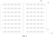
- some embodiments of the present disclosure provide a photovoltaic module, including solar cell strings 1 and electrode lines 12.
- the solar cell strings 1 each include solar cells 11 arranged in parallel.
- the electrode lines 12 are located on one sides of the solar cells 11 and configured to connect adjacent solar cells 11.
- soldering regions 111 are arranged on one sides of the solar cells 11 facing the electrode lines 12.
- the soldering regions 111 are arranged apart along a length direction X of the photovoltaic module.
- Connecting members 13 are arranged in the soldering regions 111, such that the electrode lines 12 are connected to the soldering regions 111 of the solar cells 11 through the connecting members 13.
- the connecting members 13 each include a first region 131 and a second region 132.
- the second region 132 is arranged around the first region 131, and transparency of the second region 132 is greater than that of the first region 131.
- the solar cell 11 provided in some embodiments of the present disclosure is a rear-back solar cell 11.
- a positive busbar and a negative busbar in the solar cell 11 are both located on a same side of the solar cell 11.
- the soldering region 111 is arranged on the positive busbar and the negative busbar of the solar cell 11.
- the electrode line 12 is configured to connect the positive busbars and the negative busbars between adjacent solar cells 11. Therefore, along a thickness direction Z of the photovoltaic module, the electrode lines 12 can be located on a same side of the adjacent solar cells 11.
- the positive busbar and the negative busbar of the rear-back solar cell 11 are both designed on a rear surface of the solar cell, and at the same time, a solder joint between a busbar and the electrode line 12 at an edge almost fit an edge of the solar cell 11. Therefore, there is a greater risk of problems such as cold soldering during the soldering.
- the arrangement of the connecting member 13 in the soldering region 111 can reduce a possibility of cold soldering between the electrode line 12 and the solar cell 11, helping to increase a yield of the photovoltaic module.
- Main components of the connecting member 13 are different metals such as tin-lead or tin-bismuth-silver, and organic solvents such as flux are also added to the connecting member 13 to facilitate soldering of the electrode line 12 and the solar cell 11.
- the connecting member 13 is heated and melted, and the organic solvents in the connecting member 13 may precipitate along a direction from the first region 131 to the second region 132. After the soldering, the precipitated organic solvents may gather at edges of the first region 131 in the connecting member 13 to form the second region 132. Due to greater transparency of the organic solvents, the transparency of the second region 132 is approximately 70% to 80% greater than the transparency of the first region 131.
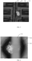
- the connecting member 13 after the electrode line 12 is connected to the soldering region 111, the connecting member 13 has a recessed portion 133 on a surface.
- Main components of the connecting member 13 are different metals such as tin-lead or tin-bismuth-silver, and organic solvents are also added to the connecting member 13 to facilitate soldering of the electrode line 12 and the solar cell 11.
- organic solvents When the connecting member 13 is heated, the organic solvents may volatilize by heat, and a recessed portion 133 may be formed on the surface of the connecting member 13. After the organic solvents volatilize, it is beneficial to improve strength of the soldering between the electrode line 12 and the solar cell 11.
- the electrode line 12 overlaps with the connecting member 13, and in projections along the thickness direction Z of the photovoltaic module, the projection of the recessed portion 133 on the solar cell 11 is located outside a projection region of the electrode line 12 on the solar cell 11.
- the projection of the recessed portion 133 on the solar cell 11 overlaps with the projection of the electrode line 12 on the solar cell 11, such that the recessed portion 133 also exists at a position where the electrode line 12 overlaps with the connecting member 13.
- the organic solvents in the connecting member 13 volatilize when the connecting member 13 is not completely cured, such that the connecting member 13 has the recessed portion 133 on the surface after curing.
- the organic solvents are evenly mixed with other components in the connecting member 13. Therefore, the recessed portion 133 formed due to the volatilization of the organic solvents may overlap with the electrode line 12 or may not overlap with the electrode line 12.
- the recessed portion 133 overlaps with the electrode line 12
- an area of contact between the electrode line 12 and the connecting member 13 may be reduced, so strength of the connection between the electrode line 12 and the connecting member 13 may be reduced. Therefore, in an ideal state, the projection of the recessed portion 133 is located outside the projection of the electrode line 12.
- the connecting member 13 has recessed portions 133 on the surface, and the recessed portions 133 are arranged apart.
- gaseous organic solvents may form bubbles on the surface of the connecting member 13. As the gaseous organic solvents in the bubbles gradually increase, the bubbles break to form recessed portions 133 on the surface of the connecting member 13. During the gasification of the organic solvents, adjacent organic solvents may gather into a bubble and then volatilize from the connecting member 13, such that the recessed portions 133 on the surface of the connecting member 13 are arranged apart.
- the connecting member 13 has recessed portions 133 on the surface, and adjacent recessed portions 133 are interconnected with each other.
- reaction is violent when the organic solvents volatilize, such that bubbles may be formed multiple times at a same position or similar positions on the surface of the connecting member 13. After breakage of the bubbles, recessed portions 133 interconnected with each other may be formed.
- the connecting member 13 includes a first region 131 and a second region 132, wherein the second region 132 is arranged around the first region 131. Both the first region 131 and the second region 132 are provided with the recessed portions 133, and an average size of the recessed portions 133 in the first region 131 is smaller than an average size of the recessed portions 133 in the second region 132.
- the organic solvents in the connecting member 13 When the connecting member 13 is heated, the organic solvents in the connecting member 13 have one part that may volatilize in the first region 131 and the other part that may flow from the first region 131 to the second region 132 and then volatilize in the second region 132, such that the organic solvents volatilizing in the first region 131 are smaller than the organic solvents volatilizing in the second region 132. Therefore, sizes of the recessed portions 133 in the first region 131 are smaller than sizes of the recessed portions 133 in the second region 132, and it is also possible that a number of the recessed portions 133 in the first region 131 is less than that of the recessed portions 133 in the second region 132.
- arrangement density of the recessed portions 133 in the second region 132 ranges from 3 ⁇ 10 3 pcs/mm 2 to 13 ⁇ 10 4 pcs/mm 2 .
- the arrangement density of the recessed portions 133 in the second region 132 may be 3 ⁇ 10 3 pcs/mm 2 , 13 ⁇ 10 3 pcs/mm 2 , 23 ⁇ 10 3 pcs/mm 2 , 33 ⁇ 10 3 pcs/mm 2 , 43 ⁇ 10 3 pcs/mm 2 , 53 ⁇ 10 3 pcs/mm 2 , 63 ⁇ 10 3 pcs/mm 2 , 73 ⁇ 10 3 pcs/mm 2 , 83 ⁇ 10 3 pcs/mm 2 , 93 ⁇ 10 3 pcs/mm 2 , 3 ⁇ 10 4 pcs/mm 2 , 13 ⁇ 10 4 pcs/mm 2 , or the like.
- the number of the recessed portions 133 in the second region 132 is less than 3 ⁇ 10 3 pcs/mm 2 , an effect of volatilization of the organic solvents may be reduced, resulting in residues of the organic solvents in the second region 132, thereby reducing reliability of the soldering between the electrode line 12 and the solar cell 11. If the number of the recessed portions 133 in the second region 132 is greater than 3 ⁇ 10 4 pcs/mm 2 , an area of contact between the connecting member 13 in the second region 132 and the electrode line 12 may be reduced, and strength of the connection between the second region 132 and the electrode line 12 may be reduced.
- the connecting member 13 further includes a third region 134, and the third region 134 is arranged around the second region 132.
- the organic solvents may precipitate along a direction from the first region 131 to the second region 132.
- part of the organic solvents may volatilize in the first region 131 and the second region 132, such that recessed portions 133 are formed in the first region 131 and the second region 132, and some non-volatilizing organic solvents may continue to precipitate to edges of the second region 132, forming a third region 134 around the second region 132.
- a width of the third region 134 is less than that of the second region 132.
- most of the organic solvents may volatilize in the first region 131 or the second region 132, and a small part of the organic solvents may form the third region 134. Therefore, the width of the third region 134 is less than that of the second region 132.
- the third region 134 is composed of non-volatilizing organic solvents. Therefore, the third region 134 includes no recessed portions 133 formed due to the volatilization of the organic solvents, arrangement density of the recessed portions 133 in the first region 131 may range from 100 pcs/mm 2 to 2000 pcs/mm 2 .
- the arrangement density of the recessed portions 133 in the first region 131 may be 100 pcs/mm 2 , 500 pcs/mm 2 , 1000 pcs/mm 2 , 1500 pcs/mm 2 , 2000 pcs/mm 2 , or the like.
- arrangement density of the recessed portions 133 in the third region 134 may range from 0 to 100 pcs/mm 2 .
- the arrangement density of the recessed portions 133 in the third region 134 may be 0, 20 pcs/mm 2 , 40 pcs/mm 2 , 60 pcs/mm 2 , 80 pcs/mm 2 , 100 pcs/mm 2 , or the like. Therefore, the third region 134 has higher flatness than the first region 131 and the second region 132.
- the organic solvents precipitate, main components are tin-lead, tin-bismuth-silver, or the like, and transparency thereof is less than that of the organic solvents.
- Transparency of the third region 134 is approximately 70% to 80%, which may be, for example, 70%, 75%, 80%, or the like.
- the first region 131 and the second region 132 are opaque or less transparent than the third region 134.
- the first region 131 has recessed portions 133 on the surface.
- the projection of the recessed portion 133 on the solar cell 11 is located outside a range of the projection of the electrode line 12 on the solar cell 11.
- the electrode line 12 is connected to the solar cell 11 through the connecting member 13. Therefore, the electrode line 12 has an overlapping portion with the first region 131. If the recessed portion 133 is arranged in the overlapping portion between the electrode line 12 and the first region 131, the area of contact between the electrode line 12 and the connecting member 13 may be reduced, resulting in a decrease in the strength of the connection between the electrode line 12 and the connecting member 13. If the recessed portion 133 in the first region 131 is outside an overlapping region between the electrode line 12 and the first region 131, an influence of the recessed portion 133 on the strength of the connection between the electrode line 12 and the connecting member 13 can be reduced.
- the width of the second region 132 is less than or equal to 30 ⁇ m.
- the recessed portion 133 is formed by the breakage of the bubbles formed by the gasification of the organic solvents in the connecting member 13. Therefore, in the projections along the thickness direction Z of the photovoltaic module, the projection of the recessed portion 133 in the solar cell 11 is in a shape of a circle or an ellipse.
- the recessed portion 133 may be hemispherical or cylindrical, which facilitates the organic solvents to volatilize from the connecting member 13, reducing the residues of the organic solvents in the connecting member 13, and helping to improve the reliability of the soldering between the electrode line 12 and the solar cell 11.
- the size of the recessed portion 133 ranges from 3 ⁇ m to 15 ⁇ m.
- the size of the recessed portion 133 may be 3 ⁇ m, 6 ⁇ m, 9 ⁇ m, 12 ⁇ m, 15 ⁇ m, or the like, which is 9 ⁇ m in some embodiments. If a width of the recessed portion 133 is less than 3 ⁇ m, an effect of volatilization of the organic solvents in the connecting member 13 may be reduced. If the width of the recessed portion 133 increases, it is easier for the organic solvents to volatilize.
- a width of the connecting member 13 ranges from 0.2 mm to 1 mm. If the width of the recessed portion 133 is greater than 15 ⁇ m, the recessed portion 133 accounts for a larger portion in the connecting member 13, which may affect the strength of the connection between the electrode line 12 and the connecting member 13.
- the organic solvents in the connecting member 13 have one part volatilizing in the first region 131 to form the recessed portions 133 and the other part precipitating from the first region 131 to form the second region 132.
- the arrangement density of the recessed portions 133 in the first region 131 may range from 100 pcs/mm 2 to 2000 pcs/mm 2 .
- the arrangement density of the recessed portions 133 in the first region 131 may be 100 pcs/mm 2 , 500 pcs/mm 2 , 1000 pcs/mm 2 , 1500 pcs/mm 2 , 2000 pcs/mm 2 , or the like.
- the arrangement density of the recessed portions 133 in the second region 132 may be 0, 20 pcs/mm 2 , 40 pcs/mm 2 , 60 pcs/mm 2 , 80 pcs/mm 2 , 100 pcs/mm 2 , or the like.
- the arrangement density of the recessed portions 133 in the second region 132 is lower. Therefore, the second region 134 has lower pore density and higher flatness.
- the first region 131 may be solder paste.
- the solder paste may improve capillarity and wettability, and reduce a possibility of cold soldering between the electrode line 12 and the solar cell 11.
- the solder paste may also isolate the air to prevent oxidation of solder joints between the electrode line 12 and the solar cell 11, helping to improve the reliability of the soldering between the electrode line 12 and the solar cell 11.
- the solar cells 11 arranged in parallel are connected into the solar cell string 1 through the electrode line 12, an upper surface and a lower surface of the solar cell string 1 are both provided with adhesive films, the upper surface of the solar cell string 1 is further provided with photovoltaic glass connected to the solar cell string 1 through the adhesive film, and the lower surface of the solar cell string 1 is further provided with photovoltaic glass or a back sheet which is also connected to the solar cell string 1 through the adhesive film to form the photovoltaic module.
- Some embodiments of the present disclosure further provide a manufacturing method for manufacturing a photovoltaic module for a photovoltaic module.
- the photovoltaic module includes solar cell strings 1, a back sheet, an adhesive film, and photovoltaic glass.
- the solar cell string 1 includes solar cells 11, a electrode line 12, and connecting members 13.
- the electrode line 12 is connected to the solar cells 11 through the connecting members 13.
- the method for manufacturing a photovoltaic module includes:
- the connecting member 13 is arranged between the electrode line 12 and the solar cell 11, which can improve the strength of the connection between the electrode line 12 and the solar cell 11 and reduce a possibility of cold soldering. Both the connecting member 13 and the electrode line 12 are placed on a surface of the solar cell 11, which omits the step of curing the connecting member 13 on the solar cell 11, helping to improve manufacturing efficiency of the solar cell string 1.
- the method for manufacturing a photovoltaic module includes: S11: printing the connecting members 13 in the soldering regions 111 of the solar cells 11.
- the connecting member 13 is arranged in the soldering region 111 by printing, which facilitates the control over a position and a shape of the connecting member 13, enabling the connecting member 13 to be located at a position where the electrode line 12 and the solar cell 11 are soldered.
- the connecting member 13 can reduce a possibility of colder soldering.
- the solar cell 11 includes a positive busbar and a negative busbar, the positive busbars and the negative busbars are alternately arranged on the solar cells 11 along a width direction Y of the photovoltaic module, and positions of the positive busbars and the negative busbars in the solar cells 11 are consistent. Therefore, when the solar cells 11 are placed on the operating platform 2, along a length direction X of the photovoltaic module, in adjacent solar cells 11, the positive busbars are located on a same straight line and the negative busbars are located on a same straight line.
- the method for manufacturing a photovoltaic module includes: S21: rotating one of two adjacent solar cells 11 by 180° such that, in the adjacent solar cells 11, the positive busbar of one and the negative busbar of the other are located on a same straight line along the length direction X of the photovoltaic module.
- the electrode line 12 is configured to connect the positive busbars and the negative busbars in the adjacent solar cells 11, and in the adjacent solar cells 11, the positive busbar of one and the negative busbar of the other are located on a same straight line, such that the electrode line 12 can be arranged on one side of the solar cell 11 provided with the positive busbar and the negative busbar.
- the method for manufacturing a photovoltaic module includes: S31: fixing the electrode lines 12 to the sides of the solar cells 11 provided with the connecting members 13.
- a force is applied to the electrode line 12 on a side of the electrode line 12 away from the solar cell 11 to fix the electrode line 12 to the solar cell 11, which reduces a possibility of displacement of the electrode line 12 during subsequent soldering between the electrode line 12 and the solar cell 11, helping to increase a yield of the solar cell string 1.
- the operating platform 2 for placing the solar cell 11 can heat the solar cell 11 and then solder the solar cell 11 and the electrode line 12.
- the method for manufacturing a photovoltaic module includes: a heating temperature ranging from 130°C to 220°C, and heating time ranging from 1.5 s to 6 s.
- the solar cell 11 transfers heat emitted by a heating platform to the connecting member 13 and the electrode line 12, causing the connecting member 13 to melt to connect the electrode line 12 and the solar cell 11.
- the heating temperature may be 130°C, 150°C, 170°C, 190°C, 210°C, 220°C, or the like, and the heating time may be 1.5 s, 2.5 s, 3.5 s, 4.5 s, 5.5 s, 6 s, or the like.
- the organic solvents in the connecting member 13 have one part volatilizing in the first region 131 to form recessed portions 133 and the other part precipitating from the first region 131 to form the second region 132.
- a heating apparatus is arranged on one side of the solar cell 11 away from the operating platform 2.
- the heating apparatus may be an infrared lamp box.
- the electrode line 12 and the connecting member 13 are heated by the heating apparatus, thereby soldering the solar cell 11 and the electrode line 12.
- the method for manufacturing a photovoltaic module includes: a heating temperature ranging from 230°C to 240°C, and heating time being less than or equal to 5 s.
- the heating temperature may be 230°C, 235°C, 240°C, or the like.
- the solar cell 11 is not required to transfer heat, and at the same time, the infrared heating apparatus can provide a higher temperature. Therefore, the soldering between the electrode line 12 and the solar cell 11 can be completed when the heating time is less than or equal to 5 s.
- the method for manufacturing a photovoltaic module includes: fixing the connecting members 13 to the solar cells 11 by heating.
- the connecting member 13 is first fixed to the solar cell 11 by heating, which limits a relative position between the connecting member 13 and the solar cell 11. In the step of soldering the electrode line 12 and the solar cell 11 through the connecting member 13, a possibility of displacement of the connecting member 13 is reduced, and a possibility of colder soldering between the electrode line 12 and the solar cell 11 is reduced.
- the connecting member 13 may be solder paste.
- the method for manufacturing a photovoltaic module includes: S21: heating the solder paste to 120°C to 180°C for 10 s to 60 s.
- the solar cell 11 printed with the solder paste is placed in a curing furnace for heating.
- a heating temperature may be 120°C, 130°C, 140°C, 150°C, 160°C, 170°C, 180°C, or the like, and heating time may be 10 s, 20 s, 30 s, 40 s, 50 s, 60 s, or the like.
- the solder paste is cured and fixed to the solar cell 11.
- the solder paste includes organic solvents such as flux.
- the organic solvents such as flux in the solder paste may volatilize or precipitate from a center of the solder paste to edges, which reduces content of the organic solvents in the solder paste and can improve strength of the soldering between the electrode line 12 and the solar cell 11.
- Some embodiments of the present disclosure further provide a machining device, for manufacturing a photovoltaic module.
- the machining device includes an operating platform 2, pressing tools 3, and a heating apparatus.
- the pressing tool 3 is mounted on the operating platform 2 and configured to limit positions of solar cells 11 and electrode lines 12 in the photovoltaic module.
- the heating apparatus is configured to heat connecting members 13 and the electrode lines 12.
- the solar cell 11 is placed on the operating platform 2.
- One side of the solar cell 11 provided with no positive busbar and no negative busbar faces the operating platform 2.
- the pressing tool 3 includes a bracket 31 and abutting members 32.
- the bracket 31 is configured to fix positions of the abutting members 32, such that the abutting members 32 are located above the electrode line 12.
- the abutting members 32 are connected to the bracket 31 through an elastic member 33.
- An elastic force of the elastic member 33 may be transferred to the electrode line 12 through the abutting members 32, such that the electrode line 12 is fixed to the solar cells 11, facilitating heating of the solar cells 11, the connecting members 13, and the electrode line 12 to form the solar cell string 1.
- the heating apparatus is located in the operating platform 2, the solar cell 11 can be placed on a surface of the heating apparatus, and the solar cell 11 is heated through the heating apparatus to melt the connecting member 13 and then connect the electrode line 12 and the solar cell 11.
- one side of the solar cell 11 provided with the busbars can be heated, heat is transferred, through the solar cell 11, to the side of the solar cell 11 provided with the busbars to heat the connecting member 13 and the electrode line 12, and then the electrode line 12 and the solar cell 11 can be connected.
- the heating apparatus is a curing furnace, a heating member is arranged in the curing furnace, the solar cell 11 can enter the curing furnace along with the operating platform 2, the heating member is located on one side of the solar cell 11 where the connecting member 13 and the electrode line 12 are placed, and the solar cell 11, the connecting member 13, and the electrode line 12 are heated through the heating member, to connect the electrode line 12 and the solar cell 11.
- the heating member may be an infrared heating apparatus, and the connecting member 13 and the electrode line 12 can be directly heated through the infrared heating apparatus. At the same time, a heating temperature of the infrared heating apparatus is higher, such that the connecting member 13 can melt more easily and then connect the electrode line 12 and the solar cell 11.
- the pressing tool 3 includes a bracket 31 and abutting members 32.
- the bracket 31 is configured to fix positions of the abutting members 32.
- the abutting members 32 are configured to provide forces for the electrode line 12.
- the abutting members 32 are connected to the bracket 31 through an elastic member 33.
- An elastic force of the elastic member 33 may be transferred to the electrode line 12 through the abutting members 32, such that the electrode line 12 is fixed to the solar cells 11.
- the machining device further includes a heating apparatus and a soldering apparatus.
- the heating apparatus and the soldering apparatus are located upstream of the operating platform and downstream of the operating platform respectively.
- the heating apparatus is entered first, the connecting members are cured, and the connecting members are fixed to the solar cells.
- the solar cells are placed on the operating platform, and relative positions of the electrode lines and the solar cells are limited through the pressing tools, which are finally placed in the soldering apparatus to solder the electrode lines and the solar cells.
- Some embodiments of the present disclosure provide a photovoltaic module, a manufacturing method for manufacturing a photovoltaic module for a photovoltaic module, and a machining device.
- the photovoltaic module includes solar cell strings 1 and electrode lines 12.
- the solar cell string 1 includes solar cells 11 arranged in parallel, and the electrode line 12 is located on one sides of the solar cells 11 and configured to connect adjacent solar cells 11 to form the solar cell string 1.
- soldering regions 111 are arranged apart on the solar cell 11 along a length direction X of the photovoltaic module, connecting members 13 are arranged in the soldering regions 111, the electrode line 12 is located on one sides of the solar cells 11 provided with the connecting members 13, and the connecting members 13 can reduce a possibility of cold soldering between the electrode line 12 and the solar cells 11, helping to increase a yield of the solar cell string 1.
- the connecting member 13 includes a first region 131 and a second region 132.
- the second region 132 is arranged around the first region 131, and transparency of the second region 132 is greater than that of the first region 131.
Landscapes
- Photovoltaic Devices (AREA)
Applications Claiming Priority (2)
| Application Number | Priority Date | Filing Date | Title |
|---|---|---|---|
| CN202310610355.1A CN116404061A (zh) | 2023-05-26 | 2023-05-26 | 一种光伏组件、光伏组件的制作方法及加工设备 |
| CN202310609235.XA CN116487463B (zh) | 2023-05-26 | 2023-05-26 | 一种光伏组件及光伏组件的制作方法 |
Publications (2)
| Publication Number | Publication Date |
|---|---|
| EP4468372A2 true EP4468372A2 (de) | 2024-11-27 |
| EP4468372A3 EP4468372A3 (de) | 2024-12-18 |
Family
ID=87519920
Family Applications (1)
| Application Number | Title | Priority Date | Filing Date |
|---|---|---|---|
| EP23188341.4A Pending EP4468372A3 (de) | 2023-05-26 | 2023-07-28 | Fotovoltaisches modul, herstellungsverfahren für fotovoltaisches modul und bearbeitungsvorrichtung |
Country Status (4)
| Country | Link |
|---|---|
| US (1) | US20240395957A1 (de) |
| EP (1) | EP4468372A3 (de) |
| JP (1) | JP7592130B1 (de) |
| AU (1) | AU2023219797B2 (de) |
Family Cites Families (13)
| Publication number | Priority date | Publication date | Assignee | Title |
|---|---|---|---|---|
| JP2002263880A (ja) * | 2001-03-06 | 2002-09-17 | Hitachi Cable Ltd | Pbフリー半田、およびこれを使用した接続用リード線ならびに電気部品 |
| JP5159725B2 (ja) * | 2009-08-27 | 2013-03-13 | 三洋電機株式会社 | 太陽電池ストリング及びそれを用いた太陽電池モジュール |
| DE102010017180A1 (de) * | 2010-06-01 | 2011-12-01 | Solarworld Innovations Gmbh | Solarzelle, Solarmodul, und Verfahren zum Verdrahten einer Solarzelle, und Kontaktdraht |
| JP5231515B2 (ja) * | 2010-12-17 | 2013-07-10 | シャープ株式会社 | 太陽電池の製造方法 |
| US8859322B2 (en) * | 2012-03-19 | 2014-10-14 | Rec Solar Pte. Ltd. | Cell and module processing of semiconductor wafers for back-contacted solar photovoltaic module |
| CN102751361A (zh) | 2012-07-25 | 2012-10-24 | 合肥海润光伏科技有限公司 | 背接触太阳能电池串及其制作方法 |
| CN103203557A (zh) | 2013-01-29 | 2013-07-17 | 太仓海润太阳能有限公司 | 一种背接触太阳能电池组件的焊接方法 |
| KR20160076393A (ko) * | 2014-12-22 | 2016-06-30 | 엘지전자 주식회사 | 태양 전지 모듈 |
| KR102622743B1 (ko) * | 2017-02-13 | 2024-01-10 | 상라오 신위안 웨동 테크놀러지 디벨롭먼트 컴퍼니, 리미티드 | 태양전지 및 태양전지 모듈 |
| KR101941237B1 (ko) * | 2017-09-13 | 2019-01-23 | 한국에너지기술연구원 | 태양 전지 셀 어레이, 태양 전지 모듈, 그리고 이의 제조 방법 |
| CN111785804A (zh) | 2020-05-27 | 2020-10-16 | 泰州隆基乐叶光伏科技有限公司 | 一种背接触电池组件生产方法及系统 |
| CN115117206B (zh) * | 2022-08-30 | 2022-12-16 | 苏州小牛自动化设备有限公司 | 一种光伏组件的制造方法及电池模块、电池串与光伏组件 |
| CN115732580A (zh) * | 2022-12-12 | 2023-03-03 | 浙江晶科能源有限公司 | 光伏组件 |
-
2023
- 2023-07-27 JP JP2023122880A patent/JP7592130B1/ja active Active
- 2023-07-28 EP EP23188341.4A patent/EP4468372A3/de active Pending
- 2023-07-31 US US18/362,944 patent/US20240395957A1/en active Pending
- 2023-08-21 AU AU2023219797A patent/AU2023219797B2/en active Active
Also Published As
| Publication number | Publication date |
|---|---|
| EP4468372A3 (de) | 2024-12-18 |
| AU2023219797B2 (en) | 2025-08-28 |
| AU2023219797A1 (en) | 2024-12-12 |
| JP2024170273A (ja) | 2024-12-06 |
| US20240395957A1 (en) | 2024-11-28 |
| JP7592130B1 (ja) | 2024-11-29 |
Similar Documents
| Publication | Publication Date | Title |
|---|---|---|
| CN107078174B (zh) | 太阳能电池互连件 | |
| EP2216827A1 (de) | Solarbatteriemodul und verfahren zur herstellung eines solarbatteriemoduls | |
| WO2024108996A1 (zh) | 分段低温焊带、无主栅ibc电池串、电池组件及其封装方法 | |
| EP2528104A1 (de) | Solarzelle mit rückseitenkontakten, verdrahtungsplatte, solarzelle mit der verdrahtungsplatte, solarzellenmodul und herstellungsverfahren für eine solarzelle mit der verdrahtungsplatte | |
| CN112201720B (zh) | 太阳能电池组件制备方法及太阳能电池组件 | |
| KR20080100373A (ko) | 광전지 셀들을 결합하는 방법 및 이를 구현하기 위한 막 | |
| JP2011151334A (ja) | 太陽電池モジュールの製造方法 | |
| CN115224161B (zh) | 一种新型无主栅太阳能光伏组件的制作方法 | |
| CN116487463A (zh) | 一种光伏组件、光伏组件的制作方法及加工设备 | |
| CN116404061A (zh) | 一种光伏组件、光伏组件的制作方法及加工设备 | |
| CN114512573A (zh) | 一种用于光伏行业电池片无应力焊接设备的焊接工艺 | |
| EP4468372A2 (de) | Fotovoltaisches modul, herstellungsverfahren für fotovoltaisches modul und bearbeitungsvorrichtung | |
| CN101937936B (zh) | 一种太阳能电池组件 | |
| JP5100629B2 (ja) | 太陽電池モジュールの製造方法 | |
| CN110010707A (zh) | 双面受光型太阳能电池模块 | |
| CN207852701U (zh) | 配线片 | |
| JP5193605B2 (ja) | 光電池パネル | |
| CN220628165U (zh) | Fpc采集装置及电池模组 | |
| CN116190480A (zh) | 一种光伏单元、光伏组件及其制备方法 | |
| EP3762974B1 (de) | Vorrichtung und verfahren zur herstellung einer solarzellenanordnung | |
| CN222448900U (zh) | 红外加热设备及焊接装置 | |
| CN117637906A (zh) | 电池串制备方法、光伏组件及其制备方法 | |
| CN117637907A (zh) | 电池串制备方法、光伏组件及其制备方法 | |
| EP4598308A1 (de) | Solarzellenstring und solarzellenmodul | |
| CN208596690U (zh) | 一种汇流条及太阳能电池板 |
Legal Events
| Date | Code | Title | Description |
|---|---|---|---|
| PUAI | Public reference made under article 153(3) epc to a published international application that has entered the european phase |
Free format text: ORIGINAL CODE: 0009012 |
|
| STAA | Information on the status of an ep patent application or granted ep patent |
Free format text: STATUS: REQUEST FOR EXAMINATION WAS MADE |
|
| PUAL | Search report despatched |
Free format text: ORIGINAL CODE: 0009013 |
|
| 17P | Request for examination filed |
Effective date: 20230728 |
|
| AK | Designated contracting states |
Kind code of ref document: A2 Designated state(s): AL AT BE BG CH CY CZ DE DK EE ES FI FR GB GR HR HU IE IS IT LI LT LU LV MC ME MK MT NL NO PL PT RO RS SE SI SK SM TR |
|
| AK | Designated contracting states |
Kind code of ref document: A3 Designated state(s): AL AT BE BG CH CY CZ DE DK EE ES FI FR GB GR HR HU IE IS IT LI LT LU LV MC ME MK MT NL NO PL PT RO RS SE SI SK SM TR |
|
| RIC1 | Information provided on ipc code assigned before grant |
Ipc: H01L 31/05 20140101ALI20241113BHEP Ipc: H01L 31/048 20140101ALI20241113BHEP Ipc: H01L 31/0224 20060101AFI20241113BHEP |
|
| STAA | Information on the status of an ep patent application or granted ep patent |
Free format text: STATUS: EXAMINATION IS IN PROGRESS |
|
| 17Q | First examination report despatched |
Effective date: 20250801 |
|
| REG | Reference to a national code |
Ref country code: DE Ref legal event code: R079 Free format text: PREVIOUS MAIN CLASS: H01L0031022400 Ipc: H10F0077200000 |
|
| GRAP | Despatch of communication of intention to grant a patent |
Free format text: ORIGINAL CODE: EPIDOSNIGR1 |
|
| STAA | Information on the status of an ep patent application or granted ep patent |
Free format text: STATUS: GRANT OF PATENT IS INTENDED |
|
| RIC1 | Information provided on ipc code assigned before grant |
Ipc: H10F 77/20 20250101AFI20260224BHEP Ipc: H10F 19/80 20250101ALI20260224BHEP Ipc: H10F 19/90 20250101ALI20260224BHEP |
|
| INTG | Intention to grant announced |
Effective date: 20260311 |
|
| RIN1 | Information on inventor provided before grant (corrected) |
Inventor name: TAO, WUSONG Inventor name: WANG, LUCHUANG Inventor name: QIN, NIANNIAN |