EP4465415A1 - Wärmeleitendes material, verfahren zur herstellung des wärmeleitenden materials und batteriemodul - Google Patents
Wärmeleitendes material, verfahren zur herstellung des wärmeleitenden materials und batteriemodul Download PDFInfo
- Publication number
- EP4465415A1 EP4465415A1 EP24173789.9A EP24173789A EP4465415A1 EP 4465415 A1 EP4465415 A1 EP 4465415A1 EP 24173789 A EP24173789 A EP 24173789A EP 4465415 A1 EP4465415 A1 EP 4465415A1
- Authority
- EP
- European Patent Office
- Prior art keywords
- filler
- conductive material
- heat conductive
- heat
- material according
- Prior art date
- Legal status (The legal status is an assumption and is not a legal conclusion. Google has not performed a legal analysis and makes no representation as to the accuracy of the status listed.)
- Pending
Links
- 239000004020 conductor Substances 0.000 title claims abstract description 128
- 238000004519 manufacturing process Methods 0.000 title claims description 9
- 239000000945 filler Substances 0.000 claims abstract description 262
- 229920005989 resin Polymers 0.000 claims abstract description 84
- 239000011347 resin Substances 0.000 claims abstract description 84
- 230000005291 magnetic effect Effects 0.000 claims abstract description 68
- 239000011159 matrix material Substances 0.000 claims abstract description 34
- 239000000463 material Substances 0.000 claims description 34
- 229920001187 thermosetting polymer Polymers 0.000 claims description 25
- PZNSFCLAULLKQX-UHFFFAOYSA-N Boron nitride Chemical group N#B PZNSFCLAULLKQX-UHFFFAOYSA-N 0.000 claims description 19
- 239000002243 precursor Substances 0.000 claims description 19
- 229920002050 silicone resin Polymers 0.000 claims description 18
- 229910052582 BN Inorganic materials 0.000 claims description 15
- 230000015556 catabolic process Effects 0.000 claims description 15
- 239000003822 epoxy resin Substances 0.000 claims description 11
- 238000000034 method Methods 0.000 claims description 11
- 229920000647 polyepoxide Polymers 0.000 claims description 11
- LTPBRCUWZOMYOC-UHFFFAOYSA-N Beryllium oxide Chemical compound O=[Be] LTPBRCUWZOMYOC-UHFFFAOYSA-N 0.000 claims description 10
- 229910052751 metal Inorganic materials 0.000 claims description 9
- 239000002184 metal Substances 0.000 claims description 9
- CPLXHLVBOLITMK-UHFFFAOYSA-N Magnesium oxide Chemical compound [Mg]=O CPLXHLVBOLITMK-UHFFFAOYSA-N 0.000 claims description 7
- 239000011342 resin composition Substances 0.000 claims description 7
- OKTJSMMVPCPJKN-UHFFFAOYSA-N Carbon Chemical group [C] OKTJSMMVPCPJKN-UHFFFAOYSA-N 0.000 claims description 6
- 229910044991 metal oxide Inorganic materials 0.000 claims description 6
- 150000004706 metal oxides Chemical class 0.000 claims description 6
- 229910052581 Si3N4 Inorganic materials 0.000 claims description 5
- HQVNEWCFYHHQES-UHFFFAOYSA-N silicon nitride Chemical compound N12[Si]34N5[Si]62N3[Si]51N64 HQVNEWCFYHHQES-UHFFFAOYSA-N 0.000 claims description 5
- PNEYBMLMFCGWSK-UHFFFAOYSA-N aluminium oxide Inorganic materials [O-2].[O-2].[O-2].[Al+3].[Al+3] PNEYBMLMFCGWSK-UHFFFAOYSA-N 0.000 claims description 4
- 229910052799 carbon Inorganic materials 0.000 claims description 4
- 239000000395 magnesium oxide Substances 0.000 claims description 3
- PMHQVHHXPFUNSP-UHFFFAOYSA-M copper(1+);methylsulfanylmethane;bromide Chemical compound Br[Cu].CSC PMHQVHHXPFUNSP-UHFFFAOYSA-M 0.000 claims description 2
- 238000009413 insulation Methods 0.000 abstract description 26
- 230000000052 comparative effect Effects 0.000 description 20
- 239000010410 layer Substances 0.000 description 17
- 230000004043 responsiveness Effects 0.000 description 16
- 239000003795 chemical substances by application Substances 0.000 description 11
- PXHVJJICTQNCMI-UHFFFAOYSA-N Nickel Chemical compound [Ni] PXHVJJICTQNCMI-UHFFFAOYSA-N 0.000 description 8
- 239000002245 particle Substances 0.000 description 8
- 229920000049 Carbon (fiber) Polymers 0.000 description 6
- 239000004917 carbon fiber Substances 0.000 description 6
- VNWKTOKETHGBQD-UHFFFAOYSA-N methane Chemical compound C VNWKTOKETHGBQD-UHFFFAOYSA-N 0.000 description 6
- 239000000835 fiber Substances 0.000 description 5
- 230000005855 radiation Effects 0.000 description 5
- 230000005865 ionizing radiation Effects 0.000 description 4
- 229910052759 nickel Inorganic materials 0.000 description 4
- 239000000843 powder Substances 0.000 description 4
- 239000011231 conductive filler Substances 0.000 description 3
- 230000000694 effects Effects 0.000 description 3
- TWNQGVIAIRXVLR-UHFFFAOYSA-N oxo(oxoalumanyloxy)alumane Chemical compound O=[Al]O[Al]=O TWNQGVIAIRXVLR-UHFFFAOYSA-N 0.000 description 3
- XEEYBQQBJWHFJM-UHFFFAOYSA-N Iron Chemical compound [Fe] XEEYBQQBJWHFJM-UHFFFAOYSA-N 0.000 description 2
- UQSXHKLRYXJYBZ-UHFFFAOYSA-N Iron oxide Chemical compound [Fe]=O UQSXHKLRYXJYBZ-UHFFFAOYSA-N 0.000 description 2
- -1 acryl Chemical group 0.000 description 2
- 239000011247 coating layer Substances 0.000 description 2
- 238000004891 communication Methods 0.000 description 2
- 239000002889 diamagnetic material Substances 0.000 description 2
- 230000004907 flux Effects 0.000 description 2
- 229910002804 graphite Inorganic materials 0.000 description 2
- 239000010439 graphite Substances 0.000 description 2
- 230000020169 heat generation Effects 0.000 description 2
- 239000011256 inorganic filler Substances 0.000 description 2
- 229910003475 inorganic filler Inorganic materials 0.000 description 2
- 239000007788 liquid Substances 0.000 description 2
- 238000005259 measurement Methods 0.000 description 2
- 238000002156 mixing Methods 0.000 description 2
- 239000002907 paramagnetic material Substances 0.000 description 2
- 239000004065 semiconductor Substances 0.000 description 2
- PIGFYZPCRLYGLF-UHFFFAOYSA-N Aluminum nitride Chemical compound [Al]#N PIGFYZPCRLYGLF-UHFFFAOYSA-N 0.000 description 1
- CIWBSHSKHKDKBQ-JLAZNSOCSA-N Ascorbic acid Chemical compound OC[C@H](O)[C@H]1OC(=O)C(O)=C1O CIWBSHSKHKDKBQ-JLAZNSOCSA-N 0.000 description 1
- 239000004593 Epoxy Substances 0.000 description 1
- JOYRKODLDBILNP-UHFFFAOYSA-N Ethyl urethane Chemical compound CCOC(N)=O JOYRKODLDBILNP-UHFFFAOYSA-N 0.000 description 1
- 239000004952 Polyamide Substances 0.000 description 1
- 239000006087 Silane Coupling Agent Substances 0.000 description 1
- RTAQQCXQSZGOHL-UHFFFAOYSA-N Titanium Chemical compound [Ti] RTAQQCXQSZGOHL-UHFFFAOYSA-N 0.000 description 1
- HCHKCACWOHOZIP-UHFFFAOYSA-N Zinc Chemical compound [Zn] HCHKCACWOHOZIP-UHFFFAOYSA-N 0.000 description 1
- 239000002253 acid Substances 0.000 description 1
- 125000002723 alicyclic group Chemical group 0.000 description 1
- 125000001931 aliphatic group Chemical group 0.000 description 1
- 229920000180 alkyd Polymers 0.000 description 1
- 229910052782 aluminium Inorganic materials 0.000 description 1
- XAGFODPZIPBFFR-UHFFFAOYSA-N aluminium Chemical compound [Al] XAGFODPZIPBFFR-UHFFFAOYSA-N 0.000 description 1
- 150000001412 amines Chemical class 0.000 description 1
- 229910052925 anhydrite Inorganic materials 0.000 description 1
- IISBACLAFKSPIT-UHFFFAOYSA-N bisphenol A Chemical compound C=1C=C(O)C=CC=1C(C)(C)C1=CC=C(O)C=C1 IISBACLAFKSPIT-UHFFFAOYSA-N 0.000 description 1
- OSGAYBCDTDRGGQ-UHFFFAOYSA-L calcium sulfate Chemical compound [Ca+2].[O-]S([O-])(=O)=O OSGAYBCDTDRGGQ-UHFFFAOYSA-L 0.000 description 1
- 239000003054 catalyst Substances 0.000 description 1
- 125000003636 chemical group Chemical group 0.000 description 1
- 238000006243 chemical reaction Methods 0.000 description 1
- 239000011248 coating agent Substances 0.000 description 1
- 238000000576 coating method Methods 0.000 description 1
- 229910017052 cobalt Inorganic materials 0.000 description 1
- 239000010941 cobalt Substances 0.000 description 1
- GUTLYIVDDKVIGB-UHFFFAOYSA-N cobalt atom Chemical compound [Co] GUTLYIVDDKVIGB-UHFFFAOYSA-N 0.000 description 1
- 238000001816 cooling Methods 0.000 description 1
- QDOXWKRWXJOMAK-UHFFFAOYSA-N dichromium trioxide Chemical compound O=[Cr]O[Cr]=O QDOXWKRWXJOMAK-UHFFFAOYSA-N 0.000 description 1
- 239000003792 electrolyte Substances 0.000 description 1
- 238000011156 evaluation Methods 0.000 description 1
- 239000003302 ferromagnetic material Substances 0.000 description 1
- 238000010438 heat treatment Methods 0.000 description 1
- 230000010365 information processing Effects 0.000 description 1
- 239000011810 insulating material Substances 0.000 description 1
- 229910052742 iron Inorganic materials 0.000 description 1
- 230000001678 irradiating effect Effects 0.000 description 1
- 125000002496 methyl group Chemical group [H]C([H])([H])* 0.000 description 1
- LAQFLZHBVPULPL-UHFFFAOYSA-N methyl(phenyl)silicon Chemical compound C[Si]C1=CC=CC=C1 LAQFLZHBVPULPL-UHFFFAOYSA-N 0.000 description 1
- 239000000203 mixture Substances 0.000 description 1
- 229920003986 novolac Polymers 0.000 description 1
- 230000003287 optical effect Effects 0.000 description 1
- AFEQENGXSMURHA-UHFFFAOYSA-N oxiran-2-ylmethanamine Chemical compound NCC1CO1 AFEQENGXSMURHA-UHFFFAOYSA-N 0.000 description 1
- 125000001997 phenyl group Chemical group [H]C1=C([H])C([H])=C(*)C([H])=C1[H] 0.000 description 1
- 229920002647 polyamide Polymers 0.000 description 1
- 229920000728 polyester Polymers 0.000 description 1
- 229920000642 polymer Polymers 0.000 description 1
- 230000002195 synergetic effect Effects 0.000 description 1
- 229910052725 zinc Inorganic materials 0.000 description 1
- 239000011701 zinc Substances 0.000 description 1
- 229910000859 α-Fe Inorganic materials 0.000 description 1
Images

Classifications
-
- C—CHEMISTRY; METALLURGY
- C08—ORGANIC MACROMOLECULAR COMPOUNDS; THEIR PREPARATION OR CHEMICAL WORKING-UP; COMPOSITIONS BASED THEREON
- C08K—Use of inorganic or non-macromolecular organic substances as compounding ingredients
- C08K7/00—Use of ingredients characterised by shape
- C08K7/02—Fibres or whiskers
- C08K7/04—Fibres or whiskers inorganic
- C08K7/06—Elements
-
- C—CHEMISTRY; METALLURGY
- C08—ORGANIC MACROMOLECULAR COMPOUNDS; THEIR PREPARATION OR CHEMICAL WORKING-UP; COMPOSITIONS BASED THEREON
- C08K—Use of inorganic or non-macromolecular organic substances as compounding ingredients
- C08K3/00—Use of inorganic substances as compounding ingredients
- C08K3/01—Use of inorganic substances as compounding ingredients characterized by their specific function
- C08K3/013—Fillers, pigments or reinforcing additives
-
- C—CHEMISTRY; METALLURGY
- C08—ORGANIC MACROMOLECULAR COMPOUNDS; THEIR PREPARATION OR CHEMICAL WORKING-UP; COMPOSITIONS BASED THEREON
- C08K—Use of inorganic or non-macromolecular organic substances as compounding ingredients
- C08K3/00—Use of inorganic substances as compounding ingredients
- C08K3/02—Elements
- C08K3/04—Carbon
-
- C—CHEMISTRY; METALLURGY
- C08—ORGANIC MACROMOLECULAR COMPOUNDS; THEIR PREPARATION OR CHEMICAL WORKING-UP; COMPOSITIONS BASED THEREON
- C08K—Use of inorganic or non-macromolecular organic substances as compounding ingredients
- C08K3/00—Use of inorganic substances as compounding ingredients
- C08K3/02—Elements
- C08K3/08—Metals
-
- C—CHEMISTRY; METALLURGY
- C08—ORGANIC MACROMOLECULAR COMPOUNDS; THEIR PREPARATION OR CHEMICAL WORKING-UP; COMPOSITIONS BASED THEREON
- C08K—Use of inorganic or non-macromolecular organic substances as compounding ingredients
- C08K3/00—Use of inorganic substances as compounding ingredients
- C08K3/18—Oxygen-containing compounds, e.g. metal carbonyls
- C08K3/20—Oxides; Hydroxides
- C08K3/22—Oxides; Hydroxides of metals
-
- C—CHEMISTRY; METALLURGY
- C08—ORGANIC MACROMOLECULAR COMPOUNDS; THEIR PREPARATION OR CHEMICAL WORKING-UP; COMPOSITIONS BASED THEREON
- C08K—Use of inorganic or non-macromolecular organic substances as compounding ingredients
- C08K3/00—Use of inorganic substances as compounding ingredients
- C08K3/28—Nitrogen-containing compounds
-
- C—CHEMISTRY; METALLURGY
- C08—ORGANIC MACROMOLECULAR COMPOUNDS; THEIR PREPARATION OR CHEMICAL WORKING-UP; COMPOSITIONS BASED THEREON
- C08K—Use of inorganic or non-macromolecular organic substances as compounding ingredients
- C08K3/00—Use of inorganic substances as compounding ingredients
- C08K3/34—Silicon-containing compounds
-
- C—CHEMISTRY; METALLURGY
- C08—ORGANIC MACROMOLECULAR COMPOUNDS; THEIR PREPARATION OR CHEMICAL WORKING-UP; COMPOSITIONS BASED THEREON
- C08K—Use of inorganic or non-macromolecular organic substances as compounding ingredients
- C08K3/00—Use of inorganic substances as compounding ingredients
- C08K3/38—Boron-containing compounds
-
- C—CHEMISTRY; METALLURGY
- C08—ORGANIC MACROMOLECULAR COMPOUNDS; THEIR PREPARATION OR CHEMICAL WORKING-UP; COMPOSITIONS BASED THEREON
- C08K—Use of inorganic or non-macromolecular organic substances as compounding ingredients
- C08K7/00—Use of ingredients characterised by shape
-
- C—CHEMISTRY; METALLURGY
- C08—ORGANIC MACROMOLECULAR COMPOUNDS; THEIR PREPARATION OR CHEMICAL WORKING-UP; COMPOSITIONS BASED THEREON
- C08L—COMPOSITIONS OF MACROMOLECULAR COMPOUNDS
- C08L63/00—Compositions of epoxy resins; Compositions of derivatives of epoxy resins
-
- C—CHEMISTRY; METALLURGY
- C08—ORGANIC MACROMOLECULAR COMPOUNDS; THEIR PREPARATION OR CHEMICAL WORKING-UP; COMPOSITIONS BASED THEREON
- C08L—COMPOSITIONS OF MACROMOLECULAR COMPOUNDS
- C08L83/00—Compositions of macromolecular compounds obtained by reactions forming in the main chain of the macromolecule a linkage containing silicon with or without sulfur, nitrogen, oxygen or carbon only; Compositions of derivatives of such polymers
- C08L83/04—Polysiloxanes
-
- C—CHEMISTRY; METALLURGY
- C09—DYES; PAINTS; POLISHES; NATURAL RESINS; ADHESIVES; COMPOSITIONS NOT OTHERWISE PROVIDED FOR; APPLICATIONS OF MATERIALS NOT OTHERWISE PROVIDED FOR
- C09D—COATING COMPOSITIONS, e.g. PAINTS, VARNISHES OR LACQUERS; FILLING PASTES; CHEMICAL PAINT OR INK REMOVERS; INKS; CORRECTING FLUIDS; WOODSTAINS; PASTES OR SOLIDS FOR COLOURING OR PRINTING; USE OF MATERIALS THEREFOR
- C09D183/00—Coating compositions based on macromolecular compounds obtained by reactions forming in the main chain of the macromolecule a linkage containing silicon, with or without sulfur, nitrogen, oxygen, or carbon only; Coating compositions based on derivatives of such polymers
- C09D183/04—Polysiloxanes
-
- C—CHEMISTRY; METALLURGY
- C09—DYES; PAINTS; POLISHES; NATURAL RESINS; ADHESIVES; COMPOSITIONS NOT OTHERWISE PROVIDED FOR; APPLICATIONS OF MATERIALS NOT OTHERWISE PROVIDED FOR
- C09D—COATING COMPOSITIONS, e.g. PAINTS, VARNISHES OR LACQUERS; FILLING PASTES; CHEMICAL PAINT OR INK REMOVERS; INKS; CORRECTING FLUIDS; WOODSTAINS; PASTES OR SOLIDS FOR COLOURING OR PRINTING; USE OF MATERIALS THEREFOR
- C09D5/00—Coating compositions, e.g. paints, varnishes or lacquers, characterised by their physical nature or the effects produced; Filling pastes
- C09D5/18—Fireproof paints including high temperature resistant paints
-
- C—CHEMISTRY; METALLURGY
- C09—DYES; PAINTS; POLISHES; NATURAL RESINS; ADHESIVES; COMPOSITIONS NOT OTHERWISE PROVIDED FOR; APPLICATIONS OF MATERIALS NOT OTHERWISE PROVIDED FOR
- C09D—COATING COMPOSITIONS, e.g. PAINTS, VARNISHES OR LACQUERS; FILLING PASTES; CHEMICAL PAINT OR INK REMOVERS; INKS; CORRECTING FLUIDS; WOODSTAINS; PASTES OR SOLIDS FOR COLOURING OR PRINTING; USE OF MATERIALS THEREFOR
- C09D7/00—Features of coating compositions, not provided for in group C09D5/00; Processes for incorporating ingredients in coating compositions
- C09D7/40—Additives
- C09D7/60—Additives non-macromolecular
- C09D7/61—Additives non-macromolecular inorganic
-
- C—CHEMISTRY; METALLURGY
- C09—DYES; PAINTS; POLISHES; NATURAL RESINS; ADHESIVES; COMPOSITIONS NOT OTHERWISE PROVIDED FOR; APPLICATIONS OF MATERIALS NOT OTHERWISE PROVIDED FOR
- C09D—COATING COMPOSITIONS, e.g. PAINTS, VARNISHES OR LACQUERS; FILLING PASTES; CHEMICAL PAINT OR INK REMOVERS; INKS; CORRECTING FLUIDS; WOODSTAINS; PASTES OR SOLIDS FOR COLOURING OR PRINTING; USE OF MATERIALS THEREFOR
- C09D7/00—Features of coating compositions, not provided for in group C09D5/00; Processes for incorporating ingredients in coating compositions
- C09D7/40—Additives
- C09D7/70—Additives characterised by shape, e.g. fibres, flakes or microspheres
-
- C—CHEMISTRY; METALLURGY
- C09—DYES; PAINTS; POLISHES; NATURAL RESINS; ADHESIVES; COMPOSITIONS NOT OTHERWISE PROVIDED FOR; APPLICATIONS OF MATERIALS NOT OTHERWISE PROVIDED FOR
- C09K—MATERIALS FOR MISCELLANEOUS APPLICATIONS, NOT PROVIDED FOR ELSEWHERE
- C09K5/00—Heat-transfer, heat-exchange or heat-storage materials, e.g. refrigerants; Materials for the production of heat or cold by chemical reactions other than by combustion
- C09K5/08—Materials not undergoing a change of physical state when used
- C09K5/14—Solid materials, e.g. powdery or granular
-
- H—ELECTRICITY
- H01—ELECTRIC ELEMENTS
- H01M—PROCESSES OR MEANS, e.g. BATTERIES, FOR THE DIRECT CONVERSION OF CHEMICAL ENERGY INTO ELECTRICAL ENERGY
- H01M10/00—Secondary cells; Manufacture thereof
- H01M10/60—Heating or cooling; Temperature control
- H01M10/61—Types of temperature control
- H01M10/613—Cooling or keeping cold
-
- H—ELECTRICITY
- H01—ELECTRIC ELEMENTS
- H01M—PROCESSES OR MEANS, e.g. BATTERIES, FOR THE DIRECT CONVERSION OF CHEMICAL ENERGY INTO ELECTRICAL ENERGY
- H01M10/00—Secondary cells; Manufacture thereof
- H01M10/60—Heating or cooling; Temperature control
- H01M10/65—Means for temperature control structurally associated with the cells
- H01M10/653—Means for temperature control structurally associated with the cells characterised by electrically insulating or thermally conductive materials
-
- H—ELECTRICITY
- H01—ELECTRIC ELEMENTS
- H01M—PROCESSES OR MEANS, e.g. BATTERIES, FOR THE DIRECT CONVERSION OF CHEMICAL ENERGY INTO ELECTRICAL ENERGY
- H01M10/00—Secondary cells; Manufacture thereof
- H01M10/60—Heating or cooling; Temperature control
- H01M10/65—Means for temperature control structurally associated with the cells
- H01M10/655—Solid structures for heat exchange or heat conduction
- H01M10/6551—Surfaces specially adapted for heat dissipation or radiation, e.g. fins or coatings
-
- C—CHEMISTRY; METALLURGY
- C08—ORGANIC MACROMOLECULAR COMPOUNDS; THEIR PREPARATION OR CHEMICAL WORKING-UP; COMPOSITIONS BASED THEREON
- C08K—Use of inorganic or non-macromolecular organic substances as compounding ingredients
- C08K3/00—Use of inorganic substances as compounding ingredients
- C08K3/18—Oxygen-containing compounds, e.g. metal carbonyls
- C08K3/20—Oxides; Hydroxides
- C08K3/22—Oxides; Hydroxides of metals
- C08K2003/2206—Oxides; Hydroxides of metals of calcium, strontium or barium
-
- C—CHEMISTRY; METALLURGY
- C08—ORGANIC MACROMOLECULAR COMPOUNDS; THEIR PREPARATION OR CHEMICAL WORKING-UP; COMPOSITIONS BASED THEREON
- C08K—Use of inorganic or non-macromolecular organic substances as compounding ingredients
- C08K3/00—Use of inorganic substances as compounding ingredients
- C08K3/18—Oxygen-containing compounds, e.g. metal carbonyls
- C08K3/20—Oxides; Hydroxides
- C08K3/22—Oxides; Hydroxides of metals
- C08K2003/2217—Oxides; Hydroxides of metals of magnesium
- C08K2003/222—Magnesia, i.e. magnesium oxide
-
- C—CHEMISTRY; METALLURGY
- C08—ORGANIC MACROMOLECULAR COMPOUNDS; THEIR PREPARATION OR CHEMICAL WORKING-UP; COMPOSITIONS BASED THEREON
- C08K—Use of inorganic or non-macromolecular organic substances as compounding ingredients
- C08K3/00—Use of inorganic substances as compounding ingredients
- C08K3/18—Oxygen-containing compounds, e.g. metal carbonyls
- C08K3/20—Oxides; Hydroxides
- C08K3/22—Oxides; Hydroxides of metals
- C08K2003/2227—Oxides; Hydroxides of metals of aluminium
-
- C—CHEMISTRY; METALLURGY
- C08—ORGANIC MACROMOLECULAR COMPOUNDS; THEIR PREPARATION OR CHEMICAL WORKING-UP; COMPOSITIONS BASED THEREON
- C08K—Use of inorganic or non-macromolecular organic substances as compounding ingredients
- C08K3/00—Use of inorganic substances as compounding ingredients
- C08K3/28—Nitrogen-containing compounds
- C08K2003/282—Binary compounds of nitrogen with aluminium
-
- C—CHEMISTRY; METALLURGY
- C08—ORGANIC MACROMOLECULAR COMPOUNDS; THEIR PREPARATION OR CHEMICAL WORKING-UP; COMPOSITIONS BASED THEREON
- C08K—Use of inorganic or non-macromolecular organic substances as compounding ingredients
- C08K3/00—Use of inorganic substances as compounding ingredients
- C08K3/38—Boron-containing compounds
- C08K2003/382—Boron-containing compounds and nitrogen
- C08K2003/385—Binary compounds of nitrogen with boron
-
- C—CHEMISTRY; METALLURGY
- C08—ORGANIC MACROMOLECULAR COMPOUNDS; THEIR PREPARATION OR CHEMICAL WORKING-UP; COMPOSITIONS BASED THEREON
- C08K—Use of inorganic or non-macromolecular organic substances as compounding ingredients
- C08K2201/00—Specific properties of additives
- C08K2201/001—Conductive additives
-
- C—CHEMISTRY; METALLURGY
- C08—ORGANIC MACROMOLECULAR COMPOUNDS; THEIR PREPARATION OR CHEMICAL WORKING-UP; COMPOSITIONS BASED THEREON
- C08K—Use of inorganic or non-macromolecular organic substances as compounding ingredients
- C08K2201/00—Specific properties of additives
- C08K2201/01—Magnetic additives
-
- C—CHEMISTRY; METALLURGY
- C08—ORGANIC MACROMOLECULAR COMPOUNDS; THEIR PREPARATION OR CHEMICAL WORKING-UP; COMPOSITIONS BASED THEREON
- C08K—Use of inorganic or non-macromolecular organic substances as compounding ingredients
- C08K2201/00—Specific properties of additives
- C08K2201/014—Additives containing two or more different additives of the same subgroup in C08K
-
- C—CHEMISTRY; METALLURGY
- C08—ORGANIC MACROMOLECULAR COMPOUNDS; THEIR PREPARATION OR CHEMICAL WORKING-UP; COMPOSITIONS BASED THEREON
- C08K—Use of inorganic or non-macromolecular organic substances as compounding ingredients
- C08K3/00—Use of inorganic substances as compounding ingredients
- C08K3/10—Metal compounds
- C08K3/105—Compounds containing metals of Groups 1 to 3 or of Groups 11 to 13 of the Periodic Table
-
- Y—GENERAL TAGGING OF NEW TECHNOLOGICAL DEVELOPMENTS; GENERAL TAGGING OF CROSS-SECTIONAL TECHNOLOGIES SPANNING OVER SEVERAL SECTIONS OF THE IPC; TECHNICAL SUBJECTS COVERED BY FORMER USPC CROSS-REFERENCE ART COLLECTIONS [XRACs] AND DIGESTS
- Y02—TECHNOLOGIES OR APPLICATIONS FOR MITIGATION OR ADAPTATION AGAINST CLIMATE CHANGE
- Y02E—REDUCTION OF GREENHOUSE GAS [GHG] EMISSIONS, RELATED TO ENERGY GENERATION, TRANSMISSION OR DISTRIBUTION
- Y02E60/00—Enabling technologies; Technologies with a potential or indirect contribution to GHG emissions mitigation
- Y02E60/10—Energy storage using batteries
Definitions
- the present disclosure relates to a heat conductive material, a method for producing the heat conductive material, and a battery module.
- a technique of radiating heat generated by a heat generating material using a heat radiating material has been known.
- a heat radiating element such as a heat sink is used for radiating heat generated by a heat generating element such as a semiconductor element.
- a heat conductive material may be disposed between the heat generating element and the heat radiating element.
- Patent Literature 1 discloses a heat conductive compact configured by magnetic field orientation of boron nitride powder in constant direction in a polymer.
- Patent Literature 2 discloses a heat conductive resin compact comprising, as a heat conductive filler, a heat conductive particle with high magnetic field responsiveness and a heat conductive particle with low magnetic field responsiveness, wherein the heat conductive particle with high magnetic field responsiveness is oriented in a thickness direction of the compact.
- Patent Literature 3 discloses a sheet shape heat radiating material comprising: a heat conductive filler including an agglomerated hexagonal boron nitride powder having a specified orientation property index, and an aluminum oxide powder; and a silicone resin.
- the present disclosure has been made in view of the above circumstances, and a main object thereof is to provide a heat conductive material that achieves both heat conductivity and insulation properties.
- the heat conductive material in the present disclosure exhibits an effect of achieving both heat conductivity and insulation properties.
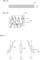
- FIG. 1A is a schematic cross-sectional view exemplifying the heat conductive material in the present disclosure
- FIG. 1B is a schematic perspective view enlarging a part of the heat conductive material in the present disclosure.
- heat conductive material 10 is, for example, a sheet shape.
- the heat conductive material 10 contains matrix resin 1 and filler F.
- the filler F includes first filler 2 that is a bar shape or a flake shape, and second filler 3 that is a bar shape or a flake shape.
- a volume resistivity of the first filler 2 is 10 12 ⁇ cm or more.
- a magnetic susceptibility of the first filler 2 is 10 -6 or less and a magnetic susceptibility of the second filler 3 is 10 -5 or more.
- the magnetic susceptibility of the second filler 3 is higher than that of the first filler 2, and thus has high magnetic field responsiveness.
- a content of the first filler 2 is more than a content of the second filler 3.
- D L designates a longitudinal direction of the filler F.
- Fill X designates the filler F of which angle of the longitudinal direction D L relative to thickness direction D T of the heat conductive material 10 is ⁇ 30° or less.
- a rate of the filler X with respect to all the filler F included in the heat conductive material 10 is 30% or more.
- the heat conductive material may achieve both of heat conductivity and insulation properties.
- heat conductivity since electronic equipment in recent years has high heat generation density and is often used under high voltage, it is important to secure the heat radiation properties and insulation properties.
- batteries also generate heat during charge and discharge, and are used under high voltage, and thus it is important to secure the heat radiation properties and insulation properties.
- a material with high conductivity (low insulation properties) such as a metal is often used as the heat radiating element, and thus the heat conductive material disposed between the heat generating element and the heat radiating element is required to have excellent insulation properties in addition to excellent heat conductivity.
- the boron nitride described in Patent Literature 1 is a material with excellent heat conductivity and insulation properties, it is a flake shape (squamous) powder, and is known to have anisotropic heat conductivity.
- the heat conductivity in the thickness direction and the heat conductivity in the in-plane direction are greatly different, and the latter is especially large.
- Patent Literature 1 discloses an orientation of the boron nitride by applying the magnetic field to the boron nitride, but since the boron nitride has low magnetic field responsiveness (low magnetic susceptibility), it is difficult to orient the boron nitride along with the thickness direction of the heat conductive material, and there is a room for improvement in improving the heat conductivity.
- Patent Literature 2 discloses that the heat conductive particle with high magnetic field responsiveness and the heat conductive particle with low magnetic field responsiveness are used together. Further, Patent Literature 2 discloses that a nickel plated graphite is used as the heat conductive particle with high magnetic field responsiveness, and discloses that the content of the heat conductive particle with high magnetic field responsiveness is more than the content of the heat conductive particle with low magnetic field responsiveness. Since the nickel plated graphite has high electric conductivity, it is difficult to express excellent insulation properties.
- Patent Literature 3 discloses a sheet shaped heat radiating material comprising: a heat conductive filler including an agglomerated hexagonal boron nitride powder having a specified orientation property index, and an aluminum oxide powder; and a silicone resin. Since the boron nitride and the aluminum oxide have low magnetic field responsiveness (low magnetic susceptibility), the orientation of the boron nitride along with the thickness direction of the heat conductive material is difficult, and there is a room for improvement in improving the heat conductivity.
- the second filler with high magnetic field responsiveness is used in addition to the first filler with low magnetic field responsiveness, and thus the second filler is a driving force of orienting the first filler. For this reason, orientation of the first filler that is a bar shape or a flake shape along with the thickness direction of the heat conductive material is easy, and further improvement of the heat conductivity may be achieved. Also, the volume resistivity of the first filler is high, and further, since the content of the first filler is more than the content of the second filler, for example, even when the second filler has electric conductivity, excellent insulation properties can be secured. Therefore, both heat conductivity and insulation properties in high level can be achieved.
- the filler in the present disclosure includes a first filler that is a bar shape or a flake shape, and a second filler that is a bar shape or a flake shape.
- the "bar shape” includes a shape referred to as a fiber shape or a needle shape
- the "flake shape” includes a shape referred to as a squamous, a thin piece shape or a plate shape.
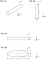
- FIG. 3A is a schematic perspective view exemplifying a bar shape filler
- FIG. 3B is a schematic plan view exemplifying the bar shape filler.
- the bar shape filler F usually has a long and narrow shape.
- the bar shape filler F has a shape of which longest part is the length of extending direction (y-axis direction in FIGS. 3A and 3B ).
- the shape of the outer periphery of the filler when cut in a plane (x-z plane) of which normal direction is the extending direction (y-axis direction) is, a perfect circle.
- the shape of the outer periphery may be shapes other than the perfect circle.
- the shapes other than the perfect circle are not particularly limited, and examples thereof may include an oval; and polygon shapes such as a square.
- FIG. 4A is a schematic side view exemplifying a flake shape filler
- FIG. 4B is a schematic plan view exemplifying the flake shape filler.
- the flake shape filler F usually has a shape of thin thickness.
- the flake shape filler F has a shape of which shortest part is the length of extending direction (thickness direction, normal direction of main surface, z-axis direction in FIGS. 4A and 4B ).
- the shape of outer periphery of the filler when viewed from the thickness direction (z-axis direction) is an oval.
- the shape of the outer periphery may be shapes other than the oval.
- the shapes other than the oval are not particularly limited, and examples thereof may include a perfect circle; and polygon shapes such as a square.
- the length of the longest part is regarded as "length a” and the length of the shortest part is regarded as "length b”.
- the length of the extending direction (longitudinal direction, y-axis direction) corresponds to "length a”
- the length of the radial direction orthogonal to the extending direction corresponds to "length b”.
- the length of the extending direction corresponds to "length b”
- the length of the longitudinal direction of the filler F viewed from the thickness direction corresponds to "length a”.
- the length of the direction orthogonal to the longitudinal direction of the filler F viewed from the thickness direction is regarded as "length c”.
- the length a, the length b and the length c are determined by the observation with an electron microscope or a CT detecting device. The number of samples used in the observation is preferably 100 or more.
- the rate of the length a with respect to the length b which is a/b is, usually larger than 1, may be 1.2 or more, and may be 1.5 or more. Meanwhile, the a/b is, for example, 15 or less and may be 10 or less.
- the length a is not particularly limited, but for example, it is 30 um or more and 100 um or less, and may be 40 um or more and 80 um or less. Meanwhile, the length b is not particularly limited, but for example, it is 3 um or more and 30 um or less, and may be 5 um or more and 20 um or less.
- the rate of the length a with respect to the length b which is a/b is usually larger than 1, may be 5 or more, and may be 10 or more. Meanwhile, the a/b is, for example, 100 or less and may be 70 or less.
- the length a is not particularly limited, but for example, it is 15 um or more and 200 um or less, and may be 20 um or more and 150 um or less.
- the length b is not particularly limited, but for example, it is 0.5 um or more and 20 um or less, and may be 1 um or more and 10 um or less.
- the rate of the length c with respect to the length b, which is c/b is, usually larger than 1, may be 5 or more, and may be 10 or more. Meanwhile, the c/b is, for example, 100 or less and may be 70 or less.
- the length c is not particularly limited, but for example, it is 15 um or more and 200 um or less, and may be 20 um or more and 150 um or less.
- the rate of the length a with respect to the length c, which is a/c is, usually larger than 1, and may be 1.2 or more. Meanwhile, the a/c is, for example, 5 or less.
- the heat conductive material in the present disclosure contains a first filler.
- the volume resistivity of the first filler is preferably high.
- the first filler preferably includes high insulation properties. The reason thereof is to obtain a heat conductive material with excellent insulation properties.
- the volume resistivity of the first filler is, usually 10 12 ⁇ cm or more, may be 10 13 ⁇ cm or more, and may be 10 14 ⁇ cm or more.
- the volume resistivity can be obtained by a constant voltage application method.
- the magnetic susceptibility of the first filler is preferably low. In other words, the magnetic field responsiveness of the first filler is preferably low.
- the magnetic susceptibility refers to a volume susceptibility (SI unit base).
- the magnetic susceptibility of the first filler is usually 10 -6 or less, and may be 10 -7 or less.
- the first filler has the magnetic susceptibility of 10 -6 or less, and may be a paramagnetic material with a positive value, and may be a diamagnetic material with a negative value of the magnetic susceptibility.
- the heat conductivity of the first filler is preferably high. By using the first filler with high heat conductivity, a heat conductive material with excellent heat conductivity is obtained. Also, the heat conductivity of the first filler is usually higher than that of the matrix resin.
- the heat conductivity of the first filler is, for example, 20 W/mK or more, may be 50 W/mK or more, and may be 100 W/mK or more.
- the heat conductivity of the first filler is, for example, 300 W/mk or less.
- the first filler is preferably an inorganic filler.
- the material of the first filler may include a boron nitride (BN), an aluminum nitride (AlN), a silicon nitride (Si 3 N 4 ), a beryllia (BeO), a magnesia (MgO), and an alumina (Al 2 O 3 ), and among them, the boron nitride (BN) is preferable, and in particular, a hexagonal boron nitride (h-BN) is preferable.
- the aspect ratio in the first filler may be larger than the aspect ratio in the second filler. The reason therefor is to facilitate the orientation of the first filler.
- the content of the first filler in the heat conductive material relative to 100 mass parts of the matrix resin is, for example, 25 mass parts or more and 90 mass parts or less, and may be 30 mass parts or more and 80 mass parts or less. Also, in the present disclosure, the content of the first filler is usually more than the content of the second filler.
- the rate of the first filler with respect to the total of the first filler and the second filler is, for example, 85 mass% or more, may be 90 mass% or more, and may be 95 mass% or more.
- the heat conductive material in the present disclosure contains a second filler.
- the magnetic susceptibility of the second filler is higher than that of the first filler. In other words, the magnetic field responsiveness of the second filler is higher than that of the first filler.
- the magnetic susceptibility of the second filler is, usually 10 -4 or more, and may be 10 -3 or more. Meanwhile, the magnetic susceptibility of the second filler is, for example, 10 6 or less.
- the second filler may be a paramagnetic material of which magnetic susceptibility is 10 -4 or more and 10 -3 or less, may be a ferromagnetic material of which magnetic susceptibility is 10 2 or more, and may be a diamagnetic material of which magnetic susceptibility is a negative value.
- the second filler may be a conductor of which volume resistivity is 10 -2 ⁇ cm or less, may be a semiconductor of which volume resistivity is larger than 10 -2 ⁇ cm and less than 10 4 ⁇ cm, and may be an insulating material of which volume resistivity is 10 4 ⁇ cm or more.
- the volume resistivity can be obtained by a constant current application method or a constant voltage application method.
- the heat conductivity of the second filler is preferably high. By using the second filler with high heat conductivity, a heat conductive material with high heat conductivity is obtained. Also, the heat conductivity of the second filler is usually higher than that of the matrix resin. The heat conductivity of the second filler is preferably higher than that of the first filler.
- the second filler is preferably an inorganic filler.
- the material of the second filler may include a carbon, a metal and a metal oxide.
- the metal may include a nickel, an iron and a cobalt.
- the metal oxide may include an iron oxide, a chrome oxide, and a ferrite.
- Specific examples of the second filler may include a carbon fiber, a metal fiber and a metal oxide fiber.
- the second filler when the second filler is a bar shape, the second filler may include a base material that is the bar shape, and a coating layer that covers a surface of the base material.
- the bar shape based material may include a carbon fiber, a metal fiber and a resin fiber.
- the coating layer preferably contains the above described carbon, metal or metal oxide.
- Specific examples of such a second filler may include a filler including a carbon fiber and a nickel layer that covers a surface of the carbon fiber.
- the content of the second filler in the heat conductive material relative to 100 mass parts of the matrix resin is, for example, 0.2 mass parts or more and 15 mass parts or less, and may be 1 mass part or more and 10 mass parts or less.
- the heat conductive material in the present disclosure usually contains the first filler and the second filler as a main component of the filler.
- the heat conductive material may contain just the first filler and the second filler, and may further include an additional filler in addition to the first filler and the second filler.
- the ratio of the total of the first filler and the second filler with respect to all the fillers included in the heat conductive material is, usually 50 mass% or more, may be 70 mass% or more, and may be 90 mass% or more.
- the ratio of the filler with respect to the total of the matrix resin and the filler is, for example, 20 mass% or more and less than 50 mass%, and may be 25 mass% or more and 45 mass% or less. Also, the ratio of the filler with respect to the total of the matrix resin and the filler is, for example, 10 volume% or more and 40 volume% or less, and may be 15 volume% or more and 35 volume% or less.
- D L designates a longitudinal direction of the filler F.
- Fill X designates the filler F of which angle of the longitudinal direction D L relative to thickness direction D T of the heat conductive material 10 is ⁇ 30° or less.
- the rate of the filler X with respect to all the filler F included in the heat conductive material 10 is 30% or more.
- the rate of the filler X may be 50% or more, may be 65% or more, may be 70% or more, may be 75% or more, and may be 80% or more. When the rate of the filler X is large, the heat conductivity further improves.
- the heat conductive material in the present disclosure contains a matrix resin.
- the matrix resin preferably has high volume resistivity.
- the matrix resin preferably has high insulation properties.
- the volume resistivity of the matrix resin is, for example, 10 12 ⁇ cm or more, may be 10 13 ⁇ cm or more, and may be 10 14 ⁇ cm or more.
- the volume resistivity can be obtained by a constant voltage application method.
- the magnetic susceptibility of the matrix resin is usually low.
- the magnetic susceptibility of the matrix resin is, for example, 10 -6 or less and may be 10 -7 or less.
- the heat conductivity of the matrix resin is usually lower than that of the filler.
- the heat conductivity of the matrix resin is, for example, 1 W/mK or less, may be 0.5 W/mK or less.
- the matrix resin is preferably a cured product of a curable resin.
- the curable resin may be a thermosetting resin, and may be an ionizing radiation curable resin.
- the thermosetting resin may include a silicone resin and an epoxy resin.
- the silicone resin may include a straight silicone resin such as a methyl silicone resin, a methyl phenyl silicone resin, and a phenyl silicone resin; and an organic resin modified silicone resin such as an alkyd modified silicone resin, a polyester modified silicone resin, an urethane modified silicone resin, an epoxy modified silicone resin, and an acryl modified silicone resin.
- examples of a curing agent that cures the silicone resin may include a normal temperature curing agent such as an organic titanate-based curing agent; a catalyst type curing agent such as a zinc dioctoate; and a reactive type curing agent such as a silane coupling agent.
- a normal temperature curing agent such as an organic titanate-based curing agent
- a catalyst type curing agent such as a zinc dioctoate
- a reactive type curing agent such as a silane coupling agent.
- the epoxy resin may include a bis phenol A type epoxy resin, a novolac type epoxy resin, an alicyclic type epoxy resin, a long-chain aliphatic type epoxy resin, a glycidyl ester type epoxy resin, and a glycidyl amine type epoxy resin.
- the curing agent that cures the epoxy resin may include an amine-based curing agent, an acid anhydrite-based curing agent, and a polyamide curing agent.
- the thermosetting resin may be a one liquid curing type, and may be a two liquid curing type.
- the content of the matrix resin in the heat conductive material is, for example, 50 mass% or more and 85 mass% or less, and may be 60 mass% or more and 80 mass% or less.
- the heat conductive material in the present disclosure contains a matrix resin and a filler.
- the details of the matrix resin and the filler are as described above.
- the dielectric breakdown voltage of the heat conductive material in the thickness direction is preferably high. In specific, the dielectric breakdown voltage of the heat conductive material in the thickness direction is preferably 5 kV/mm or more.
- the heat conductivity of the heat conductive material in the thickness direction is preferably high. In specific, the heat conductivity of the heat conductive material in the thickness direction is, for example, 2.03 W/mK or more, may be 2.36 W/mK or more, and may be 3.14 W/mK or more.
- the shape of the heat conductive material may include a sheet shape.
- the "sheet shape” includes a shape referred to as a film shape or a plate shape.
- the heat conductive material may be an arbitrary three-dimensional shape.
- the applications of the heat conductive material and examples thereof may include a battery module; electronic parts such as LED and home appliances; and an information communication module such as optical communication apparatus.
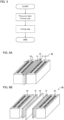
- FIG. 5 is a flow chart exemplifying the method for producing the heat conductive material in the present disclosure.
- a precursor layer is formed using a resin composition containing a curable resin for forming the matrix resin, and the filler (a precursor layer forming step).
- the thermosetting resin is cured by applying a magnetic field to the precursor layer from the thickness direction while orienting the filler in the precursor layer (a curing step).
- the heat conductive material that achieves both heat conductivity and insulation properties is obtained.
- the precursor layer forming step in the present disclosure is a step of forming a precursor layer using a resin composition containing a curable resin for forming the matrix resin, and the filler.
- the resin composition includes the first filler and the second filler as the filler.
- the resin composition may contain a curing agent that cures the curable resin.
- the details of the curable resin, the filler and the curing agent are in the same contents as those described in "A. Heat conductive material" above.
- the viscosity of the curable resin is, for example, preferably 1 Pa ⁇ s or less.
- the reason therefor is to facilitate orientation of the filler along with the magnetic field to be applied when curing the curable resin.
- Examples of the method for forming the precursor layer may include a method of coating the base material with the resin composition. There are no particular limitations on the kind of the base material, and examples thereof may include a heat radiating material.
- the curing step in the present disclosure is a step of curing the curable resin by applying a magnetic field to the precursor layer from the thickness direction while orienting the filler in the precursor layer.
- the magnetic field is applied to the precursor layer from the thickness direction.
- bar shape or flake shape filler is oriented along with the thickness direction.
- the magnetic flux density of the magnetic field to be applied is not particularly limited, and for example, it is 0.5 T or more and 10 T or less.
- the curable resin is a thermosetting resin
- the thermosetting resin may be cured at a normal temperature (room temperature), and the thermosetting resin may be cured by heating.
- the curable resin is an ionizing radiation curable resin
- the ionizing radiation curable resin is cured by irradiating an ionizing radiation ray (such as an ultraviolet ray).
- the heat conductive material obtained by the above described steps is in the same contents as those described in "A. Heat conductive material" above; thus, the descriptions herein are omitted.
- FIG. 6A is a schematic perspective view exemplifying the battery module in the present disclosure
- FIG. 6B is an exploded view of FIG. 6A
- the battery module 40 shown in FIGS. 6A and 6B includes battery 20, heat radiating material 30, and heat conductive material 10 disposed between the battery 20 and the heat radiating material 30.
- the battery module when the above described heat conductive material is disposed between the battery and the heat radiating material, the battery module may have excellent heat radiation properties and insulation properties.
- the battery in the present disclosure usually includes at least one cell.
- the cell usually includes a power generating element and an outer package that covers the power generating element.
- the power generating element usually includes at least one power generating unit including a cathode, an anode, and an electrolyte layer disposed between the cathode and the anode.
- the battery 20 shown in FIGS. 6A and 6B includes a plurality of cell C arranged along with one direction.
- the heat radiating material in the present disclosure is a material that receives heat generated by a chemical reaction of a battery, and radiates heat to the other medium.
- heat radiating material there are no particular limitations on the kind of the heat radiating material, and known heat radiating materials (such as a cooling material) can be used.
- the heat conductive material in the present disclosure is disposed between the battery and the heat radiating material.
- the heat conductive material is in the same contents as those described in "A. Heat conductive material" above.
- Examples of the applications of the battery module in the present disclosure may include a power source for vehicles such as hybrid electric vehicles (HEV), plug-in hybrid electric vehicles (PHEV), battery electric vehicles (BEV), gasoline-fueled automobiles and diesel powered automobiles.
- a power source for vehicles such as hybrid electric vehicles (HEV), plug-in hybrid electric vehicles (PHEV), battery electric vehicles (BEV), gasoline-fueled automobiles and diesel powered automobiles.
- HEV hybrid electric vehicles
- PHEV plug-in hybrid electric vehicles
- BEV battery electric vehicles
- the battery module in the present disclosure may be used as a power source for moving bodies other than vehicles (such as rail road transportation, vessel and airplane), and may be used as a power source for electronic products such as information processing equipment.
- the present disclosure is not limited to the embodiments.
- the embodiments are exemplification, and any other variations are intended to be included in the technical scope of the present disclosure if they have substantially the same constitution as the technical idea described in the claims of the present disclosure and have similar operation and effect thereto.
- thermosetting resin a normal temperature curable silicone resin (viscosity: 650 mPa ⁇ s, volume resistivity: 10 14 ⁇ cm to 10 16 ⁇ cm, from Shin-Etsu Chemical Co., Ltd.) was prepared, as a first filler, a boron nitride (from Momentive) was prepared, and as a second filler, a carbon fiber (from Mitsubishi Chemical Group Corporation) was prepared.
- the details of the first filler and the second filler are as follows.
- thermosetting resin was weighed to be 75 mass parts, the first filler was weighed to be 24 mass parts, and the second filler was weighed to be 1 mass part, and those were mixed and agitated using a rotating/revolving mixer.
- the obtained composition was poured into a container for curing (10mm thick), and placed still for 90 minutes at a normal temperature while applying magnetic field with magnetic flux density of 8T from up and down surfaces of the thickness direction using a magnetic field forming device with a pulse magnetizing coil, and thereby the thermosetting resin was cured. In this manner, a sheet shape heat conductive material was obtained.
- thermosetting resin thermosetting resin
- first filler thermosetting resin
- second filler thermosetting resin
- a heat conductive material was respectively obtained in the same manner as in Example 1, except that the blending amount of the thermosetting resin, the first filler and the second filler was respectively changed as shown in Table 4, and further, the magnetic field was not applied.
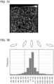
- FIG. 7A is a binarized image of the cross-section of the heat conductive material obtained in Example 3
- FIG. 7B is a histogram categorized by angles of the filler in FIG. 7A in the longitudinal direction relative to the thickness direction of the heat conductive material.
- FIG. 7A is a binarized image of the cross-section of the heat conductive material obtained in Example 3
- FIG. 7B is a histogram categorized by angles of the filler in FIG. 7A in the longitudinal direction relative to the thickness direction of the heat conductive material.
- FIG. 7B is a histogram categorized by angles of the filler in FIG. 7A in the longitudinal direction relative to the thickness direction of the heat conductive material.
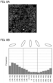
- FIG. 8A is a binarized image of the cross-section of the heat conductive material obtained in Comparative Example 9, and FIG. 8B is a histogram categorized by angles of the filler in FIG. 8A in the longitudinal direction relative to the thickness direction of the heat conductive material.
- FIGS. 7A and 7B when the magnetic field was applied, the rate of the filler X was 84%, which was high.
- FIGS. 8A and 8B when the magnetic field was not applied, the rate of the filler X was 23%, which was low.
- the heat conductivity of the heat conductive materials obtained in Examples 1 to 4 and Comparative Examples 1 to 11 was respectively measured.
- the heat conductivity of the heat conductive materials was measured by a steady state method (heat flowmeter method). The results are shown in Table 3 and Table 4.
- the dielectric breakdown voltage (BDV) of the heat conductive materials obtained in Examples 1 to 4 and Comparative Examples 1 to 11 was respectively measured.
- the voltage when dielectric breakdown occurred was divided by the thickness of the heat conductive material to obtain the dielectric breakdown voltage.
- Table 3 The results are shown in Table 3 and Table 4. [Table 3] Comp. Ex. 1 Comp. Ex. 2 Comp. Ex.
- FIG. 9 is a graph showing the relation of the filler amount and the heat conductivity in Examples 1 to 4 and Comparative Examples 1 to 10.
- Table 3 and Table 4 in Comparative Examples 4 to 6, the first filler was used, but the second filler was not used, and the magnetic field was not applied when curing the thermosetting resin, and thus the filler was not oriented along with the thickness direction, and the heat conductivity in the thickness direction was low.
- the heat conductivity did not improve even when the filler amount was increased.
- the dielectric breakdown voltage was high and excellent insulation properties were obtained.
- Comparative Examples 7 to 10 both of the first filler and the second filler were used, but the magnetic field was not applied when curing the thermosetting resin, and thus the filler was not oriented along with the thickness direction, and the heat conductivity in the thickness direction was low. Also, in Comparative Examples 7 to 10, the heat conductivity did not improve even when the filler amount was increased. In Comparative Example 10, degrade in the dielectric breakdown voltage was confirmed. This is presumably because the ratio of the second filler that had high conductivity was too much. Also, in Comparative Example 11, the second filler was used, but the first filler that had high heat conductivity was not used, and further, the magnetic field was not applied when curing the thermosetting resin, and thus the heat conductivity was low. Also, since the second filler had high conductivity, the dielectric breakdown voltage was low, and thus excellent insulation properties were not obtained.
- Comparative Examples 1 to 3 the first filler was used, and the second filler was not used, but the magnetic field was applied when curing the thermosetting resin, and thus the filler was oriented along with the thickness direction, and the heat conductivity was comparatively high. Also, in Comparative Examples 1 to 3, when the filler amount was increased, the heat conductivity improved, and the dielectric breakdown voltage was also high.
Landscapes
- Chemical & Material Sciences (AREA)
- Chemical Kinetics & Catalysis (AREA)
- Organic Chemistry (AREA)
- Engineering & Computer Science (AREA)
- Polymers & Plastics (AREA)
- Medicinal Chemistry (AREA)
- Health & Medical Sciences (AREA)
- Electrochemistry (AREA)
- General Chemical & Material Sciences (AREA)
- Manufacturing & Machinery (AREA)
- Materials Engineering (AREA)
- Life Sciences & Earth Sciences (AREA)
- Wood Science & Technology (AREA)
- Thermal Sciences (AREA)
- Combustion & Propulsion (AREA)
- Physics & Mathematics (AREA)
- Inorganic Chemistry (AREA)
- Compositions Of Macromolecular Compounds (AREA)
- Cooling Or The Like Of Electrical Apparatus (AREA)
Applications Claiming Priority (1)
| Application Number | Priority Date | Filing Date | Title |
|---|---|---|---|
| JP2023083094A JP7798080B2 (ja) | 2023-05-19 | 2023-05-19 | 熱伝導性部材、熱伝導性部材の製造方法、および、電池モジュール |
Publications (1)
| Publication Number | Publication Date |
|---|---|
| EP4465415A1 true EP4465415A1 (de) | 2024-11-20 |
Family
ID=90971464
Family Applications (1)
| Application Number | Title | Priority Date | Filing Date |
|---|---|---|---|
| EP24173789.9A Pending EP4465415A1 (de) | 2023-05-19 | 2024-05-02 | Wärmeleitendes material, verfahren zur herstellung des wärmeleitenden materials und batteriemodul |
Country Status (5)
| Country | Link |
|---|---|
| US (1) | US20240387901A1 (de) |
| EP (1) | EP4465415A1 (de) |
| JP (1) | JP7798080B2 (de) |
| KR (1) | KR20240167581A (de) |
| CN (1) | CN118994909A (de) |
Citations (5)
| Publication number | Priority date | Publication date | Assignee | Title |
|---|---|---|---|---|
| JP2001172398A (ja) | 1999-12-17 | 2001-06-26 | Polymatech Co Ltd | 熱伝導性成形体およびその製造方法 |
| WO2019031458A1 (ja) | 2017-08-10 | 2019-02-14 | デンカ株式会社 | 低誘電率熱伝導性放熱部材 |
| JP2021038353A (ja) | 2019-09-05 | 2021-03-11 | 富士高分子工業株式会社 | 熱伝導性樹脂成形体 |
| WO2022176854A1 (ja) * | 2021-02-18 | 2022-08-25 | デクセリアルズ株式会社 | 熱伝導性シートの製造方法及び熱伝導性シート |
| US20220289932A1 (en) * | 2019-09-30 | 2022-09-15 | Sekisui Polymatech Co., Ltd. | Thermally conductive sheet and method for producing same |
Family Cites Families (3)
| Publication number | Priority date | Publication date | Assignee | Title |
|---|---|---|---|---|
| JP2008266586A (ja) * | 2007-03-27 | 2008-11-06 | Toyoda Gosei Co Ltd | 低電気伝導性高放熱性高分子材料及び成形体 |
| JP2009010296A (ja) * | 2007-06-29 | 2009-01-15 | Nitto Denko Corp | 熱伝導性接着フィルム及びその製造方法 |
| JP6165603B2 (ja) * | 2013-11-28 | 2017-07-19 | 住友理工株式会社 | エラストマー成形体およびその製造方法 |
-
2023
- 2023-05-19 JP JP2023083094A patent/JP7798080B2/ja active Active
-
2024
- 2024-04-24 KR KR1020240054828A patent/KR20240167581A/ko active Pending
- 2024-04-26 CN CN202410510659.5A patent/CN118994909A/zh active Pending
- 2024-05-02 EP EP24173789.9A patent/EP4465415A1/de active Pending
- 2024-05-06 US US18/655,944 patent/US20240387901A1/en active Pending
Patent Citations (5)
| Publication number | Priority date | Publication date | Assignee | Title |
|---|---|---|---|---|
| JP2001172398A (ja) | 1999-12-17 | 2001-06-26 | Polymatech Co Ltd | 熱伝導性成形体およびその製造方法 |
| WO2019031458A1 (ja) | 2017-08-10 | 2019-02-14 | デンカ株式会社 | 低誘電率熱伝導性放熱部材 |
| JP2021038353A (ja) | 2019-09-05 | 2021-03-11 | 富士高分子工業株式会社 | 熱伝導性樹脂成形体 |
| US20220289932A1 (en) * | 2019-09-30 | 2022-09-15 | Sekisui Polymatech Co., Ltd. | Thermally conductive sheet and method for producing same |
| WO2022176854A1 (ja) * | 2021-02-18 | 2022-08-25 | デクセリアルズ株式会社 | 熱伝導性シートの製造方法及び熱伝導性シート |
Also Published As
| Publication number | Publication date |
|---|---|
| JP7798080B2 (ja) | 2026-01-14 |
| JP2024166766A (ja) | 2024-11-29 |
| US20240387901A1 (en) | 2024-11-21 |
| CN118994909A (zh) | 2024-11-22 |
| KR20240167581A (ko) | 2024-11-27 |
Similar Documents
| Publication | Publication Date | Title |
|---|---|---|
| EP3138881B1 (de) | Wärmeleitfähige polymerzusammensetzung und wärmeleitfähiger formkörper | |
| US10116018B2 (en) | Cure in place thermal interface material | |
| US8193633B2 (en) | Heat conductive sheet and method for producing same, and powder module | |
| US7608315B2 (en) | Insulator with high thermal conductivity and method for producing the same | |
| US20120286194A1 (en) | Thermal conductive sheet, insulating sheet, and heat dissipating member | |
| US20020050585A1 (en) | Heat conductive adhesive film and manufacturing method thereof and electronic component | |
| US20130065987A1 (en) | Thermal conductive sheet and producing method thereof | |
| US20120285674A1 (en) | Thermal conductive sheet, insulating sheet, and heat dissipating member | |
| EP3150680A1 (de) | Wärmeleitende elektrisch leitende klebstoffzusammensetzung | |
| EP3644353A1 (de) | Wärmeableitfolie, verfahren zur herstellung einer wärmeableitfolie und laminat | |
| TWI869662B (zh) | 氮化硼粉末及樹脂組成物 | |
| CN110603609A (zh) | 绝缘性片材以及叠层体 | |
| EP3643753A1 (de) | Harzmaterial, verfahren zur herstellung von harzmaterial und laminat | |
| EP3865543B1 (de) | Harzzusammensetzung, gehärtetes harzprodukt und verbundformkörper | |
| JP7737984B2 (ja) | 樹脂組成物及び電子部品 | |
| EP4465415A1 (de) | Wärmeleitendes material, verfahren zur herstellung des wärmeleitenden materials und batteriemodul | |
| KR20230156793A (ko) | 질화붕소 입자, 그 제조 방법, 및 수지 조성물 | |
| EP1387860B1 (de) | Formmasse zur herstellung von bipolaren platten | |
| JP5095136B2 (ja) | 半導体封止用樹脂組成物の製造方法 | |
| CN1196143C (zh) | 磁粉和粘合磁铁 | |
| TWI864381B (zh) | 氮化硼粉末及樹脂組成物 | |
| JP2017155226A (ja) | エラストマー成形体およびその製造方法 | |
| KR102854947B1 (ko) | 중공부를 갖는 질화 붕소 입자를 함유하는 시트 | |
| EP4460160A1 (de) | Material zur unterdrückung elektromagnetischer interferenzen |
Legal Events
| Date | Code | Title | Description |
|---|---|---|---|
| PUAI | Public reference made under article 153(3) epc to a published international application that has entered the european phase |
Free format text: ORIGINAL CODE: 0009012 |
|
| STAA | Information on the status of an ep patent application or granted ep patent |
Free format text: STATUS: REQUEST FOR EXAMINATION WAS MADE |
|
| 17P | Request for examination filed |
Effective date: 20240519 |
|
| AK | Designated contracting states |
Kind code of ref document: A1 Designated state(s): AL AT BE BG CH CY CZ DE DK EE ES FI FR GB GR HR HU IE IS IT LI LT LU LV MC ME MK MT NL NO PL PT RO RS SE SI SK SM TR |