EP4464633A2 - Fördersystem mit mehreren auslässen - Google Patents
Fördersystem mit mehreren auslässen Download PDFInfo
- Publication number
- EP4464633A2 EP4464633A2 EP24204482.4A EP24204482A EP4464633A2 EP 4464633 A2 EP4464633 A2 EP 4464633A2 EP 24204482 A EP24204482 A EP 24204482A EP 4464633 A2 EP4464633 A2 EP 4464633A2
- Authority
- EP
- European Patent Office
- Prior art keywords
- products
- conveying
- conveying means
- downstream
- accumulation surface
- Prior art date
- Legal status (The legal status is an assumption and is not a legal conclusion. Google has not performed a legal analysis and makes no representation as to the accuracy of the status listed.)
- Pending
Links
Images


Classifications
-
- B—PERFORMING OPERATIONS; TRANSPORTING
- B65—CONVEYING; PACKING; STORING; HANDLING THIN OR FILAMENTARY MATERIAL
- B65G—TRANSPORT OR STORAGE DEVICES, e.g. CONVEYORS FOR LOADING OR TIPPING, SHOP CONVEYOR SYSTEMS OR PNEUMATIC TUBE CONVEYORS
- B65G47/00—Article or material-handling devices associated with conveyors; Methods employing such devices
- B65G47/52—Devices for transferring articles or materials between conveyors i.e. discharging or feeding devices
- B65G47/68—Devices for transferring articles or materials between conveyors i.e. discharging or feeding devices adapted to receive articles arriving in one layer from one conveyor lane and to transfer them in individual layers to more than one conveyor lane or to one broader conveyor lane, or vice versa, e.g. combining the flows of articles conveyed by more than one conveyor
- B65G47/71—Devices for transferring articles or materials between conveyors i.e. discharging or feeding devices adapted to receive articles arriving in one layer from one conveyor lane and to transfer them in individual layers to more than one conveyor lane or to one broader conveyor lane, or vice versa, e.g. combining the flows of articles conveyed by more than one conveyor the articles being discharged or distributed to several distinct separate conveyors or to a broader conveyor lane
-
- B—PERFORMING OPERATIONS; TRANSPORTING
- B65—CONVEYING; PACKING; STORING; HANDLING THIN OR FILAMENTARY MATERIAL
- B65G—TRANSPORT OR STORAGE DEVICES, e.g. CONVEYORS FOR LOADING OR TIPPING, SHOP CONVEYOR SYSTEMS OR PNEUMATIC TUBE CONVEYORS
- B65G47/00—Article or material-handling devices associated with conveyors; Methods employing such devices
- B65G47/52—Devices for transferring articles or materials between conveyors i.e. discharging or feeding devices
- B65G47/68—Devices for transferring articles or materials between conveyors i.e. discharging or feeding devices adapted to receive articles arriving in one layer from one conveyor lane and to transfer them in individual layers to more than one conveyor lane or to one broader conveyor lane, or vice versa, e.g. combining the flows of articles conveyed by more than one conveyor
- B65G47/681—Devices for transferring articles or materials between conveyors i.e. discharging or feeding devices adapted to receive articles arriving in one layer from one conveyor lane and to transfer them in individual layers to more than one conveyor lane or to one broader conveyor lane, or vice versa, e.g. combining the flows of articles conveyed by more than one conveyor from distinct, separate conveyor lanes
-
- B—PERFORMING OPERATIONS; TRANSPORTING
- B65—CONVEYING; PACKING; STORING; HANDLING THIN OR FILAMENTARY MATERIAL
- B65G—TRANSPORT OR STORAGE DEVICES, e.g. CONVEYORS FOR LOADING OR TIPPING, SHOP CONVEYOR SYSTEMS OR PNEUMATIC TUBE CONVEYORS
- B65G47/00—Article or material-handling devices associated with conveyors; Methods employing such devices
- B65G47/52—Devices for transferring articles or materials between conveyors i.e. discharging or feeding devices
- B65G47/68—Devices for transferring articles or materials between conveyors i.e. discharging or feeding devices adapted to receive articles arriving in one layer from one conveyor lane and to transfer them in individual layers to more than one conveyor lane or to one broader conveyor lane, or vice versa, e.g. combining the flows of articles conveyed by more than one conveyor
- B65G47/69—Devices for transferring articles or materials between conveyors i.e. discharging or feeding devices adapted to receive articles arriving in one layer from one conveyor lane and to transfer them in individual layers to more than one conveyor lane or to one broader conveyor lane, or vice versa, e.g. combining the flows of articles conveyed by more than one conveyor the articles being accumulated temporarily
-
- B—PERFORMING OPERATIONS; TRANSPORTING
- B65—CONVEYING; PACKING; STORING; HANDLING THIN OR FILAMENTARY MATERIAL
- B65G—TRANSPORT OR STORAGE DEVICES, e.g. CONVEYORS FOR LOADING OR TIPPING, SHOP CONVEYOR SYSTEMS OR PNEUMATIC TUBE CONVEYORS
- B65G47/00—Article or material-handling devices associated with conveyors; Methods employing such devices
- B65G47/74—Feeding, transfer, or discharging devices of particular kinds or types
- B65G47/84—Star-shaped wheels or devices having endless travelling belts or chains, the wheels or devices being equipped with article-engaging elements
- B65G47/841—Devices having endless travelling belts or chains equipped with article-engaging elements
- B65G47/845—Devices having endless travelling belts or chains equipped with article-engaging elements the article engaging elements being pushers moving in parallel and independently from the supporting conveyor
-
- B—PERFORMING OPERATIONS; TRANSPORTING
- B65—CONVEYING; PACKING; STORING; HANDLING THIN OR FILAMENTARY MATERIAL
- B65G—TRANSPORT OR STORAGE DEVICES, e.g. CONVEYORS FOR LOADING OR TIPPING, SHOP CONVEYOR SYSTEMS OR PNEUMATIC TUBE CONVEYORS
- B65G47/00—Article or material-handling devices associated with conveyors; Methods employing such devices
- B65G47/74—Feeding, transfer, or discharging devices of particular kinds or types
- B65G47/82—Rotary or reciprocating members for direct action on articles or materials, e.g. pushers, rakes, shovels
Definitions
- the present invention relates to the industrial processing of products in a chain in a line of the packaging line type, and has as its subject, on the one hand, a conveying device and, on the other hand, a method implementing this device.
- CA2146444 discloses a solution in which a bulk product stream is separated into lanes for a single product at a time, and then, by changing direction, these lanes create streams of several products each wide.
- problems there are many problems both in separating a staggered stream into several lanes and in obtaining non-staggered matrices downstream.
- DE1786484 discloses a solution for dividing a single-line flow into several lanes, using a transfer wheel that releases the products into the lanes.
- a transfer wheel that releases the products into the lanes.
- such a principle does not allow for accumulation and only creates large flows of a single product at the output.
- EP 2402269 still offers, for example, a solution for diverting a multi-line upstream flow to different corridors.
- This principle is based on controlled pushers that divert the product depending on its position.
- it is difficult to adapt such a principle to large output flows of several products, as well as to a large number of flows in parallel.
- the rate is limited and the possibilities for accumulation are zero.
- the invention proposes to arrange an accumulation surface, bordered by the product supply on one side, and, on the other, by a transverse succession of reception zones where the products can be deposited each time on an autonomous means of movement, of the conveyor belt, trolley or other type, each reception zone serving to supply a downstream station.
- the invention thus relates to a conveying device comprising an upstream conveying means for receiving products from at least one upstream station, an accumulation surface along which the upstream conveying means circulates, a loading means for moving the products from the upstream conveying means to the accumulation surface, a downstream conveying means for releasing the products, and an unloading means for moving the products from the accumulation surface to the downstream conveying means.
- downstream conveying means comprises a plurality of independent movement means receiving the products in reception zones successively distributed from the edge of the accumulation surface opposite that along which the upstream conveying means extends.
- the invention also relates to a method implemented by this device, namely a method for conveying products circulating on an upstream conveying means which carries them in a single-line column along a conveying direction, then on a parallel downstream conveying means, comprising steps consisting of loading an accumulation surface by pushing the products transversely onto it from the upstream conveying means, unloading the accumulation surface by moving the products transversely onto the downstream conveying means, and releasing the products by means of the movement of the downstream conveying means.
- downstream conveying means comprises a plurality of independent moving means, the products being unloaded in batches onto one or other of these independent moving means.
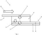
- the invention therefore firstly relates to a conveying device 1 comprising an upstream conveying means 2 for receiving products 3 from at least one upstream station, an accumulation surface 4 along which the upstream conveying means 2 circulates, a loading means 5 for moving the products 3 from the upstream conveying means 2 to the accumulation surface, a downstream conveying means 6 for releasing the products 3, and an unloading means 7 for moving the products 3 from the accumulation surface 4 to the downstream conveying means 6.
- the accumulation surface 4 is located between, on the one hand, the upstream conveying means 2 and, on the other hand, the downstream conveying means 6.
- the products 3 are preferably one behind the other in a single-line column, and therefore without staggering, in a column of one or more products 3 wide, with a gap between them, possibly uncontrollable, or in contact.
- the upstream conveying means 2 extends against the accumulation surface 4 and takes the form of at least one endless belt conveyor, on the surface of which the products 3 are placed.
- the upstream conveying means 2 may extend beyond the accumulation surface 4 to possibly feed another one.
- the conveying device 1 may in fact be provided with several different accumulation surfaces 4, distributed along the upstream conveying means 2, on one side or the other.
- the accumulation surface 4 may be a dead plate or a conveyor which moves the products 3 perpendicular to the upstream conveying means 2.
- the term "accumulation surface” means a surface arranged between two upstream and downstream pieces of equipment (in this case, for the accumulation surface 4, this is the upstream conveying means 2 and the downstream conveying means 6) making it possible to manage the flow of articles transported between these two pieces of equipment by accumulating articles in such a way, in particular, that the operation of one of the pieces of equipment can be modified (change of rate, stoppage, etc.), without impacting the operation of the other.
- the accumulation surface 4 must be large enough to be able to store a large quantity of products 3 so as to be able to better manage the flow of products 3.
- its dimension which is along the circulation of the products 3 can contain several products 3 and preferably more than 10 products 3, in particular, more than 20 products 3, preferably more than 30 products 3.
- the loading means 5 works by scanning on products 3 which are then stationary on the upstream conveying means 2, and therefore pushes the products 3 transversely on the accumulation surface 4 against which the upstream conveying means 2 circulates. The products 3 are therefore stopped when the loading means 5 acts, and a buffer solution can be provided to guarantee a continuous flow of products 3 upstream of the conveying device 1, while the products 3 must be regularly stopped.
- the upstream conveying means 2 thus drives the products 3 in a conveying direction 11 and the same applies to the downstream conveying means 6, which is on the other side of the accumulation surface 4 relative to the upstream conveying means 2. They therefore form parallel conveying solutions, on one side or the other of the accumulation surface 4.
- the loading of products 3 onto the at least one accumulation surface 4 is done for a section of the flow in the conveying direction 11 and therefore a batch of products 3, and the unloading of the at least one accumulation surface 4, on the opposite side, onto the downstream conveying means 6, is also done for a section of products 3 in this direction, preferably for a section of the same length, or even also of the same width.
- the loading 5 and unloading 7 means are therefore adapted to move several products 3 simultaneously and preferably to simultaneously move at least one column of products 3 parallel to the conveying direction 11, the length of which may in particular correspond to the length of the dimension of the accumulation surface which runs alongside the circulation of products 3 on the upstream conveyor 2.
- the loading 5 and unloading 7 means extend parallel to the conveying direction 11 over the entire length of the accumulation surface 4.
- the loading means 5 is able to deposit products 3 on the accumulation surface 4 at different locations of the latter to decorrelate the loading cycle from the unloading cycle.
- the products moved by the loading means can be deposited at any level along the axis perpendicular to the conveying direction 11.
- a row of products 3 can be arranged on the accumulation surface 4 parallel to the conveying direction 11 and against a row of products 3 already placed on this surface in order to optimize the available space. It is understood that the products 3 newly arranged on the accumulation surface 4 are closer to the upstream conveying means 2 than the products 3 which were already present on the accumulation surface 4.
- An advantage of this configuration is that it is possible to unload onto the downstream conveying means 6 products 3 which are organized in several columns according to the conveying direction 11, each single-line of a single product 3 wide, one next to the other, and therefore without any staggering or nesting of the products 3. This avoids the problems and difficulties associated with the removal of this staggering to supply a downstream device in which the products 3 circulate in corridors, such as a shrink-wrapper, for example.
- the unloading means 7 can slide on the downstream conveying means 6 several longitudinal rows of products 3 simultaneously, in particular two segments side by side of a product 3 wide each.
- the loading means 5 and the unloading means 7 may have a cover, moved by a multi-axis actuator and which comes onto the products 3, either at the level of the upstream conveying means 2 to slide them onto the at least one accumulation surface 4 transversely to the conveying direction 11, or at the level of the at least one accumulation surface 4 to slide them onto the downstream conveying means 6, again transversely to the conveying direction 11.
- a cover comes onto the products 3 to be processed from above. It may also be a simple pusher, in which case, such a pusher can simply approach the products 3 from their side, parallel to the common plane of the accumulation surface 4, the upstream conveying means 2 and the downstream conveying means 6.
- a flush mounting avoids unbalancing the products 3 when they flow towards or from the accumulation surface 4.
- a cap can be simple, such as that of the loading means 5 shown in figure 6 .
- Such a cover allows a column of products 3 to be moved at a time and comprises two substantially vertical outer edges extending along the conveying direction on either side of the column of products 3.
- a cover can also be multiple, and in particular double, such as for example that of the unloading means 7 shown in figure 6 .
- Such a cover allows several columns of products 3 to be moved at a time.
- it comprises one or more vertical plates between the outer edges parallel to the latter, and intended to separate the different columns to be moved.
- a double cover thus comprises a vertical plate between the two outer edges in order to simultaneously move two columns of products 3.
- a multiple cover advantageously makes it possible to slide several columns of products 3 simultaneously while avoiding the staggering between the products.
- the action on the products 3 of the loading means 5 and the unloading means 7 is essentially a plane thrust, preferably linear, parallel to the plane of the accumulation surface 4.
- Both the loading means 5 and the unloading means 7 may comprise an articulated robot and/or a set of slides for moving along the action to be performed on the products 3.
- the upstream conveying means 2 and the downstream conveying means 6 may each have a plurality of different conveyor belts, each being set in motion by a dedicated motor, such that the speed of circulation of these belts, and therefore of said means, is variable and controllable.
- the downstream conveying means 6 comprises a plurality of independent movement means receiving the products 3 in reception zones successively distributed from the edge of the accumulation surface 4 opposite that along which the upstream conveying means 2 extends, in particular independent movement means in the form of independent mobile carriages, or even output conveyors 8, of the belt conveyor type, each then preferably being motorized and controllable in its movement independently of the others.
- the downstream conveying means 6 has a plurality of independent movement means which follow one another perpendicular to the conveying direction 11, permanently or at least when the products 3 are discharged onto it.
- At least one independent moving means takes the form of an autonomous mobile trolley, which, to receive the products 3 from the unloading means 7, comes to be placed temporarily in one of the receiving areas, and moves to release them.
- at least one independent moving means takes the form of an independent linear output conveyor 8, extending from one of the receiving areas.
- the downstream conveying means 6 forms the output of the conveying device 1 and allows it to bring the products 3 to the downstream station, to which it must supply them.
- the at least one output conveyor 8 that the downstream conveying means 6 comprises is therefore preferably connected to the input of a treatment station ensuring the continuation of the process, directly or through at least one other conveyor.
- the output conveyors 8 are next to each other, as shown in the figures, and the same therefore applies to the receiving areas from which they extend or from which trolleys can receive the products 3.
- the receiving areas and the output conveyors 8 therefore follow one another transversely to the conveying direction 11, from the edge of the at least one accumulation surface 4 opposite that on which the upstream conveying means 2 circulates.
- the upstream conveying means 2 made up of a single conveyor or several conveyors, is on one side of the accumulation surface 4, while the downstream conveying means 6, formed by several independent movement means, is on the other side of this surface.
- Each output conveyor 8 can therefore be set in motion independently, and the same applies to trolleys. This thus makes it possible to unload the contents of the at least one accumulation surface 4 onto one or other of the movement means.
- the conveying device 1 thus has a product inlet 3, in the form of the upstream conveying means 2, and several parallel outlets.
- product 3 in the form of a downstream conveying means 6 comprising several independent output conveyors 8, or generally means of movement receiving the products 3 from reception areas distributed transversely from the edge of the accumulation surface 4.
- the unloading means 7 therefore deposits the products 3 on one or other of the output conveyors 8 or one or other of the trolleys, each time in a batch of a single column or of several columns next to each other.
- An output conveyor 8 can therefore be set in motion while another is stationary, etc. This allows the unloading means 7 to deposit products 3 on an output conveyor 8 which is stationary or at very low speed, while another output conveyor 8, on which it has previously deposited products 3, travels at a different speed to release the products 3 which are resting on it towards a downstream processing station.
- the unloading means 7 processes the products 3 closest to the edge of the accumulation surface 4 where the downstream conveying means 6 is located. It places them on one or more means of movement of the downstream conveying means 6. As these conveyors 8 are one after the other, bringing the products 3 onto one of them may require circulating them on at least one other means of movement before.
- the conveying device 1 preferably has a control unit for supervising and coordinating the operation of the upstream conveying means 2, and/or the loading means 5 and/or the unloading means 7 and/or the downstream conveying means 6, i.e. the various movement means that it comprises.
- a control unit for supervising and coordinating the operation of the upstream conveying means 2, and/or the loading means 5 and/or the unloading means 7 and/or the downstream conveying means 6, i.e. the various movement means that it comprises.
- at least one of the output conveyors 8 can circulate in both directions along its direction, which for example can be done by providing two motors for such a conveyor.
- the unloading means 7 is able to deposit products 3 in at least two different receiving areas.
- the unloading means 7 therefore works cyclically, and extracts products 3 from the at least one accumulation surface 4 to deposit them on a moving means, then returns to collect products 3 on said surface to deposit them on a moving means, possibly another, etc.
- the number of products 3 processed can change each time.
- the products 3 may be required to pass onto another means of movement before reaching the one onto which they will be released.
- the unloading means 7 is formed by a set of horizontal slides, thus parallel to the horizontal plane in which the accumulation surface 4, the upstream conveying means 2 and the downstream conveying means 6 are located, on which a gantry is mounted movable along these slides transverse to the conveying direction 11, a tool cooperating with these products 3 being mounted movable at least vertically, or even also in the conveying direction 11, to act on the products 3, by pushing them from the side, after having possibly capped them from above for better grip.
- the unloading tool 7 however preferably does not lift the products 3, which makes it possible to keep a light and dynamic tool.
- These slides preferably extend over the entire downstream conveying means 6 and therefore all of the successive receiving zones.
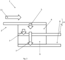
- the conveying device 1 comprises, for at least one pair of successive receiving zones, a transfer surface 9 mounted between them, in particular a transfer surface 9 mounted between two output conveyors 8.
- figure 1 shows the case of receiving areas or output conveyors 8 directly one after the other perpendicular to the conveying direction 11, while the figure 2 shows an implementation with an intercalated transfer surface.
- the transfer surface 9 is located at the same level as the two output conveyors 8 between which it is located, these two conveyors being at the same height, or at the same level as the trolleys arriving in and leaving the reception area.
- the conveying device 1 therefore has a reception surface with successive flush elements, namely the upstream conveying means 2, the accumulation surface 4, the output conveyors 8 or the upper surface of the trolleys, and the transfer surfaces 9.
- the transfer surface 9 is therefore located between two output conveyors 8, so as to form, transversely to the conveying direction 11, an alignment of an output conveyor 8, a transfer surface 9, then another output conveyor 8.
- the at least one transfer surface 9 may be a dead plate, which therefore does not carry the products 3, or a plate with particularly reduced adhesion such as with an air mattress or free rotating balls, or a surface which carries the products 3 transversely to the conveying direction 11, for example a moving belt.
- the advantage of having such a transfer surface 9 is that it is possible to have linear and parallel output conveyors 8, therefore simple and inexpensive, each directly connected to a downstream station.
- the layout is therefore such that the pitch between the downstream stations is repeated at the output conveyors 8, which therefore allows an optimal line configuration, with a conveying device 1 which distributes the products 3 that it receives on an upstream conveying means 2 to different downstream stations, by means of different parallel output conveyors 8 spaced so as to repeat the spacing of said stations.
- the products 3 therefore undergo a plane movement from the upstream conveying means 2, the accumulation surface 4, the output conveyors 8 or trolleys and the transfer surfaces 9.
- the flush transfer surface 9 makes it possible to avoid having to lift the products 3 to be brought to a straight and distant output conveyor 8, and thus makes it possible to use light and dynamic equipment.
- Such a transfer surface 9 can also be used to receive products 3 to be deposited on a means of movement even further away, and then to realize the unloading means 7 in the form of two tools 10 which work simultaneously, the first bringing products 3 which the other will process while the first loads the following ones, etc.
- the cycle times can thus be reduced, or in other words the size of the conveying device 1 transversely to the conveying direction 11 can be greatly increased and brought into line with the arrangement and spacing of the downstream stations.
- the unloading means 7 is capable of dropping products 3 onto the at least one transfer surface 9. It thus exerts a plane movement, parallel to the at least one accumulation surface 4, on the products 3 from the at least an accumulation surface 4 up to the transfer surface 9.
- the tool with which it is provided to come into contact with the products 3 is raised up to a high enough point to be able to again make a return movement towards the accumulation surface 4, parallel to it, without touching the products 3 and therefore being higher than them.
- another tool 10 of the unloading means 7 comes to grab the products 3 waiting on the transfer surface 9 and brings them onto the targeted moving means.
- the products 3 are therefore deposited while stationary by the first tool 10 while awaiting their processing by the second tool 10.
- the products 3 are stationary on a transfer surface 9, but could also be deposited by the first tool 10 on a means of movement which is then preferably stationary.
- the unloading means 7 may comprise more than two tools 10 which work one after the other on the products 3 to ensure their deposit on the predefined movement means among the plurality of downstream conveying means 6.
- the working amplitude of each tool 10 of the unloading means 7 may be all or part of the wheelbase of the conveying device 1 perpendicular to the conveying direction 11.
- the unloading means 7 comprises a single tool 10, which can release products 3 in each of the receiving zones, and, where appropriate, on each transfer surface 9.
- the unloading means 7 is therefore relatively simple.
- the same tool 10 can therefore be made to circulate above one or more means of movement before reaching the one where it must deposit the products 3.
- the unloading means 7 comprises at least two separate tools 10, which successively process the products 3, namely a first tool 10 capable of searching for products 3 on the at least one accumulation surface 4, and at least one second tool 10 capable of depositing the products 3 on a moving means, carriage or output conveyor 8.
- the unloading means 7 brings the products 3 onto at least one of the moving means thanks to the successive action of several tools 10.
- the first tool 10 of this succession releases the products 3 from the at least one accumulation surface 4, and the last tool 10 deposits the products 3 on a moving means.
- the unloading means 7 may have further tools 10, such as a third intermediate tool 10 which searches for the products 3 downstream at the accumulation surface 4 and deposits them upstream of the target moving means.
- a third intermediate tool 10 which searches for the products 3 downstream at the accumulation surface 4 and deposits them upstream of the target moving means.
- Each tool 10 can therefore be moved independently of the other tool(s) 10.
- the different tools 10 can be moved on the same set of slides or rail.
- At least one transfer surface 9 forms a buffer zone where products 3 can be temporarily stored intermediately between the accumulation surface 4 and the independent moving means which must release them.
- the unloading means 7 acts in two stages to bring the products 3 onto the relevant moving means. This also means that the unloading means 7 can simultaneously manage several batches of products 3 to bring them to the correct moving means, each batch corresponding to a group of products 3 initially extracted at one time from the accumulation surface 4.
- the products 3 therefore pass through at least one intermediate buffer zone between the accumulation surface 4 and the intended means of movement.
- bringing the group of products 3 onto the correct means of movement is possibly done with more than two tool maneuvers 10.
- the at least one transfer surface 9 is a motorized drive surface and drives the products 3 transversely in the direction of the independent movement means.
- the transfer surface 9 ensures the movement of the products 3 transversely to the conveying direction 11, in particular between two movement means, trolleys or output conveyors 8.
- the at least one output conveyor 8 can circulate, depending on the case, in one or the other direction, in particular thanks to a pair of drive motors each working at one end of the closed loop formed by the output conveyor 8. It is thus possible to obtain line layouts with downstream stations distributed on one side or the other of an axis formed by the succession of output conveyors 8 and transfer surfaces 9, in the extension of the accumulation surface 4.
- the conveying device 1 has a distribution function between one or more input channels and several output channels, each output channel being supplied at a reception zone. It can also have an accumulation function between the at least one input and the outputs, thanks to an accumulation surface 4, or even at least one transfer surface 9.
- the products 3 move in parallel on the upstream 2 and downstream 6 conveying means, arranged along opposite edges of the accumulation surface 4.
- the downstream conveying means 6 comprises a plurality of independent movement means, the products 3 being unloaded in batches onto one or other of these independent movement means, in particular in the form of output conveyors 8 or trolleys.
- the batches loaded onto the accumulation surface 4 by the loading means 5 may correspond to the batches subsequently unloaded by the unloading means 7, or even correspond to the batches released by the downstream conveying means 6. It is of course conceivable that the products 3 are processed in the form of a group of different sizes each time.
- the upstream conveying means 2, the downstream conveying means 6, the transfer surface(s) 9, are therefore in the extension of the accumulation surface 4, perpendicular to the conveying direction 11.
- the products 3 undergo, thanks to the successive action, on the one hand, of the loading means 5, then, on the other hand, of the unloading means 7, or even of the accumulation surface 4 if it is a driving surface and/or of the transfer surface(s) 9 where applicable, a movement perpendicular to the conveying direction. 11 to the downstream conveying means 6 then a movement in the conveying direction 11 thanks to the downstream conveying means 6.
- the at least one accumulation surface 4 therefore separates the upstream conveying means 2 from the downstream conveying means 6.
- the unloading means 7 extracts the products 3 from the accumulation surface 4 and arranges them in groups distributed transversely to the conveying direction 11, on a movement means, in a reception zone, or even temporarily on a transfer surface 9.
- a step can thus consist of defining the exact location where the unloading means 7 releases the products 3 temporarily or permanently, namely one of the specific means of movement, or even the transfer surface or surfaces 9.
- the release of products 3 from the accumulation surface 4 onto the independent displacement means consists of several successive transverse displacement cycles, each performed by a different tool 10, so that, during each cycle, the products 3 are successively approached to the targeted displacement means. It is thus possible for the products 3 to be deposited in the correct location by tools 10 working in parallel, which reduces the cycle time.
- the method comprises, between two movement cycles, at least one additional step of accumulating products 3 after they are taken from the accumulation surface 4 and before they are deposited on an independent movement means, in particular an accumulation step on a stationary movement means, carriage or output conveyor 8, or even an accumulation step on a transfer surface 9 located between the accumulation surface 4 and the movement means, the products 3 then being taken from the accumulation surface 4 then released onto the transfer surface 9 by the unloading means 7, then taken again from the transfer surface 9 and released onto the movement means.
- the conveying device 1 has an upstream conveying means 1 in the form of a single belt conveyor, or input conveyor 12.
- the products 3 are of the bottle, can, bag, or other vial type therefore having a great height relative to its base and thus being unstable, or of the box or crate type, which can then be much more stable.
- product 3 is either a container or not.
- the 3 products are all identical. In other words, they have the same format, are made of the same materials, and if they contain anything, they all contain the same thing.
- This accumulation surface 4 is preferably essentially rectangular, with two edges parallel to the conveying direction 11 and two perpendicular edges.
- the upstream conveying means 2 extends along one of the edges parallel to the conveying direction 11.
- the products 3 are loaded onto the upstream conveying means 2 one behind the other, in a wide column of a single product 3, or in a wide column of several products 3.
- the products 3 may optionally also be in bulk and have different orientations for each of them.
- the conveying device 1 may have a plurality of accumulation surfaces 4, which the upstream conveying means 2 then runs along each time.
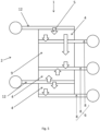
- figure 5 shows for example a conveying device 1 with an upstream conveying means 2 comprising two input conveyors 12, two accumulation surfaces 4, and a downstream conveying means 6 comprising three output conveyors 8.
- the conveying device 1 also comprises a loading means 5, which serves to move products 3 from the upstream conveying means 2 onto the at least one accumulation surface 4.
- the products 3 are thus stopped when they are to be moved onto the accumulation surface 4. They then form a stopped batch which extends against one side of the accumulation surface 4.
- the loading means 5 then pushes the batch of products 3 from the upstream conveying means 2 onto the accumulation surface 4. This action is essentially perpendicular to the conveying direction 1.
- a batch of products 3 formed of a column section of at least one product 3 wide is thus swept transversely onto the accumulation surface 4.
- the upstream conveying means 2 may include an accumulation solution which makes it possible to combine, on the one hand, a flow continuous upstream, and, on the other hand, the stopping of the products 3 for their transverse transfer by sweeping up to the accumulation surface 4.
- the products 3 loaded by transverse scanning from one side of the accumulation surface 4 along which the upstream conveying means 2 circulates are released onto the accumulation surface 4 somewhere between this side and the opposite side, in particular depending on the production needs and the products 3 already present.
- the conveying device 1 also has an unloading means 7 which aims to bring products 3, present on the accumulation surface 4, to a downstream conveying means 6, by means of which they are released and brought downstream of the conveying device 1.
- the downstream conveying means 6 comprises a plurality of separate output conveyors 8, which can therefore be controlled independently of each other.
- the downstream conveying means 6 comprises independent carriages, or even a combination of output conveyors 8 and carriages.
- the products 3 are brought onto the downstream conveying means 6 at output zones where the independent movement means, carriages or output conveyors 8, are located, temporarily or permanently.
- Each means of movement, carriage or output conveyor 8 has a speed specific to it, such that it can be in motion or stopped, independently of the state of the other means of movement.
- Each output conveyor 8 is connected to a downstream processing station that it supplies.
- the conveying device 1 can supply several downstream stations independently each time, thanks to means of movement 8 specific to them each time, and therefore operating at a rate related to the needs of said station.
- downstream station is therefore supplied by an output conveyor 8 directly or via at least one other conveyor.
- the batches of products 3 loaded onto the accumulation surface 4 thus have the same dimension in the conveying direction 11 as the batches of products 3 unloaded onto the downstream conveying means 6.
- the unloading means 7 operates by coming over the products 3 which are on the accumulation surface 4, along the edge opposite that where the upstream conveying means 2 is located. Like the loading means 5, it then pushes them by a movement parallel to the accumulation surface 4 onto the downstream conveying means 6.
- the unloading means 7 pushes a batch of at least one product 3 wide from the accumulation surface 4 onto one of the particular moving means, depending on the needs of the machine park arranged downstream.
- the unloading means 7 therefore extracts a batch of products 3 each time and deposits it on one of the moving means, in the form of a trolley or output conveyor 8.
- the unloading means 7 searches for a batch and deposits it on a moving means which may be different each time.
- the batch of products 3 extracted from the accumulation surface 4 during a cycle may be deposited in successive portions on several different moving means.
- the loading means 5 can feed the accumulation surface 4 with batches of one or even two products 3 wide, while the unloading means 7 extracts at each cycle a batch of products 3 of four, six or more products 3 wide, which then makes it possible to directly feed several bundling machines for example.
- the advantage of such a transfer surface 9 is the possibility of providing output conveyors 8 which are parallel to each other, arranged spaced apart with the same pitch as that of the stations downstream of the conveying device 1. Downstream of the conveying device 1, an island of treatment stations can in fact be installed. These stations are then next to each other, in particular perpendicular to the conveying direction 11. They are arranged with a certain pitch, defined by their structure, and for reasons of simplicity of conveying, it is then advantageous to provide linear conveyors, without curves, to feed them.
- the set of output conveyors 8 and the at least one transfer surface 9 is flush and then forms a plane on which the unloading means 7 slides the products 3 which it extracts from the accumulation surface 4.
- a batch deposited on an output conveyor 8 must however not prevent access to an output conveyor 8 further along in this sweeping movement.
- One solution is for example to ensure that the deposited batch is cleared early enough not to hinder the passage of the next batch.
- the movement means on which the unloading means 7 has brought the products 3 then starts moving while the unloading means 7 will fetch another batch of products 3 to be deposited on a means of transport located in a reception area still further away.
- the transfer surface 9 can serve as an accumulation area. For example, products 3 can be deposited there before being picked up later to be brought onto the intended output conveyor 8. This may be necessary if, taking into account the process requirements, the unloading means 7 does not have time to bring the batch of products 3 to an output conveyor 8 that is too far away. This may also be necessary to create on the transfer surface 9 a batch of larger size than that extracted from the accumulation surface 4, for example.
- the unloading means 7 therefore acts downstream of the at least one accumulation surface 4 to extract products 3 in batches and finally deposit them on one or other movement means of the downstream conveying means 6, at the reception zones.
- the unloading means 7 has at least one tool 10 which can move perpendicular to the conveying direction 11, along the output conveyors 8 and any transfer surfaces 9.
- This tool covers the products 3 to be extracted from the accumulation surface 4 by a movement perpendicular to said surface, then shifts them by a movement parallel to said surface, perpendicular to the conveying direction 11.
- the tool 10 then disengages upwards from the products 3 which it deposits and returns for a new cycle.
- the unloading means 7 can thus have a single tool 10, the range of movement of which allows it to reach all the reception zones and the possible at least one transfer surface 9.
- the unloading means 7 has a plurality of different tools 10, in particular tools 10 that work one after the other.
- the products 3 are extracted from the accumulation surface 4 during the work cycle of a first tool 10. They are deposited on a transfer surface 9 or even a movement means, and are then taken by another tool 10 of the unloading means 7. Finally, a tool 10 deposits them on the desired output conveyor 8. It is thus possible to have several tools 10 that work in masked time relative to each other, which is advantageous when the paths to be covered for the products 3 are possibly long transversely to the conveying direction 11.
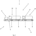
- FIG. 4 thus shows possible operating cycles for two tools 10: a loading cycle for the loading means 5, between the upstream conveying means 2 and the accumulation surface 4, an unloading cycle between the accumulation surface 4 and a transfer surface 9, then a second unloading cycle from this transfer surface 9 into the final reception zone.
- the loading means 5 has an operating cycle at the upstream conveying means 2 and the accumulation surface 4 nearby.
- the unloading means 7 has two tools 10.
- the first tool 10 can pick up the products 3 on the accumulation surface 4 and deposit them, after a short cycle, directly on the moving means 8 against the accumulation surface 4. It can also have a slightly longer cycle, not shown, and deposit the products 3 on a transfer surface 9 just after this moving means. With an even slightly longer cycle, this same tool 10 deposits the products 3 on the next transfer surface 9.
- the other tool 10 can then collect the products 3 on this transfer plate 9, on which they possibly accumulate, and bring them onto the output conveyor 8 just after, or bring them onto the last output conveyor 8, again after the third transfer surface 9.
- the products 3 can be placed waiting between two tools 10 on a transfer surface 9 or in a reception area, waiting, then stopped on a means of movement.
- the conveying device 1 provides the connection between two upstream stations and three downstream stations.
- the upstream conveying means 2 has two different input conveyors 12, each bringing the products 3 from a single machine.
- the conveying device 1 comprises a plurality of accumulation surfaces 4: one of them is against one of the input conveyors 12, two others are against the other input conveyor 12, each on one side.
- the downstream conveying means 6 comprises three output conveyors 8 and a transfer surface 9: from the first input conveyor 12, an output conveyor 8 directly after one of the accumulation surfaces 4, then a transfer surface 9, another output conveyor 8; from the second input conveyor 12, an output conveyor 8 located against each accumulation surface 4 which it runs along.
- the invention it is thus possible to feed, from a single flow of products, different machines located downstream in a controlled manner.
- the staggering between the products is avoided, and each machine can have its own input flow size.
- a particularly interesting application can be between an upstream machine which delivers finished products 3 individually, such as a blow-molding labeling machine for plastic bottles of liquid, and bundling stations requiring products 3 organized in corridors of a separate product 3.
- the unloading means 7 may comprise a set of slides perpendicular to the conveying direction 11 and parallel to the accumulation surface 4. These slides may extend above the entire succession of reception zones where the movement means come from or are located, with possibly at least one transfer surface 9. The same set of slides may be used for several tools 10 having action zones distributed successively perpendicular to the conveying direction 11.
Landscapes
- Engineering & Computer Science (AREA)
- Mechanical Engineering (AREA)
- Attitude Control For Articles On Conveyors (AREA)
- Intermediate Stations On Conveyors (AREA)
Applications Claiming Priority (3)
| Application Number | Priority Date | Filing Date | Title |
|---|---|---|---|
| FR1651383A FR3047981B1 (fr) | 2016-02-19 | 2016-02-19 | Convoyage a plusieurs sorties |
| PCT/FR2017/050361 WO2017140992A1 (fr) | 2016-02-19 | 2017-02-17 | Convoyage a plusieurs sorties |
| EP17710594.7A EP3416903B1 (de) | 2016-02-19 | 2017-02-17 | Fördersystem mit mehreren auslässen |
Related Parent Applications (2)
| Application Number | Title | Priority Date | Filing Date |
|---|---|---|---|
| EP17710594.7A Division-Into EP3416903B1 (de) | 2016-02-19 | 2017-02-17 | Fördersystem mit mehreren auslässen |
| EP17710594.7A Division EP3416903B1 (de) | 2016-02-19 | 2017-02-17 | Fördersystem mit mehreren auslässen |
Publications (2)
| Publication Number | Publication Date |
|---|---|
| EP4464633A2 true EP4464633A2 (de) | 2024-11-20 |
| EP4464633A3 EP4464633A3 (de) | 2025-03-05 |
Family
ID=55752574
Family Applications (2)
| Application Number | Title | Priority Date | Filing Date |
|---|---|---|---|
| EP24204482.4A Pending EP4464633A3 (de) | 2016-02-19 | 2017-02-17 | Fördersystem mit mehreren auslässen |
| EP17710594.7A Active EP3416903B1 (de) | 2016-02-19 | 2017-02-17 | Fördersystem mit mehreren auslässen |
Family Applications After (1)
| Application Number | Title | Priority Date | Filing Date |
|---|---|---|---|
| EP17710594.7A Active EP3416903B1 (de) | 2016-02-19 | 2017-02-17 | Fördersystem mit mehreren auslässen |
Country Status (11)
| Country | Link |
|---|---|
| US (1) | US10442635B2 (de) |
| EP (2) | EP4464633A3 (de) |
| CN (1) | CN108698771B (de) |
| DE (1) | DE202017007470U1 (de) |
| ES (1) | ES3006939T3 (de) |
| FR (1) | FR3047981B1 (de) |
| HU (1) | HUE070375T2 (de) |
| PL (1) | PL3416903T3 (de) |
| PT (1) | PT3416903T (de) |
| WO (1) | WO2017140992A1 (de) |
| ZA (1) | ZA201805514B (de) |
Families Citing this family (18)
| Publication number | Priority date | Publication date | Assignee | Title |
|---|---|---|---|---|
| US20130097975A1 (en) * | 2011-10-24 | 2013-04-25 | Remedi Technology Holdings, Llc | Packaging system for pharmaceutical dispenser and associated method |
| FR3061159B1 (fr) * | 2016-12-27 | 2020-11-13 | Gebo Packaging Solutions France | Dispositif de transfert de produits |
| FR3061161B1 (fr) * | 2016-12-28 | 2020-09-18 | Gebo Packaging Solutions France | Dispositif de transfert de produits |
| LU100590B1 (en) * | 2017-12-21 | 2019-07-25 | Soremartec Sa | Method for packaging products and corresponding packaging line |
| FR3075769B1 (fr) * | 2017-12-27 | 2021-12-17 | Gebo Packaging Solutions France | Transfert de produits entre une zone de transit et une surface d'accumulation |
| FR3081849B1 (fr) * | 2018-05-29 | 2021-04-16 | Gebo Packaging Solutions France | Transfert de produits en enserrement vers ou depuis une surface d'accumulation |
| DE102018211859A1 (de) * | 2018-07-17 | 2020-01-23 | Krones Ag | Vorrichtung und Verfahren zum Puffern von Stückgütern |
| DE102018219085A1 (de) * | 2018-11-08 | 2020-05-14 | Krones Ag | Vorrichtung zum lückenlosen und/oder staudrucklosen Verteilen eines einreihigen Behälterstroms auf wenigstens zwei Behälterströme |
| FR3088315B1 (fr) * | 2018-11-09 | 2021-06-25 | Gebo Packaging Solutions France | Dispositif de convoyage de produits et procede de gestion du transfert desdits produits |
| FR3094007B1 (fr) * | 2019-03-19 | 2021-12-17 | C E R M E X Constructions Etudes Et Rech De Materiels Pour Lemballage Dexpedition | Dispositif de regroupement de produits |
| DE102020207679A1 (de) * | 2020-06-22 | 2021-12-23 | Krones Aktiengesellschaft | Verfahren und Vorrichtung zum Puffern von Behältern |
| DE102020207677A1 (de) * | 2020-06-22 | 2021-12-23 | Krones Aktiengesellschaft | Verfahren und Vorrichtung zum Puffern von Behältern |
| DE102021100025A1 (de) | 2021-01-04 | 2022-07-07 | Krones Aktiengesellschaft | Vorrichtung und Verfahren zum Puffern von Objekten, vorzugsweise Behältern |
| EP4257521A1 (de) * | 2022-04-05 | 2023-10-11 | Sidel Participations | Produktionslinie mit mehrspurigem behälterbehandlungsmodul und verfahren zur behandlung von behältern |
| DE102021124545B4 (de) | 2021-09-22 | 2025-08-07 | Stöcklin Logistik Ag | Vorrichtung und Verfahren zur Sequenzierung von Ladeeinheiten in einer vorbestimmten Reihenfolge |
| DE102021134083A1 (de) | 2021-12-21 | 2023-06-22 | Krones Aktiengesellschaft | Verfahren und Vorrichtung zum Puffern von Behältern |
| CN116101756B (zh) * | 2022-11-16 | 2025-09-23 | 东富龙科技集团股份有限公司 | 一种多层同轨异步环形输送线结构 |
| DE102023105691A1 (de) | 2023-03-08 | 2024-09-12 | Krones Aktiengesellschaft | Transportvorrichtung für Behälter, Übergabevorrichtung für Behälter und Verfahren zum Betreiben der Transportvorrichtung |
Citations (4)
| Publication number | Priority date | Publication date | Assignee | Title |
|---|---|---|---|---|
| DE1786484A1 (de) | 1966-01-24 | 1971-10-28 | Platmanufaktur Ab | Vorrichtung zum Anordnen von Verpackungseinheiten,wie beispielsweise Flaschen,Dosen u.dgl.in mehreren Reihen nebeneinander zu Gruppen mit von oben gesehen annaehernd rechteckiger Form |
| CA2146444A1 (en) | 1993-09-02 | 1995-03-09 | Frank Moncrief | Packaging machine and method of packaging articles |
| EP2402269A1 (de) | 2010-06-30 | 2012-01-04 | Krones AG | Ausleitvorrichtung |
| WO2014076390A1 (fr) | 2012-11-16 | 2014-05-22 | Sidel Participations | Dispositif et procédé d'accumulation et de transfert |
Family Cites Families (21)
| Publication number | Priority date | Publication date | Assignee | Title |
|---|---|---|---|---|
| DE29815102U1 (de) | 1998-08-22 | 1999-03-25 | KRONES AG, 93073 Neutraubling | Scharnierbandkette in geradelaufender Ausführung |
| DE29815087U1 (de) | 1998-08-22 | 1999-03-25 | KRONES AG, 93073 Neutraubling | Kurvenförmiger Gebindetransporteur |
| EP0982246A1 (de) | 1998-08-22 | 2000-03-01 | Krones AG | Gebindetransportanlage |
| JP4164948B2 (ja) | 1999-06-30 | 2008-10-15 | シブヤマシナリー株式会社 | 容器熱処理装置のアキューム装置 |
| DE10320321A1 (de) | 2003-05-06 | 2004-12-09 | Krones Ag | Vorrichtung zum Palettieren |
| DE202005019907U1 (de) | 2005-12-19 | 2007-04-26 | Autefa Automation Gmbh | Umsetzeinrichtung für Stückgüter, insbesondere Flaschen |
| CN101720302B (zh) | 2007-05-14 | 2013-06-19 | 克朗斯股份公司 | 用于处理包装的方法及装置 |
| DE102008020622A1 (de) * | 2008-04-24 | 2009-10-29 | Krones Ag | Vorrichtung und Verfahren zum Umsortieren von Stückgutzusammenstellungen |
| EP2163498B1 (de) * | 2008-09-11 | 2011-04-06 | Motor Power Company S.r.l. | Vorrichtung zum Verschieben und Positionieren von Produkten und Maschine mit der Vorrichtung |
| FR2940788B1 (fr) * | 2009-01-06 | 2011-02-11 | Sidel Participations | Procede de groupage de produits du genre flacons ou autres |
| DE102009011302A1 (de) * | 2009-03-02 | 2010-09-09 | Kuka Roboter Gmbh | Vereinzeln von Gebindelagen |
| DE102009003847B4 (de) * | 2009-04-29 | 2025-07-10 | Krones Aktiengesellschaft | Vorrichtung und Verfahren zum Ausleiten von Objekten von einer sich bewegenden Transporteinrichtung |
| US9611102B2 (en) * | 2012-10-26 | 2017-04-04 | Illinois Tool Works Inc. | Laning robot systems and methods |
| FR2993870A1 (fr) * | 2012-11-14 | 2014-01-31 | Sidel Participations | Dispositif et procede de convoyage multivoies |
| US9359150B2 (en) * | 2013-04-12 | 2016-06-07 | Axium Inc. | Singulator |
| DE102013207091A1 (de) * | 2013-04-19 | 2014-10-23 | Krones Aktiengesellschaft | Gruppierverfahren und -vorrichtung |
| DE102013107565A1 (de) * | 2013-07-16 | 2015-01-22 | Khs Gmbh | Verfahren sowie Transportvorrichtung zum Umformen eines ersten Behälterstroms in einen zweiten Behälterstrom |
| CN204416510U (zh) * | 2014-11-13 | 2015-06-24 | 安徽双鹤药业有限责任公司 | 一种输液袋卸袋分道输送装置 |
| FR3038307B1 (fr) * | 2015-06-30 | 2019-05-31 | Gebo Packaging Solutions France | Dispositif et methode d’alimentation d’accumulation |
| EP3405418B1 (de) * | 2015-11-30 | 2021-06-09 | Sidel Canada Inc. | Verteilfördervorrichtung und förderverfahren |
| DE102016200281A1 (de) * | 2016-01-13 | 2017-07-13 | Krones Ag | Verfahren zum Umstellen des Betriebs einer Behälterbehandlungsanlage |
-
2016
- 2016-02-19 FR FR1651383A patent/FR3047981B1/fr active Active
-
2017
- 2017-02-17 WO PCT/FR2017/050361 patent/WO2017140992A1/fr not_active Ceased
- 2017-02-17 PT PT177105947T patent/PT3416903T/pt unknown
- 2017-02-17 ES ES17710594T patent/ES3006939T3/es active Active
- 2017-02-17 EP EP24204482.4A patent/EP4464633A3/de active Pending
- 2017-02-17 DE DE202017007470.2U patent/DE202017007470U1/de active Active
- 2017-02-17 EP EP17710594.7A patent/EP3416903B1/de active Active
- 2017-02-17 HU HUE17710594A patent/HUE070375T2/hu unknown
- 2017-02-17 PL PL17710594.7T patent/PL3416903T3/pl unknown
- 2017-02-17 CN CN201780011961.4A patent/CN108698771B/zh active Active
- 2017-02-17 US US16/076,665 patent/US10442635B2/en active Active
-
2018
- 2018-08-17 ZA ZA2018/05514A patent/ZA201805514B/en unknown
Patent Citations (4)
| Publication number | Priority date | Publication date | Assignee | Title |
|---|---|---|---|---|
| DE1786484A1 (de) | 1966-01-24 | 1971-10-28 | Platmanufaktur Ab | Vorrichtung zum Anordnen von Verpackungseinheiten,wie beispielsweise Flaschen,Dosen u.dgl.in mehreren Reihen nebeneinander zu Gruppen mit von oben gesehen annaehernd rechteckiger Form |
| CA2146444A1 (en) | 1993-09-02 | 1995-03-09 | Frank Moncrief | Packaging machine and method of packaging articles |
| EP2402269A1 (de) | 2010-06-30 | 2012-01-04 | Krones AG | Ausleitvorrichtung |
| WO2014076390A1 (fr) | 2012-11-16 | 2014-05-22 | Sidel Participations | Dispositif et procédé d'accumulation et de transfert |
Also Published As
| Publication number | Publication date |
|---|---|
| WO2017140992A1 (fr) | 2017-08-24 |
| EP3416903B1 (de) | 2024-11-06 |
| ZA201805514B (en) | 2019-06-26 |
| EP4464633A3 (de) | 2025-03-05 |
| FR3047981B1 (fr) | 2019-10-04 |
| EP3416903A1 (de) | 2018-12-26 |
| PL3416903T3 (pl) | 2025-03-17 |
| US10442635B2 (en) | 2019-10-15 |
| DE202017007470U1 (de) | 2021-10-18 |
| CN108698771A (zh) | 2018-10-23 |
| HUE070375T2 (hu) | 2025-06-28 |
| US20190039835A1 (en) | 2019-02-07 |
| CN108698771B (zh) | 2021-05-25 |
| PT3416903T (pt) | 2025-03-03 |
| ES3006939T3 (en) | 2025-03-19 |
| CA3012261A1 (fr) | 2017-08-24 |
| FR3047981A1 (fr) | 2017-08-25 |
Similar Documents
| Publication | Publication Date | Title |
|---|---|---|
| EP3416903B1 (de) | Fördersystem mit mehreren auslässen | |
| EP3498638B1 (de) | Vorrichtung zur versorgung eines zwischenförderer | |
| EP3317186B1 (de) | Vorrichtung und verfahren zur formung von chargen | |
| EP0761578B1 (de) | Palettiervorrichtung und Palettierverfahren | |
| FR3063984A1 (fr) | Realisation de lots de produits en vue d'une palettisation par couches | |
| FR2940795A1 (fr) | Procede et installation de groupage de produits empilables du type etuis et autres | |
| WO2019129968A1 (fr) | Déplacement de produits sur une zone de transit | |
| EP3075685B1 (de) | Beförderungsvorrichtung mithilfe eines autonomen wagens | |
| EP3732121A1 (de) | Transfer von produkten zwischen einer durchgangszone und einer sammelfläche | |
| EP3609821A1 (de) | Mehrlinientransfer von produkten | |
| WO2019228863A1 (fr) | Preparation de lots de produits | |
| EP3562771B1 (de) | Robotisierte palettierung | |
| EP3720794A1 (de) | Herstellung von chargen von produkten zum palettisieren in schichten | |
| CA3012261C (fr) | Convoyage a plusieurs sorties | |
| WO2018050990A1 (fr) | Dispositif et procédé de groupage et de transfert de caisses palettes de produits triés en lots | |
| FR3046999A1 (fr) | Dispositif et methode de transfert de produits | |
| EP4442619A1 (de) | Anlage zum speichern und transferieren von produkten | |
| WO2026087570A1 (fr) | Procédé de palettisation et installation associée | |
| FR3155822A1 (fr) | Dispositif et procédé de groupage, et installation de transfert latéral de produits | |
| WO2018083413A1 (fr) | Dispositif de manutention de produits |
Legal Events
| Date | Code | Title | Description |
|---|---|---|---|
| PUAI | Public reference made under article 153(3) epc to a published international application that has entered the european phase |
Free format text: ORIGINAL CODE: 0009012 |
|
| STAA | Information on the status of an ep patent application or granted ep patent |
Free format text: STATUS: THE APPLICATION HAS BEEN PUBLISHED |
|
| AC | Divisional application: reference to earlier application |
Ref document number: 3416903 Country of ref document: EP Kind code of ref document: P |
|
| AK | Designated contracting states |
Kind code of ref document: A2 Designated state(s): AL AT BE BG CH CY CZ DE DK EE ES FI FR GB GR HR HU IE IS IT LI LT LU LV MC MK MT NL NO PL PT RO RS SE SI SK SM TR |
|
| REG | Reference to a national code |
Ref country code: DE Ref legal event code: R079 Free format text: PREVIOUS MAIN CLASS: B65G0047840000 Ipc: B65G0047710000 |
|
| PUAL | Search report despatched |
Free format text: ORIGINAL CODE: 0009013 |
|
| AK | Designated contracting states |
Kind code of ref document: A3 Designated state(s): AL AT BE BG CH CY CZ DE DK EE ES FI FR GB GR HR HU IE IS IT LI LT LU LV MC MK MT NL NO PL PT RO RS SE SI SK SM TR |
|
| RIC1 | Information provided on ipc code assigned before grant |
Ipc: B65G 47/84 20060101ALI20250129BHEP Ipc: B65G 47/71 20060101AFI20250129BHEP |
|
| STAA | Information on the status of an ep patent application or granted ep patent |
Free format text: STATUS: REQUEST FOR EXAMINATION WAS MADE |
|
| 17P | Request for examination filed |
Effective date: 20250904 |