EP4464419A2 - Ultraschallzerstäubungsvorrichtung - Google Patents
Ultraschallzerstäubungsvorrichtung Download PDFInfo
- Publication number
- EP4464419A2 EP4464419A2 EP24204616.7A EP24204616A EP4464419A2 EP 4464419 A2 EP4464419 A2 EP 4464419A2 EP 24204616 A EP24204616 A EP 24204616A EP 4464419 A2 EP4464419 A2 EP 4464419A2
- Authority
- EP
- European Patent Office
- Prior art keywords
- cup
- ultrasonic
- thin film
- source solution
- separator
- Prior art date
- Legal status (The legal status is an assumption and is not a legal conclusion. Google has not performed a legal analysis and makes no representation as to the accuracy of the status listed.)
- Pending
Links
- 238000000889 atomisation Methods 0.000 title claims abstract description 81
- 239000000470 constituent Substances 0.000 claims abstract description 20
- 239000000463 material Substances 0.000 claims abstract description 19
- 239000004810 polytetrafluoroethylene Substances 0.000 claims abstract description 15
- 229920001343 polytetrafluoroethylene Polymers 0.000 claims abstract description 15
- 239000010409 thin film Substances 0.000 claims description 46
- XLYOFNOQVPJJNP-UHFFFAOYSA-N water Substances O XLYOFNOQVPJJNP-UHFFFAOYSA-N 0.000 claims description 25
- -1 polytetrafluoroethylene Polymers 0.000 claims description 9
- 239000003595 mist Substances 0.000 abstract description 26
- 239000011347 resin Substances 0.000 abstract description 11
- 229920005989 resin Polymers 0.000 abstract description 11
- NBVXSUQYWXRMNV-UHFFFAOYSA-N fluoromethane Chemical compound FC NBVXSUQYWXRMNV-UHFFFAOYSA-N 0.000 abstract description 9
- 239000010408 film Substances 0.000 description 28
- 239000007789 gas Substances 0.000 description 18
- 238000010586 diagram Methods 0.000 description 10
- YXFVVABEGXRONW-UHFFFAOYSA-N Toluene Chemical compound CC1=CC=CC=C1 YXFVVABEGXRONW-UHFFFAOYSA-N 0.000 description 9
- 239000004743 Polypropylene Substances 0.000 description 7
- 230000005540 biological transmission Effects 0.000 description 7
- 239000012159 carrier gas Substances 0.000 description 7
- 229920001155 polypropylene Polymers 0.000 description 7
- 239000002904 solvent Substances 0.000 description 7
- RTZKZFJDLAIYFH-UHFFFAOYSA-N Diethyl ether Chemical compound CCOCC RTZKZFJDLAIYFH-UHFFFAOYSA-N 0.000 description 6
- 230000000694 effects Effects 0.000 description 6
- 239000007788 liquid Substances 0.000 description 4
- 239000004698 Polyethylene Substances 0.000 description 3
- 238000000034 method Methods 0.000 description 3
- 229920000573 polyethylene Polymers 0.000 description 3
- 230000015572 biosynthetic process Effects 0.000 description 2
- 238000004519 manufacturing process Methods 0.000 description 2
- 239000000758 substrate Substances 0.000 description 2
- IJGRMHOSHXDMSA-UHFFFAOYSA-N Atomic nitrogen Chemical compound N#N IJGRMHOSHXDMSA-UHFFFAOYSA-N 0.000 description 1
- 230000004308 accommodation Effects 0.000 description 1
- 230000006866 deterioration Effects 0.000 description 1
- 229910001873 dinitrogen Inorganic materials 0.000 description 1
- 239000012153 distilled water Substances 0.000 description 1
- 230000003628 erosive effect Effects 0.000 description 1
- 238000002474 experimental method Methods 0.000 description 1
- 239000011261 inert gas Substances 0.000 description 1
- 238000012986 modification Methods 0.000 description 1
- 230000004048 modification Effects 0.000 description 1
- 239000002245 particle Substances 0.000 description 1
- 230000008961 swelling Effects 0.000 description 1
- 230000007704 transition Effects 0.000 description 1
Images



Classifications
-
- B—PERFORMING OPERATIONS; TRANSPORTING
- B05—SPRAYING OR ATOMISING IN GENERAL; APPLYING FLUENT MATERIALS TO SURFACES, IN GENERAL
- B05B—SPRAYING APPARATUS; ATOMISING APPARATUS; NOZZLES
- B05B17/00—Apparatus for spraying or atomising liquids or other fluent materials, not covered by the preceding groups
- B05B17/04—Apparatus for spraying or atomising liquids or other fluent materials, not covered by the preceding groups operating with special methods
- B05B17/06—Apparatus for spraying or atomising liquids or other fluent materials, not covered by the preceding groups operating with special methods using ultrasonic or other kinds of vibrations
- B05B17/0607—Apparatus for spraying or atomising liquids or other fluent materials, not covered by the preceding groups operating with special methods using ultrasonic or other kinds of vibrations generated by electrical means, e.g. piezoelectric transducers
-
- B—PERFORMING OPERATIONS; TRANSPORTING
- B05—SPRAYING OR ATOMISING IN GENERAL; APPLYING FLUENT MATERIALS TO SURFACES, IN GENERAL
- B05B—SPRAYING APPARATUS; ATOMISING APPARATUS; NOZZLES
- B05B17/00—Apparatus for spraying or atomising liquids or other fluent materials, not covered by the preceding groups
- B05B17/04—Apparatus for spraying or atomising liquids or other fluent materials, not covered by the preceding groups operating with special methods
- B05B17/06—Apparatus for spraying or atomising liquids or other fluent materials, not covered by the preceding groups operating with special methods using ultrasonic or other kinds of vibrations
- B05B17/0607—Apparatus for spraying or atomising liquids or other fluent materials, not covered by the preceding groups operating with special methods using ultrasonic or other kinds of vibrations generated by electrical means, e.g. piezoelectric transducers
- B05B17/0615—Apparatus for spraying or atomising liquids or other fluent materials, not covered by the preceding groups operating with special methods using ultrasonic or other kinds of vibrations generated by electrical means, e.g. piezoelectric transducers spray being produced at the free surface of the liquid or other fluent material in a container and subjected to the vibrations
-
- B—PERFORMING OPERATIONS; TRANSPORTING
- B05—SPRAYING OR ATOMISING IN GENERAL; APPLYING FLUENT MATERIALS TO SURFACES, IN GENERAL
- B05B—SPRAYING APPARATUS; ATOMISING APPARATUS; NOZZLES
- B05B17/00—Apparatus for spraying or atomising liquids or other fluent materials, not covered by the preceding groups
- B05B17/04—Apparatus for spraying or atomising liquids or other fluent materials, not covered by the preceding groups operating with special methods
- B05B17/06—Apparatus for spraying or atomising liquids or other fluent materials, not covered by the preceding groups operating with special methods using ultrasonic or other kinds of vibrations
- B05B17/0607—Apparatus for spraying or atomising liquids or other fluent materials, not covered by the preceding groups operating with special methods using ultrasonic or other kinds of vibrations generated by electrical means, e.g. piezoelectric transducers
- B05B17/0653—Details
-
- B—PERFORMING OPERATIONS; TRANSPORTING
- B05—SPRAYING OR ATOMISING IN GENERAL; APPLYING FLUENT MATERIALS TO SURFACES, IN GENERAL
- B05B—SPRAYING APPARATUS; ATOMISING APPARATUS; NOZZLES
- B05B7/00—Spraying apparatus for discharge of liquids or other fluent materials from two or more sources, e.g. of liquid and air, of powder and gas
- B05B7/0012—Apparatus for achieving spraying before discharge from the apparatus
-
- B—PERFORMING OPERATIONS; TRANSPORTING
- B05—SPRAYING OR ATOMISING IN GENERAL; APPLYING FLUENT MATERIALS TO SURFACES, IN GENERAL
- B05B—SPRAYING APPARATUS; ATOMISING APPARATUS; NOZZLES
- B05B7/00—Spraying apparatus for discharge of liquids or other fluent materials from two or more sources, e.g. of liquid and air, of powder and gas
- B05B7/24—Spraying apparatus for discharge of liquids or other fluent materials from two or more sources, e.g. of liquid and air, of powder and gas with means, e.g. a container, for supplying liquid or other fluent material to a discharge device
- B05B7/2489—Spraying apparatus for discharge of liquids or other fluent materials from two or more sources, e.g. of liquid and air, of powder and gas with means, e.g. a container, for supplying liquid or other fluent material to a discharge device an atomising fluid, e.g. a gas, being supplied to the discharge device
- B05B7/2491—Spraying apparatus for discharge of liquids or other fluent materials from two or more sources, e.g. of liquid and air, of powder and gas with means, e.g. a container, for supplying liquid or other fluent material to a discharge device an atomising fluid, e.g. a gas, being supplied to the discharge device characterised by the means for producing or supplying the atomising fluid, e.g. air hoses, air pumps, gas containers, compressors, fans, ventilators, their drives
-
- B—PERFORMING OPERATIONS; TRANSPORTING
- B05—SPRAYING OR ATOMISING IN GENERAL; APPLYING FLUENT MATERIALS TO SURFACES, IN GENERAL
- B05B—SPRAYING APPARATUS; ATOMISING APPARATUS; NOZZLES
- B05B17/00—Apparatus for spraying or atomising liquids or other fluent materials, not covered by the preceding groups
- B05B17/04—Apparatus for spraying or atomising liquids or other fluent materials, not covered by the preceding groups operating with special methods
- B05B17/06—Apparatus for spraying or atomising liquids or other fluent materials, not covered by the preceding groups operating with special methods using ultrasonic or other kinds of vibrations
- B05B17/0607—Apparatus for spraying or atomising liquids or other fluent materials, not covered by the preceding groups operating with special methods using ultrasonic or other kinds of vibrations generated by electrical means, e.g. piezoelectric transducers
- B05B17/0653—Details
- B05B17/0669—Excitation frequencies
Definitions
- the present invention relates to an ultrasonic atomization apparatus that atomizes a source solution into fine mist by using an ultrasonic vibrator and transfers the mist to the outside.
- an ultrasonic atomization apparatus In a field of manufacturing electronic devices, an ultrasonic atomization apparatus is used in some cases. In the field of the electronic device manufacturing, the ultrasonic atomization apparatus atomizes a solution by using ultrasonic waves that are oscillated from an ultrasonic vibrator, and sends out the atomized solution to the outside by using transfer gas. When the source solution mist transferred to the outside is sprayed onto a substrate, a thin film for the electronic device is formed on the substrate.
- a double chamber method in which the source solution and the ultrasonic vibrator do not come into contact with each other, is used.
- a separator cup for accommodating the source solution is used separately for a water tank provided with the ultrasonic vibrator in its bottom surface.
- the separator cup is required to allow transmission of ultrasonic waves, and a material that easily transmits ultrasonic waves, such as polyethylene and polypropylene (PP), is used as its constituent material.
- PP polyethylene and polypropylene
- polyethylene and polypropylene have properties of being easily subjected to formation as well.
- ultrasonic atomization apparatus employing the double chamber method described above is an atomization apparatus disclosed in WO 2015/019468 A1 .
- toluene, ether, and the like which are solvents high in solubility, are used as a solvent of the source solution. This is because toluene and ether have properties of high resin solubility.
- the high resin solubility of the solvent may cause a leakage of the source solution due to swelling and deformation of the separator cup using polyethylene or polypropylene as its constituent material, or opening of a hole in the separator cup.
- the present invention has an object to provide an ultrasonic atomization apparatus that solves the problem as described above, that is excellent in tolerance to a source solution, and that can generate a source solution mist of an appropriate atomization amount.
- An ultrasonic atomization apparatus includes: a container including a separator cup configured to accommodate a source solution at a lower part; an internal hollow structure body including a hollow inside being provided above the separator cup in the container; a water tank configured to accommodate an ultrasonic wave conveyance medium inside, the water tank and the separator cup being positioned so that a bottom surface of the separator cup is immersed in the ultrasonic wave conveyance medium; and at least one ultrasonic vibrator provided in a bottom surface of the water tank.
- the separator cup uses fluorocarbon resin as a constituent material, and includes a bottom surface having thickness satisfying a thin film condition.
- the thin film condition is that "the thickness of the bottom surface is 0.5 mm or less".
- the thin film condition preferably includes a limited thin film condition that "the thickness of the bottom surface is 0.3 mm or less".
- the bottom surface of the separator cup includes at least one thin film region corresponding to the at least one ultrasonic vibrator, each of the at least one thin film region includes an ultrasonic wave transmission region allowing transmission of ultrasonic waves applied from a corresponding ultrasonic vibrator out of the at least one ultrasonic vibrator, and in the bottom surface of the separator cup, the at least one thin film region satisfies the thin film condition, and other region except for the at least one thin film region does not satisfy the thin film condition.
- the constituent material of the bottom surface of the separator cup in the ultrasonic atomization apparatus being the invention of the present application is fluorocarbon resin.
- the fluorocarbon resin has properties of having relatively high tolerance to various solvents.
- the separator cup of the ultrasonic atomization apparatus can exert relatively high tolerance to the source solution.
- the separator cup being the invention of the present application enhances transmissiveness of ultrasonic waves in the bottom surface, and can thus generate a source solution mist with an appropriate atomization amount.
- the invention of the present application produces effects of being excellent in tolerance to the source solution, and enabling generation of the source solution mist of an appropriate atomization amount.
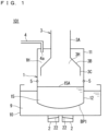
- FIG. 1 and FIG. 2 are each an explanatory diagram schematically illustrating a configuration of an ultrasonic atomization apparatus 101 being a first embodiment of the present invention.
- FIG. 1 illustrates a case at the time of an initial state (No. 1)
- FIG. 2 illustrates a case at the time of generation of a source solution mist MT (No. 2).
- the ultrasonic atomization apparatus 101 includes a container 1, an ultrasonic vibrator 2 being an atomizer, an internal hollow structure body 3, and a gas supply unit 4. Further, as illustrated in FIG. 1 and FIG. 2 , the container 1 has a structure in which an upper cup 11 and a separator cup 12 are coupled together by a connector 5.
- the upper cup 11 may have any shape as long as the upper cup 11 is a container having a space formed inside.
- the upper cup 11 has a substantially cylindrical shape, and in the upper cup 11, a space surrounded by a side surface being formed in a circular shape in plan view is formed.
- the constituent material of the separator cup 12 is polytetrafluoroethylene (PTFE) being one of fluorocarbon resins, whose entire thickness is uniformly 0.5 mm.
- PTFE polytetrafluoroethylene
- the separator cup 12 uses PTFE as its constituent material, and has a bottom surface BP1 having a thickness of 0.5 mm.
- the separator cup 12 has features in that the separator cup 12 satisfies a thin film condition that "the thickness of the bottom surface BP1 is 0.5 mm or less".
- the ultrasonic vibrator 2 applies ultrasonic waves to the source solution 15 in the separator cup 12, and thereby atomizes the source solution 15.
- Four ultrasonic vibrators 2 (only two of them are illustrated in FIG. 1 and FIG. 2 ) are disposed in a bottom surface of a water tank 10. Note that the number of ultrasonic vibrators 2 is not limited to four. One ultrasonic vibrator 2 or two or more ultrasonic vibrators 2 may be provided.
- the internal hollow structure body 3 is a structure body including a hollow in side.
- an opening part is formed, and as illustrated in FIG. 1 and FIG. 2 , the internal hollow structure body 3 is disposed in a manner of being inserted into the upper cup 11 through the opening part.
- a part between the internal hollow structure body 3 and the upper cup 11 is hermetically closed. In other words, the part between the internal hollow structure body 3 and the opening part of the upper cup 11 is sealed.
- the internal hollow structure body 3 For the shape of the internal hollow structure body 3, any shape may be adopted as long as the shape is a shape in which a hollow is formed inside.
- the internal hollow structure body 3 has a flask-like cross-sectional shape without a bottom surface. More specifically, the internal hollow structure body 3 illustrated in FIG. 1 includes a tubular part 3A, a circular truncated cone part 3B, and a cylindrical part 3C.
- the tubular part 3A is a tubular path part having a cylindrical shape, and the tubular part 3A extends from the outside of the upper cup 11 to the inside of the upper cup 11 in a manner of being inserted through the opening part provided in the upper surface of the upper cup 11. More specifically, the tubular part 3A is divided into an upper tubular part disposed on the outside of the upper cup 11 and a lower tubular part disposed on the inside of the upper cup 11.
- the upper tubular part is attached from the outside of the upper surface of the upper cup 11, and the lower tubular part is attached from the inside of the upper surface of the upper cup 11, and in a state in which these are attached together, the upper tubular part and the lower tubular part communicate to each other through the opening part disposed on the upper surface of the upper cup 11.
- One end of the tubular part 3A is connected to, for example, the inside of a thin-film film forming apparatus that forms a thin film by using a source solution mist MT, which is present on the outside of the upper cup 11.
- another end of the tubular part 3A is connected to an upper end side of the circular truncated cone part 3B inside the upper cup 11.
- the circular truncated cone part 3B has its external appearance (side wall surface) of a circular truncated cone shape, and has a hollow being formed inside.
- the circular truncated cone part 3B has its upper surface and bottom surface being opened. In other words, the hollow being formed inside is closed, and there are no upper surface and bottom surface.
- the circular truncated cone part 3B is present in the upper cup 11, and as described above, the upper end side of the circular truncated cone part 3B connects (communicates) to the another end of the tubular part 3A, and a lower end portion side of the circular truncated cone part 3B is connected to the upper end side of the cylindrical part 3C.
- the circular truncated cone part 3B has a cross-sectional shape that is widened toward the end, that is, from the upper end side toward the lower end side.
- the diameter of the side wall on the upper end side of the circular truncated cone part 3B is the smallest (the same as the diameter of the tubular part 3A)
- the diameter of the side wall on the lower end side of the circular truncated cone part 3B is the largest (the same as the diameter of the cylindrical part 3C)
- the diameter of the side wall of the circular truncated cone part 3B is smoothly increased from the upper end side toward the lower end side.
- the cylindrical part 3C is a part having a cylindrical shape, and as described above, the upper end side of the cylindrical part 3C connects (communicates) to the lower end side of the circular truncated cone part 3B, and the lower end side of the cylindrical part 3C faces the bottom surface of the upper cup 11.
- the lower end side of the cylindrical part 3C is released (specifically, does not have a bottom surface).
- a central axis in a direction extending from the tubular part 3A to the cylindrical part 3C through the circular truncated cone part 3B in the internal hollow structure body 3 substantially matches a central axis of the upper cup 11 of the cylindrical shape.
- the internal hollow structure body 3 may be an integral structure, or may be, as illustrated in FIG. 1 and FIG. 2 , configured by combining each member of the upper tubular part constituting a part of the tubular part 3A, the lower tubular part constituting the other part of the tubular part 3A, the circular truncated cone part 3B, and the cylindrical part 3C.
- FIG. 1 and FIG. 2 configured by combining each member of the upper tubular part constituting a part of the tubular part 3A, the lower tubular part constituting the other part of the tubular part 3A, the circular truncated cone part 3B, and the cylindrical part 3C.
- a lower end portion of the upper tubular part is connected to an outer upper surface of the upper cup 11
- an upper end portion of the lower tubular part is connected to an inner upper surface of the upper cup 11
- a member consisting of the circular truncated cone part 3B and the cylindrical part 3C is connected to a lower end portion of the lower tubular part, and the internal hollow structure body 3 consisting of a plurality of members is thereby configured.
- the first space is a hollow part being formed inside the internal hollow structure body 3.
- the hollow part is hereinafter referred to as an "atomization space 3H".
- the atomization space 3H is a space surrounded by the inner side surface of the internal hollow structure body 3.
- the space is a space formed by an inner surface of the upper cup 11 and an outer side surface of the internal hollow structure body 3.
- the space is hereinafter referred to as a "gas supply space 1H".
- the inside of the upper cup 11 is sectioned into the atomization space 3H and the gas supply space 1H.
- the atomization space 3H and the gas supply space 1H are connected through a lower opening part of the cylindrical part 3C.
- the gas supply space 1H is the widest on the upper side of the upper cup 11 and is gradually narrower toward the lower side of the upper cup 11.
- a part of the gas supply space 1H that is surrounded by an outer side surface of the tubular part 3A and an inner side surface of the upper cup 11 is the widest
- a part of the gas supply space 1H that is surrounded by an outer side surface of the cylindrical part 3C and an inner side surface of the upper cup 11 is the narrowest.
- the gas supply unit 4 is disposed in the upper surface of the upper cup 11. Through the gas supply unit 4, a carrier gas G4 for transferring the source solution mist MT (see FIG. 2 ) being atomized by the ultrasonic vibrator 2 to the outside through the tubular part 3A of the internal hollow structure body 3 is supplied.
- a carrier gas G4 for example, a high-concentration inert gas can be adopted.
- the gas supply unit 4 is provided with a supply port 4a, and the carrier gas G4 is supplied into the gas supply space 1H of the container 1 through the supply port 4a present in the container 1.
- the carrier gas G4 supplied from the gas supply unit 4 is supplied into the gas supply space 1H and fills the gas supply space 1H, and is then introduced to the atomization space 3H through the lower opening part of the cylindrical part 3C.
- the separator cup 12 of the container 1 has a cup-like shape, and accommodates the source solution 15 inside.
- the bottom surface BP1 of the separator cup 12 is gently inclined from a side surface part toward the center, and is formed into a spherical surface shape having a predetermined curvature.
- the water tank 10 is filled with ultrasonic wave conveyance water 9, which serves as an ultrasonic wave conveyance medium.
- the ultrasonic wave conveyance water 9 has a function of conveying ultrasonic vibration that is generated from the ultrasonic vibrator 2 disposed in the bottom surface of the water tank 10 to the source solution 15 in the separator cup 12.
- the ultrasonic wave conveyance water 9 is accommodated in the water tank 10 so as to be able to convey, to the inside of the separator cup 12, vibration energy of ultrasonic waves applied from the ultrasonic vibrator 2.
- the source solution 15 to be atomized is accommodated, and a liquid level 15A of the source solution 15 is positioned lower than the position at which the connector 5 is disposed (see FIG. 1 and FIG. 2 ).
- the positions of the separator cup 12 and the water tank 10 are set so that the entire bottom surface BP1 is immersed in the ultrasonic wave conveyance water 9.
- the bottom surface BP1 of the separator cup 12 is disposed above the bottom surface of the water tank 10 without touching the bottom surface of the water tank 10, and the ultrasonic wave conveyance water 9 is present between the bottom surface BP1 of the separator cup 12 and the bottom surface of the water tank 10.
- liquid columns 6 are raised from the liquid level 15A, and the source solution 15 transition to liquid particles and to mist, producing the source solution mist MT in the atomization space 3H.
- the source solution mist MT generated in the gas supply space 1H is supplied to the outside through an upper opening part of the tubular part 3A by the carrier gas G4 supplied from the gas supply unit 4.
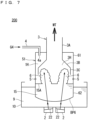
- FIG. 6 and FIG. 7 are each an explanatory diagram schematically illustrating a configuration of a conventional ultrasonic atomization apparatus 200.
- FIG. 6 illustrates a case at the time of an initial state (No. 1)
- FIG. 7 illustrates a case at the time of generation of a source solution mist MT (No. 2).
- a container 51 corresponding to the container 1 of the ultrasonic atomization apparatus 101 is made of a combined structure of an upper cup 61 and a separator cup 62.
- the upper cup 61 is configured similarly to the upper cup 11.
- a conventional separator cup 62 corresponding to the separator cup 12 of the first embodiment adopts polypropylene (PP) that easily transmits ultrasonic waves as its constituent material, whose entire thickness is uniformly 1.0 mm.
- PP polypropylene
- the thickness of the separator cup 62 is set to 1.0 mm.
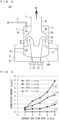
- FIG. 3 is a graph showing effects of the first embodiment.
- the horizontal axis represents a flow rate [L/min] of the carrier gas G4, and the vertical axis represents an atomization amount [g/min] of the generated source solution mist MT.
- FIG. 3 shows experimental results of an experiment performed on the condition that distilled water at 34°C was used as the source solution 15, four ultrasonic vibrators 2, which are models NB-59S-09S-0 manufactured by TDK Corporation, were disposed in the bottom surface of the water tank 10, and vibration frequency of the four ultrasonic vibrators 2 was set to 1.6 MHz. Note that a nitrogen gas is used as the carrier gas G4.
- atomization amount variation L1 shows a case in which the constituent material of the separator cup 12 is PTFE, and film thickness t of the bottom surface BP1 is 0.3 mm.
- Atomization amount variation L2 shows a case in which the constituent material of the separator cup 12 is PTFE, and the film thickness t of the bottom surface BP1 is 0.5 mm.
- Atomization amount variation L3 shows a case in which the constituent material of the separator cup 12 is PTFE, and the film thickness t of the bottom surface BP1 is 0.6 mm.
- the atomization amount variations L1 to L3 are experimental results related to the ultrasonic atomization apparatus 101 according to the first embodiment.
- atomization amount variation L4 shows a case in which the constituent material of the separator cup 62 is PP, and film thickness t of a bottom surface BP6 is 1.0 mm. Specifically, the atomization amount variation L4 is experimental results related to the conventional ultrasonic atomization apparatus 200.
- the film thickness of the bottom surface BP1 is set to 0.5 mm, specifically, when the bottom surface BP1 satisfies the thin film condition described above as shown by the atomization amount variation L2 of FIG. 3 , transmissiveness of ultrasonic waves in the bottom surface BP1 of the separator cup 12 is improved, and the source solution mist MT can be obtained with an effective atomization amount.
- the film thickness of the bottom surface BP1 is set to 0.3 mm as shown by the atomization amount variation L1 of FIG. 3 , transmissiveness of ultrasonic waves in the bottom surface BP1 of the separator cup 12 is significantly improved, and the source solution mist MT can be obtained with an atomization amount that excels the conventional ultrasonic atomization apparatus 200 shown by the atomization amount variation L4.
- the atomization amount of the source solution mist MT reaches a practical level regarding transmissiveness of ultrasonic waves if the film thickness of PTFE adopted as the constituent material of the separator cup 12 was set to 0.5 mm or less.
- the atomization amount of the source solution mist MT reaches a high standard excelling the related art regarding transmissiveness of ultrasonic waves if the film thickness of PTFE adopted as the constituent material of the separator cup 12 was set to 0.3 mm or less.
- transmissiveness of ultrasonic waves is determined by acoustic impedance.
- Acoustic impedance of fluorocarbon resins, including PTFE, is approximately 1.15 [ ⁇ 10 6 kg/m 2 s], and thus it is estimated that results similar to those of the case shown in FIG. 3 can be obtained if fluorocarbon resin is used as the constituent material of the separator cup 12.
- a configuration that the thin film condition regarding the separator cup 12 that "the thickness of the bottom surface BP1 is 0.5 mm or less" is satisfied is referred to as a basic configuration
- a configuration that a limited thin film condition regarding the separator cup 12 that "the thickness of the bottom surface BP1 is 0.3 mm or less" is satisfied is referred to as a limited configuration.
- the thin film condition described above includes the limited thin film condition described above.
- the constituent material of the separator cup 12 in the ultrasonic atomization apparatus 101 according to the first embodiment is PTFE being fluorocarbon resin.
- the fluorocarbon resin as typified by PTFE has properties of having relatively high tolerance to various solvents.
- the separator cup 12 of the ultrasonic atomization apparatus 101 can exert relatively high tolerance to the source solution 15.
- the separator cup 12 having the basic configuration according to the first embodiment enhances transmissiveness of ultrasonic waves in the bottom surface BP1, and can thus generate the source solution mist MT with the atomization amount at the practical level.
- the basic configuration of the ultrasonic atomization apparatus 101 according to the first embodiment produces effects of enabling generation of the source solution mist MT that is excellent in tolerance to the source solution 15 and that has an approximate atomization amount.
- the separator cup 12 having the limited configuration of the ultrasonic atomization apparatus 101 according to the first embodiment can further enhance transmissiveness of ultrasonic waves in the bottom surface BP1 and generate the source solution mist MT with a higher atomization amount.
- FIG. 4 is an explanatory diagram illustrating a cross-sectional structure of a separator cup 12B in an ultrasonic atomization apparatus 102 being a second embodiment of the present invention.
- FIG. 5 is a plan view illustrating a planar structure of the bottom surface BP2 of the separator cup 12B illustrated in FIG. 4 .
- FIG. 5 illustrates a plan view as seen from the bottom surface BP2 side.
- FIG. 4 and FIG. 5 constituent elements similar to those of the ultrasonic atomization apparatus 101 according to the first embodiment are denoted by the same reference signs to omit description thereof as appropriate, and features of the second embodiment will mainly be described.
- the separator cup 12B is different from the separator cup 12 according to the first embodiment in that the bottom surface BP2 does not have a uniform film thickness but has two types of film thicknesses. This will be described below in detail.
- the bottom surface BP2 is separated into four thin film regions R1 each having a relatively small film thickness of 0.5 mm or less, and a thick film region R2 having a relatively large film thickness of larger than 0.5 mm.
- the four thin film regions R1 are set to correspond to the four ultrasonic vibrators 2. Each of the four thin film regions R1 is set in a region including the entire ultrasonic wave transmission region through which the ultrasonic waves applied from a corresponding ultrasonic vibrator 2 transmit. Further, in the bottom surface BP2, the entire region except for the four thin film regions R1 is set to the thick film region R2. Further, the film thickness of the side surface and the upper surface of the separator cup 12 is also set to the same film thickness as the thick film region R2.
- the bottom surface BP2 of the separator cup 12B includes four thin film regions R1 corresponding to the four ultrasonic vibrators 2.
- Each of the four thin film regions R1 includes an ultrasonic wave transmission region that allows transmission of the ultrasonic waves generated from a corresponding ultrasonic vibrator 2 out of the four ultrasonic vibrators 2.
- the separator cup 12B of the ultrasonic atomization apparatus 102 has its thickness ( ⁇ 0.5 mm) of the four thin film regions R1 set smaller than the thickness (> 0.5 mm) of the other region.
- each of the four thin film regions R1 satisfies the thin film condition that "the thickness is 0.5 mm or less" and the thick film region R2 does not satisfy the thin film condition described above.
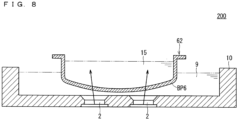
- FIG. 8 is an explanatory diagram illustrating a cross-sectional structure of the conventional ultrasonic atomization apparatus 200.
- FIG. 9 is a plan view illustrating a planar structure of the bottom surface BP6 of the separator cup 62 illustrated in FIG. 8 .
- FIG. 9 illustrates a plan view as seen from the bottom surface BP6 side.
- FIG. 8 and FIG. 9 constituent elements similar to those of the ultrasonic atomization apparatus 200 illustrated in FIG. 6 and FIG. 7 are denoted by the same reference signs to omit description thereof as appropriate.
- the separator cup 62 has a uniform film thickness in the bottom surface BP6 as well. Specifically, the bottom surface BP6 is uniformly set to 1.0 mm. Further, the film thickness of the side surface and the upper surface of the separator cup 62 is also set to the same film thickness (1.0 mm).
- the ultrasonic atomization apparatus 102 has features in that, in the bottom surface BP2 of the separator cup 12B, the four thin film regions R1 (at least one thin film region) satisfy the thin film condition described above, and the thick film region R2 being the other region except for the four thin film regions R1 does not satisfy the thin film condition described above.
- the ultrasonic atomization apparatus 102 owing to the features described above, by setting the film thickness of the thick film region R2 to be relatively large of larger than 0.5 mm in the separator cup 12B, tolerance to the source solution 15 can be enhanced to the maximum.
- the ultrasonic atomization apparatus 102 satisfies the thin film condition that the four thin film regions R1 each including the ultrasonic wave transmission region has a "thickness of 0.5 mm or less", similarly to the ultrasonic atomization apparatus 101 according to the first embodiment.
- the ultrasonic atomization apparatus 102 produces effects of enabling generation of the source solution mist MT with an appropriate atomization amount, similarly to the ultrasonic atomization apparatus 101 according to the first embodiment.
- the source solution mist MT of a higher atomization amount can be generated in the second embodiment as well by setting the thickness of the four thin film regions R1 to 0.3 mm or less so as to achieve satisfaction of the limited thin film condition as in the limited configuration according to the first embodiment.
Landscapes
- Special Spraying Apparatus (AREA)
Priority Applications (1)
| Application Number | Priority Date | Filing Date | Title |
|---|---|---|---|
| EP24204616.7A EP4464419A3 (de) | 2020-01-17 | 2020-01-17 | Ultraschallzerstäubungsvorrichtung |
Applications Claiming Priority (3)
| Application Number | Priority Date | Filing Date | Title |
|---|---|---|---|
| PCT/JP2020/001494 WO2021144959A1 (ja) | 2020-01-17 | 2020-01-17 | 超音波霧化装置 |
| EP20913079.8A EP3912732B1 (de) | 2020-01-17 | 2020-01-17 | Ultraschallzerstäubungsvorrichtung |
| EP24204616.7A EP4464419A3 (de) | 2020-01-17 | 2020-01-17 | Ultraschallzerstäubungsvorrichtung |
Related Parent Applications (2)
| Application Number | Title | Priority Date | Filing Date |
|---|---|---|---|
| EP20913079.8A Division EP3912732B1 (de) | 2020-01-17 | 2020-01-17 | Ultraschallzerstäubungsvorrichtung |
| EP20913079.8A Division-Into EP3912732B1 (de) | 2020-01-17 | 2020-01-17 | Ultraschallzerstäubungsvorrichtung |
Publications (2)
| Publication Number | Publication Date |
|---|---|
| EP4464419A2 true EP4464419A2 (de) | 2024-11-20 |
| EP4464419A3 EP4464419A3 (de) | 2025-02-12 |
Family
ID=76864120
Family Applications (2)
| Application Number | Title | Priority Date | Filing Date |
|---|---|---|---|
| EP20913079.8A Active EP3912732B1 (de) | 2020-01-17 | 2020-01-17 | Ultraschallzerstäubungsvorrichtung |
| EP24204616.7A Pending EP4464419A3 (de) | 2020-01-17 | 2020-01-17 | Ultraschallzerstäubungsvorrichtung |
Family Applications Before (1)
| Application Number | Title | Priority Date | Filing Date |
|---|---|---|---|
| EP20913079.8A Active EP3912732B1 (de) | 2020-01-17 | 2020-01-17 | Ultraschallzerstäubungsvorrichtung |
Country Status (6)
| Country | Link |
|---|---|
| EP (2) | EP3912732B1 (de) |
| JP (1) | JP7086506B2 (de) |
| KR (1) | KR102627895B1 (de) |
| CN (1) | CN113412163A (de) |
| TW (1) | TWI775254B (de) |
| WO (1) | WO2021144959A1 (de) |
Families Citing this family (1)
| Publication number | Priority date | Publication date | Assignee | Title |
|---|---|---|---|---|
| CN118524895A (zh) * | 2022-12-20 | 2024-08-20 | 东芝三菱电机产业系统株式会社 | 超声波雾化装置 |
Citations (1)
| Publication number | Priority date | Publication date | Assignee | Title |
|---|---|---|---|---|
| WO2015019468A1 (ja) | 2013-08-08 | 2015-02-12 | 東芝三菱電機産業システム株式会社 | 霧化装置 |
Family Cites Families (15)
| Publication number | Priority date | Publication date | Assignee | Title |
|---|---|---|---|---|
| JPS5568576U (de) * | 1978-11-01 | 1980-05-12 | ||
| JPS6082164A (ja) * | 1983-10-08 | 1985-05-10 | Omron Tateisi Electronics Co | 超音波霧化装置 |
| JPH0615757U (ja) * | 1992-07-23 | 1994-03-01 | ティーディーケイ株式会社 | 超音波霧化器 |
| JP4289968B2 (ja) | 2003-10-06 | 2009-07-01 | コニシセイコー株式会社 | 携帯用超音波霧化装置 |
| JP4672996B2 (ja) * | 2004-04-19 | 2011-04-20 | 静雄 藤田 | 成膜用霧化装置 |
| JP4079912B2 (ja) * | 2004-06-04 | 2008-04-23 | 松下電器産業株式会社 | 食器洗浄機 |
| JP4774040B2 (ja) * | 2005-03-11 | 2011-09-14 | 明 伴野 | 霧発生装置、および、霧放出演出装置 |
| JP4833765B2 (ja) * | 2005-10-12 | 2011-12-07 | 明 伴野 | 霧発生装置 |
| IL183643A0 (en) * | 2007-06-04 | 2007-10-31 | Shira Inc P D Ltd | Nebulizer particularly useful for converting liquids to fine sprays at extremely low rates |
| JP5603065B2 (ja) * | 2009-01-30 | 2014-10-08 | パナソニックヘルスケア株式会社 | 滅菌物質供給装置およびアイソレータ |
| JP5504120B2 (ja) | 2010-09-30 | 2014-05-28 | パナソニックヘルスケア株式会社 | 過酸化水素水の霧化装置 |
| WO2015115006A1 (ja) * | 2014-01-31 | 2015-08-06 | 株式会社良品計画 | 超音波霧化装置、超音波加湿器、及び、超音波芳香揮散器 |
| JP6680433B2 (ja) | 2015-03-30 | 2020-04-15 | 株式会社Flosfia | 霧化装置および成膜装置 |
| TWI566838B (zh) * | 2016-01-08 | 2017-01-21 | Prec Machinery Research&Development Center | Ultrasonic compound rotary atomization mechanism |
| JP6932237B2 (ja) * | 2018-02-27 | 2021-09-08 | シャープ株式会社 | 霧化装置および調湿装置 |
-
2020
- 2020-01-17 CN CN202080011751.7A patent/CN113412163A/zh active Pending
- 2020-01-17 EP EP20913079.8A patent/EP3912732B1/de active Active
- 2020-01-17 WO PCT/JP2020/001494 patent/WO2021144959A1/ja not_active Ceased
- 2020-01-17 EP EP24204616.7A patent/EP4464419A3/de active Pending
- 2020-01-17 KR KR1020217023824A patent/KR102627895B1/ko active Active
- 2020-01-17 JP JP2021513926A patent/JP7086506B2/ja active Active
- 2020-12-24 TW TW109146004A patent/TWI775254B/zh active
Patent Citations (1)
| Publication number | Priority date | Publication date | Assignee | Title |
|---|---|---|---|---|
| WO2015019468A1 (ja) | 2013-08-08 | 2015-02-12 | 東芝三菱電機産業システム株式会社 | 霧化装置 |
Also Published As
| Publication number | Publication date |
|---|---|
| JP7086506B2 (ja) | 2022-06-20 |
| CN113412163A (zh) | 2021-09-17 |
| EP4464419A3 (de) | 2025-02-12 |
| EP3912732B1 (de) | 2025-07-02 |
| JPWO2021144959A1 (de) | 2021-07-22 |
| KR20210109579A (ko) | 2021-09-06 |
| TW202138067A (zh) | 2021-10-16 |
| US20220111412A1 (en) | 2022-04-14 |
| TWI775254B (zh) | 2022-08-21 |
| KR102627895B1 (ko) | 2024-01-23 |
| EP3912732A4 (de) | 2022-08-31 |
| EP3912732A1 (de) | 2021-11-24 |
| WO2021144959A1 (ja) | 2021-07-22 |
Similar Documents
| Publication | Publication Date | Title |
|---|---|---|
| US10456802B2 (en) | Atomizing apparatus | |
| US4530464A (en) | Ultrasonic liquid ejecting unit and method for making same | |
| EP3912732B1 (de) | Ultraschallzerstäubungsvorrichtung | |
| WO2024151905A3 (en) | Integrated liquid container system and method of assembly thereof | |
| WO2024054969A3 (en) | Integrated liquid container system and method of assembly thereof | |
| JP4850385B2 (ja) | Dlc膜コーティングプラスチック容器の製造装置及びその製造方法 | |
| US12616991B2 (en) | Ultrasonic atomization apparatus | |
| JP2019044770A (ja) | 気体輸送装置 | |
| EP3909689B1 (de) | Ultraschallzerstäubungsvorrichtung | |
| CN110394269A (zh) | 聚焦超声雾化装置 | |
| US10343404B2 (en) | Manufacturing method of fluid control device | |
| CN109424521B (zh) | 气体输送装置 | |
| CN213377476U (zh) | 用于高深宽比深孔结构晶圆或薄胶喷涂晶圆的喷嘴装置 | |
| KR101604757B1 (ko) | 기판 처리 설비용 기화기 | |
| WO2018135666A1 (ja) | 注出具 | |
| HK40052476A (en) | Ultrasonic atomization device | |
| CN106086780B (zh) | 金属化薄膜专用镀膜机的喷油装置 | |
| TWM600659U (zh) | 晶圓表面顆粒清洗噴嘴 | |
| CN211514997U (zh) | 能够在一定水位范围下稳定雾化的装置 | |
| TWI825292B (zh) | 晶圓表面顆粒清洗噴嘴 | |
| JP2019072700A (ja) | 薄膜製造装置 | |
| HK40052524A (en) | Ultrasonic atomizing device | |
| HK40052524B (en) | Ultrasonic atomizing device | |
| CN111570173A (zh) | 喷洒系统 | |
| JPH06275943A (ja) | フラックス塗布装置 |
Legal Events
| Date | Code | Title | Description |
|---|---|---|---|
| PUAI | Public reference made under article 153(3) epc to a published international application that has entered the european phase |
Free format text: ORIGINAL CODE: 0009012 |
|
| STAA | Information on the status of an ep patent application or granted ep patent |
Free format text: STATUS: REQUEST FOR EXAMINATION WAS MADE |
|
| 17P | Request for examination filed |
Effective date: 20241004 |
|
| AC | Divisional application: reference to earlier application |
Ref document number: 3912732 Country of ref document: EP Kind code of ref document: P |
|
| AK | Designated contracting states |
Kind code of ref document: A2 Designated state(s): AL AT BE BG CH CY CZ DE DK EE ES FI FR GB GR HR HU IE IS IT LI LT LU LV MC MK MT NL NO PL PT RO RS SE SI SK SM TR |
|
| RAP3 | Party data changed (applicant data changed or rights of an application transferred) |
Owner name: TMEIC CORPORATION |
|
| REG | Reference to a national code |
Ref country code: DE Ref legal event code: R079 Free format text: PREVIOUS MAIN CLASS: B05B0007000000 Ipc: B05B0017060000 |
|
| PUAL | Search report despatched |
Free format text: ORIGINAL CODE: 0009013 |
|
| AK | Designated contracting states |
Kind code of ref document: A3 Designated state(s): AL AT BE BG CH CY CZ DE DK EE ES FI FR GB GR HR HU IE IS IT LI LT LU LV MC MK MT NL NO PL PT RO RS SE SI SK SM TR |
|
| RIC1 | Information provided on ipc code assigned before grant |
Ipc: B05B 7/00 20060101ALI20250107BHEP Ipc: B05B 17/06 20060101AFI20250107BHEP |