EP3909689B1 - Ultraschallzerstäubungsvorrichtung - Google Patents
Ultraschallzerstäubungsvorrichtung Download PDFInfo
- Publication number
- EP3909689B1 EP3909689B1 EP20913082.2A EP20913082A EP3909689B1 EP 3909689 B1 EP3909689 B1 EP 3909689B1 EP 20913082 A EP20913082 A EP 20913082A EP 3909689 B1 EP3909689 B1 EP 3909689B1
- Authority
- EP
- European Patent Office
- Prior art keywords
- ultrasonic
- water tank
- reflected
- separator cup
- cup
- Prior art date
- Legal status (The legal status is an assumption and is not a legal conclusion. Google has not performed a legal analysis and makes no representation as to the accuracy of the status listed.)
- Active
Links
Images





Classifications
-
- B—PERFORMING OPERATIONS; TRANSPORTING
- B05—SPRAYING OR ATOMISING IN GENERAL; APPLYING FLUENT MATERIALS TO SURFACES, IN GENERAL
- B05B—SPRAYING APPARATUS; ATOMISING APPARATUS; NOZZLES
- B05B17/00—Apparatus for spraying or atomising liquids or other fluent materials, not covered by the preceding groups
- B05B17/04—Apparatus for spraying or atomising liquids or other fluent materials, not covered by the preceding groups operating with special methods
- B05B17/06—Apparatus for spraying or atomising liquids or other fluent materials, not covered by the preceding groups operating with special methods using ultrasonic or other kinds of vibrations
- B05B17/0607—Apparatus for spraying or atomising liquids or other fluent materials, not covered by the preceding groups operating with special methods using ultrasonic or other kinds of vibrations generated by electrical means, e.g. piezoelectric transducers
-
- B—PERFORMING OPERATIONS; TRANSPORTING
- B05—SPRAYING OR ATOMISING IN GENERAL; APPLYING FLUENT MATERIALS TO SURFACES, IN GENERAL
- B05B—SPRAYING APPARATUS; ATOMISING APPARATUS; NOZZLES
- B05B17/00—Apparatus for spraying or atomising liquids or other fluent materials, not covered by the preceding groups
- B05B17/04—Apparatus for spraying or atomising liquids or other fluent materials, not covered by the preceding groups operating with special methods
- B05B17/06—Apparatus for spraying or atomising liquids or other fluent materials, not covered by the preceding groups operating with special methods using ultrasonic or other kinds of vibrations
- B05B17/0607—Apparatus for spraying or atomising liquids or other fluent materials, not covered by the preceding groups operating with special methods using ultrasonic or other kinds of vibrations generated by electrical means, e.g. piezoelectric transducers
- B05B17/0615—Apparatus for spraying or atomising liquids or other fluent materials, not covered by the preceding groups operating with special methods using ultrasonic or other kinds of vibrations generated by electrical means, e.g. piezoelectric transducers spray being produced at the free surface of the liquid or other fluent material in a container and subjected to the vibrations
-
- B—PERFORMING OPERATIONS; TRANSPORTING
- B05—SPRAYING OR ATOMISING IN GENERAL; APPLYING FLUENT MATERIALS TO SURFACES, IN GENERAL
- B05B—SPRAYING APPARATUS; ATOMISING APPARATUS; NOZZLES
- B05B17/00—Apparatus for spraying or atomising liquids or other fluent materials, not covered by the preceding groups
- B05B17/04—Apparatus for spraying or atomising liquids or other fluent materials, not covered by the preceding groups operating with special methods
- B05B17/06—Apparatus for spraying or atomising liquids or other fluent materials, not covered by the preceding groups operating with special methods using ultrasonic or other kinds of vibrations
- B05B17/0607—Apparatus for spraying or atomising liquids or other fluent materials, not covered by the preceding groups operating with special methods using ultrasonic or other kinds of vibrations generated by electrical means, e.g. piezoelectric transducers
- B05B17/0653—Details
-
- B—PERFORMING OPERATIONS; TRANSPORTING
- B05—SPRAYING OR ATOMISING IN GENERAL; APPLYING FLUENT MATERIALS TO SURFACES, IN GENERAL
- B05B—SPRAYING APPARATUS; ATOMISING APPARATUS; NOZZLES
- B05B7/00—Spraying apparatus for discharge of liquids or other fluent materials from two or more sources, e.g. of liquid and air, of powder and gas
- B05B7/0012—Apparatus for achieving spraying before discharge from the apparatus
-
- B—PERFORMING OPERATIONS; TRANSPORTING
- B05—SPRAYING OR ATOMISING IN GENERAL; APPLYING FLUENT MATERIALS TO SURFACES, IN GENERAL
- B05B—SPRAYING APPARATUS; ATOMISING APPARATUS; NOZZLES
- B05B7/00—Spraying apparatus for discharge of liquids or other fluent materials from two or more sources, e.g. of liquid and air, of powder and gas
- B05B7/24—Spraying apparatus for discharge of liquids or other fluent materials from two or more sources, e.g. of liquid and air, of powder and gas with means, e.g. a container, for supplying liquid or other fluent material to a discharge device
- B05B7/2489—Spraying apparatus for discharge of liquids or other fluent materials from two or more sources, e.g. of liquid and air, of powder and gas with means, e.g. a container, for supplying liquid or other fluent material to a discharge device an atomising fluid, e.g. a gas, being supplied to the discharge device
- B05B7/2491—Spraying apparatus for discharge of liquids or other fluent materials from two or more sources, e.g. of liquid and air, of powder and gas with means, e.g. a container, for supplying liquid or other fluent material to a discharge device an atomising fluid, e.g. a gas, being supplied to the discharge device characterised by the means for producing or supplying the atomising fluid, e.g. air hoses, air pumps, gas containers, compressors, fans, ventilators, their drives
Definitions
- the present invention relates to an ultrasonic atomization apparatus that atomizes a source solution into fine mist by using an ultrasonic vibrator and transfers the mist to the outside.
- an ultrasonic atomization apparatus In a field of manufacturing electronic devices, an ultrasonic atomization apparatus is used in some cases. In the field of the electronic device manufacturing, the ultrasonic atomization apparatus atomizes a solution by using ultrasonic waves that are oscillated from an ultrasonic vibrator, and sends out the atomized solution to the outside by using transfer gas. When the source solution mist transferred to the outside is sprayed onto a substrate, a thin film for the electronic device is formed on the substrate.
- a double chamber method in which the source solution and the ultrasonic vibrator do not come into contact with each other, is used.
- a separator cup for accommodating the source solution is used separately for a water tank provided with the ultrasonic vibrator in its bottom surface. The separator cup is required to allow transmission of ultrasonic waves; however, a part of the ultrasonic waves is reflected. Note that an ultrasonic wave conveyance solvent is accommodated in the water tank.
- ultrasonic atomization apparatus employing the double chamber method described above is an atomization apparatus disclosed in WO 2015/019468 A1 .
- JP S55 68576 U JP S60 82164 A
- JP 2002 326045 A JP 2008 100204 A
- WO 2010/044368 A1 JP S60 82164 A discloses an ultrasonic atomization apparatus as specified in the preamble of claims 1 and 2.
- constituent materials having the same acoustic impedance need to be used as the constituent materials of the ultrasonic wave conveyance solvent and the separator (the bottom surface thereof).
- the acoustic impedances of both of the constituent materials completely match each other, and reflected waves are inevitably generated.
- the reflected waves are radiated toward the bottom surface side of the water tank.
- the water tank (the bottom surface thereof) may be melted or the ultrasonic vibrator provided in the bottom surface of the water tank may have a failure, which is a cause of reducing the life of the ultrasonic atomization apparatus.
- a conventional ultrasonic atomization apparatus has poor durability.
- the present invention has an object to solve the problem as described above and provide an ultrasonic atomization apparatus with enhanced durability.
- An ultrasonic atomization apparatus includes the features specified in claim 1.
- An ultrasonic atomization apparatus includes the features specified in claim 2.
- the separator cup and the plurality of ultrasonic vibrators are provided to satisfy the reflected wave avoidance condition and the plurality of ultrasonic wave absorption members or ultrasonic wave reflection members are provided in the plurality of reflected wave reception regions.
- FIG. 1 is an explanatory diagram schematically illustrating a configuration of an ultrasonic atomization apparatus 101 being a first embodiment not encompassed by the wording of the claims but useful for understanding the invention.
- the ultrasonic atomization apparatus 101 includes a container 1, an ultrasonic vibrator 2 being an atomizer, an internal hollow structure body 3, and a gas supply unit 4.
- the container 1 has a structure in which an upper cup 11 and a separator cup 12 are coupled together by a connector 5.
- the ultrasonic vibrator 2 includes an ultrasonic vibration plate 22 as its main component.
- the upper cup 11 may have any shape as long as the upper cup 11 is a container having a space formed inside.
- the upper cup 11 has a substantially cylindrical shape, and in the upper cup 11, a space surrounded by a side surface being formed in a circular shape in plan view is formed. Meanwhile, in the separator cup 12, a source solution 15 is accommodated.
- the ultrasonic vibrator 2 applies ultrasonic waves to the source solution 15 in the separator cup 12 from the internal ultrasonic vibration plate 22, and thereby atomizes the source solution 15.
- Four ultrasonic vibrators 2 (only two of them are illustrated in FIG. 1 ) are disposed in a bottom surface of a water tank 10. Although only schematically illustrated in FIG. 1 , the upper side of the ultrasonic vibrator 2 is opened. Note that the number of ultrasonic vibrators 2 is not limited to four. One ultrasonic vibrator 2 or two or more ultrasonic vibrators 2 may be provided.
- the internal hollow structure body 3 is a structure body including a hollow in side.
- an opening part is formed, and as illustrated in FIG. 1 , the internal hollow structure body 3 is disposed in a manner of being inserted in to the upper cup 11 through the opening part.
- a part between the internal hollow structure body 3 and the upper cup 11 is hermetically closed. In other words, the part between the internal hollow structure body 3 and the opening part of the upper cup 11 is sealed.
- the internal hollow structure body 3 For the shape of the internal hollow structure body 3, any shape may be adopted as long as the shape is a shape in which a hollow is formed inside.
- the internal hollow structure body 3 has a flask-like cross-sectional shape without a bottom surface. More specifically, the internal hollow structure body 3 illustrated in FIG. 1 includes a tubular part 3A, a circular truncated cone part 3B, and a cylindrical part 3C.
- the tubular part 3A is a tubular path part having a cylindrical shape, and the tubular part 3A extends from the outside of the upper cup 11 to the inside of the upper cup 11 in a manner of being inserted through the opening part provided in the upper surface of the upper cup 11. More specifically, the tubular part 3A is divided into an upper tubular part disposed on the outside of the upper cup 11 and a lower tubular part disposed on the inside of the upper cup 11.
- the upper tubular part is attached from the outside of the upper surface of the upper cup 11, and the lower tubular part is attached from the inside of the upper surface of the upper cup 11, and in a state in which these are attached together, the upper tubular part and the lower tubular part communicate to each other through the opening part disposed on the upper surface of the upper cup 11.
- One end of the tubular part 3A is connected to, for example, the inside of a thin-film film forming apparatus that forms a thin film by using a source solution mist MT, which is present on the outside of the upper cup 11.
- another end of the tubular part 3A is connected to an upper end side of the circular truncated cone part 3B inside the upper cup 11.
- the circular truncated cone part 3B has its external appearance (side wall surface) of a circular truncated cone shape, and has a hollow being formed inside.
- the circular truncated cone part 3B has its upper surface and bottom surface being opened. In other words, the hollow being formed inside is closed, and there are no upper surface and bottom surface.
- the circular truncated cone part 3B is present in the upper cup 11, and as described above, the upper end side of the circular truncated cone part 3B connects (communicates) to the another end of the tubular part 3A, and a lower end portion side of the circular truncated cone part 3B is connected to the upper end side of the cylindrical part 3C.
- the circular truncated cone part 3B has a cross-sectional shape that is widened toward the end, that is, from the upper end side toward the lower end side.
- the diameter of the side wall on the upper end side of the circular truncated cone part 3B is the smallest (the same as the diameter of the tubular part 3A)
- the diameter of the side wall on the lower end side of the circular truncated cone part 3B is the largest (the same as the diameter of the cylindrical part 3C)
- the diameter of the side wall of the circular truncated cone part 3B is smoothly increased from the upper end side toward the lower end side.
- the cylindrical part 3C is a part having a cylindrical shape, and as described above, the upper end side of the cylindrical part 3C connects (communicates) to the lower end side of the circular truncated cone part 3B, and the lower end side of the cylindrical part 3C faces the bottom surface of the upper cup 11.
- the lower end side of the cylindrical part 3C is opened (specifically, does not have a bottom surface).
- central axis in a direction extending from the tubular part 3A to the cylindrical part 3C through the circular truncated cone part 3B in the internal hollow structure body 3 substantially matches a central axis of the upper cup 11 of the cylindrical shape.
- the internal hollow structure body 3 may be an integral structure, or may be, as illustrated in FIG. 1 , configured by combining each member of the upper tubular part constituting a part of the tubular part 3A, the lower tubular part constituting the other part of the tubular part 3A, the circular truncated cone part 3B, and the cylindrical part 3C.
- a lower end portion of the upper tubular part is connected to an outer upper surface of the upper cup 11
- an upper end portion of the lower tubular part is connected to an inner upper surface of the upper cup 11
- a member consisting of the circular truncated cone part 3B and the cylindrical part 3C is connected to a lower end portion of the lower tubular part, and the internal hollow structure body 3 consisting of a plurality of members is thereby configured.
- the first space is a hollow part being formed inside the internal hollow structure body 3.
- the hollow part is hereinafter referred to as an "atomization space 3H".
- the atomization space 3H is a space surrounded by the inner side surface of the internal hollow structure body 3.
- the space is a space formed by an inner surface of the upper cup 11 and an outer side surface of the internal hollow structure body 3.
- the space is hereinafter referred to as a "gas supply space 1H".
- the inside of the upper cup 11 is sectioned into the atomization space 3H and the gas supply space 1H.
- the atomization space 3H and the gas supply space 1H are connected through a lower opening part of the cylindrical part 3C.
- the gas supply space 1H is the widest on the upper side of the upper cup 11 and is gradually narrower toward the lower side of the upper cup 11.
- a part of the gas supply space 1H that is surrounded by an outer side surface of the tubular part 3A and an inner side surface of the upper cup 11 is the widest
- a part of the gas supply space 1H that is surrounded by an outer side surface of the cylindrical part 3C and an inner side surface of the upper cup 11 is the narrowest.
- the gas supply unit 4 is disposed in the upper surface of the upper cup 11. Through the gas supply unit 4, a carrier gas G4 for transferring the source solution mist MT (see FIG. 1 ) being atomized by the ultrasonic vibrator 2 to the outside through the tubular part 3A of the internal hollow structure body 3 is supplied.
- a carrier gas G4 for example, a high-concentration inert gas can be adopted.
- the gas supply unit 4 is provided with a supply port 4a, and the carrier gas G4 is supplied into the gas supply space 1H of the container 1 through the supply port 4a present in the container 1.
- the carrier gas G4 supplied from the gas supply unit 4 is supplied into the gas supply space 1H and fills the gas supply space 1H, and is then introduced to the atomization space 3H through the lower opening part of the cylindrical part 3C.
- the separator cup 12 of the container 1 has a cup-like shape, and accommodates the source solution 15 inside.
- a bottom surface BP1 of the separator cup 12 is inclined from a side surface part toward the center, and is formed into a spherical surface shape having a set curvature K1 other than "0".
- the bottom surface BP1 of the separator cup 12 is formed into a spherical surface shape with the center projecting downward, which is defined by the set curvature K1.
- One of the purposes for forming the bottom surface BP1 of the separator cup 12 into the spherical surface shape is an air bubble retention prevention purpose of preventing air bubbles of the source solution 15 from remaining near the bottom surface BP1 when the source solution mist MT is generated.
- the water tank 10 is filled with ultrasonic wave conveyance water 9, which serves as an ultrasonic wave conveyance medium.
- the ultrasonic wave conveyance water 9 has a function of conveying ultrasonic vibration that is generated from the ultrasonic vibration plate 22 of the ultrasonic vibrator 2 disposed in the bottom surface of the water tank 10 to the source solution 15 in the separator cup 12.
- the ultrasonic wave conveyance water 9 is accommodated in the water tank 10 so as to be able to convey, to the inside of the separator cup 12, vibration energy of ultrasonic waves (incident wave W1 thereof) applied from the ultrasonic vibrator 2.
- the source solution 15 to be atomized is accommodated, and a liquid level 15A of the source solution 15 is positioned lower than the position at which the connector 5 is disposed (see FIG. 1 ).
- the positions of the separator cup 12 and the water tank 10 are set so that the entire bottom surface BP1 is immersed in the ultrasonic wave conveyance water 9.
- the bottom surface BP1 of the separator cup 12 is disposed above the bottom surface of the water tank 10 without touching the bottom surface of the water tank 10, and the ultrasonic wave conveyance water 9 is present between the bottom surface BP1 of the separator cup 12 and the bottom surface of the water tank 10.
- the source solution mist MT generated in the gas supply space 1H is supplied to the outside through an upper opening part of the tubular part 3A by the carrier gas G4 supplied from the gas supply unit 4.
- the ultrasonic atomization apparatus 101 of the first embodiment when a part of the four incident waves (at least one incident wave; a plurality of incident waves) transmitted from the four ultrasonic vibrators 2 (at least one ultrasonic vibrator) is reflected on the bottom surface of the bottom surface BP1 of the separator cup 12, four reflected waves W2 (at least one bottom surface-reflected wave) are obtained.
- the separator cup 12 and the four ultrasonic vibrators 2 of the ultrasonic atomization apparatus 101 are provided so as to satisfy the following reflected wave avoidance condition.
- the reflected wave avoidance condition is a condition that "the four reflected waves W2 are not received by any of the four ultrasonic vibrators 2". Note that, here, "not received” means that the four ultrasonic vibrators 2 are not disposed in a propagation path of the four reflected waves W2. In the following, the reflected wave avoidance condition will be described in detail.
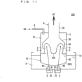
- FIG. 11 is an explanatory diagram schematically illustrating a configuration of a conventional ultrasonic atomization apparatus 200.
- parts similar to those of the ultrasonic atomization apparatus 101 of the first embodiment are denoted by the same reference signs and general description thereof will be omitted.
- a bottom surface BP6 of the separator cup 62 of the container 51 is gently inclined from the side surface part toward the center, and is formed into a spherical surface shape defined by a set curvature K6 ( ⁇ K1).
- the set curvature K6 is set to a relatively small value to the extent of allowing the air bubble retention prevention purpose to be achieved.
- the conventional ultrasonic atomization apparatus 200 when a part of the four incident waves transmitted from the four ultrasonic vibrators 2 is reflected on the bottom surface of the bottom surface BP6 of the separator cup 62, the four reflected waves W2 are obtained.
- the set curvature K6 of the bottom surface BP6 of the separator cup 62 is considerably smaller than the set curvature K1, and the four ultrasonic vibrators 2 are closely disposed so as to be relatively close to the center of the bottom surface of the water tank 10. The reason why the four ultrasonic vibrators 2 are closely disposed as described above is to cause the four incident waves W1 to securely reach the source solution 15 in the separator cup 62.
- the separator cup 62 and the four ultrasonic vibrators 2 of the ultrasonic atomization apparatus 200 fail to satisfy the reflected wave avoidance condition unlike the first embodiment.
- the four reflected waves W2 are securely received by the four ultrasonic vibrators 2. This is because the angle of reflection of the reflected waves W2 (angle of incidence of the incident waves W1) is inevitably small due to the shape of the bottom surface BP6 of the separator cup 62 and the disposition state of the four ultrasonic vibrators 2.
- each of the incident waves W1 and the reflected waves W2 to W4 illustrated in FIG. 1 and FIG. 11 described above and the figures to be described later is schematically illustrated.
- the area of the ultrasonic vibration plate 22 to be described later in detail corresponds to an ultrasonic wave output size.
- the ultrasonic wave output from the center point of the ultrasonic vibration plate 22 is schematically illustrated with arrows.
- each of the incident waves W1 and the reflected waves W2 to W4 of the ultrasonic waves has rectilinear propagation property, and is beam-like.
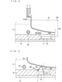
- FIG. 2 and FIG. 3 are each an explanatory diagram illustrating details of a surrounding structure of one ultrasonic vibrator 2.
- the ultrasonic vibrator 2 is provided in a state of being embedded into the bottom surface of the water tank 10.
- An open region OP2 is provided above the ultrasonic vibrator 2.
- setting is made to a liquid level height H15 from the ultrasonic vibration plate 22 to the liquid level 15A of the source solution 15.
- the liquid level height H15 is height from the center of the ultrasonic vibration plate 22 to the liquid level 15A.
- a cooling pipe 29 allows cooling water to flow inside in order to cool the ultrasonic wave conveyance water 9.
- the ultrasonic vibration plate 22 of the ultrasonic vibrator 2 has a disk-like shape having an outer diameter of approximately 20 mm, and ultrasonic waves of the same size as the disk-like ultrasonic vibration plate 22 are generated due to vibration of the ultrasonic vibration plate 22.
- the ultrasonic waves have high directivity, and travel without spreading within a near field length DL and spread at a certain angle beyond the near field length DL. Note that the near field length DL can be calculated according to the following equation (1).
- DL ED 2 / ⁇ ⁇ ⁇ / 4
- ED represents the outer diameter of the ultrasonic vibration plate 22
- ⁇ represents speed of sound (1500 m/sec in water).
- the atomization amount of the source solution mist MT can be brought to the maximum level when the liquid level height H15 is set to 30 to 40 mm.
- the distance between the bottom surface BP1 (BP6) of the separator cup 12 (62) and the ultrasonic vibration plate 22 of the ultrasonic vibrator 2 is inevitably reduced.
- FIG. 4 is an explanatory diagram schematically illustrating a curvature radius r6 of the bottom surface BP6 of the conventional separator cup 62.
- setting is made to the same distance D6 from a center point C10 (reference point) of the bottom surface of the water tank 10 to a center position of the ultrasonic vibration plate 22 of each of the four ultrasonic vibrators 2.
- the distance D6 is relatively short.
- the conventional ultrasonic atomization apparatus 200 satisfies the reflected wave avoidance condition.
- the reflected wave avoidance condition is not taken into consideration, and the set curvature K6 of the bottom surface BP6 of the separator cup 62 in consideration of the air bubble retention prevention purpose need not be set large.
- the set curvature K6 is set large, there is a negative element that the amount of the source solution 15 accommodated in the separator cup 62 is reduced due to the restriction of the liquid level height H15, and thus it is desirable that the set curvature K6 be set small within the range of satisfying the air bubble retention prevention purpose.
- the reflected waves W2 are invariably received in a partial region RS of the ultrasonic vibrator 2.
- FIG. 5 is an explanatory diagram illustrating a curvature radius r1 of the bottom surface BP1 of the separator cup 12 and a disposition state of the ultrasonic vibrators 2.
- the four ultrasonic vibrators 2 are disposed at positions relatively close to the center part of the bottom surface BP1 in plan view.
- the angle of reflection of the reflected waves W2 (angle of incidence of the incident waves W1) cannot be increased, which may still hinder satisfaction of the reflected wave avoidance condition.
- the reflected waves W2 obtained when the incident waves W1 of each ultrasonic vibrator 2 (ultrasonic vibration plate 22) are reflected on the bottom surface BP1 may be received in the ultrasonic vibrators 2.
- the reflected wave avoidance condition can be satisfied by setting to a curvature radius rx that is even shorter than the curvature radius r1 illustrated in FIG. 5 and setting the set curvature Kx defining the spherical surface of the bottom surface BP1 to be larger than the set curvature K1.
- FIG. 6 is an explanatory diagram illustrating the curvature radius r1 of the bottom surface BP1 of the separator cup 12 of the first embodiment and the disposition state of the ultrasonic vibrators 2.
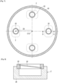
- FIG. 7 is a plan view illustrating a disposition state of the four ultrasonic vibrators 2 in the bottom surface of the water tank 10. In FIG. 7 , the planar shape of the bottom surface of the water tank 10 exhibits a circular configuration. Note that the hatched region denotes the side surface of the water tank 10.
- the cross-sectional shape of the bottom surface BP1 is formed into an arc shape having a relatively short curvature radius r1 with respect to the imaginary center point C1, and the set curvature K1 is sufficiently large as compared to the set curvature K6.
- the four ultrasonic vibrators 2 are disposed such that the four ultrasonic vibration plates 22 are located to be annularly spaced apart at regular intervals (intervals of 90 degrees) along outer circumference of a distance D1 (> D6) about the center point C10 being a reference point.
- the four ultrasonic vibrators 2 are disposed to be separated apart from each other so as to have the same distance D1 from the center point C10 being a reference point of the bottom surface of the water tank 10.
- the distance D1 from the center point C10 of the bottom surface of the water tank 10 is set to be longer than the conventional distance D6.
- each of the four ultrasonic vibration plates 22 is made far from the center point C10, and the intervals of the four ultrasonic vibrators 2 are also sufficiently large.
- FIG. 8 is a cross-sectional diagram of the ultrasonic vibrator 2 illustrating the A-A cross-section of FIG. 7 .
- the ultrasonic vibration plate 22 in the ultrasonic vibrator 2 is fixed to be slightly inclined due to a support rubber 23 that is provided on an upper portion of a base 24. Specifically, the inclination is approximately 7 degrees with respect to the bottom surface of the water tank 10.
- the ultrasonic vibration plate 22 of each ultrasonic vibrator 2 is slightly inclined toward a direction away from the center point C10. In this manner, the four ultrasonic vibration plates 22 have a predetermined angle, other than "0", with respect to the bottom surface of the water tank 10.
- the first embodiment provides technical improvement that the set curvature K1 of the bottom surface BP1 of the separator cup 12 is set larger than the conventional set curvature K6, and the distance D1 from the center point C10 of the bottom surface of the water tank 10 of each of the four ultrasonic vibrators 2 (ultrasonic vibration plates 22) is set longer than the conventional distance D6.
- the set curvature K1 of the bottom surface BP1 and the distance D1 from the center point C10 of the four ultrasonic vibration plates 22 can be set so that the reflected wave avoidance condition is satisfied.
- the angle of reflection of the reflected waves W2 (angle of incidence of the incident waves W1) can be made larger than the conventional technology, with the result that the effect that the reflected waves W2 are not received in the ultrasonic vibrators 2 can be achieved.
- FIG. 6 illustrates the incident wave W1 and the reflected wave W2 related to one ultrasonic vibrator 2
- the reflected waves W2 are not received in the other three ultrasonic vibrators 2 as well. The reason therefor is as follows.
- Each of the four ultrasonic vibrators 2 is disposed at the same distance D1 from the center point C10, and the inclination of the four ultrasonic vibration plates 22 is also inclined at approximately 7 degrees toward a direction away from the center point C10 in common.
- the angle of incidence of the incident waves W1 (angle of reflection of the reflected waves W2) with respect to the bottom surface BP1 of the separator cup 12 is the same.
- the four reflected waves W2 are not received in the four ultrasonic vibrators 2 (ultrasonic vibration plates 22).
- the separator cup 12 and the four ultrasonic vibrators 2 are set so as to satisfy the reflected wave avoidance condition.
- the bottom surface BP1 of the separator cup 12 is set to the set curvature K1 (> K6), and is set to the distance D1 (> D6) from the center point C10 of the bottom surface of the water tank 10 of each of the four ultrasonic vibrators 2.
- the bottom surface BP1 of the separator cup 12 is formed into a spherical surface shape with the center projecting downward.
- each of the four ultrasonic vibrators 2 is disposed to be separated apart from each other so as to have the same distance D1 from the center point C 10 of the bottom surface of the water tank 10 with respect to the separator cup 12 having the bottom surface BP1 in which the spherical surface is defined by the set curvature K1.
- the reflected wave avoidance condition can be satisfied.
- FIG. 9 is an explanatory diagram schematically illustrating a configuration of an ultrasonic atomization apparatus 102 being a second embodiment of the present invention.
- constituent parts similar to those of the ultrasonic atomization apparatus 101 of the first embodiment are denoted by the same reference signs and description thereof is omitted as appropriate, and features of the second embodiment will be mainly described.
- ultrasonic wave absorption members 25 are provided on a surface of the bottom surface of a water tank 10B, so as to correspond to the four reflected waves W2.
- the four ultrasonic wave absorption members 25 are embedded in a part of the bottom surface of the water tank 10B so as to form a surface region of the water tank 10B.
- the difference between the water tank 10B of the second embodiment and the water tank 10 of the first embodiment lies in presence or absence of the four ultrasonic wave absorption members 25.
- the four ultrasonic wave absorption members 25 are provided in four reflected wave reception regions that receive the four reflected waves W2 in the bottom surface of the water tank 10B.
- the bottom surface of the water tank 10B has predetermined thickness.
- a recess portion is provided in an upper portion of each of the four reflected wave reception regions, and the ultrasonic wave absorption member 25 is embedded in each recess portion.
- the four reflected wave reception regions can be recognized in advance from the disposition of the four ultrasonic vibrators 2 (ultrasonic vibration plates 22), the inclination of the ultrasonic vibration plates 22, the set curvature K1 defining the spherical surface of the bottom surface BP1 of the separator cup 12, and the like.
- the ultrasonic atomization apparatus 102 of the second embodiment can have higher durability than that of the first embodiment.
- the four ultrasonic wave reflection members 32 are provided in the four reflected wave reception regions that receive the four reflected waves W2 in the bottom surface of the water tank 10C.
- a recess portion is provided in an upper portion of each of the four reflected wave reception regions, and the ultrasonic wave reflection member 32 is embedded in each recess portion.
- the basic configuration of the ultrasonic atomization apparatus 103 of the third embodiment has features in that the four ultrasonic wave reflection members 32 (a plurality of ultrasonic wave reflection members) are provided in the four reflected wave reception regions (a plurality of reflected wave reception regions) in the bottom surface of the water tank 10C.
- a constituent material of the ultrasonic wave reflection member 32 include stainless steel, copper, and the like.
- the basic configuration of the ultrasonic atomization apparatus 103 of the third embodiment can have durability higher than that of the first embodiment.
- Surfaces of the four ultrasonic wave reflection members 32 of the third embodiment have a predetermined angle, other than "0", with respect to the bottom surface of the water tank 10C, and are specifically inclined to a direction of the center point C10 of the bottom surface of the water tank 10.
- the predetermined angle of the surfaces of the ultrasonic wave reflection members 32 is set such that the four secondary reflected waves W3 enter the source solution 15 as secondary transmission waves W31 through the bottom surface BP1 of the separator cup 12.
- the basic configuration of the four ultrasonic wave reflection members 32 of the third embodiment has the predetermined angle, other than "0", with respect to the bottom surface of the water tank 10C, and can thus securely cause a part of the four secondary reflected waves W to enter the source solution 15 as the secondary transmission waves W31 by adjusting the predetermined angle.
- the ultrasonic atomization apparatus 103 of the third embodiment allows the four secondary transmission waves W31 generated by the four secondary reflected waves W3 to enter the source solution 15 in addition to the four transmission waves W11 generated by the four incident waves W1, and thus exerts an atomization amount increase effect that the atomization amount of the source solution mist MT to be generated can be increased accordingly.
- ultrasonic wave absorption members 27 are provided on a surface of the bottom surface of the water tank 10C, so as to correspond to the four tertiary reflected waves W4.
- the four ultrasonic wave absorption members 27 are embedded in a part of the bottom surface of the water tank 10C so as to form a surface region of the water tank 10C.
- the difference between the water tank 10C of the modification of the third embodiment and the water tank 10 of the first embodiment lies in presence or absence of the four ultrasonic wave reflection members 32 and the four ultrasonic wave absorption members 27.
- possible examples of a constituent material of the ultrasonic wave absorption member 27 include constituent materials similar to those of the ultrasonic wave absorption member 25 of the second embodiment.
- the four ultrasonic wave absorption members 27 are provided in four tertiary reflected wave reception regions that receive the four tertiary reflected waves W4 in the bottom surface of the water tank 10C.
- a recess portion is provided in an upper portion of each of the four tertiary reflected wave reception regions, and the ultrasonic wave absorption member 27 is embedded in each recess portion.
- the modification of the ultrasonic atomization apparatus 103 of the third embodiment has features in that the four ultrasonic wave absorption members 27 (a plurality of ultrasonic wave reflection members) are further provided in the four tertiary reflected wave reception regions (a plurality of tertiary reflected wave reception regions) in the bottom surface of the water tank 10C.
- the modification of the third embodiment described above can securely avoid a phenomenon in which the four tertiary reflected waves W4 (a plurality of tertiary reflected waves) enter the bottom surface of the water tank 10C other than the four ultrasonic wave absorption members 27, and can protect the bottom surface of the water tank 10C.
- the modification of the ultrasonic atomization apparatus 103 of the third embodiment can have durability higher than that of the basic configuration of the third embodiment.
- the constituent material of the separator cup 12 of each of the first embodiment to the third embodiment polypropylene (PP), which easily transmits ultrasonic waves, is generally adopted.
- PP polypropylene
- fluorocarbon resin as typified by PTFE may be adopted.
- the separator cup 12 may have the bottom surface BP1 whose constituent material is fluorocarbon resin.
- the fluorocarbon resin is inferior to PP in transmissiveness of ultrasonic waves.
- the thickness of the bottom surface BP1 it is conceivable to set the thickness of the bottom surface BP1 to 0.5 mm or less, desirably 0.3 mm or less.
- the ultrasonic atomization apparatus 103 of the third embodiment having the four ultrasonic wave reflection members 32 has the atomization amount increase effect, and can accordingly improve the inferiority of the fluorocarbon resin in transmissiveness of ultrasonic waves.
Landscapes
- Special Spraying Apparatus (AREA)
- Pressure-Spray And Ultrasonic-Wave- Spray Burners (AREA)
Claims (4)
- Ultraschallzerstäubungsvorrichtung mit:einem Behälter, der in einem unteren Teil eine Trennschale (12) aufweist, die konfiguriert ist, eine Quellenlösung (15) aufzunehmen;einem innen hohlen Strukturkörper (3) mit einem Hohlraum innen, der in dem Behälter oberhalb der Trennschale vorgesehen ist;einem Wassertank (10B), der innen ein Ultraschallübertragungsmedium (9) enthält, wobei der Wassertank und die Trennschale so positioniert sind, dass eine Bodenfläche (BP1) der Trennschale in dem Ultraschallübertragungsmedium eingetaucht ist; undeiner Vielzahl von Ultraschallvibratoren (2), die in einer Bodenfläche des Wassertanks vorgesehen sind, wobeiwenn Teile einer Vielzahl von auftreffenden Wellen, die von der Vielzahl von Ultraschallvibratoren ausgestrahlt werden, auf der Bodenfläche der Trennschale reflektiert werden, eine Vielzahl von Bodenflächenreflexionswellen (W2) erhalten wird,die Trennschale und die Vielzahl von Ultraschallvibratoren so vorgesehen sind, dass sie eine Reflexionswellenvermeidungsbedingung erfüllen,die Reflexionswellenvermeidungsbedingung eine Bedingung ist, dass "die Vielzahl von Ultraschallvibratoren nicht in einem Ausbreitungsweg der Vielzahl der Bodenflächenreflexionswellen angeordnet sind",die Bodenfläche der Trennschale zu einer Kugelflächenform mit einem nach unten ragenden Zentrum ausgebildet ist,die Vielzahl von Ultraschallvibratoren so voneinander getrennt angeordnet sind, dass sie von einem Bezugspunkt (C10) der Bodenfläche des Wassertanks aus einen gleichen Abstand (D1) haben,die Bodenfläche des Wassertanks eine Vielzahl von Reflexionswellenaufnahmebereichen aufweist, die so konfiguriert sind, dass sie die Vielzahl von Bodenflächenreflexionswellen aufnehmen, unddie Vielzahl von Reflexionswellenaufnahmebereichen von den Bereichen, in denen die Vielzahl von Ultraschallvibratoren vorgesehen sind, verschieden sind,dadurch gekennzeichnet, dassdie Ultraschallzerstäubungsvorrichtung außerdem eine Vielzahl von Ultraschallwellenabsorptionselementen (25) umfasst, die in der Vielzahl von Reflexionswellenaufnahmebereichen vorgesehen sind, wobei ein konstituierendes Material der Vielzahl von Ultraschallwellenabsorptionselementen mindestens eines von Urethankautschuk, Silikonkautschuk, Fluorkohlenstoffkautschuk, Ethylen-Propylen-Kautschuk, Butylkautschuk und Ethylenkautschuk umfasst.
- Ultraschallzerstäubungsvorrichtung mit:einem Behälter (1), der in einem unteren Teil eine Trennschale (12) aufweist, die konfiguriert ist, eine Quellenlösung (15) aufzunehmen;einem innen hohlen Strukturkörper (3) mit einem Hohlraum innen, der in dem Behälter oberhalb der Trennschale vorgesehen ist;einem Wassertank (10C), der innen ein Ultraschallübertragungsmedium enthält, wobei der Wassertank und die Trennschale so positioniert sind, dass eine Bodenfläche der Trennschale in dem Ultraschallübertragungsmedium eingetaucht ist; undeiner Vielzahl von Ultraschallvibratoren (2), die in einer Bodenfläche des Wassertanks vorgesehen sind, wobeiwenn Teile einer Vielzahl von auftreffenden Wellen, die von der Vielzahl von Ultraschallvibratoren ausgestrahlt werden, auf der Bodenfläche der Trennschale reflektiert werden, eine Vielzahl von Bodenflächenreflexionswellen erhalten wird,die Trennschale und die Vielzahl von Ultraschallvibratoren so vorgesehen sind, dass sie eine Reflexionswellenvermeidungsbedingung erfüllen,die Reflexionswellenvermeidungsbedingung eine Bedingung ist, dass "die Vielzahl von Ultraschallseparatoren nicht in einem Ausbreitungsweg der Vielzahl von Bodenflächenreflexionswellen angeordnet sind",die Bodenfläche der Trennschale zu einer Kugelflächenform mit einem nach unten ragenden Zentrum ausgebildet ist,die Vielzahl von Ultraschallvibratoren so voneinander getrennt angeordnet sind, dass sie von einem Bezugspunkt der Bodenfläche des Wassertanks aus einen gleichen Abstand haben,die Bodenfläche des Wassertanks eine Vielzahl von Reflexionswellenaufnahmebereichen aufweist, die so konfiguriert sind, dass sie die Vielzahl von Bodenflächenreflexionswellen aufnehmen, unddie Vielzahl von Reflexionswellenaufnahmebereichen von den Bereichen, in denen die Vielzahl von Ultraschallvibratoren vorgesehen sind, verschieden sind,dadurch gekennzeichnet, dassdie Ultraschallzerstäubungsvorrichtung außerdem eine Vielzahl von Ultraschallreflexionselementen (32) umfasst, die in der Vielzahl von Reflexionswellenaufnahmebereichen vorgesehen sind, wobei ein konstituierendes Material der Vielzahl von Ultraschallwellenreflexionselementen rostfreier Stahl oder Kupfer ist.
- Ultraschallzerstäubungsvorrichtung nach Anspruch 2, wobeiwenn die Vielzahl von Bodenflächenreflexionswellen durch die Vielzahl von Ultraschallwellenreflexionselementen reflektiert werden, eine Vielzahl von Sekundärreflexionswellen (W3) erzielt werden,eine Oberfläche der Vielzahl von Ultraschallwellenreflexionselementen bezüglich der Bodenfläche des Wassertanks einen vorbestimmten Winkel hat, wobei der vorbestimmte Winkel ungleich "0" ist, unddie Vielzahl von Sekundärreflexionswellen durch die Bodenfläche der Trennschale hindurch in die Quellenlösung eintreten.
- Ultraschallzerstäubungsvorrichtung nach einem der Ansprüche 1 bis 3, wobei
ein konstituierendes Material der Bodenfläche der Trennschale Fluorkohlenstoffharz ist.
Applications Claiming Priority (1)
| Application Number | Priority Date | Filing Date | Title |
|---|---|---|---|
| PCT/JP2020/001477 WO2021144952A1 (ja) | 2020-01-17 | 2020-01-17 | 超音波霧化装置 |
Publications (3)
| Publication Number | Publication Date |
|---|---|
| EP3909689A1 EP3909689A1 (de) | 2021-11-17 |
| EP3909689A4 EP3909689A4 (de) | 2022-10-19 |
| EP3909689B1 true EP3909689B1 (de) | 2025-03-05 |
Family
ID=76864091
Family Applications (1)
| Application Number | Title | Priority Date | Filing Date |
|---|---|---|---|
| EP20913082.2A Active EP3909689B1 (de) | 2020-01-17 | 2020-01-17 | Ultraschallzerstäubungsvorrichtung |
Country Status (7)
| Country | Link |
|---|---|
| US (1) | US12325043B2 (de) |
| EP (1) | EP3909689B1 (de) |
| JP (1) | JP6987481B1 (de) |
| KR (1) | KR102549199B1 (de) |
| CN (1) | CN113412162B (de) |
| TW (1) | TWI773008B (de) |
| WO (1) | WO2021144952A1 (de) |
Families Citing this family (2)
| Publication number | Priority date | Publication date | Assignee | Title |
|---|---|---|---|---|
| JP6994694B2 (ja) * | 2020-02-27 | 2022-01-14 | 信越化学工業株式会社 | 成膜用霧化装置及びこれを用いた成膜装置 |
| DE112022004593T5 (de) * | 2022-10-17 | 2024-07-11 | Toshiba Mitsubishi-Electric Industrial Systems Corporation | Ultraschall-zerstäubungsgerät |
Family Cites Families (21)
| Publication number | Priority date | Publication date | Assignee | Title |
|---|---|---|---|---|
| JPS5568576U (de) * | 1978-11-01 | 1980-05-12 | ||
| JPS6082164A (ja) * | 1983-10-08 | 1985-05-10 | Omron Tateisi Electronics Co | 超音波霧化装置 |
| JPS59209675A (ja) * | 1984-04-18 | 1984-11-28 | Matsushita Electric Ind Co Ltd | 超音波霧化装置 |
| JPH0615757Y2 (ja) * | 1984-10-19 | 1994-04-27 | 日置電機株式会社 | 波形記録装置の記録用ペンアツプダウン回路 |
| JPH0615757U (ja) * | 1992-07-23 | 1994-03-01 | ティーディーケイ株式会社 | 超音波霧化器 |
| JPH073755U (ja) * | 1993-06-17 | 1995-01-20 | 株式会社大真空 | 超音波振動装置及び霧化装置 |
| JP3634136B2 (ja) * | 1997-11-26 | 2005-03-30 | 三菱電機株式会社 | 超音波収束装置および超音波液体噴出装置 |
| JP2002326045A (ja) * | 2001-05-08 | 2002-11-12 | Koshin Kogyo:Kk | 超音波霧化装置 |
| JP4289968B2 (ja) * | 2003-10-06 | 2009-07-01 | コニシセイコー株式会社 | 携帯用超音波霧化装置 |
| JP4672996B2 (ja) | 2004-04-19 | 2011-04-20 | 静雄 藤田 | 成膜用霧化装置 |
| JP4079912B2 (ja) * | 2004-06-04 | 2008-04-23 | 松下電器産業株式会社 | 食器洗浄機 |
| JP2006142119A (ja) * | 2004-11-16 | 2006-06-08 | Konishi Seiko Kk | 携帯用超音波霧化装置 |
| JP2007181654A (ja) * | 2005-10-12 | 2007-07-19 | Akira Tomono | 霧放出装置 |
| JP2008100204A (ja) * | 2005-12-06 | 2008-05-01 | Akira Tomono | 霧発生装置 |
| KR200418053Y1 (ko) * | 2006-03-17 | 2006-06-09 | 주식회사 오성사 | 초음파가습기의 진동자장치 |
| JP4199288B1 (ja) * | 2007-07-24 | 2008-12-17 | コニシセイコー株式会社 | 携帯用超音波ミスト発生美顔術装置 |
| JP5167064B2 (ja) * | 2008-10-16 | 2013-03-21 | コニシセイコー株式会社 | 携帯用超音波ミスト発生装置 |
| JP6158336B2 (ja) | 2013-08-08 | 2017-07-05 | 東芝三菱電機産業システム株式会社 | 霧化装置 |
| JP6680433B2 (ja) * | 2015-03-30 | 2020-04-15 | 株式会社Flosfia | 霧化装置および成膜装置 |
| JP7192265B2 (ja) | 2017-06-27 | 2022-12-20 | 王子ホールディングス株式会社 | 剥離性フィルム |
| CN207951847U (zh) * | 2018-02-07 | 2018-10-12 | 景德镇市鑫惠康电子有限责任公司 | 一种陶瓷超声波雾化片 |
-
2020
- 2020-01-17 US US17/429,647 patent/US12325043B2/en active Active
- 2020-01-17 KR KR1020217023976A patent/KR102549199B1/ko active Active
- 2020-01-17 EP EP20913082.2A patent/EP3909689B1/de active Active
- 2020-01-17 JP JP2020551452A patent/JP6987481B1/ja active Active
- 2020-01-17 WO PCT/JP2020/001477 patent/WO2021144952A1/ja not_active Ceased
- 2020-01-17 CN CN202080010905.0A patent/CN113412162B/zh active Active
- 2020-12-10 TW TW109143674A patent/TWI773008B/zh active
Also Published As
| Publication number | Publication date |
|---|---|
| JP6987481B1 (ja) | 2022-01-05 |
| EP3909689A4 (de) | 2022-10-19 |
| WO2021144952A1 (ja) | 2021-07-22 |
| TWI773008B (zh) | 2022-08-01 |
| CN113412162A (zh) | 2021-09-17 |
| TW202130421A (zh) | 2021-08-16 |
| EP3909689A1 (de) | 2021-11-17 |
| CN113412162B (zh) | 2022-08-09 |
| US20220203390A1 (en) | 2022-06-30 |
| JPWO2021144952A1 (de) | 2021-07-22 |
| KR20210109589A (ko) | 2021-09-06 |
| US12325043B2 (en) | 2025-06-10 |
| KR102549199B1 (ko) | 2023-06-30 |
Similar Documents
| Publication | Publication Date | Title |
|---|---|---|
| EP3909689B1 (de) | Ultraschallzerstäubungsvorrichtung | |
| KR102057154B1 (ko) | 도파로 커플링, 고주파 모듈, 충전 레벨 레이더, 및 사용 방법 | |
| US10280915B2 (en) | Fluid control device | |
| US11664556B2 (en) | Secondary battery comprising a deformed gasket and method for manufacturing the same | |
| EP3685971B1 (de) | Saugvorrichtung | |
| JP2009028582A (ja) | 超音波霧発生装置 | |
| US6598958B2 (en) | Liquid ejector | |
| EP3290700B1 (de) | Fluidsteuerungsvorrichtung | |
| JP2011103274A (ja) | プラズマ処理装置およびマイクロ波伝播体 | |
| EP4464419A2 (de) | Ultraschallzerstäubungsvorrichtung | |
| KR20160136493A (ko) | 횡파 발생 방지가 가능한 압전소자를 가진 초음파 진동자 및 이를 포함하는 초음파 세정 장치 | |
| US12616991B2 (en) | Ultrasonic atomization apparatus | |
| HK40052524B (en) | Ultrasonic atomizing device | |
| HK40052524A (en) | Ultrasonic atomizing device | |
| US7167415B2 (en) | Transducers for focusing sonic energy in transmitting and receiving device | |
| EP2949404B1 (de) | Elektroakustikwandler | |
| CN105217944B (zh) | 一种切割裂片装置 | |
| CN109474867B (zh) | 用于传播声波的波导装置 | |
| GB2542919A (en) | An electroacoustic transducer device | |
| CN118474636A (zh) | 高频振动信号发生装置及方法 | |
| JP2001091335A (ja) | 超音波センサ | |
| JPH06214011A (ja) | 水中音響送波器 |
Legal Events
| Date | Code | Title | Description |
|---|---|---|---|
| STAA | Information on the status of an ep patent application or granted ep patent |
Free format text: STATUS: THE INTERNATIONAL PUBLICATION HAS BEEN MADE |
|
| PUAI | Public reference made under article 153(3) epc to a published international application that has entered the european phase |
Free format text: ORIGINAL CODE: 0009012 |
|
| STAA | Information on the status of an ep patent application or granted ep patent |
Free format text: STATUS: REQUEST FOR EXAMINATION WAS MADE |
|
| 17P | Request for examination filed |
Effective date: 20210813 |
|
| AK | Designated contracting states |
Kind code of ref document: A1 Designated state(s): AL AT BE BG CH CY CZ DE DK EE ES FI FR GB GR HR HU IE IS IT LI LT LU LV MC MK MT NL NO PL PT RO RS SE SI SK SM TR |
|
| A4 | Supplementary search report drawn up and despatched |
Effective date: 20220915 |
|
| RIC1 | Information provided on ipc code assigned before grant |
Ipc: B05B 7/00 20060101ALI20220909BHEP Ipc: B05B 17/06 20060101AFI20220909BHEP |
|
| DAV | Request for validation of the european patent (deleted) | ||
| DAX | Request for extension of the european patent (deleted) | ||
| GRAP | Despatch of communication of intention to grant a patent |
Free format text: ORIGINAL CODE: EPIDOSNIGR1 |
|
| STAA | Information on the status of an ep patent application or granted ep patent |
Free format text: STATUS: GRANT OF PATENT IS INTENDED |
|
| INTG | Intention to grant announced |
Effective date: 20240903 |
|
| GRAS | Grant fee paid |
Free format text: ORIGINAL CODE: EPIDOSNIGR3 |
|
| RAP3 | Party data changed (applicant data changed or rights of an application transferred) |
Owner name: TMEIC CORPORATION |
|
| GRAA | (expected) grant |
Free format text: ORIGINAL CODE: 0009210 |
|
| STAA | Information on the status of an ep patent application or granted ep patent |
Free format text: STATUS: THE PATENT HAS BEEN GRANTED |
|
| AK | Designated contracting states |
Kind code of ref document: B1 Designated state(s): AL AT BE BG CH CY CZ DE DK EE ES FI FR GB GR HR HU IE IS IT LI LT LU LV MC MK MT NL NO PL PT RO RS SE SI SK SM TR |
|
| REG | Reference to a national code |
Ref country code: GB Ref legal event code: FG4D |
|
| REG | Reference to a national code |
Ref country code: CH Ref legal event code: EP |
|
| REG | Reference to a national code |
Ref country code: DE Ref legal event code: R096 Ref document number: 602020047440 Country of ref document: DE |
|
| REG | Reference to a national code |
Ref country code: IE Ref legal event code: FG4D |
|
| PG25 | Lapsed in a contracting state [announced via postgrant information from national office to epo] |
Ref country code: RS Free format text: LAPSE BECAUSE OF FAILURE TO SUBMIT A TRANSLATION OF THE DESCRIPTION OR TO PAY THE FEE WITHIN THE PRESCRIBED TIME-LIMIT Effective date: 20250605 |
|
| PG25 | Lapsed in a contracting state [announced via postgrant information from national office to epo] |
Ref country code: FI Free format text: LAPSE BECAUSE OF FAILURE TO SUBMIT A TRANSLATION OF THE DESCRIPTION OR TO PAY THE FEE WITHIN THE PRESCRIBED TIME-LIMIT Effective date: 20250305 |
|
| REG | Reference to a national code |
Ref country code: NL Ref legal event code: MP Effective date: 20250305 |
|
| PG25 | Lapsed in a contracting state [announced via postgrant information from national office to epo] |
Ref country code: ES Free format text: LAPSE BECAUSE OF FAILURE TO SUBMIT A TRANSLATION OF THE DESCRIPTION OR TO PAY THE FEE WITHIN THE PRESCRIBED TIME-LIMIT Effective date: 20250305 |
|
| REG | Reference to a national code |
Ref country code: LT Ref legal event code: MG9D |
|
| PG25 | Lapsed in a contracting state [announced via postgrant information from national office to epo] |
Ref country code: NO Free format text: LAPSE BECAUSE OF FAILURE TO SUBMIT A TRANSLATION OF THE DESCRIPTION OR TO PAY THE FEE WITHIN THE PRESCRIBED TIME-LIMIT Effective date: 20250605 |
|
| PG25 | Lapsed in a contracting state [announced via postgrant information from national office to epo] |
Ref country code: HR Free format text: LAPSE BECAUSE OF FAILURE TO SUBMIT A TRANSLATION OF THE DESCRIPTION OR TO PAY THE FEE WITHIN THE PRESCRIBED TIME-LIMIT Effective date: 20250305 |
|
| PG25 | Lapsed in a contracting state [announced via postgrant information from national office to epo] |
Ref country code: LV Free format text: LAPSE BECAUSE OF FAILURE TO SUBMIT A TRANSLATION OF THE DESCRIPTION OR TO PAY THE FEE WITHIN THE PRESCRIBED TIME-LIMIT Effective date: 20250305 |
|
| PG25 | Lapsed in a contracting state [announced via postgrant information from national office to epo] |
Ref country code: GR Free format text: LAPSE BECAUSE OF FAILURE TO SUBMIT A TRANSLATION OF THE DESCRIPTION OR TO PAY THE FEE WITHIN THE PRESCRIBED TIME-LIMIT Effective date: 20250606 Ref country code: BG Free format text: LAPSE BECAUSE OF FAILURE TO SUBMIT A TRANSLATION OF THE DESCRIPTION OR TO PAY THE FEE WITHIN THE PRESCRIBED TIME-LIMIT Effective date: 20250305 |
|
| REG | Reference to a national code |
Ref country code: AT Ref legal event code: MK05 Ref document number: 1772459 Country of ref document: AT Kind code of ref document: T Effective date: 20250305 |
|
| PG25 | Lapsed in a contracting state [announced via postgrant information from national office to epo] |
Ref country code: NL Free format text: LAPSE BECAUSE OF FAILURE TO SUBMIT A TRANSLATION OF THE DESCRIPTION OR TO PAY THE FEE WITHIN THE PRESCRIBED TIME-LIMIT Effective date: 20250305 |
|
| PG25 | Lapsed in a contracting state [announced via postgrant information from national office to epo] |
Ref country code: SE Free format text: LAPSE BECAUSE OF FAILURE TO SUBMIT A TRANSLATION OF THE DESCRIPTION OR TO PAY THE FEE WITHIN THE PRESCRIBED TIME-LIMIT Effective date: 20250305 |
|
| PG25 | Lapsed in a contracting state [announced via postgrant information from national office to epo] |
Ref country code: SM Free format text: LAPSE BECAUSE OF FAILURE TO SUBMIT A TRANSLATION OF THE DESCRIPTION OR TO PAY THE FEE WITHIN THE PRESCRIBED TIME-LIMIT Effective date: 20250305 |
|
| PG25 | Lapsed in a contracting state [announced via postgrant information from national office to epo] |
Ref country code: PT Free format text: LAPSE BECAUSE OF FAILURE TO SUBMIT A TRANSLATION OF THE DESCRIPTION OR TO PAY THE FEE WITHIN THE PRESCRIBED TIME-LIMIT Effective date: 20250707 |
|
| PG25 | Lapsed in a contracting state [announced via postgrant information from national office to epo] |
Ref country code: IT Free format text: LAPSE BECAUSE OF FAILURE TO SUBMIT A TRANSLATION OF THE DESCRIPTION OR TO PAY THE FEE WITHIN THE PRESCRIBED TIME-LIMIT Effective date: 20250305 Ref country code: PL Free format text: LAPSE BECAUSE OF FAILURE TO SUBMIT A TRANSLATION OF THE DESCRIPTION OR TO PAY THE FEE WITHIN THE PRESCRIBED TIME-LIMIT Effective date: 20250305 |
|
| PG25 | Lapsed in a contracting state [announced via postgrant information from national office to epo] |
Ref country code: AT Free format text: LAPSE BECAUSE OF FAILURE TO SUBMIT A TRANSLATION OF THE DESCRIPTION OR TO PAY THE FEE WITHIN THE PRESCRIBED TIME-LIMIT Effective date: 20250305 |
|
| PG25 | Lapsed in a contracting state [announced via postgrant information from national office to epo] |
Ref country code: CZ Free format text: LAPSE BECAUSE OF FAILURE TO SUBMIT A TRANSLATION OF THE DESCRIPTION OR TO PAY THE FEE WITHIN THE PRESCRIBED TIME-LIMIT Effective date: 20250305 Ref country code: EE Free format text: LAPSE BECAUSE OF FAILURE TO SUBMIT A TRANSLATION OF THE DESCRIPTION OR TO PAY THE FEE WITHIN THE PRESCRIBED TIME-LIMIT Effective date: 20250305 |
|
| PG25 | Lapsed in a contracting state [announced via postgrant information from national office to epo] |
Ref country code: RO Free format text: LAPSE BECAUSE OF FAILURE TO SUBMIT A TRANSLATION OF THE DESCRIPTION OR TO PAY THE FEE WITHIN THE PRESCRIBED TIME-LIMIT Effective date: 20250305 |
|
| PG25 | Lapsed in a contracting state [announced via postgrant information from national office to epo] |
Ref country code: SK Free format text: LAPSE BECAUSE OF FAILURE TO SUBMIT A TRANSLATION OF THE DESCRIPTION OR TO PAY THE FEE WITHIN THE PRESCRIBED TIME-LIMIT Effective date: 20250305 |
|
| PG25 | Lapsed in a contracting state [announced via postgrant information from national office to epo] |
Ref country code: IS Free format text: LAPSE BECAUSE OF FAILURE TO SUBMIT A TRANSLATION OF THE DESCRIPTION OR TO PAY THE FEE WITHIN THE PRESCRIBED TIME-LIMIT Effective date: 20250705 |
|
| REG | Reference to a national code |
Ref country code: DE Ref legal event code: R097 Ref document number: 602020047440 Country of ref document: DE |
|
| PLBE | No opposition filed within time limit |
Free format text: ORIGINAL CODE: 0009261 |
|
| STAA | Information on the status of an ep patent application or granted ep patent |
Free format text: STATUS: NO OPPOSITION FILED WITHIN TIME LIMIT |
|
| PG25 | Lapsed in a contracting state [announced via postgrant information from national office to epo] |
Ref country code: DK Free format text: LAPSE BECAUSE OF FAILURE TO SUBMIT A TRANSLATION OF THE DESCRIPTION OR TO PAY THE FEE WITHIN THE PRESCRIBED TIME-LIMIT Effective date: 20250305 |
|
| REG | Reference to a national code |
Ref country code: CH Ref legal event code: L10 Free format text: ST27 STATUS EVENT CODE: U-0-0-L10-L00 (AS PROVIDED BY THE NATIONAL OFFICE) Effective date: 20260114 |
|
| 26N | No opposition filed |
Effective date: 20251208 |
|
| PGFP | Annual fee paid to national office [announced via postgrant information from national office to epo] |
Ref country code: DE Payment date: 20260128 Year of fee payment: 7 |