EP4464359A2 - Befeuchtungssystem - Google Patents
Befeuchtungssystem Download PDFInfo
- Publication number
- EP4464359A2 EP4464359A2 EP24192000.8A EP24192000A EP4464359A2 EP 4464359 A2 EP4464359 A2 EP 4464359A2 EP 24192000 A EP24192000 A EP 24192000A EP 4464359 A2 EP4464359 A2 EP 4464359A2
- Authority
- EP
- European Patent Office
- Prior art keywords
- flow path
- humidification
- gases flow
- main
- gases
- Prior art date
- Legal status (The legal status is an assumption and is not a legal conclusion. Google has not performed a legal analysis and makes no representation as to the accuracy of the status listed.)
- Withdrawn
Links
Images







Classifications
-
- A—HUMAN NECESSITIES
- A61—MEDICAL OR VETERINARY SCIENCE; HYGIENE
- A61M—DEVICES FOR INTRODUCING MEDIA INTO, OR ONTO, THE BODY; DEVICES FOR TRANSDUCING BODY MEDIA OR FOR TAKING MEDIA FROM THE BODY; DEVICES FOR PRODUCING OR ENDING SLEEP OR STUPOR
- A61M16/00—Devices for influencing the respiratory system of patients by gas treatment, e.g. ventilators; Tracheal tubes
- A61M16/10—Preparation of respiratory gases or vapours
- A61M16/14—Preparation of respiratory gases or vapours by mixing different fluids, one of them being in a liquid phase
- A61M16/16—Devices to humidify the respiration air
- A61M16/161—Devices to humidify the respiration air with means for measuring the humidity
-
- A—HUMAN NECESSITIES
- A61—MEDICAL OR VETERINARY SCIENCE; HYGIENE
- A61M—DEVICES FOR INTRODUCING MEDIA INTO, OR ONTO, THE BODY; DEVICES FOR TRANSDUCING BODY MEDIA OR FOR TAKING MEDIA FROM THE BODY; DEVICES FOR PRODUCING OR ENDING SLEEP OR STUPOR
- A61M11/00—Sprayers or atomisers specially adapted for therapeutic purposes
- A61M11/04—Sprayers or atomisers specially adapted for therapeutic purposes operated by the vapour pressure of the liquid to be sprayed or atomised
- A61M11/041—Sprayers or atomisers specially adapted for therapeutic purposes operated by the vapour pressure of the liquid to be sprayed or atomised using heaters
- A61M11/042—Sprayers or atomisers specially adapted for therapeutic purposes operated by the vapour pressure of the liquid to be sprayed or atomised using heaters electrical
-
- A—HUMAN NECESSITIES
- A61—MEDICAL OR VETERINARY SCIENCE; HYGIENE
- A61M—DEVICES FOR INTRODUCING MEDIA INTO, OR ONTO, THE BODY; DEVICES FOR TRANSDUCING BODY MEDIA OR FOR TAKING MEDIA FROM THE BODY; DEVICES FOR PRODUCING OR ENDING SLEEP OR STUPOR
- A61M16/00—Devices for influencing the respiratory system of patients by gas treatment, e.g. ventilators; Tracheal tubes
- A61M16/08—Bellows; Connecting tubes ; Water traps; Patient circuits
- A61M16/0816—Joints or connectors
- A61M16/0833—T- or Y-type connectors, e.g. Y-piece
-
- A—HUMAN NECESSITIES
- A61—MEDICAL OR VETERINARY SCIENCE; HYGIENE
- A61M—DEVICES FOR INTRODUCING MEDIA INTO, OR ONTO, THE BODY; DEVICES FOR TRANSDUCING BODY MEDIA OR FOR TAKING MEDIA FROM THE BODY; DEVICES FOR PRODUCING OR ENDING SLEEP OR STUPOR
- A61M16/00—Devices for influencing the respiratory system of patients by gas treatment, e.g. ventilators; Tracheal tubes
- A61M16/10—Preparation of respiratory gases or vapours
- A61M16/105—Filters
- A61M16/106—Filters in a path
- A61M16/107—Filters in a path in the inspiratory path
-
- A—HUMAN NECESSITIES
- A61—MEDICAL OR VETERINARY SCIENCE; HYGIENE
- A61M—DEVICES FOR INTRODUCING MEDIA INTO, OR ONTO, THE BODY; DEVICES FOR TRANSDUCING BODY MEDIA OR FOR TAKING MEDIA FROM THE BODY; DEVICES FOR PRODUCING OR ENDING SLEEP OR STUPOR
- A61M16/00—Devices for influencing the respiratory system of patients by gas treatment, e.g. ventilators; Tracheal tubes
- A61M16/10—Preparation of respiratory gases or vapours
- A61M16/12—Preparation of respiratory gases or vapours by mixing different gases
- A61M16/122—Preparation of respiratory gases or vapours by mixing different gases with dilution
- A61M16/125—Diluting primary gas with ambient air
- A61M16/127—Diluting primary gas with ambient air by Venturi effect, i.e. entrainment mixers
-
- A—HUMAN NECESSITIES
- A61—MEDICAL OR VETERINARY SCIENCE; HYGIENE
- A61M—DEVICES FOR INTRODUCING MEDIA INTO, OR ONTO, THE BODY; DEVICES FOR TRANSDUCING BODY MEDIA OR FOR TAKING MEDIA FROM THE BODY; DEVICES FOR PRODUCING OR ENDING SLEEP OR STUPOR
- A61M16/00—Devices for influencing the respiratory system of patients by gas treatment, e.g. ventilators; Tracheal tubes
- A61M16/10—Preparation of respiratory gases or vapours
- A61M16/14—Preparation of respiratory gases or vapours by mixing different fluids, one of them being in a liquid phase
- A61M16/16—Devices to humidify the respiration air
-
- A—HUMAN NECESSITIES
- A61—MEDICAL OR VETERINARY SCIENCE; HYGIENE
- A61M—DEVICES FOR INTRODUCING MEDIA INTO, OR ONTO, THE BODY; DEVICES FOR TRANSDUCING BODY MEDIA OR FOR TAKING MEDIA FROM THE BODY; DEVICES FOR PRODUCING OR ENDING SLEEP OR STUPOR
- A61M2205/00—General characteristics of the apparatus
- A61M2205/21—General characteristics of the apparatus insensitive to tilting or inclination, e.g. spill-over prevention
-
- A—HUMAN NECESSITIES
- A61—MEDICAL OR VETERINARY SCIENCE; HYGIENE
- A61M—DEVICES FOR INTRODUCING MEDIA INTO, OR ONTO, THE BODY; DEVICES FOR TRANSDUCING BODY MEDIA OR FOR TAKING MEDIA FROM THE BODY; DEVICES FOR PRODUCING OR ENDING SLEEP OR STUPOR
- A61M2206/00—Characteristics of a physical parameter; associated device therefor
- A61M2206/10—Flow characteristics
- A61M2206/16—Rotating swirling helical flow, e.g. by tangential inflows
Definitions
- a constriction of the airway can occur when the muscles that normally keep the airway open in a patient relax during slumber to the extent that the airway is constrained or completely closed off, a phenomenon often manifesting itself in the form of snoring.
- OSA obstructive sleep apnea
- the patient's brain typically recognizes the threat of hypoxia and partially wakes the patient in order to open the airway so that normal breathing may resume.
- the patient may be unaware of these occurrences, which may occur as many as several hundred times per session of sleep. This partial awakening may significantly reduce the quality of the patient's sleep, over time potentially leading to a variety of symptoms, including chronic fatigue, elevated heart rate, elevated blood pressure, weight gain, headaches, irritability, depression and anxiety.
- the main gases flow path further comprises a neck portion, an inlet portion and an outlet portion, wherein the neck portion is of a smaller cross sectional area than the inlet and/or outlet portions.
- the humidification chamber is sealed to an external environment.
- a flow of gases from the humidification source to the main gases flow path is between 0% and 40%, or between 10 % and 30%, or is about 20% or is about 10% of a flow of gases through the main gases flow path.
- the humidification chamber further comprises a heater configured to heat the humidification chamber, wherein the heater is a heater plate.
- the cross sectional area of a part of the main gases flow path is variable.
- the cross sectional area of a part of the neck portion, inlet portion and/or outlet portion is variable.
- the main gases flow path comprises a feature configured to change at least one of pressure, velocity, flow rate and a flow profile of the flow of gases through the main gases flow path.
- the feature is at least one of a baffle, diffuser, orifice plate, or texture on the surface of the main gases flow path.
- the feature is actuatable to vary at least one of pressure, velocity, flow rate and a flow profile of the flow of gases through the main gases flow path.
- a humidification system comprises:
- the gases flow through the main gases flow path from the first portion to the second portion.
- the gases flow through the main gases flow path from the second portion to the first portion.
- the main gases flow path further comprises a transition portion pneumatically connecting the first portion and the second portion.
- the inlet aperture is provided at the transition portion.
- the first portion tapers from a larger cross section to a smaller cross section at or adjacent to the second portion.
- the first portion is an inlet portion and the gases flow path further comprises an outlet portion
- the second portion is a neck portion in between the inlet and outlet portions, the neck portion having a smaller cross sectional area than the inlet and outlet portions, and with a flow of gases through the main gases flow path a high pressure region is generated in the inlet and outlet portions and a low pressure region is generated in the neck portion.
- the outlet portion tapers from a larger cross section to a smaller cross section at or adjacent to the neck portion.
- system further comprises an outlet aperture at or near the high pressure region to allow a flow of gases from the main gases flow path into the humidification source.
- the outlet aperture is adjacent to an inlet or an outlet of the main gases flow path.
- the outlet aperture is located downstream to the inlet aperture along the main gases flow path.
- the outlet aperture is located upstream to the inlet aperture along the main gases flow path.
- the humidification source comprises a valve or an aperture allowing gas exchange with an external environment.
- valve or the aperture is configured to only allow gases from the external environment into the humidification chamber.
- the humidification source is sealed from an external environment but for a flow path through the source via the outlet aperture and the inlet aperture.
- a flow of gases from the humidification source to the main gases flow path is between 0% and 40%, or between 10 % and 30%, or is about 20% or is about 10% of a flow of gases through the main gases flow path.
- the cross sectional area of a part of the main gases flow path is variable.
- the cross sectional area of a part of the neck portion, inlet portion and/or outlet portion is variable.
- system further comprises a valve configured to vary the flow rate of gases through the main gases flow path.
- the main gases flow path comprises a feature configured to change at least one of pressure, velocity, flow rate and a flow profile of the flow of gases through the main gases flow path.
- the system comprises a feature between the humidification source and the main gases flow path, the feature configured to change at least one of pressure, velocity, flow rate and a flow profile of a flow of gases from the humidification source to the main gases flow path.
- the feature is at least one of a valve, baffle, diffuser, orifice plate, or texture on the surface of the main gases flow path or in contact with the flow of gases.
- the feature is actuatable to vary at least one of pressure, velocity, flow rate and a flow profile of the flow of gases through the main gases flow path
- the humidification source comprises a humidification chamber.
- the humidification source further comprises a heater configured to heat the humidification chamber.
- the heater is a heater plate.
- the main gases flow path is formed in a lid component of the humidification chamber or a tubular component passing through a gases space of the humidification chamber.
- the system further comprises a connector, the connector comprising the main gases flow path and a humidification inlet portion to connect to a hose or conduit to the humidification source, the humidification inlet portion in communication with the inlet aperture.
- the connector is a T or Y connector.
- the inlet aperture comprises an annular cavity extending at least part way around the main gases flow path.
- a humidification system comprises:
- a humidification system may comprise a main gases flow path and a humidification source.
- the main gases flow path may comprise a gases inlet and a gases outlet.
- the main gases flow path may comprise regions of relatively high pressure and/or regions of relatively low pressure.
- the regions of relatively high pressure and/or regions of relatively low pressure can be generated by at least one of: a change in cross sectional area of the flow path, a change in the surface of the flow path, a change in features of the flow path itself (for example, baffles or fins).
- the change in pressure may be at least partially recoverable or unrecoverable. If the pressure change is caused by, for example, a change in the flow cross-sectional area, the change may be reversible in that reversing the change in area will reverse the change in pressure.
- One such example of a way to change pressure in a recoverable manner is by using a venturi.
- Figures 1 and 2 show a top and side view, respectively, of a main gases flow path 1 configured to generate regions of low and high pressure.
- the main gases flow path 1 comprises an inlet portion 2, a neck 3 and an outlet potion 4.
- the main gases flow is indicated by the arrows 11, 12. Gases flow enters the main gases flow path 1 at the gases inlet 6, passes through the inlet portion 2, neck portion 3 and outlet portion 4 and exits the main gases flow path 1 at the gases outlet 5.
- the main gases flow path comprises an outlet aperture 7 and an inlet aperture 8.
- the outlet aperture 7 is located generally in the inlet portion 2 of the main gases flow path 1.
- the inlet aperture 8 is located generally in the neck portion 3, the outlet portion 4 or a combination thereof.
- the humidification chamber 13 may be multiple inlet and/or outlet apertures located in at least one of the inlet portion 2, the neck portion 3 and/or the outlet portion. In some embodiments there is no outlet aperture; instead the humidification chamber 13 is connected to atmosphere. In these embodiments there is only an inlet aperture 8 which acts to draw in gases from the humidification chamber 13. In some embodiments the humidification chamber is sealed airtight. In some embodiments the humidification chamber comprises a valve to allow for gas exchange with the external environment.
- the humidification chamber may comprise a heater plate 15 configured to transfer energy to a liquid 14 (for example water).
- the relative pressure and velocity of the gases varies along the flow path 11, 12 and is related to the cross sectional area of the flow path at a particular point.
- the inlet portion 2 and the outlet portion 4 may have larger cross sectional areas than the neck portion 3.
- the cross sectional area of the inlet portion 2 tapers from a larger cross section at the gases inlet 6 to a smaller cross section where the inlet portion 2 transitions to the neck portion 3.
- the neck portion has a substantially constant cross section for its entire length.
- the neck portion may be tapered. The taper may increase or decrease the cross sectional area along the gases flow path.
- the cross sectional area of the outlet portion 4 tapers from the smaller cross section where the neck portion 3 transitions to the outlet portion 4, to a larger cross section at the gases outlet 5.
- the tapers described above may be at a constant pitch or the pitch may vary along the taper.
- any of the inlet, neck or outlet portions 2,3,4 may comprise a combination of smaller sub portions of which each may decrease, increase or remain constant in cross sectional area by altering the shapes and/or dimensions.
- inlet portion and the outlet portion have substantially the same cross sectional area.
- the inlet portion may have a larger cross sectional area than the outlet portion.
- the outlet portion may have a larger cross sectional area than the inlet portion.
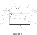
- Figure 3 shows a cross sectional side view of a main gases flow path 1 and a humidification chamber 13.
- the outlet aperture 7 and inlet aperture 8 allow for a pneumatic connection between the main gases flow 11, 12 and a gases space of the humidification chamber 13.
- the outlet aperture 7 and inlet aperture 8 act to provide a shunt (e.g. parallel) or secondary flow path to divert a portion of the gases flow 11, 12 in the main gases flow path from the main gases flow path through the humidification chamber 13 and back into the main gases flow path.
- a shunt e.g. parallel
- secondary flow path gas As the shunted or secondary flow path gas passes through the humidification chamber 13, it is humidified. Once the humidified gas rejoins the main gases flow path 1, it mixes with the main gases flow 11, 12.
- the mixture comprises the warmed and humidified gas from the shunt or secondary path and the gas from the main gases flow path 1.
- the pressure inside the main gases flow path 1 near the outlet aperture 7 is greater than the pressure inside the humidification source 13 and inside the main gases flow path 1 near the inlet aperture 8.
- the pressure in the humidification source 13 is greater than the pressure inside the main gases flow path 1 near the inlet aperture 8.
- This pressure gradient drives a flow of gas from the main gases flow path 1 into the humidification chamber 13 and then back into the main gases flow path 1.
- the higher pressure area inside the main gases flow path 1 near the outlet aperture 7 drives an outlet gases flow 10 from the main gases flow path 1 into the humidification chamber 13.
- the low pressure area inside the main gases flow path near the inlet aperture 8 drives an inlet gases flow 9 from the humidification chamber 13 into the main gases flow path 1.
- the flow rate of the shunted of secondary flow path gas (the inlet and outlet gases flows) is substantially smaller than that of the main gases flow. In some embodiments, the flow rate of the shunted or secondary flow path gas is between 0% and 40% of the main gases flow. In some embodiments, the flow rate of the shunted or secondary flow path gas is between 10% and 30% of the main gases flow. In some embodiments, the flow rate of the shunted or secondary flow path gas is 20% or 10% of the main gases flow.
- Figures 4 and 5 show top and side views, respectively, of an embodiment of a main gases flow path 101.
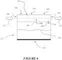
- Figure 6 shows the main gases flow path 101 as part of a humidification system.
- the main gases flow path 101 may be a venturi and may comprise an inlet portion 102, a neck portion 103, and an outlet portion 104. Gases flow into the gases inlet 106 along the gases flow path 111, 112 and out the gases outlet 105.
- the main gases flow path 101 also comprises an inlet aperture 108 and an outlet aperture 107.
- the outlet aperture 107 is located near the outlet portion 104 and optionally near the gases outlet 105.
- the inlet aperture 108 is located near the neck portion 103.
- the humidification system may comprise a main gases flow path 101 and the humidification source may comprise a humidification chamber 113.
- the humidification chamber may comprise a heater plate 115 configured to transfer energy to a liquid 114 (for example, water). Due to the pressure difference between the inlet aperture 108 and outlet aperture 107, an inlet gases flow 109 and an outlet gases flow 110 will be generated. Water vapour is added to the gases flow 110 as it passes though the humidification chamber. The further humidified gas then flows through the inlet aperture 110 and back into the main gases flow path 101.
- the inlet aperture 108 is located before the outlet aperture 107 in the main gases flow path 101.
- at least part of the gas in the main gases flow path 101 may be recirculated through the humidification chamber 113 multiple times.
- Figures 7 and 8 show side views of a main gases flow path 201 and figure 9 shows the main gases flow path 201 as part of a humidification system.
- the main gases flow path 201 comprises an inlet aperture 208 located near the neck portion 203, and is without an outlet aperture.
- the low pressure area near the inlet aperture 208 acts to generate a flow of gases 209 from the humidification chamber 213 into the main gases flow path 201.
- the humidification chamber 213 is not sealed to the external environment. This allows for gases to flow from the external environment into the humidification chamber 213 and replace the gas that has been transferred to the main gases flow 211, 212. Therefore no outlet aperture is necessary since flow enters the chamber from the atmosphere and not via the main gases flow path.
- the humidification source comprises an inlet, allowing a flow of gases to enter the humidification source, the inlet separate from the main gases flow path so that gases enter the humidification source before entering the main gases flow path via the inlet aperture 208.
- the humidification chamber comprises a valve configured to allow for a gas exchange between the external environment and the humidification chamber 213.
- the valve is a one way valve that only allows flow of gases into the humidification chamber 213.
- the pressure at a region of the gases flow path may be varied. In some embodiments, the pressure near at least the neck, inlet or outlet region(s) is varied. In some embodiments, the orientation of features in the flow path is changed. For example, the angle of a baffle or other feature to the direction of the flow of gases along the main flow path may be varied to create an area of low or high pressure. In some embodiments, the cross sectional area of the flow path can be varied. The cross sectional area may be varied by, for example, a valve or by compression or deformation of the flow path.
- At least part of the main gases flow path may be made of a malleable material such as a plastic, for example, a rubber or a polymer.
- Part of the main gases flow path may be deformed under an externally applied force (e.g. by a screw or other mechanism) such that a cross sectional area of the part of the main gases flow path may be varied.
- an externally applied force e.g. by a screw or other mechanism
- the inlet portion 2, 102, 202 is a first portion
- the neck portion 3, 103, 203 is a second portion.
- the first portion 2, 102, 103 comprises a larger cross sectional area than the second portion 3, 103, 203 so that with a flow of gases 11, 12, 111, 112, 211, 212 through the main gases flow path 1, 101, 201 a high pressure region is generated in the first portion 2, 102, 103 and a low pressure region is generated in the second portion 3, 103, 203.
- the inlet aperture 8, 108, 208 is located near to (e.g. close to or in) the second portion 3, 103, 203 so that the inlet aperture is near to or in the low pressure region.
- the low pressure region has a pressure less than a pressure of the humidification source, such that a pressure gradient is created between the humidification source and the low pressure region, causing a flow from the humidification source to the main gases flow path.
- the inlet aperture is illustrated as being near to and slightly downstream of the neck or second portion of the main gases flow path. Alternatively, the inlet aperture may be in or slightly upstream of the neck or second portion.
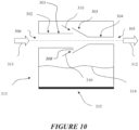
- Figure 10 shows an embodiment comprising a humidification chamber 313 and a main gases flow path 301.
- the main gases flow path 301 comprises features configured to generate a gases flow 310 from the humidification chamber 313 into the main gases flow 311, 312.
- the main gases flow path 301 comprises a gases inlet 306, a first portion 302, a second portion 304, a third portion 303, and a gases outlet 305. Gases flow into the gases inlet 306, pass through the first portion to the second portion via the third portion and out the gases outlet 305.
- the cross sectional area of the first portion 302 is greater than that of the second portion 304. Therefore, the velocity of the main gases flow 311, 312 is greater in the second portion 304 than it is in the first portion 302. This means the pressure in the second portion 304 is lower than the pressure in the first portion 302. This lower pressure region generates a gases flow 310 from the humidification chamber 313 into the main gases flow path 301.
- the gases flow 310 may contain water vapour provided to the gases flow 310 in the humidification chamber 313.
- the third portion 303 is of a funnel type shape and acts to transition the main gases flow 311, 312 from the first portion 302 to the second portion 303 and to provide a path for the gases flow 310 from the humidification chamber.
- the third portion 303 may be described as a transition portion, transitioning from the first portion 302 to the second portion 304, e.g. by tapering from a larger cross section to the smaller cross section of the second portion.
- An inlet aperture 308 may be provided at the transition portion, for the gases to pass from the chamber 313 to the main gases path 301.
- the inlet may be formed as an annular opening extending around the first portion 302 of the main gases flow path.
- the chamber may comprise an inlet (not shown in Figure 10 ), allowing a flow of gases to enter the humidification chamber, the inlet separate from the main gases flow path so that gases enter the humidification source before entering the main gases flow path via the inlet aperture 308.
- the third portion 303 may be integrally formed with at least one of the first 302 and second 304 portions and the gases flow 310 may be generated by an aperture located in either the second portion 304 or the third portion 303.
- the humidification chamber may be sealed and an aperture may be present in the first portion 302 to generate a flow of gases from the main gases flow path 301 into the humidification chamber 313.
- the inlet apertures of any of the humidification systems described above may comprise a valve, snorkel arrangement, membrane, filter, or the like configured to reduce the likelihood of water ingress into the gases flow path.
- the valve, membrane, or filter may be configured to reduce the likelihood of water ingress into the gases flow path but to allow gases therethrough.
- the snorkel arrangement may comprise a tortuous pathway that, in the case of where the humidification system is tilted or inverted, reduces the likelihood of flow into the gases flow path.
- Figure 11 shows an embodiment comprising a humidification chamber 413 and a main gases flow path 401.
- the main gases flow path 401 comprises features configured to generate a gases flow 409 from the humidification chamber 413 into the main gases flow 411, 412.
- the main gases flow path 401 comprises a gases inlet 406, a first portion 402, a second portion 404, and a gases outlet 405. Gases flow into the gases inlet 406 passes through the first and second portions 402, 404 and out the gases outlet 405.
- the cross sectional area of the first portion 402 is greater than that of the second portion 404.
- the gases flow path 411, 412 may comprise a transition portion 403.
- the transition portion 403 provides for a transition from the first portion 402 to the second portion 404.
- the inlet aperture 408 is located in the second portion 404 and the outlet aperture 407 is located in the first portion 402.
- the inlet aperture 408 generates a gases flow 409 from the humidification chamber 413 into the main gases flow path 401.
- the outlet aperture 408 generates a gases flow 410 from the main gases flow path 401 into the humidification chamber. It is envisaged that the positions of the first portion 402 and second portion 404 could be swapped.
- the main gases flow path 1, 101, 201, 301, 401 may be formed in a lid component of a humidification chamber, for example as depicted in Figures 3 , 6 and 9 .
- the lid component may seal the chamber 13, 113 but for the flow path through the chamber via the outlet aperture 107 and the inlet aperture 108.
- the lid component may provide an inlet (not shown) to the chamber separate from the main gases flow path, or the chamber may be provided with an inlet separate from the lid, e.g. via a side wall of the chamber.
- the main gases flow path 1, 101, 201, 301, 401 may be provided in a tubular component passing through a gases space of the chamber, for example as depicted in the arrangements of Figures 10 and 11 , or may be formed in a wall or base of the chamber.
- a connector part may comprise a main gases flow path for connecting a humidification source that is remote from the main gases flow path.
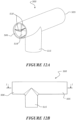
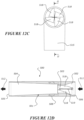
- Figures 12A to 12F illustrate a gases flow connector part 500 comprising a main gases flow path 501.
- the main gases flow path 501 comprises an inlet portion 502, a neck portion 503, and an outlet portion 504, as described in the earlier embodiments.
- the embodiment of Figures 12A to 12F is similar to the embodiment of Figures 7 to 9 , in that it has an inlet aperture 508 and is without an outlet aperture.
- an outlet aperture 7, 107, 407 may be provided, to allow a flow of gases from the main gases flow path to enter the humidification source, as described in the embodiments of Figures 1 to 3 , 4 to 6 and 11 .
- An outlet aperture may be positioned within the inlet portion 502, e.g. near to the inlet end 506 of the main gases flow path 501.
- the inlet portion 502 is a first portion and the neck portion 503 is a second portion.
- the first portion 502 comprises a larger cross sectional area than the second portion 503 so that with a flow of gases 511, 512 through the main gases flow path 501 a high pressure region is generated in the first portion 502 and a low pressure region is generated in the second portion 503.
Landscapes
- Health & Medical Sciences (AREA)
- Life Sciences & Earth Sciences (AREA)
- General Health & Medical Sciences (AREA)
- Engineering & Computer Science (AREA)
- Anesthesiology (AREA)
- Biomedical Technology (AREA)
- Heart & Thoracic Surgery (AREA)
- Hematology (AREA)
- Veterinary Medicine (AREA)
- Animal Behavior & Ethology (AREA)
- Public Health (AREA)
- Pulmonology (AREA)
- Emergency Medicine (AREA)
- Air Humidification (AREA)
- Fuel Cell (AREA)
- Wind Motors (AREA)
- Exhaust Gas After Treatment (AREA)
- Traffic Control Systems (AREA)
Applications Claiming Priority (4)
| Application Number | Priority Date | Filing Date | Title |
|---|---|---|---|
| US201562266123P | 2015-12-11 | 2015-12-11 | |
| PCT/IB2016/057285 WO2017098386A1 (en) | 2015-12-11 | 2016-12-02 | Humidification system |
| EP16872509.1A EP3386578B1 (de) | 2015-12-11 | 2016-12-02 | Befeuchtungssystem |
| EP22209231.4A EP4169561B1 (de) | 2015-12-11 | 2016-12-02 | Befeuchtungssystem |
Related Parent Applications (2)
| Application Number | Title | Priority Date | Filing Date |
|---|---|---|---|
| EP16872509.1A Division EP3386578B1 (de) | 2015-12-11 | 2016-12-02 | Befeuchtungssystem |
| EP22209231.4A Division EP4169561B1 (de) | 2015-12-11 | 2016-12-02 | Befeuchtungssystem |
Publications (2)
| Publication Number | Publication Date |
|---|---|
| EP4464359A2 true EP4464359A2 (de) | 2024-11-20 |
| EP4464359A3 EP4464359A3 (de) | 2025-02-26 |
Family
ID=59013776
Family Applications (3)
| Application Number | Title | Priority Date | Filing Date |
|---|---|---|---|
| EP22209231.4A Active EP4169561B1 (de) | 2015-12-11 | 2016-12-02 | Befeuchtungssystem |
| EP16872509.1A Active EP3386578B1 (de) | 2015-12-11 | 2016-12-02 | Befeuchtungssystem |
| EP24192000.8A Withdrawn EP4464359A3 (de) | 2015-12-11 | 2016-12-02 | Befeuchtungssystem |
Family Applications Before (2)
| Application Number | Title | Priority Date | Filing Date |
|---|---|---|---|
| EP22209231.4A Active EP4169561B1 (de) | 2015-12-11 | 2016-12-02 | Befeuchtungssystem |
| EP16872509.1A Active EP3386578B1 (de) | 2015-12-11 | 2016-12-02 | Befeuchtungssystem |
Country Status (5)
| Country | Link |
|---|---|
| US (4) | US11135395B2 (de) |
| EP (3) | EP4169561B1 (de) |
| AU (1) | AU2016367428B2 (de) |
| SG (2) | SG10202100138RA (de) |
| WO (1) | WO2017098386A1 (de) |
Families Citing this family (7)
| Publication number | Priority date | Publication date | Assignee | Title |
|---|---|---|---|---|
| US9649468B2 (en) | 2014-09-03 | 2017-05-16 | Fisher & Paykel Healthcare Limited | Respiratory gas humidifier |
| SG10202100138RA (en) | 2015-12-11 | 2021-02-25 | Fisher & Paykel Healthcare Ltd | Humidification system |
| US11306929B2 (en) * | 2018-09-09 | 2022-04-19 | Vornado Air, Llc | Portable steam humidifier |
| US11549699B2 (en) | 2017-10-03 | 2023-01-10 | Vornado Air, Llc | Portable humidifier |
| CN109806479B (zh) * | 2017-11-18 | 2022-08-16 | 宁波贝斯美德医用器械有限公司 | 具有内部隔墙的加湿室 |
| WO2023242808A1 (en) * | 2022-06-17 | 2023-12-21 | Fisher & Paykel Healthcare Limited | Medical tubes and connectors for breathing circuits |
| JP7846915B2 (ja) * | 2024-06-04 | 2026-04-16 | 伸和コントロールズ株式会社 | 加湿器、空気調和装置、及び流路部材 |
Family Cites Families (70)
| Publication number | Priority date | Publication date | Assignee | Title |
|---|---|---|---|---|
| US3123071A (en) * | 1964-03-03 | Anesthetic vapokizer | ||
| US1678625A (en) * | 1924-06-18 | 1928-07-24 | Wallace & Tiernan Inc | Apparatus for the therapeutic application of chlorine |
| GB826280A (en) | 1957-04-24 | 1959-12-31 | British Oxygen Co Ltd | Valve means for controlling the flow of inhalant gas to a patient |
| US3221737A (en) * | 1962-07-25 | 1965-12-07 | James A Felts | Device for vaporization of volatile anesthetic liquids |
| US3451409A (en) * | 1966-06-03 | 1969-06-24 | Gen Electric | Fluidic systems |
| FR2159732A5 (de) * | 1971-11-10 | 1973-06-22 | Mat Medical Sanitaire | |
| US3739767A (en) * | 1972-01-19 | 1973-06-19 | W Peters | Humidifier |
| US3842828A (en) | 1972-09-08 | 1974-10-22 | Bird F M | Pediatric ventilator |
| US4036919A (en) * | 1974-06-26 | 1977-07-19 | Inhalation Therapy Equipment, Inc. | Nebulizer-humidifier system |
| US3913843A (en) * | 1974-10-30 | 1975-10-21 | Respiratory Care | Humidifier |
| DE2522102C3 (de) | 1975-05-17 | 1978-05-03 | Draegerwerk Ag, 2400 Luebeck | Atemluftanfeuchter für Beatmungsvorrichtungen |
| US4014382A (en) * | 1975-05-21 | 1977-03-29 | Basil E. Demeur | Temperature and/or relative humidity control system |
| US4225542A (en) | 1978-12-12 | 1980-09-30 | Minnesota Mining And Manufacturing Company | Evaporative humidifier |
| US4417573A (en) | 1981-07-02 | 1983-11-29 | Bear Medical Systems, Inc. | Patient adaptor for medical ventilator |
| WO1983003876A1 (en) | 1982-05-03 | 1983-11-10 | Morris George Q | Liquid fuel carburetion system |
| US4634560A (en) * | 1984-02-29 | 1987-01-06 | Aluminum Company Of America | Aspirator pump and metering device |
| US4773448A (en) | 1987-02-26 | 1988-09-27 | Francis Norman L | Freeze-resistant plastic pipe and method for its manufacture |
| US5031612A (en) | 1990-04-24 | 1991-07-16 | Devilbiss Health Care, Inc. | System and method for delivering warm humidified air |
| US5373841A (en) * | 1992-02-04 | 1994-12-20 | Kyllonen; David M. | Self-operated nasal humidifier |
| US5373341A (en) | 1993-08-31 | 1994-12-13 | Eastman Kodak Company | Lockout override for cameras |
| EP0756502B1 (de) | 1994-04-19 | 1999-03-03 | Jakob Bösherz | Beatmungsgerät, insbesondere zur behandlung von ateminsuffizienzen, sowie verfahren zu dessen betrieb |
| US5632270A (en) | 1994-09-12 | 1997-05-27 | Puritan-Bennett Corporation | Method and apparatus for control of lung ventilator exhalation circuit |
| US5598837A (en) | 1995-06-06 | 1997-02-04 | Respironics, Inc. | Passive humidifier for positive airway pressure devices |
| JPH1028737A (ja) | 1996-07-16 | 1998-02-03 | Metoran:Kk | 加湿調整ユニット、人工呼吸器用加湿器及び加湿調整ユニットの製造方法 |
| JPH10137339A (ja) | 1996-11-07 | 1998-05-26 | Sumitomo Bakelite Co Ltd | 酸素濃縮装置における加湿装置 |
| AUPO425496A0 (en) | 1996-12-18 | 1997-01-16 | William A Cook Australia Pty Ltd | Medical humidifier |
| DE19808590C2 (de) | 1998-02-28 | 2003-03-20 | Draeger Medical Ag | Beatmungsanfeuchter |
| SE9801429D0 (sv) * | 1998-04-23 | 1998-04-23 | Siemens Elema Ab | Förgasare |
| EP1586345A1 (de) | 1999-12-10 | 2005-10-19 | Vapotherm, Inc. | Vorrichtung und Verfahren zur Atemwegstherapie |
| US6918389B2 (en) | 2000-03-21 | 2005-07-19 | Fisher & Paykel Healthcare Limited | Breathing assistance apparatus |
| US7559324B2 (en) | 2000-06-21 | 2009-07-14 | Fisher & Paykel Healthcare Limited | Conduit with heated wick |
| US6531206B2 (en) | 2001-02-07 | 2003-03-11 | 3M Innovative Properties Company | Microstructured surface film assembly for liquid acquisition and transport |
| JP2005527305A (ja) | 2002-05-29 | 2005-09-15 | アントニー,ジャン−ミッシェル | 医療用ガス調整装置 |
| AU2003245018A1 (en) * | 2002-07-22 | 2004-02-09 | Hasdi Matarasso | A respiratory aid apparatus and method |
| DE10234811C1 (de) * | 2002-07-31 | 2003-11-27 | Draeger Medical Ag | Atemgasanfeuchtersystem für einen Patienten |
| US7476212B2 (en) | 2003-06-12 | 2009-01-13 | Michael Spearman | Medical gas humidification system |
| ATE357966T1 (de) * | 2003-12-18 | 2007-04-15 | Bowles Fluidics Corp | Fluideinspritzer und mischvorrichtung |
| US20060070675A1 (en) * | 2004-10-06 | 2006-04-06 | Maxwell Hsu | Pressurized gas-water mixer |
| DE102005005349B3 (de) | 2005-02-05 | 2006-06-01 | Dräger Medical AG & Co. KG | Elektrisch beheizter Anästhesiemitteldosierer |
| DE102005054344B3 (de) | 2005-11-15 | 2007-06-28 | Dräger Medical AG & Co. KG | Flüssigkeitsverdampfer |
| AU2006320622B2 (en) * | 2005-12-01 | 2012-02-16 | Hydrate, Inc. | Inline vaporizer |
| US7509957B2 (en) | 2006-02-21 | 2009-03-31 | Viasys Manufacturing, Inc. | Hardware configuration for pressure driver |
| EP3782688B8 (de) | 2006-11-08 | 2022-11-02 | ResMed Pty Ltd | Beatmungsgerät |
| WO2008095245A1 (en) | 2007-02-09 | 2008-08-14 | Resmed Ltd | Humidification arrangement for a respiratory apparatus |
| US8550075B2 (en) * | 2007-06-28 | 2013-10-08 | Resmed Limited | Removable and/or replaceable humidifier |
| AU2008202098A1 (en) | 2007-07-17 | 2009-02-05 | Resmed Limited | A Humidifier and a Pressurised Water Supply |
| JP2010137339A (ja) | 2008-12-12 | 2010-06-24 | Olympus Corp | 生産装置及び生産システム |
| US9132250B2 (en) * | 2009-09-03 | 2015-09-15 | Breathe Technologies, Inc. | Methods, systems and devices for non-invasive ventilation including a non-sealing ventilation interface with an entrainment port and/or pressure feature |
| WO2010091259A2 (en) * | 2009-02-06 | 2010-08-12 | Vapotherm, Inc. | Heated nebulizer devices, nebulizer systems, and methods for inhalation therapy |
| AU2010206053B2 (en) | 2009-07-31 | 2014-08-07 | ResMed Pty Ltd | Wire Heated Tube with Temperature Control System, Tube Type Detection, and Active Over Temperature Protection for Humidifier for Respiratory Apparatus |
| CA2776552C (en) | 2009-10-09 | 2018-01-16 | Philip Morris Products S.A. | Aerosol generator including multi-component wick |
| EP4389182A3 (de) * | 2009-11-18 | 2024-07-31 | Fisher & Paykel Healthcare Limited | Nasenmaske |
| US10532177B2 (en) | 2009-12-22 | 2020-01-14 | Fisher & Paykel Healthcare Limited | Components for medical circuits |
| KR101814096B1 (ko) * | 2010-02-23 | 2018-01-02 | 아사히 유키자이 가부시키가이샤 | 인라인형 유체 혼합 장치 |
| CN103037928B (zh) | 2010-04-27 | 2016-10-12 | 费雪派克医疗保健有限公司 | 用于向患者供应气体的装置 |
| US9314582B2 (en) | 2010-11-23 | 2016-04-19 | Carefusion 2200, Inc. | Humidification system |
| RU2594241C2 (ru) | 2010-12-17 | 2016-08-10 | Конинклейке Филипс Электроникс Н.В. | Увлажнительная система для увлажнения газа, доставляемого пациенту |
| WO2012080941A1 (en) | 2010-12-17 | 2012-06-21 | Koninklijke Philips Electronics N.V. | System and method for administering humidified gas to a ventilated patient |
| WO2012100291A1 (en) | 2011-01-24 | 2012-08-02 | Resmed Limited | Humidifier |
| CN107335121B (zh) | 2011-06-16 | 2022-06-03 | 瑞思迈私人有限公司 | 加湿器和层式加热元件 |
| US9205220B2 (en) | 2011-09-30 | 2015-12-08 | Carefusion 207, Inc. | Fluted heater wire |
| JP6288861B2 (ja) * | 2012-05-22 | 2018-03-07 | コーニンクレッカ フィリップス エヌ ヴェKoninklijke Philips N.V. | 成形された気流による圧補助療法のためのシステム及び方法 |
| CN104519938B (zh) | 2012-07-03 | 2018-01-12 | 皇家飞利浦有限公司 | 紧凑型加湿器 |
| US9669172B2 (en) * | 2012-07-05 | 2017-06-06 | Resmed Limited | Discreet respiratory therapy system |
| DE102012223445A1 (de) | 2012-12-17 | 2014-06-18 | Linde Aktiengesellschaft | Medizinische Schlaucheinheit und Vorrichtung zur Verabreichung eines Atemgases |
| ITRM20130132A1 (it) * | 2013-03-06 | 2014-09-07 | Hsd Holding Smart Device S R L | Elemento inalatore di sostanze medicamentose. |
| WO2016028525A1 (en) * | 2014-08-18 | 2016-02-25 | Hancock Medical, Inc. | Portable pap device with humidification |
| US9649468B2 (en) | 2014-09-03 | 2017-05-16 | Fisher & Paykel Healthcare Limited | Respiratory gas humidifier |
| WO2016036260A1 (en) | 2014-09-03 | 2016-03-10 | Fisher & Paykel Healthcare Limited | Deterministically controlled humidification system |
| SG10202100138RA (en) | 2015-12-11 | 2021-02-25 | Fisher & Paykel Healthcare Ltd | Humidification system |
-
2016
- 2016-12-02 SG SG10202100138RA patent/SG10202100138RA/en unknown
- 2016-12-02 SG SG11201804570YA patent/SG11201804570YA/en unknown
- 2016-12-02 US US16/060,119 patent/US11135395B2/en active Active
- 2016-12-02 WO PCT/IB2016/057285 patent/WO2017098386A1/en not_active Ceased
- 2016-12-02 EP EP22209231.4A patent/EP4169561B1/de active Active
- 2016-12-02 EP EP16872509.1A patent/EP3386578B1/de active Active
- 2016-12-02 AU AU2016367428A patent/AU2016367428B2/en not_active Ceased
- 2016-12-02 EP EP24192000.8A patent/EP4464359A3/de not_active Withdrawn
-
2021
- 2021-08-27 US US17/446,277 patent/US11672941B2/en active Active
-
2023
- 2023-05-01 US US18/309,988 patent/US12357789B2/en active Active
-
2025
- 2025-06-25 US US19/249,735 patent/US20260021268A1/en active Pending
Also Published As
| Publication number | Publication date |
|---|---|
| SG11201804570YA (en) | 2018-06-28 |
| WO2017098386A1 (en) | 2017-06-15 |
| US20210386960A1 (en) | 2021-12-16 |
| US20180361106A1 (en) | 2018-12-20 |
| SG10202100138RA (en) | 2021-02-25 |
| EP4464359A3 (de) | 2025-02-26 |
| US12357789B2 (en) | 2025-07-15 |
| AU2016367428A1 (en) | 2018-06-21 |
| EP4169561A1 (de) | 2023-04-26 |
| AU2016367428B2 (en) | 2021-12-09 |
| US11135395B2 (en) | 2021-10-05 |
| US11672941B2 (en) | 2023-06-13 |
| EP3386578A4 (de) | 2019-07-17 |
| EP4169561B1 (de) | 2024-08-28 |
| US20230355914A1 (en) | 2023-11-09 |
| EP3386578A1 (de) | 2018-10-17 |
| US20260021268A1 (en) | 2026-01-22 |
| EP3386578B1 (de) | 2023-01-25 |
Similar Documents
| Publication | Publication Date | Title |
|---|---|---|
| US12357789B2 (en) | Humidification system | |
| US12397127B2 (en) | Respiratory humidification system | |
| US20230347095A1 (en) | Flow mixers for respiratory therapy systems | |
| US20210016031A1 (en) | Infant cpap device, interface and system | |
| US12156969B2 (en) | Respiratory gas humidifier | |
| EP3879148B1 (de) | Ventil mit innerem element | |
| EP3041558B1 (de) | Vorrichtung zur atemunterstützung | |
| US12569636B2 (en) | Nasal cannula with turbulation elements | |
| CN109715239B (zh) | 包括用于帮助呼吸的流体转向器的设备和方法 | |
| AU2020302871A1 (en) | Variable geometry cannula | |
| EP3846887B1 (de) | Unterdruckvorrichtungen und deren verwendungen |
Legal Events
| Date | Code | Title | Description |
|---|---|---|---|
| PUAI | Public reference made under article 153(3) epc to a published international application that has entered the european phase |
Free format text: ORIGINAL CODE: 0009012 |
|
| STAA | Information on the status of an ep patent application or granted ep patent |
Free format text: STATUS: THE APPLICATION HAS BEEN PUBLISHED |
|
| AC | Divisional application: reference to earlier application |
Ref document number: 3386578 Country of ref document: EP Kind code of ref document: P Ref document number: 4169561 Country of ref document: EP Kind code of ref document: P |
|
| AK | Designated contracting states |
Kind code of ref document: A2 Designated state(s): AL AT BE BG CH CY CZ DE DK EE ES FI FR GB GR HR HU IE IS IT LI LT LU LV MC MK MT NL NO PL PT RO RS SE SI SK SM TR |
|
| PUAL | Search report despatched |
Free format text: ORIGINAL CODE: 0009013 |
|
| AK | Designated contracting states |
Kind code of ref document: A3 Designated state(s): AL AT BE BG CH CY CZ DE DK EE ES FI FR GB GR HR HU IE IS IT LI LT LU LV MC MK MT NL NO PL PT RO RS SE SI SK SM TR |
|
| RIC1 | Information provided on ipc code assigned before grant |
Ipc: A61M 16/16 20060101AFI20250117BHEP Ipc: A61M 11/04 20060101ALI20250117BHEP |
|
| STAA | Information on the status of an ep patent application or granted ep patent |
Free format text: STATUS: THE APPLICATION IS DEEMED TO BE WITHDRAWN |
|
| 18D | Application deemed to be withdrawn |
Effective date: 20250701 |