EP3846887B1 - Unterdruckvorrichtungen und deren verwendungen - Google Patents
Unterdruckvorrichtungen und deren verwendungen Download PDFInfo
- Publication number
- EP3846887B1 EP3846887B1 EP19858179.5A EP19858179A EP3846887B1 EP 3846887 B1 EP3846887 B1 EP 3846887B1 EP 19858179 A EP19858179 A EP 19858179A EP 3846887 B1 EP3846887 B1 EP 3846887B1
- Authority
- EP
- European Patent Office
- Prior art keywords
- mixing chamber
- inlet
- valve
- air
- transport tube
- Prior art date
- Legal status (The legal status is an assumption and is not a legal conclusion. Google has not performed a legal analysis and makes no representation as to the accuracy of the status listed.)
- Active
Links
Images


Classifications
-
- A—HUMAN NECESSITIES
- A61—MEDICAL OR VETERINARY SCIENCE; HYGIENE
- A61M—DEVICES FOR INTRODUCING MEDIA INTO, OR ONTO, THE BODY; DEVICES FOR TRANSDUCING BODY MEDIA OR FOR TAKING MEDIA FROM THE BODY; DEVICES FOR PRODUCING OR ENDING SLEEP OR STUPOR
- A61M16/00—Devices for influencing the respiratory system of patients by gas treatment, e.g. ventilators; Tracheal tubes
- A61M16/021—Devices for influencing the respiratory system of patients by gas treatment, e.g. ventilators; Tracheal tubes operated by electrical means
- A61M16/022—Control means therefor
- A61M16/024—Control means therefor including calculation means, e.g. using a processor
-
- A—HUMAN NECESSITIES
- A61—MEDICAL OR VETERINARY SCIENCE; HYGIENE
- A61M—DEVICES FOR INTRODUCING MEDIA INTO, OR ONTO, THE BODY; DEVICES FOR TRANSDUCING BODY MEDIA OR FOR TAKING MEDIA FROM THE BODY; DEVICES FOR PRODUCING OR ENDING SLEEP OR STUPOR
- A61M16/00—Devices for influencing the respiratory system of patients by gas treatment, e.g. ventilators; Tracheal tubes
- A61M16/0003—Accessories therefor, e.g. sensors, vibrators, negative pressure
- A61M16/0009—Accessories therefor, e.g. sensors, vibrators, negative pressure with sub-atmospheric pressure, e.g. during expiration
- A61M16/0012—Accessories therefor, e.g. sensors, vibrators, negative pressure with sub-atmospheric pressure, e.g. during expiration by Venturi means
-
- A—HUMAN NECESSITIES
- A61—MEDICAL OR VETERINARY SCIENCE; HYGIENE
- A61B—DIAGNOSIS; SURGERY; IDENTIFICATION
- A61B5/00—Measuring for diagnostic purposes; Identification of persons
- A61B5/08—Measuring devices for evaluating the respiratory organs
- A61B5/087—Measuring breath flow
-
- A—HUMAN NECESSITIES
- A61—MEDICAL OR VETERINARY SCIENCE; HYGIENE
- A61M—DEVICES FOR INTRODUCING MEDIA INTO, OR ONTO, THE BODY; DEVICES FOR TRANSDUCING BODY MEDIA OR FOR TAKING MEDIA FROM THE BODY; DEVICES FOR PRODUCING OR ENDING SLEEP OR STUPOR
- A61M16/00—Devices for influencing the respiratory system of patients by gas treatment, e.g. ventilators; Tracheal tubes
- A61M16/0045—Means for re-breathing exhaled gases, e.g. for hyperventilation treatment
-
- A—HUMAN NECESSITIES
- A61—MEDICAL OR VETERINARY SCIENCE; HYGIENE
- A61M—DEVICES FOR INTRODUCING MEDIA INTO, OR ONTO, THE BODY; DEVICES FOR TRANSDUCING BODY MEDIA OR FOR TAKING MEDIA FROM THE BODY; DEVICES FOR PRODUCING OR ENDING SLEEP OR STUPOR
- A61M16/00—Devices for influencing the respiratory system of patients by gas treatment, e.g. ventilators; Tracheal tubes
- A61M16/10—Preparation of respiratory gases or vapours
- A61M16/1005—Preparation of respiratory gases or vapours with O2 features or with parameter measurement
-
- A—HUMAN NECESSITIES
- A61—MEDICAL OR VETERINARY SCIENCE; HYGIENE
- A61M—DEVICES FOR INTRODUCING MEDIA INTO, OR ONTO, THE BODY; DEVICES FOR TRANSDUCING BODY MEDIA OR FOR TAKING MEDIA FROM THE BODY; DEVICES FOR PRODUCING OR ENDING SLEEP OR STUPOR
- A61M16/00—Devices for influencing the respiratory system of patients by gas treatment, e.g. ventilators; Tracheal tubes
- A61M16/10—Preparation of respiratory gases or vapours
- A61M16/12—Preparation of respiratory gases or vapours by mixing different gases
- A61M16/122—Preparation of respiratory gases or vapours by mixing different gases with dilution
- A61M16/125—Diluting primary gas with ambient air
- A61M16/127—Diluting primary gas with ambient air by Venturi effect, i.e. entrainment mixers
-
- A—HUMAN NECESSITIES
- A61—MEDICAL OR VETERINARY SCIENCE; HYGIENE
- A61M—DEVICES FOR INTRODUCING MEDIA INTO, OR ONTO, THE BODY; DEVICES FOR TRANSDUCING BODY MEDIA OR FOR TAKING MEDIA FROM THE BODY; DEVICES FOR PRODUCING OR ENDING SLEEP OR STUPOR
- A61M16/00—Devices for influencing the respiratory system of patients by gas treatment, e.g. ventilators; Tracheal tubes
- A61M16/20—Valves specially adapted to medical respiratory devices
-
- G—PHYSICS
- G01—MEASURING; TESTING
- G01F—MEASURING VOLUME, VOLUME FLOW, MASS FLOW OR LIQUID LEVEL; METERING BY VOLUME
- G01F1/00—Measuring the volume flow or mass flow of fluid or fluent solid material wherein the fluid passes through a meter in a continuous flow
- G01F1/05—Measuring the volume flow or mass flow of fluid or fluent solid material wherein the fluid passes through a meter in a continuous flow by using mechanical effects
- G01F1/34—Measuring the volume flow or mass flow of fluid or fluent solid material wherein the fluid passes through a meter in a continuous flow by using mechanical effects by measuring pressure or differential pressure
- G01F1/36—Measuring the volume flow or mass flow of fluid or fluent solid material wherein the fluid passes through a meter in a continuous flow by using mechanical effects by measuring pressure or differential pressure the pressure or differential pressure being created by the use of flow constriction
- G01F1/40—Details of construction of the flow constriction devices
- G01F1/44—Venturi tubes
-
- G—PHYSICS
- G01—MEASURING; TESTING
- G01F—MEASURING VOLUME, VOLUME FLOW, MASS FLOW OR LIQUID LEVEL; METERING BY VOLUME
- G01F15/00—Details of, or accessories for, apparatus of groups G01F1/00 - G01F13/00 insofar as such details or appliances are not adapted to particular types of such apparatus
- G01F15/001—Means for regulating or setting the meter for a predetermined quantity
- G01F15/002—Means for regulating or setting the meter for a predetermined quantity for gases
-
- G—PHYSICS
- G01—MEASURING; TESTING
- G01F—MEASURING VOLUME, VOLUME FLOW, MASS FLOW OR LIQUID LEVEL; METERING BY VOLUME
- G01F15/00—Details of, or accessories for, apparatus of groups G01F1/00 - G01F13/00 insofar as such details or appliances are not adapted to particular types of such apparatus
- G01F15/001—Means for regulating or setting the meter for a predetermined quantity
- G01F15/003—Means for regulating or setting the meter for a predetermined quantity using electromagnetic, electric or electronic means
-
- G—PHYSICS
- G01—MEASURING; TESTING
- G01F—MEASURING VOLUME, VOLUME FLOW, MASS FLOW OR LIQUID LEVEL; METERING BY VOLUME
- G01F15/00—Details of, or accessories for, apparatus of groups G01F1/00 - G01F13/00 insofar as such details or appliances are not adapted to particular types of such apparatus
- G01F15/02—Compensating or correcting for variations in pressure, density or temperature
- G01F15/04—Compensating or correcting for variations in pressure, density or temperature of gases to be measured
- G01F15/043—Compensating or correcting for variations in pressure, density or temperature of gases to be measured using electrical means
- G01F15/046—Compensating or correcting for variations in pressure, density or temperature of gases to be measured using electrical means involving digital counting
-
- A—HUMAN NECESSITIES
- A61—MEDICAL OR VETERINARY SCIENCE; HYGIENE
- A61M—DEVICES FOR INTRODUCING MEDIA INTO, OR ONTO, THE BODY; DEVICES FOR TRANSDUCING BODY MEDIA OR FOR TAKING MEDIA FROM THE BODY; DEVICES FOR PRODUCING OR ENDING SLEEP OR STUPOR
- A61M16/00—Devices for influencing the respiratory system of patients by gas treatment, e.g. ventilators; Tracheal tubes
- A61M16/0057—Pumps therefor
- A61M16/0066—Blowers or centrifugal pumps
-
- A—HUMAN NECESSITIES
- A61—MEDICAL OR VETERINARY SCIENCE; HYGIENE
- A61M—DEVICES FOR INTRODUCING MEDIA INTO, OR ONTO, THE BODY; DEVICES FOR TRANSDUCING BODY MEDIA OR FOR TAKING MEDIA FROM THE BODY; DEVICES FOR PRODUCING OR ENDING SLEEP OR STUPOR
- A61M16/00—Devices for influencing the respiratory system of patients by gas treatment, e.g. ventilators; Tracheal tubes
- A61M16/06—Respiratory or anaesthetic masks
-
- A—HUMAN NECESSITIES
- A61—MEDICAL OR VETERINARY SCIENCE; HYGIENE
- A61M—DEVICES FOR INTRODUCING MEDIA INTO, OR ONTO, THE BODY; DEVICES FOR TRANSDUCING BODY MEDIA OR FOR TAKING MEDIA FROM THE BODY; DEVICES FOR PRODUCING OR ENDING SLEEP OR STUPOR
- A61M16/00—Devices for influencing the respiratory system of patients by gas treatment, e.g. ventilators; Tracheal tubes
- A61M16/20—Valves specially adapted to medical respiratory devices
- A61M16/201—Controlled valves
- A61M16/202—Controlled valves electrically actuated
-
- A—HUMAN NECESSITIES
- A61—MEDICAL OR VETERINARY SCIENCE; HYGIENE
- A61M—DEVICES FOR INTRODUCING MEDIA INTO, OR ONTO, THE BODY; DEVICES FOR TRANSDUCING BODY MEDIA OR FOR TAKING MEDIA FROM THE BODY; DEVICES FOR PRODUCING OR ENDING SLEEP OR STUPOR
- A61M16/00—Devices for influencing the respiratory system of patients by gas treatment, e.g. ventilators; Tracheal tubes
- A61M16/20—Valves specially adapted to medical respiratory devices
- A61M16/208—Non-controlled one-way valves, e.g. exhalation, check, pop-off non-rebreathing valves
-
- A—HUMAN NECESSITIES
- A61—MEDICAL OR VETERINARY SCIENCE; HYGIENE
- A61M—DEVICES FOR INTRODUCING MEDIA INTO, OR ONTO, THE BODY; DEVICES FOR TRANSDUCING BODY MEDIA OR FOR TAKING MEDIA FROM THE BODY; DEVICES FOR PRODUCING OR ENDING SLEEP OR STUPOR
- A61M16/00—Devices for influencing the respiratory system of patients by gas treatment, e.g. ventilators; Tracheal tubes
- A61M16/0003—Accessories therefor, e.g. sensors, vibrators, negative pressure
- A61M2016/0027—Accessories therefor, e.g. sensors, vibrators, negative pressure pressure meter
-
- A—HUMAN NECESSITIES
- A61—MEDICAL OR VETERINARY SCIENCE; HYGIENE
- A61M—DEVICES FOR INTRODUCING MEDIA INTO, OR ONTO, THE BODY; DEVICES FOR TRANSDUCING BODY MEDIA OR FOR TAKING MEDIA FROM THE BODY; DEVICES FOR PRODUCING OR ENDING SLEEP OR STUPOR
- A61M16/00—Devices for influencing the respiratory system of patients by gas treatment, e.g. ventilators; Tracheal tubes
- A61M16/0003—Accessories therefor, e.g. sensors, vibrators, negative pressure
- A61M2016/003—Accessories therefor, e.g. sensors, vibrators, negative pressure with a flowmeter
- A61M2016/0033—Accessories therefor, e.g. sensors, vibrators, negative pressure with a flowmeter electrical
-
- A—HUMAN NECESSITIES
- A61—MEDICAL OR VETERINARY SCIENCE; HYGIENE
- A61M—DEVICES FOR INTRODUCING MEDIA INTO, OR ONTO, THE BODY; DEVICES FOR TRANSDUCING BODY MEDIA OR FOR TAKING MEDIA FROM THE BODY; DEVICES FOR PRODUCING OR ENDING SLEEP OR STUPOR
- A61M16/00—Devices for influencing the respiratory system of patients by gas treatment, e.g. ventilators; Tracheal tubes
- A61M16/10—Preparation of respiratory gases or vapours
- A61M16/1005—Preparation of respiratory gases or vapours with O2 features or with parameter measurement
- A61M2016/102—Measuring a parameter of the content of the delivered gas
- A61M2016/1025—Measuring a parameter of the content of the delivered gas the O2 concentration
-
- A—HUMAN NECESSITIES
- A61—MEDICAL OR VETERINARY SCIENCE; HYGIENE
- A61M—DEVICES FOR INTRODUCING MEDIA INTO, OR ONTO, THE BODY; DEVICES FOR TRANSDUCING BODY MEDIA OR FOR TAKING MEDIA FROM THE BODY; DEVICES FOR PRODUCING OR ENDING SLEEP OR STUPOR
- A61M16/00—Devices for influencing the respiratory system of patients by gas treatment, e.g. ventilators; Tracheal tubes
- A61M16/10—Preparation of respiratory gases or vapours
- A61M16/1005—Preparation of respiratory gases or vapours with O2 features or with parameter measurement
- A61M2016/102—Measuring a parameter of the content of the delivered gas
- A61M2016/103—Measuring a parameter of the content of the delivered gas the CO2 concentration
-
- A—HUMAN NECESSITIES
- A61—MEDICAL OR VETERINARY SCIENCE; HYGIENE
- A61M—DEVICES FOR INTRODUCING MEDIA INTO, OR ONTO, THE BODY; DEVICES FOR TRANSDUCING BODY MEDIA OR FOR TAKING MEDIA FROM THE BODY; DEVICES FOR PRODUCING OR ENDING SLEEP OR STUPOR
- A61M2202/00—Special media to be introduced, removed or treated
- A61M2202/02—Gases
- A61M2202/0225—Carbon oxides, e.g. Carbon dioxide
-
- A—HUMAN NECESSITIES
- A61—MEDICAL OR VETERINARY SCIENCE; HYGIENE
- A61M—DEVICES FOR INTRODUCING MEDIA INTO, OR ONTO, THE BODY; DEVICES FOR TRANSDUCING BODY MEDIA OR FOR TAKING MEDIA FROM THE BODY; DEVICES FOR PRODUCING OR ENDING SLEEP OR STUPOR
- A61M2205/00—General characteristics of the apparatus
- A61M2205/10—General characteristics of the apparatus with powered movement mechanisms
-
- A—HUMAN NECESSITIES
- A61—MEDICAL OR VETERINARY SCIENCE; HYGIENE
- A61M—DEVICES FOR INTRODUCING MEDIA INTO, OR ONTO, THE BODY; DEVICES FOR TRANSDUCING BODY MEDIA OR FOR TAKING MEDIA FROM THE BODY; DEVICES FOR PRODUCING OR ENDING SLEEP OR STUPOR
- A61M2205/00—General characteristics of the apparatus
- A61M2205/33—Controlling, regulating or measuring
- A61M2205/3306—Optical measuring means
-
- A—HUMAN NECESSITIES
- A61—MEDICAL OR VETERINARY SCIENCE; HYGIENE
- A61M—DEVICES FOR INTRODUCING MEDIA INTO, OR ONTO, THE BODY; DEVICES FOR TRANSDUCING BODY MEDIA OR FOR TAKING MEDIA FROM THE BODY; DEVICES FOR PRODUCING OR ENDING SLEEP OR STUPOR
- A61M2205/00—General characteristics of the apparatus
- A61M2205/33—Controlling, regulating or measuring
- A61M2205/3317—Electromagnetic, inductive or dielectric measuring means
-
- A—HUMAN NECESSITIES
- A61—MEDICAL OR VETERINARY SCIENCE; HYGIENE
- A61M—DEVICES FOR INTRODUCING MEDIA INTO, OR ONTO, THE BODY; DEVICES FOR TRANSDUCING BODY MEDIA OR FOR TAKING MEDIA FROM THE BODY; DEVICES FOR PRODUCING OR ENDING SLEEP OR STUPOR
- A61M2205/00—General characteristics of the apparatus
- A61M2205/33—Controlling, regulating or measuring
- A61M2205/3331—Pressure; Flow
- A61M2205/3334—Measuring or controlling the flow rate
-
- A—HUMAN NECESSITIES
- A61—MEDICAL OR VETERINARY SCIENCE; HYGIENE
- A61M—DEVICES FOR INTRODUCING MEDIA INTO, OR ONTO, THE BODY; DEVICES FOR TRANSDUCING BODY MEDIA OR FOR TAKING MEDIA FROM THE BODY; DEVICES FOR PRODUCING OR ENDING SLEEP OR STUPOR
- A61M2205/00—General characteristics of the apparatus
- A61M2205/33—Controlling, regulating or measuring
- A61M2205/3368—Temperature
-
- A—HUMAN NECESSITIES
- A61—MEDICAL OR VETERINARY SCIENCE; HYGIENE
- A61M—DEVICES FOR INTRODUCING MEDIA INTO, OR ONTO, THE BODY; DEVICES FOR TRANSDUCING BODY MEDIA OR FOR TAKING MEDIA FROM THE BODY; DEVICES FOR PRODUCING OR ENDING SLEEP OR STUPOR
- A61M2205/00—General characteristics of the apparatus
- A61M2205/33—Controlling, regulating or measuring
- A61M2205/3375—Acoustical, e.g. ultrasonic, measuring means
-
- A—HUMAN NECESSITIES
- A61—MEDICAL OR VETERINARY SCIENCE; HYGIENE
- A61M—DEVICES FOR INTRODUCING MEDIA INTO, OR ONTO, THE BODY; DEVICES FOR TRANSDUCING BODY MEDIA OR FOR TAKING MEDIA FROM THE BODY; DEVICES FOR PRODUCING OR ENDING SLEEP OR STUPOR
- A61M2207/00—Methods of manufacture, assembly or production
-
- A—HUMAN NECESSITIES
- A61—MEDICAL OR VETERINARY SCIENCE; HYGIENE
- A61M—DEVICES FOR INTRODUCING MEDIA INTO, OR ONTO, THE BODY; DEVICES FOR TRANSDUCING BODY MEDIA OR FOR TAKING MEDIA FROM THE BODY; DEVICES FOR PRODUCING OR ENDING SLEEP OR STUPOR
- A61M2230/00—Measuring parameters of the user
- A61M2230/20—Blood composition characteristics
- A61M2230/205—Blood composition characteristics partial oxygen pressure (P-O2)
-
- A—HUMAN NECESSITIES
- A61—MEDICAL OR VETERINARY SCIENCE; HYGIENE
- A61M—DEVICES FOR INTRODUCING MEDIA INTO, OR ONTO, THE BODY; DEVICES FOR TRANSDUCING BODY MEDIA OR FOR TAKING MEDIA FROM THE BODY; DEVICES FOR PRODUCING OR ENDING SLEEP OR STUPOR
- A61M2230/00—Measuring parameters of the user
- A61M2230/60—Muscle strain, i.e. measured on the user
Definitions
- negative air pressure devices and uses thereof.
- negative air pressure devices that modulate CO 2 delivery for use in the treatment of sleep apnea and related conditions.
- CPAP Continuous Positive Airway Pressure
- OSA obstructive sleep apnea
- CPAP is underutilized.
- OSA obstructive sleep apnea
- CPAP is established as a highly efficacious treatment for OSA.
- its effectiveness has been limited by poor adherence. In fact, many patients with sleep apnea consider CPAP positive pressure to be extremely uncomfortable and drop out in less than 6 months.
- WO93/23102 A1 discloses a non-wasting respiratory stimulator for providing a CO2 enriched fresh air mixture.
- the respirator comprises a breathing port, a vent port and a mixing chamber, and methods of treating hypocapnia of various etiology, comprising administering a mixture of exhaled CO2 and fresh air, utilizing the non-wasting respiratory stimulator.
- United States patent application US 2005/028811 A1 discloses multitask medical treatment respiratory apparatus having a mask defining a chamber wherein the mask has a first port, a second port and a venting valve.
- a reservoir bag having a first opening is in communication with the first port or there may be a venturi device in communication with a second opening of the reservoir bag.
- One or more gas sources are in communication with the venturi device.
- United States patent application US 3653379 A discloses a breathing apparatus in which gas is delivered to a patient under pressure intermittently. Air or oxygen delivered into a venturi tube includes an adjustable nozzle for changing pressure as required for a particular patient's demand.
- negative air pressure devices and uses thereof.
- negative air pressure devices that modulate CO 2 delivery for use in the treatment of sleep apnea and related conditions.
- an improved treatment for sleeping apnea that is much more comfortable and effective than existing devices such as CPAP.
- intermittent negative air pressure or continuous negative air pressure devices that utilize the Bernoulli principle and Venturi effect to deliver CO 2 enriched air to subjects in need of treatment for sleep apnea.
- the devices described herein do not require cleaning, are comfortable, and do not require electricity to operate.
- the current invention provides a negative air pressure device according to claim 1.
- the device further comprises a face mask in operable communication with the transport tube (e.g., a face mask comprising valves).
- the transport tube further comprises an adjustment component configured to move the transport tube in closer or further proximity to the mixing chamber (e.g., an infinity screw or a motor).
- the inlet further comprises a valve configured to control the cross-sectional area of the inlet and/or flow of gas into the inlet.
- a valve configured to control the cross-sectional area of the inlet and/or flow of gas into the inlet.
- the present disclosure is not limited to particular valves. Examples include, but are not limited to, a two-way valve (e.g., a butterfly valve) or a one-way valve (e.g., an umbrella valve).
- the device comprises two or more (e.g., 2 3, 4, 5, or more) inlets and/or outlets.
- the valve is configured to move with the axis of the inlet (e.g., via a screw motor).
- the outlet is covered by a filter.
- a secondary flow inlet causes the flow to enter tangentially with respect to the mixing chamber. In some embodiments, the secondary flow enters radially with respect to the main flow.
- the outlet/inlet comprises a valve. The present disclosure is not limited to a location of the inlet. In some embodiments, the inlet is located on the top of the mixing chamber, on the side of the transport tube, or another location. In some embodiments, the inlet comprises an actuator that controls movement of air through the actuator.
- the constriction generates negative pressure via the venturi effect.
- the device is enclosed in a case.
- the device further comprises an external source of gas (e.g., CO 2 or air) in operable communication with the device.
- the device provides intermittent, periodic, or continuous negative air pressure (e.g., via the venturi effect).
- the device traps CO 2 in the mixing chamber.
- the processor controls CO 2 levels by controlling flow of atmospheric air or enriched CO 2 air into the device through the inlet.
- inventions provide a method of treating sleep apnea in a subject, comprising: applying the device or system described herein to a subject in need thereof.
- the devices, systems, and methods described herein are suitable for use in treating any type of sleep apnea (e.g., including but not limited to, obstructive, central or mixed sleep apnea).
- negative air pressure devices and uses thereof.
- negative air pressure devices that modulate CO 2 delivery for use in the treatment of sleep apnea.
- the devices described herein are based, in part, on the Bernoulli principle, Venturi effect, and mass and energy transfer equations. Common realizations of these concepts in other systems are (a) ejectors, (b) injectors, (c) air jets, (d) eductors, (e) jet pumps, (f) carburetors, (g) cyclonic separators etc.
- the Bernoulli theorem teaches us that the energy of flowing fluid (for small height differences) remains constant, but this energy can take a form of either kinetic energy or potential energy (in the pure form of pressure for horizonal flow). In order words, if a fluid accelerates its pressure will drop and vice-versa, while the total energy remains unchanged.
- the changes in pressure and velocity can be made to occur by narrowing or widening the tube or sections of the tube.
- the cross-section area of the tube or of the constraint can have any shape, e.g. circular or rectangular.
- the same effect of changing pressure and kinetic energy can be created using nozzles. Because of the increase in the velocity, the pressure of the moving fluid becomes lower than of any surrounding fluids, which cause the latter to flow toward the area of lower pressure similarly the way air flows into vacuum.
- the Bernoulli principle and the Venturi effect show that regions where a fluid has a higher velocity cause a negative pressure.
- an increase in the speed of a fluid occurs simultaneously with a decrease in pressure or a decrease in the fluid's potential energy.
- these principals are used to create a region of low pressure that can be used to control the mixing between atmospheric air and either exhaled air and/or other gases such as CO 2 or O 2 . Because the devices described herein allow for control of the lower pressure, one can control both the intensity and the direction of the secondary gas and thus the mixing of the gas. Thus, contamination of the non-disposable parts is avoided.
- valves there is no need to use valves to control the amount of CO 2 inside the mixing chamber, however one can still use them if desired.
- the tube throat is constrained by an exterior actuator without putting it in direct contact with the exhaled air.
- a valve, diaphragm, needle of any other means is used to reduce the cross-section in the tube both/either at the exit/exits and/or in the inlets (primary or secondary). More or less cross-section area provides a more or less differential pressure and hence more or less mixing. Again, this avoids contamination since the air only travels from the outside (atmospheric) to the inside of the mixing chambers if there is a constraint in the tube.
- the devices described herein do not need to be rigid and can be constructed of any type of appropriate fiber or other material, e.g., paper, cardboard, plastic, metal or alloy (e.g., stainless steel), and ceramic. Because the devices can be constructed of an absorbing material, the device can control excess moisture (a common complain of CPAP users) and be disposable so cleaning is not needed (another common complain of CPAP users) and inexpensive to manufacture. Because the pressures involved are small (typically less than 20 mmHg), the mask and/or nasal pillows do not need to be very tight to avoid leaks, which are a source of complaint among users of PAP machines.
- the venturis are asymmetrical because in most of the applications a fluid can be adequately mixed in only one direction.
- they can be symmetrical, so the atmospheric air is mixed inside of the device in both the inhale and exhale phases in a similar fashion.
- Another advantage of the devices of the present disclosure is that they do not require a fan or blower to create the negative pressure but rather uses the kinetic energy of the inspired and/or expired air from the user to create the differential pressure. Thus, no third source of energy is necessary.
- a computer-controlled algorithm to control the amount of CO 2 based on one or more parameters (e.g., concentration of CO 2 in the device or mask, detection of apneic event, etc.).
- the apneic event can be detected by changes or lack of variation of flow, pressure, gas concentration, temperature, humidity, electrical resistivity, sound and/or electromagnetic changes inside or outside of the chamber and/or the mask.
- it can be detected by pulse oximetry, chest movement strain gage attached to the device or patient, chest movement image, and/or video.
- the devices described herein treat sleep apnea by delivering amounts of CO 2 either generated by patients during the exhale phase of the respiration or by an external gas reservoir or by concentrating the natural occurred CO 2 in the atmosphere.
- the amount of CO 2 delivered to the patient is controlled based on the measurements of the individuals' respiratory instability, e.g., hypoapnea or apnea events.
- VNAP Variable Negative Air Pressure device
- CNAP Constantly Negative Air Pressure
- the present devices are exemplified with controlling the amount of CO 2 delivered to the patients during the respiratory cycle in order to stabilize their respiration, the present disclosure is not limited to CO 2 regulation.
- the device is used to control the amount of any other gases exhaled by the patient such as, for example, O 2 , N 2 , etc. Exemplary devices are described herein.
- the VNAP or CNAP comprises at least one of(e.g., all three) modules: (1) a chamber comprise a venturi, air injector, air ejector or educator based on the Bernoulli principle to vary the mixing between the fresh/atmosperic air and CO 2 by using one or more actuators; (2) one or more sensors to detect apnea or hypoapnea; and (3) a control mechanism for delivering the required amount of CO 2 used to stabilize the patients' respiration.
- a chamber comprise a venturi, air injector, air ejector or educator based on the Bernoulli principle to vary the mixing between the fresh/atmosperic air and CO 2 by using one or more actuators
- one or more sensors to detect apnea or hypoapnea
- a control mechanism for delivering the required amount of CO 2 used to stabilize the patients' respiration.
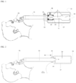
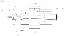
- Figure 1 shows a schematic drawing of one of the embodiments that used the air ejector principle.
- the amount of fresh air is controlled by the inserted tube position with respect to the primary mixing chamber.
- FIG. 1 shows mask 1, transport tube 2, transport tube adjustment component 3, mixing chamber 4, outlet/inlet 5, gas inlet 8, nozzle 10, actuator 6, and case 7.
- mask 1 can be any of the commonly used PAP masks or nose pillow or any other mask suitable to be used in exchanging gases from and to the subject. However, since the involved pressures are not as high as occurred in the PAP machines, it is not necessary to be as tightly attached to the users' face or nostrils as in the case of the PAP devices and thus it is more comfortable and more flexible.
- mask 1 comprises a plurality of valves as shown in FIG. 10 .
- the mask is obtained from commercial sources (e.g., from 3M corporation, St. Paul, MN, Honeywell, Morris Plains, NJ or other sources).
- the device comprises a transport tube adjustment component configured to move the nozzle in closer proximity to the mixing chamber. This allows for control of negative pressure and the corresponding flow rate.
- the present disclosure is not limited to particular adjustment components. Examples include, but are not limited to, an electric motor with or without gears or chains, an infinity screw (e.g., 370C-08700-N-CV, Transmotec, Boston, MA) or a piezoelectric motor (e.g., Piezo LEGS ® Linear 6N, PiezoMotor, Uppsala, Sweden), pneumatic actuator (e.g., MA-250 X 0.25-DA-RS, Universal Power Conversion, Savage, MN), or any other material that can contract, expand, shift or rotate due to stimulus such as voltage, electrical current, and temperature (e.g., artificial muscle).
- the present disclosure is not limited to particular materials for transport tube 2.
- the tube can be made of any biocompatible material or medical grade material, rigid or flexible.
- a gas inlet 8 is shown.
- the gas inlet provides the atmospheric air or any other gas or combination of gases from a third source such as, for example, CO 2 , O 2 , N 2 , etc.
- the inlet does not need to have a valve.
- a valve is added (not shown in FIG. 1 ) to control its cross-section area and hence the flow rate.
- the present disclosure is not limited to particular valves.
- the valve is a two-way valve, such as, for example, a butterfly valve or one-way valve such as, for example, an umbrella valve that allows only the flow to inside the device, or a combination of valves either passive or active such as solenoid or motorized valves that can control the flow rate in one or both directions.
- the inlet is connected to a pump to provide additional gases (not shown in FIG. 1).
- FIG. 1 shows a single inlet 8.
- two or more (e.g., 2, 3, 4, 5, or more) inlets 8 are utilized.
- several inlets are connected (e.g., at low pressure regions) along the surface of the device or in parallel or in series or in combination.
- the inlet or inlets 8 are tangential to the device, improving the mixing of gases.
- the inlet or inlets 8 are tangential to the device, improving the mixing of gases as shown in FIG. 14 .
- inlet 8 is not limited to a particular location of inlet 8.
- the inlet is shown on the top of mixing chamber 4.
- the inlet 8 may be located in any suitable location of mixing chamber 4.
- primary, secondary, and tertiary chambers are not limited to particular designs of the mixing chamber 4.
- the primary mixing chamber is proximal to the transport tube
- the secondary mixing chamber is proximal to the primary mixing chamber and distal to the tertiary mixing chamber.
- the primary mixing chamber 9 is located next to and in operable communication with the transport tube.
- the secondary mixing chamber 11 server as a diffuser or conduit to the tertiary mixing chamber 12 that further mixes the gases and stores the gases to be inhaled by the patient in the next respiratory cycle.
- the secondary mixing chamber 11 increases the static pressure to reduce the velocity of the excess gases into the atmosphere.
- the tertiary mixing chamber 12 stores gases.
- the tertiary mixing chamber 12 has a volume of 200 to 2000 ml (e.g., 200, 500, 1000, 1500, or 2000 ml).
- the outlet/inlet 5 is where gases return to the atmosphere or enter the device from the atmosphere.
- the outlet/inlet 5 comprises a passive or active valve in order to increase the pressure inside the device. In some embodiments, when the valve is closed, all gas intake and outflow flow through port 8.
- device comprises a case 7 to hold the structure in place and to protect the internal structure.
- the case 7 is solid, malleable, closed or with apertures.
- the present disclosure is not limited to particular materials for the case 7. Examples include, but are not limited to, metal, alloys, polymers or wood.
- the device comprises a nozzle 10 located at the distal end of the transport tube 2.
- Nozzle 10 serves to accelerate the exhaled air to create a negative pressure in the chamber, allowing the atmospheric air or other gas or gases to enter the mixing chamber 4.
- the nozzle diameter can be fixed or variable to control the velocity of the exhaled air and hence the negative pressure and flow rate through transport tube 2.
- the nozzle 10 shown in FIG. 1 has a converging tip to accelerate the flow and hence increase the negative pressure.
- the present disclosure is not limited to a nozzle 10 with a converging tip.
- a nozzle 10 with a constant cross-section is used (e.g., a nozzle with a diameter that is smaller than the mixing chamber 4 diameter).
- a converging-diverging nozzle 10 is used.
- the nozzle 10 has a lower diameter than the mixing chamber 4 or primary mixing chamber 9. If the nozzle 10 is completely flush with the mixing chamber 4, less mixing occurs with the atmospheric air. If the nozzle 10 is moved away from the entrance to the mixing chamber 4, there is no mixing with gases stored in the mixing chamber 4. Between the two extreme positions, more or less mixing occurs.
- 2 or more (e.g., 2, 3, 4, 5 or more) nozzles are used.
- the inlet 8 is shown in FIG. 1 is radial, a tangential inlet is also suitable, which further improve the mixing of gases reducing the need of longer length to properly mix the gases as shown in FIG. 10 .
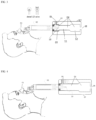
- FIGS 2-11 and 13-14 show additional designs and embodiments of the disclosed devices.
- FIG. 2 shown is a device where air enters the device on the side of transport tube 2 through the sides of the transport tube 2 where it enters the mixing chamber 4 as shown by the arrows.
- the amount of atmospheric air that is mixed is controlled by the relative position of the transport tube 2 and mixing chamber 4.
- mixing with atmospheric air occurs only at outlet/inlet 5.
- the amount of CO 2 in the mixing is maximum.
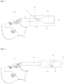
- FIG. 3 shown is a device that comprises a butterfly valve (or other valve) 13 in the gas inlet 8.
- the valve e.g., butterfly valve
- the valve is used in combination with the transport tube adjustment component 3 and/or other components described herein.
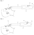
- FIG. 4 shown is a device where the flow of air through gas inlet 8 is controlled by constricting the gas inlet 8 with a screw (shown in FIG. 4 ) or other component that is able to constrict the gas inlet 8.
- nozzle 10 is generated by an actuator 14.
- the actuator 14 rotates counter clockwise it can completely shut the passage through gas inlet 8 so there is no mixing air will occur through outlet/inlet 5. Thus, maximum gas modulation treatment occurs.
- the actuator 14 moves clockwise, it becomes a nozzle 10 with variable cross-sectional area depending on the angle or the rotation.
- FIG. 6 shown is a device where the flow of air is controlled by constricting a region of mixing chamber 4.
- a point of constriction 15 is shown in the center (e.g., symmetrical venturi) of mixing chamber 4.
- the constriction can be placed in any suitable location.
- the constraint can be done in any way to change the cross-section area including, but not limited to, a butterfly valve, a diaphragm, guillotine valve, pinch valve etc.
- the negative pressure and hence the secondary flow is controlled by varying cross-section area of the constriction.
- FIGS. 7 and 8 shown are embodiments where the air control is based on constraint of the gas inlet 8.
- a physical constraint of the gas inlet 8 is used to control flow through the gas inlet 8.
- Other control component may be used (e.g., a screw as shown in FIG. 4 or a valve as shown in FIG. 8 ).
- the gas inlet 8 is placed in distal portion of a symmetrical venturi mixing chamber.
- the gas inlet 8 can be placed in any suitable location of the reduced cross-sectional area.
- FIG. 9 shown is a device comprising a blower component 16.
- the negative pressure and hence the mixing is controlled by an external blower, fan or pump.
- the negative pressure can be controlled not only by the options described in FIGS. 1-8 , but also by the velocity of the blower.
- the blower can blow the atmospheric air from left to right or from right to left. However, it is more advantageous if it is from left to right since the exhaled air does not get in contact with the blower, hence does not require a filter or constant cleaning of the blower.
- the present disclosure is not limited to a single blower. In some embodiments, 2 or more blowers are utilized in series or in parallel.
- the blower can be of any type including, but not limited to, positive displacement, helical screw, centrifugal, regenerative, syringe pump, diaphragm pump, piezoelectric or any other means for displacing air or gases.
- Commercially available blowers include, but are not limited to, those available from Master Flex (Cole-Parmer, Vernon Hills, IL).
- a secondary flow inlet 30 is provided.
- the secondary flow inlet 30 enters tangentially to the mixing chamber 31. In some embodiments, this improves the mixing of expired air and atmospheric air.
- FIG. 13 shown is a CAD design of an exemplary device.
- the inlet 17 guides the respiration flow into the device.
- the valve 19 (including components 18 and 20) moves right/left to allow more or less mixing with the atmospheric that enters the device.
- the valve 19 moves according to the movement of the screw motor 26 protected by the cap 27.
- the protection caps 24 and 25 protect the main body 21, 22 and 23 and the outlet is covered by a filter 28. All parts can be built in one piece but are divided in FIG. 13 to show an exemplary injection molding or 3D print plan.
- FIG. 14 shows in a physical realization of the CAD design of FIG. 13 plus the mask and hose.
- FIG. 15 shown are experimental results obtained using the device shown in FIG. 14 .
- Number 1 shows the concentration of CO 2 inside the mixing chamber when the valve is completely closed. Thus, the secondary flow is minimum.
- Number 2 shows the concentration of CO 2 when the valve is completely open. Hence, the secondary flow is maximum.
- Number 3 shows the variation of the concentration of CO 2 according the aperture of the valve, from maximum aperture to minimum aperture.
- a metabolic simulator with mass flow controller (Vacumed, CA) was used.
- a CO 2 (100% concentration) tank was connected to the simulator at a mass flow that creates a maximum concentration of 7000 ppm of CO 2 when the valve at the secondary flow is completely shut.
- the simulator was set to a tidal volume of 0.5 Liter/min and respiration rate of 15 respirations/minute, which are typical of a normal adult at rest state.
- the present disclosure is not limited to particular sizes of devices.
- the effective cross-section area of the device is larger than the cross-section area of a cylinder of 10 mm in diameter in order to avoid extra resistance to normal respiration.
- any specific cross-section area can be used given another path for the flow of gases to occur.
- the mixing chamber can have a diameter of 0 mm if the transport tube and inlet have effective diameters in combination of at least 15 mm. In this case, all the flow occurs from the inlet and transport tube with minimal addition of excess CO 2 or other gas/gases.
- systems comprising the devices described herein, a CO 2 sensor, and a processor and algorithm that controls CO 2 delivery by the device based on feedback from the CO 2 sensor and/or the patient.
- systems include a controller (e.g., controlled by the processor) that controls function of the device in order to modulate CO 2 levels and/or airflow through the device.
- CO 2 sensors are utilized (e.g., available from Kele, Memphis, TN or any number of other commercial suppliers).
- the CO 2 sensor is located in a suitable location or locations of the device in order measure the level of CO 2 in the mixing chamber (e.g., including but not limited to, internal to the mixing chamber or external with access via an inlet or valve).
- systems include components to detect apnea in a patient.
- the apneic event may be an apnea or a hypopnea, or the apneic event may be the absence of normal respiration (e.g., the temporary cessation of breathing) or a hypopnea (e.g., abnormally slow or shallow breathing).
- one or more sensors are provided in the airstream that measure the flow rate of each breath of the wearer and may sense the slowing or cessation of breathing or a reduction in airflow.
- the sensor may also be a pulse oximeter, a thermal sensor, an optical sensor, or the like, or combinations of the foregoing, as well as combinations of any of the sensors described herein.
- apneas may be detected, for example by pulse oximetry, or a thermal flow sensor (such as hot wire anemometer), or an optical sensor (such as that detects movement of a drag sensor), or a flow sensor (such as a pneumotachometer).
- a thermal flow sensor such as hot wire anemometer
- an optical sensor such as that detects movement of a drag sensor
- a flow sensor such as a pneumotachometer
- the controller controls the levels of CO 2 or the negative pressure in the device (e.g., by adjusting one or more valves, blowers, etc.) in order to treat the apnea.
- the sensor is configured to take readings at regular intervals (e.g., every microsecond, millisecond, second, minute, or longer intervals). The algorithm and processor then determine if apnea or hypoapnea is present and directs the controller to adjust the device accordingly.
- the controller further controls valves present in a mask as shown in FIG. 11 .
- the controller closes all the inlets/outlets of the valve, which decreases the differential pressure inside the mask during inspiration and increases the differential pressure during the respiration phase.
- two one-way valves as shown in FIG. 11
- a two-way valve both with preset open and close pressure will open, allowing the patient to breathe through the mask as shown in FIG. 11 .
- the present disclosure provides methods of treating apnea using the devices and systems described herein.
- the devices and systems are suitable for treatment of any type of apnea (e.g., obstructive, central or mixed sleep apnea).
- apnea e.g., obstructive, central or mixed sleep apnea
Landscapes
- Health & Medical Sciences (AREA)
- Pulmonology (AREA)
- Life Sciences & Earth Sciences (AREA)
- Veterinary Medicine (AREA)
- Biomedical Technology (AREA)
- Heart & Thoracic Surgery (AREA)
- Engineering & Computer Science (AREA)
- Animal Behavior & Ethology (AREA)
- General Health & Medical Sciences (AREA)
- Public Health (AREA)
- Anesthesiology (AREA)
- Hematology (AREA)
- Emergency Medicine (AREA)
- Physics & Mathematics (AREA)
- Fluid Mechanics (AREA)
- General Physics & Mathematics (AREA)
- Electromagnetism (AREA)
- Physiology (AREA)
- Biophysics (AREA)
- Pathology (AREA)
- Medical Informatics (AREA)
- Molecular Biology (AREA)
- Surgery (AREA)
- Respiratory Apparatuses And Protective Means (AREA)
Claims (15)
- Unterdruckatmungsvorrrichtung, umfassend eine Mischkammer (4, 31), die dazu ausgelegt ist, Luft über einen Venturi-Effekt zu bewegen, wobei die Atmungsvorrichtung umfasst: eine Transportröhre (2), die dazu ausgelegt ist, Luft zu transportieren, wobei die Transportröhre (2) ferner eine Düse (10) umfasst, die sich an einem distalen Ende der Transportröhre (2) in funktioneller Verbindung mit der Mischkammer (4, 31) befindet, wobei die Düse (10) dazu ausgelegt ist, Ausatemluft zu beschleunigen, um einen Unterdruck in der Kammer zu erzeugen, was erlaubt, dass atmosphärische Luft oder anderes Gas oder andere Gase in die Mischkammer gelangen; wobei die mindestens eine Mischkammer eine primäre (9), eine sekundäre (11) und eine tertiäre (12) Mischkammer umfasst, wobei die primäre Mischkammer (9) proximal zu der Transportröhre (2) ist, die sekundäre Mischkammer (11) proximal zu der primären Mischkammer (9) und distal zu der tertiären Mischkammer (12) ist, wobei die Mischkammer (4, 31) einen verengbaren Bereich (11) umfasst, wobei eine Verengung (15) dazu ausgelegt ist, über den Venturi-Effekt einen Unterdruck zu erzeugen; mindestens einen Gaseinlass (8, 30) in funktioneller Verbindung mit der Mischkammer (4, 31); und zusätzlich zu dem Gaseinlass (8, 30) mindestens einen Einlass/Auslass (5) in funktioneller Verbindung mit der Mischkammer (4, 31).
- Vorrichtung nach Anspruch 1, wobei die Vorrichtung ferner eine Gesichtsmaske (1) in funktioneller Verbindung mit der Transportröhre (2) umfasst, wobei vorzugsweise die Gesichtsmaske (1) ein oder mehrere Ventile umfasst.
- Vorrichtung nach einem der Ansprüche 1 bis 2, wobei die Transportröhre (2) ferner eine Verstellkomponente (3) umfasst, die dazu ausgelegt ist, die Transportröhre (2) in größere oder weitere Nähe zu der Mischkammer (4, 31) zu bewegen, wobei vorzugsweise die Verstellkomponente (3) eine Infinity-Schraube oder ein Motor ist.
- Vorrichtung nach einem der Ansprüche 1 bis 3, wobei:- der Einlass ferner ein Ventil umfasst, das dazu ausgelegt ist, die Querschnittsfläche des Einlasses zu steuern, wobei vorzugsweise das Ventil ein Zweiwegeventil, vorzugsweise ein Schmetterlingsventil, ist oder wobei das Ventil ein Einwegventil, vorzugsweise ein Schirmventil, ist; oder
wobei das Ventil dazu ausgelegt ist, sich entlang einer Achse des Einlasses zu bewegen, wobei vorzugsweise das Ventil von einem Schneckenmotor bewegt wird. - Vorrichtung nach einem der Ansprüche 1 bis 4, wobei sich der Einlass oben an der Mischkammer (4, 31) und/oder an der Seite der Transportröhre (2) befindet; und/oder wobei der Einlass eine Betätigungseinrichtung umfasst, die die Bewegung von Luft durch die Betätigungseinrichtung steuert.
- Vorrichtung nach einem der Ansprüche 1 bis 5, wobei die Vorrichtung zwei oder mehr Einlässe und/oder Auslässe umfasst, wobei vorzugsweise der Auslass von einem Filter (28) abgedeckt ist.
- Vorrichtung nach einem der Ansprüche 1 bis 6, wobei die Vorrichtung ferner einen sekundären Strömungseinlass umfasst, wobei vorzugsweise der sekundäre Strömungseinlass tangential zur Mischkammer (4, 31) in die Vorrichtung gelangt.
- Vorrichtung nach einem der Ansprüche 1 bis 7, wobei eine Verengung (15) über den Venturi-Effekt einen Unterdruck erzeugt, wobei vorzugsweise die Verengung (15) von einem Ventil oder einer Membran gesteuert wird.
- Vorrichtung nach einem der Ansprüche 1 bis 8, wobei die Vorrichtung ferner eine externe Gasquelle in funktioneller Verbindung mit der Vorrichtung umfasst.
- Vorrichtung nach einem der Ansprüche 1 bis 9, wobei die Vorrichtung intermittierenden, periodischen oder kontinuierlichen Luftunterdruck bereitstellt.
- Vorrichtung nach einem der Ansprüche 1 bis 10, wobei die Vorrichtung in der Mischkammer (4, 31) CO2 speichert.
- System, umfassend:a) die Vorrichtung nach einem der Ansprüche 1 bis 11;b) mindestens einen Sensor, der aus der Gruppe bestehend aus einem CO2-Sensor, einem Drucksensor, einem Temperatursensor und einem Luftstromsensor ausgewählt ist; undc) einen Prozessor, der dazu ausgelegt ist, einen Algorithmus zu verwenden, um den CO2-Gehalt oder den Luftstrom zu steuern, der von der Vorrichtung bereitgestellt wird;
wobei vorzugsweise das System ferner eine Steuerung umfasst, die dazu ausgelegt ist, die Vorrichtung zu steuern und den CO2-Gehalt oder den Luftstrom zu modulieren. - System nach Anspruch 12, wobei der Prozessor den CO2-Gehalt oder Luftstrom steuert, indem er die Strömung durch den Einlass in die Vorrichtung steuert.
- Vorrichtung nach einem der Ansprüche 1-11 oder System nach einem der Ansprüche 12 bis 13 zur Verwendung in der Behandlung von Schlafapnoe.
- Vorrichtung oder System nach Anspruch 14 zur Verwendung in der Behandlung von obstruktiver, zentraler oder gemischter Schlafapnoe.
Applications Claiming Priority (2)
| Application Number | Priority Date | Filing Date | Title |
|---|---|---|---|
| US201862727331P | 2018-09-05 | 2018-09-05 | |
| PCT/US2019/049704 WO2020051304A1 (en) | 2018-09-05 | 2019-09-05 | Negative air pressure devices and uses thereof |
Publications (3)
| Publication Number | Publication Date |
|---|---|
| EP3846887A1 EP3846887A1 (de) | 2021-07-14 |
| EP3846887A4 EP3846887A4 (de) | 2022-06-01 |
| EP3846887B1 true EP3846887B1 (de) | 2024-02-21 |
Family
ID=69722602
Family Applications (1)
| Application Number | Title | Priority Date | Filing Date |
|---|---|---|---|
| EP19858179.5A Active EP3846887B1 (de) | 2018-09-05 | 2019-09-05 | Unterdruckvorrichtungen und deren verwendungen |
Country Status (3)
| Country | Link |
|---|---|
| US (1) | US20210330908A1 (de) |
| EP (1) | EP3846887B1 (de) |
| WO (1) | WO2020051304A1 (de) |
Families Citing this family (1)
| Publication number | Priority date | Publication date | Assignee | Title |
|---|---|---|---|---|
| US20230372600A1 (en) * | 2022-05-18 | 2023-11-23 | John Plain | Anti-choking device |
Family Cites Families (19)
| Publication number | Priority date | Publication date | Assignee | Title |
|---|---|---|---|---|
| US3653379A (en) * | 1970-08-20 | 1972-04-04 | Joseph G Glenn | Adjustable pressure ippb ventilator |
| US4463755A (en) * | 1981-05-18 | 1984-08-07 | Terumo Corporation | Breathing circuit |
| US4951661A (en) * | 1988-06-08 | 1990-08-28 | Thayer Medical Corporation | Quick-connect adapter valve for connecting nebulizer and fluid ventilator hose |
| AU4112593A (en) * | 1992-05-12 | 1993-12-13 | Gilbert D. Saul | Non-wasting respiratory stimulator and high altitude breathing device |
| IL114154A0 (en) * | 1994-06-17 | 1995-10-31 | Trudell Medical Ltd | Nebulizing catheter system and methods of use and manufacture |
| EP1109588B1 (de) * | 1998-09-04 | 2005-04-27 | Caradyne (R & D) Limited | Kontrollsystem zur erzeugung eines kontinuierlichen positiven atemwegdrucks |
| US6402697B1 (en) * | 1999-01-21 | 2002-06-11 | Metasensors, Inc. | Non-invasive cardiac output and pulmonary function monitoring using respired gas analysis techniques and physiological modeling |
| US7094206B2 (en) * | 1999-04-23 | 2006-08-22 | The Trustees Of Tufts College | System for measuring respiratory function |
| US8181650B2 (en) * | 2003-05-15 | 2012-05-22 | Robert Fayette Andrew Nelson | Multitask medical treatment respiratory apparatus |
| US20060180149A1 (en) * | 2003-07-22 | 2006-08-17 | Hasdi Matarasso | A respiratory aid system and method |
| WO2009003488A2 (en) * | 2007-06-29 | 2009-01-08 | Mermaid Care A/S | A gas mixing device for an air-way management system |
| US8876838B2 (en) * | 2008-03-07 | 2014-11-04 | Kevin Winiarski | Anti-choking device |
| US20100116270A1 (en) * | 2008-11-10 | 2010-05-13 | Edwards Paul L | Medical Ventilator System and Method Using Oxygen Concentrators |
| EP2776107B1 (de) * | 2011-11-11 | 2022-06-22 | ResMed Pty Ltd | Leitungsanordnung zur behandlung der atemwege |
| WO2013112470A1 (en) * | 2012-01-23 | 2013-08-01 | Aeon Research And Tecnology, Llc | Modular pulmonary treatment system |
| FR2988005B1 (fr) * | 2012-03-16 | 2021-01-29 | Georges Boussignac | Dispositif et systeme de respiration artificielle pour la reanimation d'une personne en etat d'arret cardiaque |
| US9669172B2 (en) * | 2012-07-05 | 2017-06-06 | Resmed Limited | Discreet respiratory therapy system |
| EP3113822B1 (de) * | 2014-03-04 | 2019-04-10 | Koninklijke Philips N.V. | Mischgasangereichertes druckunterstützungssystem |
| CN207662681U (zh) * | 2017-12-01 | 2018-07-27 | 无锡市尚沃医疗电子股份有限公司 | 智能化呼气采样装置 |
-
2019
- 2019-09-05 EP EP19858179.5A patent/EP3846887B1/de active Active
- 2019-09-05 US US17/273,381 patent/US20210330908A1/en active Pending
- 2019-09-05 WO PCT/US2019/049704 patent/WO2020051304A1/en not_active Ceased
Also Published As
| Publication number | Publication date |
|---|---|
| US20210330908A1 (en) | 2021-10-28 |
| EP3846887A4 (de) | 2022-06-01 |
| BR112021004171A2 (pt) | 2021-05-25 |
| WO2020051304A1 (en) | 2020-03-12 |
| EP3846887A1 (de) | 2021-07-14 |
Similar Documents
| Publication | Publication Date | Title |
|---|---|---|
| JP7324910B2 (ja) | 圧力調整弁 | |
| US9415183B2 (en) | Ventilation mask with integrated piloted exhalation valve | |
| EP3259002B1 (de) | Benutzerschnittstelle zur atemgasversorgung eines atemwegs | |
| JP6153725B2 (ja) | 取込みポートおよび/または圧力フィーチャを備える非密封式換気インターフェイスを含む、換気補助システムおよび換気装置 | |
| US7191781B2 (en) | Nasal ventilation interface and system | |
| US11833310B2 (en) | High flow nasal therapy system | |
| US20070144517A1 (en) | Breathing device | |
| JP2019520925A (ja) | 患者の人工呼吸または呼吸補助の際の粉末エアロゾルの呼吸制御への適用 | |
| WO2014138125A1 (en) | Ventilation mask with integrated piloted exhalation valve | |
| EP3846887B1 (de) | Unterdruckvorrichtungen und deren verwendungen | |
| US20230355907A1 (en) | Nasal cannula interface | |
| CN222899927U (zh) | 鼻接口 | |
| BR112021004171B1 (pt) | Dispositivo respiratório de pressão de ar negativa e sistema que compreende o dito dispositivo | |
| JP7511021B2 (ja) | 呼吸補助のための装置およびシステム | |
| CN117355350A (zh) | 用于呼吸系统的通气口 | |
| EP4157413B1 (de) | Sauerstoff pep kanüle |
Legal Events
| Date | Code | Title | Description |
|---|---|---|---|
| STAA | Information on the status of an ep patent application or granted ep patent |
Free format text: STATUS: THE INTERNATIONAL PUBLICATION HAS BEEN MADE |
|
| PUAI | Public reference made under article 153(3) epc to a published international application that has entered the european phase |
Free format text: ORIGINAL CODE: 0009012 |
|
| STAA | Information on the status of an ep patent application or granted ep patent |
Free format text: STATUS: REQUEST FOR EXAMINATION WAS MADE |
|
| 17P | Request for examination filed |
Effective date: 20210323 |
|
| AK | Designated contracting states |
Kind code of ref document: A1 Designated state(s): AL AT BE BG CH CY CZ DE DK EE ES FI FR GB GR HR HU IE IS IT LI LT LU LV MC MK MT NL NO PL PT RO RS SE SI SK SM TR |
|
| DAV | Request for validation of the european patent (deleted) | ||
| DAX | Request for extension of the european patent (deleted) | ||
| A4 | Supplementary search report drawn up and despatched |
Effective date: 20220503 |
|
| RIC1 | Information provided on ipc code assigned before grant |
Ipc: A62B 7/00 20060101ALI20220426BHEP Ipc: G01F 1/44 20060101ALI20220426BHEP Ipc: A61M 16/00 20060101AFI20220426BHEP |
|
| GRAP | Despatch of communication of intention to grant a patent |
Free format text: ORIGINAL CODE: EPIDOSNIGR1 |
|
| STAA | Information on the status of an ep patent application or granted ep patent |
Free format text: STATUS: GRANT OF PATENT IS INTENDED |
|
| INTG | Intention to grant announced |
Effective date: 20231110 |
|
| GRAS | Grant fee paid |
Free format text: ORIGINAL CODE: EPIDOSNIGR3 |
|
| GRAA | (expected) grant |
Free format text: ORIGINAL CODE: 0009210 |
|
| STAA | Information on the status of an ep patent application or granted ep patent |
Free format text: STATUS: THE PATENT HAS BEEN GRANTED |
|
| AK | Designated contracting states |
Kind code of ref document: B1 Designated state(s): AL AT BE BG CH CY CZ DE DK EE ES FI FR GB GR HR HU IE IS IT LI LT LU LV MC MK MT NL NO PL PT RO RS SE SI SK SM TR |
|
| REG | Reference to a national code |
Ref country code: GB Ref legal event code: FG4D |
|
| REG | Reference to a national code |
Ref country code: CH Ref legal event code: EP |
|
| REG | Reference to a national code |
Ref country code: DE Ref legal event code: R096 Ref document number: 602019047071 Country of ref document: DE |
|
| REG | Reference to a national code |
Ref country code: IE Ref legal event code: FG4D |
|
| P01 | Opt-out of the competence of the unified patent court (upc) registered |
Effective date: 20240221 |
|
| REG | Reference to a national code |
Ref country code: LT Ref legal event code: MG9D |
|
| REG | Reference to a national code |
Ref country code: NL Ref legal event code: MP Effective date: 20240221 |
|
| PG25 | Lapsed in a contracting state [announced via postgrant information from national office to epo] |
Ref country code: IS Free format text: LAPSE BECAUSE OF FAILURE TO SUBMIT A TRANSLATION OF THE DESCRIPTION OR TO PAY THE FEE WITHIN THE PRESCRIBED TIME-LIMIT Effective date: 20240621 |
|
| PG25 | Lapsed in a contracting state [announced via postgrant information from national office to epo] |
Ref country code: LT Free format text: LAPSE BECAUSE OF FAILURE TO SUBMIT A TRANSLATION OF THE DESCRIPTION OR TO PAY THE FEE WITHIN THE PRESCRIBED TIME-LIMIT Effective date: 20240221 |
|
| PG25 | Lapsed in a contracting state [announced via postgrant information from national office to epo] |
Ref country code: GR Free format text: LAPSE BECAUSE OF FAILURE TO SUBMIT A TRANSLATION OF THE DESCRIPTION OR TO PAY THE FEE WITHIN THE PRESCRIBED TIME-LIMIT Effective date: 20240522 |
|
| REG | Reference to a national code |
Ref country code: AT Ref legal event code: MK05 Ref document number: 1658556 Country of ref document: AT Kind code of ref document: T Effective date: 20240221 |
|
| PG25 | Lapsed in a contracting state [announced via postgrant information from national office to epo] |
Ref country code: HR Free format text: LAPSE BECAUSE OF FAILURE TO SUBMIT A TRANSLATION OF THE DESCRIPTION OR TO PAY THE FEE WITHIN THE PRESCRIBED TIME-LIMIT Effective date: 20240221 Ref country code: RS Free format text: LAPSE BECAUSE OF FAILURE TO SUBMIT A TRANSLATION OF THE DESCRIPTION OR TO PAY THE FEE WITHIN THE PRESCRIBED TIME-LIMIT Effective date: 20240521 Ref country code: NL Free format text: LAPSE BECAUSE OF FAILURE TO SUBMIT A TRANSLATION OF THE DESCRIPTION OR TO PAY THE FEE WITHIN THE PRESCRIBED TIME-LIMIT Effective date: 20240221 |
|
| PG25 | Lapsed in a contracting state [announced via postgrant information from national office to epo] |
Ref country code: ES Free format text: LAPSE BECAUSE OF FAILURE TO SUBMIT A TRANSLATION OF THE DESCRIPTION OR TO PAY THE FEE WITHIN THE PRESCRIBED TIME-LIMIT Effective date: 20240221 |
|
| PG25 | Lapsed in a contracting state [announced via postgrant information from national office to epo] |
Ref country code: AT Free format text: LAPSE BECAUSE OF FAILURE TO SUBMIT A TRANSLATION OF THE DESCRIPTION OR TO PAY THE FEE WITHIN THE PRESCRIBED TIME-LIMIT Effective date: 20240221 |
|
| PG25 | Lapsed in a contracting state [announced via postgrant information from national office to epo] |
Ref country code: RS Free format text: LAPSE BECAUSE OF FAILURE TO SUBMIT A TRANSLATION OF THE DESCRIPTION OR TO PAY THE FEE WITHIN THE PRESCRIBED TIME-LIMIT Effective date: 20240521 Ref country code: NO Free format text: LAPSE BECAUSE OF FAILURE TO SUBMIT A TRANSLATION OF THE DESCRIPTION OR TO PAY THE FEE WITHIN THE PRESCRIBED TIME-LIMIT Effective date: 20240521 Ref country code: NL Free format text: LAPSE BECAUSE OF FAILURE TO SUBMIT A TRANSLATION OF THE DESCRIPTION OR TO PAY THE FEE WITHIN THE PRESCRIBED TIME-LIMIT Effective date: 20240221 Ref country code: LT Free format text: LAPSE BECAUSE OF FAILURE TO SUBMIT A TRANSLATION OF THE DESCRIPTION OR TO PAY THE FEE WITHIN THE PRESCRIBED TIME-LIMIT Effective date: 20240221 Ref country code: IS Free format text: LAPSE BECAUSE OF FAILURE TO SUBMIT A TRANSLATION OF THE DESCRIPTION OR TO PAY THE FEE WITHIN THE PRESCRIBED TIME-LIMIT Effective date: 20240621 Ref country code: HR Free format text: LAPSE BECAUSE OF FAILURE TO SUBMIT A TRANSLATION OF THE DESCRIPTION OR TO PAY THE FEE WITHIN THE PRESCRIBED TIME-LIMIT Effective date: 20240221 Ref country code: GR Free format text: LAPSE BECAUSE OF FAILURE TO SUBMIT A TRANSLATION OF THE DESCRIPTION OR TO PAY THE FEE WITHIN THE PRESCRIBED TIME-LIMIT Effective date: 20240522 Ref country code: FI Free format text: LAPSE BECAUSE OF FAILURE TO SUBMIT A TRANSLATION OF THE DESCRIPTION OR TO PAY THE FEE WITHIN THE PRESCRIBED TIME-LIMIT Effective date: 20240221 Ref country code: ES Free format text: LAPSE BECAUSE OF FAILURE TO SUBMIT A TRANSLATION OF THE DESCRIPTION OR TO PAY THE FEE WITHIN THE PRESCRIBED TIME-LIMIT Effective date: 20240221 Ref country code: BG Free format text: LAPSE BECAUSE OF FAILURE TO SUBMIT A TRANSLATION OF THE DESCRIPTION OR TO PAY THE FEE WITHIN THE PRESCRIBED TIME-LIMIT Effective date: 20240221 Ref country code: AT Free format text: LAPSE BECAUSE OF FAILURE TO SUBMIT A TRANSLATION OF THE DESCRIPTION OR TO PAY THE FEE WITHIN THE PRESCRIBED TIME-LIMIT Effective date: 20240221 |
|
| PG25 | Lapsed in a contracting state [announced via postgrant information from national office to epo] |
Ref country code: PT Free format text: LAPSE BECAUSE OF FAILURE TO SUBMIT A TRANSLATION OF THE DESCRIPTION OR TO PAY THE FEE WITHIN THE PRESCRIBED TIME-LIMIT Effective date: 20240621 Ref country code: PL Free format text: LAPSE BECAUSE OF FAILURE TO SUBMIT A TRANSLATION OF THE DESCRIPTION OR TO PAY THE FEE WITHIN THE PRESCRIBED TIME-LIMIT Effective date: 20240221 |
|
| PG25 | Lapsed in a contracting state [announced via postgrant information from national office to epo] |
Ref country code: SE Free format text: LAPSE BECAUSE OF FAILURE TO SUBMIT A TRANSLATION OF THE DESCRIPTION OR TO PAY THE FEE WITHIN THE PRESCRIBED TIME-LIMIT Effective date: 20240221 Ref country code: PT Free format text: LAPSE BECAUSE OF FAILURE TO SUBMIT A TRANSLATION OF THE DESCRIPTION OR TO PAY THE FEE WITHIN THE PRESCRIBED TIME-LIMIT Effective date: 20240621 Ref country code: PL Free format text: LAPSE BECAUSE OF FAILURE TO SUBMIT A TRANSLATION OF THE DESCRIPTION OR TO PAY THE FEE WITHIN THE PRESCRIBED TIME-LIMIT Effective date: 20240221 Ref country code: LV Free format text: LAPSE BECAUSE OF FAILURE TO SUBMIT A TRANSLATION OF THE DESCRIPTION OR TO PAY THE FEE WITHIN THE PRESCRIBED TIME-LIMIT Effective date: 20240221 |
|
| PG25 | Lapsed in a contracting state [announced via postgrant information from national office to epo] |
Ref country code: DK Free format text: LAPSE BECAUSE OF FAILURE TO SUBMIT A TRANSLATION OF THE DESCRIPTION OR TO PAY THE FEE WITHIN THE PRESCRIBED TIME-LIMIT Effective date: 20240221 |
|
| PG25 | Lapsed in a contracting state [announced via postgrant information from national office to epo] |
Ref country code: SM Free format text: LAPSE BECAUSE OF FAILURE TO SUBMIT A TRANSLATION OF THE DESCRIPTION OR TO PAY THE FEE WITHIN THE PRESCRIBED TIME-LIMIT Effective date: 20240221 |
|
| PG25 | Lapsed in a contracting state [announced via postgrant information from national office to epo] |
Ref country code: CZ Free format text: LAPSE BECAUSE OF FAILURE TO SUBMIT A TRANSLATION OF THE DESCRIPTION OR TO PAY THE FEE WITHIN THE PRESCRIBED TIME-LIMIT Effective date: 20240221 Ref country code: EE Free format text: LAPSE BECAUSE OF FAILURE TO SUBMIT A TRANSLATION OF THE DESCRIPTION OR TO PAY THE FEE WITHIN THE PRESCRIBED TIME-LIMIT Effective date: 20240221 |
|
| PG25 | Lapsed in a contracting state [announced via postgrant information from national office to epo] |
Ref country code: SK Free format text: LAPSE BECAUSE OF FAILURE TO SUBMIT A TRANSLATION OF THE DESCRIPTION OR TO PAY THE FEE WITHIN THE PRESCRIBED TIME-LIMIT Effective date: 20240221 |
|
| PG25 | Lapsed in a contracting state [announced via postgrant information from national office to epo] |
Ref country code: SM Free format text: LAPSE BECAUSE OF FAILURE TO SUBMIT A TRANSLATION OF THE DESCRIPTION OR TO PAY THE FEE WITHIN THE PRESCRIBED TIME-LIMIT Effective date: 20240221 Ref country code: SK Free format text: LAPSE BECAUSE OF FAILURE TO SUBMIT A TRANSLATION OF THE DESCRIPTION OR TO PAY THE FEE WITHIN THE PRESCRIBED TIME-LIMIT Effective date: 20240221 Ref country code: RO Free format text: LAPSE BECAUSE OF FAILURE TO SUBMIT A TRANSLATION OF THE DESCRIPTION OR TO PAY THE FEE WITHIN THE PRESCRIBED TIME-LIMIT Effective date: 20240221 Ref country code: EE Free format text: LAPSE BECAUSE OF FAILURE TO SUBMIT A TRANSLATION OF THE DESCRIPTION OR TO PAY THE FEE WITHIN THE PRESCRIBED TIME-LIMIT Effective date: 20240221 Ref country code: DK Free format text: LAPSE BECAUSE OF FAILURE TO SUBMIT A TRANSLATION OF THE DESCRIPTION OR TO PAY THE FEE WITHIN THE PRESCRIBED TIME-LIMIT Effective date: 20240221 Ref country code: CZ Free format text: LAPSE BECAUSE OF FAILURE TO SUBMIT A TRANSLATION OF THE DESCRIPTION OR TO PAY THE FEE WITHIN THE PRESCRIBED TIME-LIMIT Effective date: 20240221 |
|
| REG | Reference to a national code |
Ref country code: DE Ref legal event code: R097 Ref document number: 602019047071 Country of ref document: DE |
|
| PG25 | Lapsed in a contracting state [announced via postgrant information from national office to epo] |
Ref country code: IT Free format text: LAPSE BECAUSE OF FAILURE TO SUBMIT A TRANSLATION OF THE DESCRIPTION OR TO PAY THE FEE WITHIN THE PRESCRIBED TIME-LIMIT Effective date: 20240221 |
|
| PLBE | No opposition filed within time limit |
Free format text: ORIGINAL CODE: 0009261 |
|
| STAA | Information on the status of an ep patent application or granted ep patent |
Free format text: STATUS: NO OPPOSITION FILED WITHIN TIME LIMIT |
|
| PG25 | Lapsed in a contracting state [announced via postgrant information from national office to epo] |
Ref country code: IT Free format text: LAPSE BECAUSE OF FAILURE TO SUBMIT A TRANSLATION OF THE DESCRIPTION OR TO PAY THE FEE WITHIN THE PRESCRIBED TIME-LIMIT Effective date: 20240221 |
|
| 26N | No opposition filed |
Effective date: 20241122 |
|
| PG25 | Lapsed in a contracting state [announced via postgrant information from national office to epo] |
Ref country code: MC Free format text: LAPSE BECAUSE OF FAILURE TO SUBMIT A TRANSLATION OF THE DESCRIPTION OR TO PAY THE FEE WITHIN THE PRESCRIBED TIME-LIMIT Effective date: 20240221 Ref country code: SI Free format text: LAPSE BECAUSE OF FAILURE TO SUBMIT A TRANSLATION OF THE DESCRIPTION OR TO PAY THE FEE WITHIN THE PRESCRIBED TIME-LIMIT Effective date: 20240221 |
|
| REG | Reference to a national code |
Ref country code: CH Ref legal event code: PL |
|
| PG25 | Lapsed in a contracting state [announced via postgrant information from national office to epo] |
Ref country code: LU Free format text: LAPSE BECAUSE OF NON-PAYMENT OF DUE FEES Effective date: 20240905 |
|
| REG | Reference to a national code |
Ref country code: BE Ref legal event code: MM Effective date: 20240930 |
|
| PG25 | Lapsed in a contracting state [announced via postgrant information from national office to epo] |
Ref country code: BE Free format text: LAPSE BECAUSE OF NON-PAYMENT OF DUE FEES Effective date: 20240930 |
|
| PG25 | Lapsed in a contracting state [announced via postgrant information from national office to epo] |
Ref country code: CH Free format text: LAPSE BECAUSE OF NON-PAYMENT OF DUE FEES Effective date: 20240930 |
|
| PG25 | Lapsed in a contracting state [announced via postgrant information from national office to epo] |
Ref country code: IE Free format text: LAPSE BECAUSE OF NON-PAYMENT OF DUE FEES Effective date: 20240905 |
|
| PGFP | Annual fee paid to national office [announced via postgrant information from national office to epo] |
Ref country code: DE Payment date: 20250929 Year of fee payment: 7 |
|
| PGFP | Annual fee paid to national office [announced via postgrant information from national office to epo] |
Ref country code: GB Payment date: 20250929 Year of fee payment: 7 |
|
| PGFP | Annual fee paid to national office [announced via postgrant information from national office to epo] |
Ref country code: FR Payment date: 20250925 Year of fee payment: 7 |