EP4462604A1 - Einstecksatz und verbinder mit einem derartigen einstecksatz - Google Patents
Einstecksatz und verbinder mit einem derartigen einstecksatz Download PDFInfo
- Publication number
- EP4462604A1 EP4462604A1 EP24174984.5A EP24174984A EP4462604A1 EP 4462604 A1 EP4462604 A1 EP 4462604A1 EP 24174984 A EP24174984 A EP 24174984A EP 4462604 A1 EP4462604 A1 EP 4462604A1
- Authority
- EP
- European Patent Office
- Prior art keywords
- insert
- spring
- actuating element
- plug
- leg
- Prior art date
- Legal status (The legal status is an assumption and is not a legal conclusion. Google has not performed a legal analysis and makes no representation as to the accuracy of the status listed.)
- Pending
Links
Images


Classifications
-
- H—ELECTRICITY
- H01—ELECTRIC ELEMENTS
- H01R—ELECTRICALLY-CONDUCTIVE CONNECTIONS; STRUCTURAL ASSOCIATIONS OF A PLURALITY OF MUTUALLY-INSULATED ELECTRICAL CONNECTING ELEMENTS; COUPLING DEVICES; CURRENT COLLECTORS
- H01R4/00—Electrically-conductive connections between two or more conductive members in direct contact, i.e. touching one another; Means for effecting or maintaining such contact; Electrically-conductive connections having two or more spaced connecting locations for conductors and using contact members penetrating insulation
- H01R4/58—Electrically-conductive connections between two or more conductive members in direct contact, i.e. touching one another; Means for effecting or maintaining such contact; Electrically-conductive connections having two or more spaced connecting locations for conductors and using contact members penetrating insulation characterised by the form or material of the contacting members
- H01R4/64—Connections between or with conductive parts having primarily a non-electric function, e.g. frame, casing, rail
-
- H—ELECTRICITY
- H01—ELECTRIC ELEMENTS
- H01R—ELECTRICALLY-CONDUCTIVE CONNECTIONS; STRUCTURAL ASSOCIATIONS OF A PLURALITY OF MUTUALLY-INSULATED ELECTRICAL CONNECTING ELEMENTS; COUPLING DEVICES; CURRENT COLLECTORS
- H01R12/00—Structural associations of a plurality of mutually-insulated electrical connecting elements, specially adapted for printed circuits, e.g. printed circuit boards [PCB], flat or ribbon cables, or like generally planar structures, e.g. terminal strips, terminal blocks; Coupling devices specially adapted for printed circuits, flat or ribbon cables, or like generally planar structures; Terminals specially adapted for contact with, or insertion into, printed circuits, flat or ribbon cables, or like generally planar structures
- H01R12/50—Fixed connections
- H01R12/51—Fixed connections for rigid printed circuits or like structures
- H01R12/55—Fixed connections for rigid printed circuits or like structures characterised by the terminals
- H01R12/58—Fixed connections for rigid printed circuits or like structures characterised by the terminals terminals for insertion into holes
- H01R12/585—Terminals having a press fit or a compliant portion and a shank passing through a hole in the printed circuit board
-
- H—ELECTRICITY
- H01—ELECTRIC ELEMENTS
- H01R—ELECTRICALLY-CONDUCTIVE CONNECTIONS; STRUCTURAL ASSOCIATIONS OF A PLURALITY OF MUTUALLY-INSULATED ELECTRICAL CONNECTING ELEMENTS; COUPLING DEVICES; CURRENT COLLECTORS
- H01R13/00—Details of coupling devices of the kinds covered by groups H01R12/70 or H01R24/00 - H01R33/00
- H01R13/40—Securing contact members in or to a base or case; Insulating of contact members
- H01R13/42—Securing in a demountable manner
- H01R13/428—Securing in a demountable manner by resilient locking means on the contact members; by locking means on resilient contact members
-
- H—ELECTRICITY
- H01—ELECTRIC ELEMENTS
- H01R—ELECTRICALLY-CONDUCTIVE CONNECTIONS; STRUCTURAL ASSOCIATIONS OF A PLURALITY OF MUTUALLY-INSULATED ELECTRICAL CONNECTING ELEMENTS; COUPLING DEVICES; CURRENT COLLECTORS
- H01R13/00—Details of coupling devices of the kinds covered by groups H01R12/70 or H01R24/00 - H01R33/00
- H01R13/46—Bases; Cases
- H01R13/502—Bases; Cases composed of different pieces
- H01R13/504—Bases; Cases composed of different pieces different pieces being moulded, cemented, welded, e.g. ultrasonic, or swaged together
- H01R13/5045—Bases; Cases composed of different pieces different pieces being moulded, cemented, welded, e.g. ultrasonic, or swaged together different pieces being assembled by press-fit
-
- H—ELECTRICITY
- H01—ELECTRIC ELEMENTS
- H01R—ELECTRICALLY-CONDUCTIVE CONNECTIONS; STRUCTURAL ASSOCIATIONS OF A PLURALITY OF MUTUALLY-INSULATED ELECTRICAL CONNECTING ELEMENTS; COUPLING DEVICES; CURRENT COLLECTORS
- H01R4/00—Electrically-conductive connections between two or more conductive members in direct contact, i.e. touching one another; Means for effecting or maintaining such contact; Electrically-conductive connections having two or more spaced connecting locations for conductors and using contact members penetrating insulation
- H01R4/28—Clamped connections, spring connections
- H01R4/48—Clamped connections, spring connections utilising a spring, clip, or other resilient member
- H01R4/4809—Clamped connections, spring connections utilising a spring, clip, or other resilient member using a leaf spring to bias the conductor toward the busbar
- H01R4/48185—Clamped connections, spring connections utilising a spring, clip, or other resilient member using a leaf spring to bias the conductor toward the busbar adapted for axial insertion of a wire end
- H01R4/4819—Clamped connections, spring connections utilising a spring, clip, or other resilient member using a leaf spring to bias the conductor toward the busbar adapted for axial insertion of a wire end the spring shape allowing insertion of the conductor end when the spring is unbiased
- H01R4/4821—Single-blade spring
-
- H—ELECTRICITY
- H01—ELECTRIC ELEMENTS
- H01R—ELECTRICALLY-CONDUCTIVE CONNECTIONS; STRUCTURAL ASSOCIATIONS OF A PLURALITY OF MUTUALLY-INSULATED ELECTRICAL CONNECTING ELEMENTS; COUPLING DEVICES; CURRENT COLLECTORS
- H01R4/00—Electrically-conductive connections between two or more conductive members in direct contact, i.e. touching one another; Means for effecting or maintaining such contact; Electrically-conductive connections having two or more spaced connecting locations for conductors and using contact members penetrating insulation
- H01R4/28—Clamped connections, spring connections
- H01R4/48—Clamped connections, spring connections utilising a spring, clip, or other resilient member
- H01R4/4809—Clamped connections, spring connections utilising a spring, clip, or other resilient member using a leaf spring to bias the conductor toward the busbar
- H01R4/4828—Spring-activating arrangements mounted on or integrally formed with the spring housing
- H01R4/4833—Sliding arrangements, e.g. sliding button
-
- H—ELECTRICITY
- H01—ELECTRIC ELEMENTS
- H01R—ELECTRICALLY-CONDUCTIVE CONNECTIONS; STRUCTURAL ASSOCIATIONS OF A PLURALITY OF MUTUALLY-INSULATED ELECTRICAL CONNECTING ELEMENTS; COUPLING DEVICES; CURRENT COLLECTORS
- H01R11/00—Individual connecting elements providing two or more spaced connecting locations for conductive members which are, or may be, thereby interconnected, e.g. end pieces for wires or cables supported by the wire or cable and having means for facilitating electrical connection to some other wire, terminal, or conductive member, blocks of binding posts
- H01R11/03—Individual connecting elements providing two or more spaced connecting locations for conductive members which are, or may be, thereby interconnected, e.g. end pieces for wires or cables supported by the wire or cable and having means for facilitating electrical connection to some other wire, terminal, or conductive member, blocks of binding posts characterised by the relationship between the connecting locations
- H01R11/05—Individual connecting elements providing two or more spaced connecting locations for conductive members which are, or may be, thereby interconnected, e.g. end pieces for wires or cables supported by the wire or cable and having means for facilitating electrical connection to some other wire, terminal, or conductive member, blocks of binding posts characterised by the relationship between the connecting locations the connecting locations having different types of direct connections
-
- H—ELECTRICITY
- H01—ELECTRIC ELEMENTS
- H01R—ELECTRICALLY-CONDUCTIVE CONNECTIONS; STRUCTURAL ASSOCIATIONS OF A PLURALITY OF MUTUALLY-INSULATED ELECTRICAL CONNECTING ELEMENTS; COUPLING DEVICES; CURRENT COLLECTORS
- H01R13/00—Details of coupling devices of the kinds covered by groups H01R12/70 or H01R24/00 - H01R33/00
- H01R13/46—Bases; Cases
- H01R13/516—Means for holding or embracing insulating body, e.g. casing, hoods
- H01R13/518—Means for holding or embracing insulating body, e.g. casing, hoods for holding or embracing several coupling parts, e.g. frames
Definitions
- the present invention relates to a plug-in insert for a connector, in particular a plug-in connector, preferably according to the preamble of claim 1, and furthermore to a connector with such a plug-in insert, preferably according to the preamble of claim 13.
- EP 3 312 940 B1 a contact for a plug connection element is known.
- the contact comprises a protective earthing element on which a contact device is provided which has a housing with two sockets for inserting a protective conductor wire.
- a contact device When inserting a protective conductor wire, a clamping edge of a spring element is pushed sideways by a feed end of the protective conductor wire, the insulating layer of which has been removed. Therefore, such a contact is only suitable for inserting a rigid conductor wire and the protective earthing element has a complicated structure and is not easy to manufacture.
- the present invention is based on the object of providing a plug-in insert.
- This plug-in insert is intended in particular to overcome the disadvantages of the prior art.
- the plug-in insert has at least one plug-in protective earthing arrangement and at least one plug-in contact arrangement. This achieves a simple, fast, reliable and vibration-resistant connection to a protective conductor wire and a power conductor wire, which is suitable not only for the assembly of a hard conductor wire but also for the assembly of a soft conductor wire.
- the protective earthing arrangement is characterized by a simple structure and low manufacturing costs.
- the object is achieved by a plug-in insert for a connector, preferably an electrical connector, in particular with the features of claim 1.
- the plug-in insert comprises a main body, a plurality of plug-in contact arrangements, a holding plate and at least one plug-in protective earthing arrangement arranged on a side wall of the insert, wherein a protective conductor can be connected to the protective earthing arrangement.
- the plug-in insert is characterized in particular in that the protective earthing arrangement comprises a protective earthing plate with a housing section, a spring, in particular an inverted and/or V-shaped spring, and a preferably hollow actuating element.
- the spring is at least partially housed in the actuating element.
- the actuating element is in a holding position on the spring.
- the spring is in a rest position with respect to the housing section when the actuating element is not subjected to a compressive force.
- the spring can preferably simultaneously perform both a pivoting movement and a particularly vertical movement in the insertion direction. This allows secure electrical contact to be made.
- the spring preferably due to its elasticity, allows both a pivoting movement and a vertical movement can be carried out in the opposite direction to the insertion direction when the pressure force is released. This allows for easy release.
- the spring has a straight leg and an inclined leg.
- the actuating element is provided with a ramp section, in particular on one side.
- the ramp section preferably has an inner profile that is designed to interact with the outer profile of the inclined leg. The spring can thus interact with the actuating element in an optimal manner.
- the outer profile of the inclined leg comprises a first step and a second step.
- the ramp section rests in particular on the first step in order to hold the actuating element in the holding position when the actuating element is not subjected to a compressive force.
- a protruding part of the second step engages the side wall of the housing section in order to hold the spring in the rest position.
- a movement of the actuating element in the insertion direction causes the inclined leg to pivot in the direction of the straight leg. This preferably causes the inclined leg to move away from the side wall of the housing section so that the protective conductor can be inserted between the inclined leg and the housing section.
- the movement of the actuating element in the insertion direction further causes the straight leg to move vertically in the insertion direction until it is stopped by a groove in a side wall of the main body.
- the insertion of the protective conductor is thus preferably at least facilitated.
- the inclined leg of the spring pivots away from the straight leg when the pressure force is released, whereby the protruding part of the inclined leg preferably snaps onto the inserted protective conductor in order to lock the protective conductor between the inclined leg and the side wall of the housing section.
- the protective conductor is now in close contact with the side wall of the housing section in order to form a protective earthing connection
- the straight leg of the spring moves vertically against the direction of insertion until a nose attached to the outside of the straight leg is stopped by an undercut section on the other, opposite side wall of the housing section. This enables secure contact.
- the holding plate is provided on a narrow side with a receptacle for receiving the housing section, the spring and the actuating element of the plug-in protective earthing arrangement.
- the receptacle preferably has a socket for receiving a head of the actuating element and an insertion opening for inserting the protective conductor.
- a tool preferably exerts a pressure force on the actuating element through the socket or can exert this force.
- the main body is provided on the narrow side with a receptacle for receiving a contact element of the protective earthing plate.
- the receptacle has the groove for stopping the straight leg of the spring.
- the contact arrangement comprises a contact housing part, an inverted V-shaped spring, an actuating element and an electrical contact.
- the spring is in particular partially housed in the actuating element, wherein the spring preferably comprises a straight leg and an inclined leg.
- a movement of the straight leg in the insertion direction is preferably stopped by a first stop on the bottom of the contact housing part.
- a movement of the straight leg against the insertion direction is preferably stopped by a second stop on a side surface of the contact housing part. This enables reliable function.
- the object is achieved by a connector, preferably an electrical connector, preferably with the features of claim 13.
- the connector comprises in particular a plug-in insert and a housing.
- the plug-in set is preferably designed according to the above descriptions.
- a quick connection to a hard and/or soft conductor wire can be achieved using a common tool (e.g. a screwdriver). Due to the permanent elasticity of the spring, a stable contact, preferably contact, with a lead wire can be ensured for a long time, thus achieving excellent vibration resistance in particular.
- a common tool e.g. a screwdriver
- the self-locking ability of the spring leads to a significantly increased tensile force of the lead wire, which preferably ensures a high contact force between the lead wire and the housing section of the protective earthing plate.
- the protective earthing arrangement is characterized by a simple overall structure and good ease of manufacture, which reduces production costs.
- the connector which includes the plug-in protective earthing arrangement and the plug-in contact arrangement, can find application in various industries, particularly the power industry, rail transportation, process control and chemical industries.
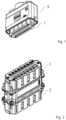
- Fig. 1 shows a three-dimensional representation of a connector, specifically a plug connector.
- the plug connector has a housing 9 in which plug-in inserts 1, 2 are accommodated.
- Fig. 2 shows the two plug-in inserts 1, 2, namely in particular a plug insert 1 and a socket insert 2, which are plugged together and accommodated in the housing 9.
- the individual inserts here each have a rectangular shape in particular.
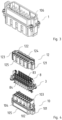
- Fig. 3 and 6 show a three-dimensional representation of insert 1 and insert 2 respectively, while Fig. 4 and 7 each show an exploded view of insert 1 or 2.
- the inserts 1, 2 each comprise a main body 10, 20 and a plurality of plug-in contact arrangements 8, 8', namely in particular plug-in plug contact arrangements 8 and plug-in socket contact arrangements 8'.
- the main body has a plurality of sockets 103, 203 for receiving an electrical contact 84, 84', namely in particular a plug contact 84 or a socket contact 84', of the contact arrangement 8, 8'.
- the inserts 1, 2 each further comprise a holding plate 12, 22, the upper side of which has a plurality of sockets 124, 224 each for receiving an actuating element 83 of the contact arrangement 8, 8'.
- the holding plate is locked to the main body by locking a locking window 125, 225 on a broad side, namely in particular the long side, of the holding plate with a locking element 104, 204 on a broad side of the main body, whereby the individual contact arrangement is fastened in the respective insert.
- Each main body is provided with a plug connection segment 105, 205 in order to establish a plug connection with the plug connection segment 205, 105 of the respective main body of the counter insert along an insertion direction S ( Fig. 5 and 8 ).
- the inserts 1, 2 are each provided with a plug-in protective earthing arrangement 3 on the side walls of the two narrow sides, namely in particular the transverse sides.
- the protective earthing arrangement 3 fixes the individual insert in the respective housing 9 via a screw and, on the other hand, provides a protective contact between the plug insert and the socket insert.
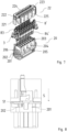
- Fig. 9 shows a three-dimensional representation of the protective earthing arrangement and Fig. 10 and 11 each show an exploded view of the protective earthing arrangement.
- the Protective earthing arrangement 3 comprises a protective earthing plate 4, an inverted V-shaped spring 5 and an actuating element 6.
- the protective earthing plate 4 comprises a contact element 42 which serves to provide an electrical contact with the protective earthing arrangement of the counter insert and extends along the insertion direction S, a housing portion 41 for receiving the spring and the actuating element and a flat plate portion 43 which has a screw hole for screw connection with a screw and runs perpendicular to the insertion direction S.
- the protective earthing plate 4 is made of metal, preferably of copper alloy.
- the inverted V-shaped spring 5 comprises a straight leg 51 and an inclined leg 52.
- the straight leg 51 is provided with a nose 511 on its outer side surface.
- the outer profile of the inclined leg 52 comprises a first step 521 and a second step 522.
- the second step is arranged further away from the straight leg 51 than the first step.
- the spring 5 is made of metal, preferably of stainless steel, particularly preferably of spring steel, most preferably of high-strength chromium-nickel spring steel.
- the actuating element 6 is hollow and has a head 63 on which a tool, for example a screwdriver, acts, two side walls 62 which extend downwards from the head, and a ramp section 61 ( Fig. 11 ) that extends between the two side walls.
- a tool for example a screwdriver
- two side walls 62 which extend downwards from the head
- a ramp section 61 ( Fig. 11 ) that extends between the two side walls.
- the two side walls and the ramp section together form an opening of the hollow actuator.
- the spring When assembled, the spring is partially accommodated in the actuating element.
- the straight leg 51 is introduced into the opening of the actuating element 6, guided by the two side walls 62, and at the same time the outer profile of the inclined leg 52 interacts in a form-fitting manner with the inner profile of the ramp section 61 until the underside of the ramp section 61 rests on the first step 521 of the inclined leg 52.
- the ramp section is stopped by the first step, so that the actuating element is in a holding position on the spring and the spring cannot penetrate further into the opening of the actuating element. Now the actuating element is not exposed to any pressure force, for example from a tool.
- the spring 5 and the actuating element 6 are accommodated as a combined component in the housing section 41 of the protective earthing plate 4.
- a protruding part 523 of the second step 522 of the inclined leg 52 of the spring 5 snaps onto a side plate of the housing section 41 and due to the rigidity and self-locking capability of the spring, the spring is in a rest position.
- Fig. 8 shows the resting position of the spring.
- a protective conductor 7 If a protective conductor 7 is to be inserted, the head of the actuating element is first pressed with a tool.
- a hard conductor wire, a multi-core hard conductor wire and also a soft conductor wire are conceivable as the protective conductor 7.
- the actuating element is now subjected to a compressive force along the insertion direction S. Under the action of the compressive force, the actuating element moves along the insertion direction and thus acts on the spring so that the spring executes a pivoting movement and a vertical movement at the same time.
- the inclined leg 52 is subjected to a compressive force of the actuating element so that it pivots towards the straight leg 51 and away from the side wall of the housing section 41 and at the same time the straight leg 51 moves vertically along the insertion direction (downward) under the action of the compressive force of the actuating element and protrudes from the housing section 41 via an opening (not shown) of the flat plate section 43 of the protective earthing plate 4.
- Show Fig. 5 and 8 a state in which the straight leg 51 protrudes from the flat plate portion 43 so that a gap is formed between the inclined leg and the side wall of the housing portion into which the protective conductor can be inserted.
- the side wall of the main body 10, 20 is provided with a groove 102, 202 to provide a lower stop of the straight leg 51.
- the tool is raised, whereby the pressure force is released. Since the actuating element no longer exerts any force on the spring, the inclined leg 52 pivots away from the straight leg 51 due to the elasticity, so that the protruding part 523 of the inclined leg 52 snaps onto the inserted protective conductor 7, whereby the protective conductor 7 is locked between the inclined leg 52 and the side wall of the housing section 41 and the Protective conductor is in close contact with the side wall to ensure a protective earthing connection.
- the straight leg 51 moves vertically against the insertion direction S (upwards) until the nose 511 of the straight leg 51 is stopped by an undercut section 411 on the side wall of the housing section 41.
- the side wall is in particular opposite the side wall of the housing section 41 which is in contact with the protective conductor 7. This means that the undercut section provides an upper stop of the straight leg 51. In other words, the straight leg can move vertically between the upper stop and the lower stop.
- the main body 10, 20 of the insert 1, 2 is provided on side walls of the two narrow sides with a receptacle 101, 201 for receiving the contact element 42 of the protective earthing arrangement 3.
- a groove 106 is formed on the side wall of the narrow side of the main body 10 of the plug insert 1, which serves to partially snap in the contact element 4 of the protective earthing arrangement 3.
- a guide groove 206 consisting of two ribs and serving to partially snap in the contact element 4 of the protective earthing arrangement 3 is formed on the side wall of the narrow side of the main body 20 of the socket insert 2.
- Fig. 5 and 8 clearly show the groove 102, 202 which is provided on the receptacle 101, 201 and serves as the lower stop of the straight leg 51.
- the holding plate 12, 22 of the insert 1, 2 is provided on side walls of the two narrow sides with a receptacle 121, 221 for receiving the actuating element 6 and the spring 5 of the protective earthing arrangement 3 as well as the housing section 41 of the protective earthing plate 4.
- the receptacle 121, 221 has a bushing 122, 222 for receiving the head 63 of the actuating element 6 and an insertion opening 123, 223 for inserting the protective conductor 7.
- the tool can exert a compressive force on the head 63 of the actuating element 6 through the bushing 122, 222 from above the holding plate 12, 22.
- the retaining plate seat rests against the upper surface of the flat plate portion of the protective earthing plate and the main body seat rests against the lower surface of the flat plate section of the protective earthing plate.
- a screw is screwed into the screw hole of the flat plate section.
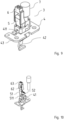
- the plug-in protective earthing arrangement 8, 8' is described below with reference to Fig. 12 to 15 described.
- Fig. 12 and 13 each show a three-dimensional representation or a bottom view of a plug insert arrangement 8.
- Fig. 14 and 15 each show a three-dimensional representation and a bottom view of a socket insert arrangement 8'.
- the plug insert arrangement 8 and the socket insert arrangement 8' differ from each other in their electrical contacts.
- the electrical contact of the plug insert arrangement 8 is a plug contact 84 and the electrical contact of the socket insert arrangement 8' is a socket contact 84'. Therefore, the description is only based on the example of the plug contact arrangement 8.
- the contact arrangement 8 has a contact housing part 81, an inverted V-shaped spring 82 and an actuating element 83.
- the spring 82 is at least partially accommodated in the actuating element 83. It preferably comprises a straight leg 821 and an inclined leg 822.
- the straight leg 821 does not protrude from the contact housing part 81 and instead a first stop 811, namely in particular a curved plate, is provided on the bottom of the contact housing part and a second stop 812 is provided on a side surface of the contact housing part.
Landscapes
- Details Of Connecting Devices For Male And Female Coupling (AREA)
- Coupling Device And Connection With Printed Circuit (AREA)
- Walking Sticks, Umbrellas, And Fans (AREA)
Abstract
Die vorliegende Erfindung betrifft einen Einsteckeinsatz für einen Verbinder. Er umfasst einen Hauptkörper, eine Vielzahl von Einsteckkontaktanordnungen, eine Halteplatte und mindestens eine Einsteck-Schutzerdungsanordnung, die an einer Seitenwand des Einsatzes angeordnet ist, wobei ein Schutzleiter mit der Schutzerdungsanordnung verbunden werden kann. Die vorliegende Erfindung betrifft ferner einen Verbinder, der den Einsteckeinsatz umfasst. Somit wird eine einfache, schnelle, zuverlässige und vibrationsfeste Verbindung mit einem Schutzleitungsdraht und einem Stromleitungsdraht erreicht, was sich nicht nur für die Montage eines harten Leitungsdrahts, sondern auch für die Montage eines weichen Leitungsdrahts eignet.
Description
- Die vorliegende Erfindung betrifft einen Einsteckeinsatz für einen Verbinder, insbesondere einen Steckverbinder, vorzugsweise nach dem Oberbegriff des Anspruchs 1, und ferner einen Verbinder mit einem derartigen Einsteckeinsatz, vorzugsweise nach dem Oberbegriff des Anspruchs 13.
- Als die heutzutage auf dem Markt gebräuchlichste Drahtverbindungsmethode wird eine Schraube zur Verbindung eines Drahts verwendet. Dies ist zeit- und kraftaufwendig und führt zu dem Problem gelöster Schrauben im Transport. Daher fand seit 2010 eine neuartige Push-in-Drahtverbindungstechnologie Anwendung auf das Gebiet elektrischer Verbindungen. Diese Technologie zeichnet sich durch erhöhte Einfachheit, höhere Effizienz, geringeren Zeit- und Kraftaufwand und verstärkte Vibrationsfestigkeit aus.
- Beispielsweise ist aus
EP 3 312 940 B1 ein Kontakt für ein Steckverbindungselement bekannt. Der Kontakt umfasst ein Schutzerdungselement, an dem eine Kontaktvorrichtung vorgesehen ist, die ein Gehäuse mit zwei Buchsen zum Einführen eines Schutzleitungsdrahts aufweist. Beim Einführen eines Schutzleitungsdrahts wird durch ein Einspeisungsende des Schutzleitungsdrahts, dessen Isolierschicht entfernt ist, eine Klemmkante eines Federelements seitwärts geschoben. Daher eignet sich ein derartiger Kontakt lediglich für das Einführen eines starren Leitungsdrahts und das Schutzerdungselement weist einen komplizierten Aufbau auf und ist nicht herstellungsfreundlich. - Daher liegt der vorliegenden Erfindung die Aufgabe zugrunde, einen Einsteckeinsatz bereitzustellen. Dieser Einsteckeinsatz soll insbesondere die Nachteile des Standes der Technik überwinden.
- Der Einsteckeinsatz weist wenigstens eine Einsteck-Schutzerdungsanordnung und wenigstens eine Einsteckkontaktanordnung auf. Somit wird eine einfache, schnelle, zuverlässige und vibrationsfeste Verbindung mit einem Schutzleitungsdraht und einem Stromleitungsdraht erreicht, was sich nicht nur für die Montage eines harten Leitungsdrahts, sondern auch für die Montage eines weichen Leitungsdrahts eignet. Die Schutzerdungsanordnung zeichnet sich durch einfachen Aufbau und niedrige Herstellungskosten aus.
- Gemäß einem bevorzugten Aspekt der vorliegenden Erfindung wird die Aufgabe gelöst durch einen Einsteckeinsatz für einen Verbinder, vorzugsweise einen elektrischen Verbinder, insbesondere mit den Merkmalen des Anspruchs 1.
- Der Einsteckeinsatz umfasst einen Hauptkörper, eine Vielzahl von Einsteckkontaktanordnungen, eine Halteplatte und mindestens eine Einsteck-Schutzerdungsanordnung, die an einer Seitenwand des Einsatzes angeordnet ist, wobei ein Schutzleiter mit der Schutzerdungsanordnung verbunden werden kann. Der Einsteckeinsatz zeichnet sich insbesondere dadurch aus, dass die Schutzerdungsanordnung eine Schutzerdungsplatte mit einem Gehäuseabschnitt, eine insbesondere umgekehrte und/oder V-förmige Feder und ein vorzugsweise hohles Betätigungselement umfasst. Die Feder ist zumindest teilweise in dem Betätigungselement untergebracht. Das Betätigungselement befindet sich in einer Halteposition auf der Feder. Die Feder befindet sich in einer Ruheposition in Bezug auf den Gehäuseabschnitt, wenn das Betätigungselement keiner Druckkraft ausgesetzt ist. Die Feder kann, wenn das Betätigungselement einer Druckkraft in einer Einsteckrichtung ausgesetzt ist, vorzugsweise gleichzeitig sowohl eine Schwenkbewegung als auch eine insbesondere vertikale Bewegung in der Einsteckrichtung ausführen. Damit kann eine sichere elektrische Kontaktierung erfolgen.
- In einer bevorzugten Ausführungsform ist vorgesehen, dass die Feder, vorzugsweise aufgrund ihrer Elastizität, sowohl eine Schwenkbewegung als auch eine vertikale Bewegung entgegen der Einsteckrichtung ausführen kann, wenn die Druckkraft gelöst wird. Damit kann ein einfaches Lösen erreicht werden.
- In einer besonderen Ausführungsform ist vorgesehen, dass die Feder einen geraden Schenkel und einen geneigten Schenkel aufweist. Das Betätigungselement ist insbesondere auf einer Seite mit einem Rampenabschnitt versehen. Der Rampenabschnitt weist vorzugsweise ein Innenprofil auf, das so konstruiert ist, dass es mit dem Außenprofil des geneigten Schenkels zusammenwirkt. Die Feder kann damit in optimaler Weise mit dem Betätigungselement zusammenwirken.
- In einer bevorzugten Ausführungsform ist vorgesehen, dass das Außenprofil des geneigten Schenkels eine erste Stufe und eine zweite Stufe umfasst. Der Rampenabschnitt ruht insbesondere auf der ersten Stufe, um das Betätigungselement in der Halteposition zu halten, wenn das Betätigungselement keiner Druckkraft ausgesetzt ist. Bevorzugt rastet ein vorstehender Teil der zweiten Stufe an der Seitenwand des Gehäuseabschnitts ein, um die Feder in der Ruheposition zu halten.
- In einer Ausführungsform ist insbesondere vorgesehen, dass, wenn das Betätigungselement einer Druckkraft in der Einsteckrichtung ausgesetzt ist, eine Bewegung des Betätigungselements in der Einsteckrichtung bewirkt, dass der geneigte Schenkel in Richtung des geraden Schenkels schwenkt. Dies bewirkt vorzugsweise, dass sich der geneigte Schenkel von der Seitenwand des Gehäuseabschnitts wegbewegt, so dass der Schutzleiter zwischen den geneigten Schenkel und den Gehäuseabschnitt eingeführt werden kann.
- Insbesondere bewirkt die Bewegung des Betätigungselements in der Einsteckrichtung ferner, dass sich der gerade Schenkel vertikal in der Einsteckrichtung bewegt, bis er durch eine Nut in einer Seitenwand des Hauptkörpers gestoppt wird. Das Einführen des Schutzleiters wird damit vorzugsweise zumindest erleichtert.
- In einer Ausführungsform ist bevorzugt vorgesehen, dass der geneigte Schenkel der Feder von dem geraden Schenkel wegschwenkt, wenn die Druckkraft gelöst wird, wodurch bevorzugt der vorstehende Teil des geneigten Schenkels auf den eingeführten Schutzleiter einschnappt, um den Schutzleiter zwischen dem geneigten Schenkel und der Seitenwand des Gehäuseabschnitts zu verriegeln. Bevorzugt steht nun der Schutzleiter in enger Berührung mit der Seitenwand des Gehäuseabschnitts, um eine Schutzerdungsverbindung herzustellen. Insbesondere bewegt sich der gerade Schenkel der Feder vertikal entgegen der Einsteckrichtung, bis eine an der Außenseite des geraden Schenkels angebrachte Nase durch einen hinterschnittenen Abschnitt an der anderen, gegenüberliegenden Seitenwand des Gehäuseabschnitts gestoppt wird. Damit wird eine sichere Kontaktierung ermöglicht.
- In einer bevorzugten Ausführungsform ist vorgesehen, dass die Halteplatte an einer Schmalseite mit einer Aufnahme zum Aufnehmen des Gehäuseabschnitts, der Feder und des Betätigungselements der Einsteck-Schutzerdungsanordnung versehen ist. Die Aufnahme weist vorzugsweise eine Buchse zum Aufnehmen eines Kopfes des Betätigungselements und eine Einstecköffnung zum Einführen des Schutzleiters auf. Ein Werkzeug übt bevorzugt eine Druckkraft auf das Betätigungselement durch die Buchse aus beziehungsweise kann diese ausüben.
- In einer bevorzugten Ausführungsform ist vorgesehen, dass der Hauptkörper an der Schmalseite mit einer Aufnahme zum Aufnehmen eines Kontaktelements der Schutzerdungsplatte versehen ist. Dabei weist insbesondere die Aufnahme die Nut zum Stoppen des geraden Schenkels der Feder auf.
- In einer Ausführungsform ist vorzugsweise vorgesehen, dass die Kontaktanordnung einen Kontaktgehäuseteil, eine umgekehrte V-förmige Feder, ein Betätigungselement und einen elektrischen Kontakt umfasst. Die Feder ist insbesondere teilweise in dem Betätigungselement untergebracht, wobei die Feder bevorzugt einen geraden Schenkel und einen geneigten Schenkel umfasst. Eine Bewegung des geraden Schenkels in der Einsteckrichtung wird bevorzugt durch einen ersten Anschlag am Boden des Kontaktgehäuseteils gestoppt. Eine Bewegung des geraden Schenkels entgegen der Einsteckrichtung wird bevorzugt durch einen zweiten Anschlag an einer Seitenfläche des Kontaktgehäuseteils gestoppt. Dies ermöglicht eine zuverlässige Funktion.
- Gemäß einem anderen Aspekt der vorliegenden Erfindung wird die Aufgabe gelöst durch einen Verbinder, vorzugsweise einen elektrischen Verbinder, , vorzugsweise mit den Merkmalen des Anspruchs 13. Der Verbinder umfasst insbesondere einen Einsteckeinsatz und ein Gehäuse. Der Einstecksatz ist vorzugsweise gemäß den obigen Beschreibungen ausgebildet.
- Mit der Gestaltung der vorliegenden Erfindung kann eine schnelle Verbindung mit einem harten und/oder weichen Leitungsdraht mithilfe eines üblichen Werkzeugs (beispielsweise eines Schraubendrehers) hergestellt werden. Aufgrund der dauerhaften Elastizität der Feder kann eine stabile Berührung, vorzugsweise Kontaktierung, mit einem Leitungsdraht für eine lange Zeit sichergestellt werden, womit insbesondere ausgezeichnete Vibrationsfestigkeit erreicht wird.
- Des Weiteren führt die Selbstverriegelbarkeit der Feder zu erheblich erhöhter Zugkraft des Leitungsdrahts, womit vorzugsweise eine hohe Berührungskraft zwischen dem Leitungsdraht und dem Gehäuseabschnitt der Schutzerdungsplatte sichergestellt wird. Darüber hinaus zeichnet sich die Schutzerdungsanordnung durch einfachen Gesamtaufbau und gute Herstellungsfreundlichkeit aus, womit die Produktionskosten gesenkt werden.
- Aufgrund der einfacheren und effizienteren Montage kann der Steckverbinder, der die Einsteck-Schutzerdungsanordnung und die Einsteckkontaktanordnung umfasst, Anwendung in verschiedenen Branchen, wie insbesondere der Stromindustrie, im Schienentransport, in der Prozesssteuerung und Chemieindustrie, finden.
- Bevorzugte Ausführungsbeispiele der vorliegenden Erfindung werden in den beiliegenden Zeichnungen dargestellt und nachfolgend näher erläutert. Darin zeigen:
- Fig. 1
- eine dreidimensionale Darstellung eines Verbinders;
- Fig. 2
- eine dreidimensionale Darstellung zusammengesteckter Einsätze;
- Fig. 3
- eine dreidimensionale Darstellung eines Steckereinsatzes;
- Fig. 4
- eine Explosionsansicht des Steckereinsatzes;
- Fig. 5
- eine Seitenansicht des Steckereinsatzes, wobei die Halteplatte entfernt ist;
- Fig. 6
- eine dreidimensionale Darstellung eines Buchseneinsatzes;
- Fig. 7
- eine Explosionsansicht des Buchseneinsatzes;
- Fig. 8
- eine Seitenansicht des Buchseneinsatzes, wobei die Halteplatte entfernt ist;
- Fig. 9
- eine dreidimensionale Darstellung einer Schutzerdungsanordnung;
- Fig. 10
- eine Explosionsansicht der Schutzerdungsanordnung;
- Fig. 11
- eine Explosionsansicht der Schutzerdungsanordnung aus einem anderen Blickwinkel;
- Fig. 12
- eine dreidimensionale Darstellung einer Steckereinsatzanordnung;
- Fig. 13
- eine Unteransicht der Steckereinsatzanordnung;
- Fig. 14
- eine dreidimensionale Darstellung einer Buchseneinsatzanordnung; und
- Fig. 15
- eine Unteransicht der Buchseneinsatzanordnung.
- Die beiliegenden Zeichnungen enthalten teilweise vereinfachte schematische Darstellungen. In einigen Fällen stehen gleiche Bezugszeichen für gleichartige, aber gegebenenfalls nicht identische Elemente. Unterschiedliche Ansichten gleicher Elemente können unterschiedlich skaliert werden.
-
Fig. 1 zeigt eine dreidimensionale Darstellung eines Verbinders, konkret eines Steckverbinders. Der Steckverbinder weist ein Gehäuse 9 auf, in dem Einsteckeinsätze 1, 2 aufgenommen sind. -
Fig. 2 zeigt die zwei Einsteckeinsätze 1, 2, nämlich insbesondere einen Steckereinsatz 1 und einen Buchseneinsatz 2, die zusammengesteckt und in dem Gehäuse 9 aufgenommen sind. Die einzelnen Einsätze weisen hier insbesondere jeweils eine rechteckige Form auf. - Nachfolgend wird der konkrete Aufbau der Einsätze 1, 2 unter Bezugnahme auf
Fig. 3 bis 8 beschrieben. -
Fig. 3 und6 zeigen jeweils eine dreidimensionale Darstellung des Einsatzes 1 bzw. des Einsatzes 2, währendFig. 4 und7 jeweils eine Explosionsansicht des Einsatzes 1 bzw. 2 zeigen. - Die Einsätze 1, 2 umfassen jeweils einen Hauptkörper 10, 20 und mehrere EinsteccKontaktanordnungen 8, 8', nämlich insbesondere Einsteck-Steckerkontaktanordnungen 8 und Einsteck-Buchsenkontaktanordnungen 8'. Der Hauptkörper weist mehrere Buchsen 103, 203 zum Aufnehmen eines elektrischen Kontakts 84, 84', nämlich insbesondere eines Steckerkontakts 84 beziehungsweise eines Buchsenkontakts 84', der Kontaktanordnung 8, 8' auf.
- Die Einsätze 1, 2 umfassen ferner jeweils eine Halteplatte 12, 22, deren Oberseite mehrere Buchsen 124, 224 jeweils zum Aufnehmen eines Betätigungselements 83 der Kontaktanordnung 8, 8' aufweist. Zur Montage wird eine Verriegelung der Halteplatte an dem Hauptkörper durch Verrasten eines Rastfensters 125, 225 an einer Breitseite, nämlich insbesondere der Längsseite, der Halteplatte mit einem Rastelement 104, 204 an einer Breitseite des Hauptkörpers erreicht, womit die einzelne Kontaktanordnung in dem jeweiligen Einsatz befestigt wird.
- Jeder Hauptkörper ist jeweils mit einem Steckverbindungssegment 105, 205 versehen, um eine Steckverbindung mit dem Steckverbindungssegment 205, 105 des jeweiligen Hauptkörpers des Gegeneinsatzes entlang einer Einsteckrichtung S (
Fig. 5 und8 ) herzustellen. - Wie sich aus
Fig. 4 und7 ergibt, sind die Einsätze 1, 2 an Seitenwänden der zwei Schmalseiten, nämlich insbesondere der Querseiten, ferner jeweils mit einer Einsteck-Schutzerdungsanordnung 3 versehen. Die Schutzerdungsanordnung 3 verwirklicht einerseits die Befestigung des einzelnen Einsatzes in dem jeweiligen Gehäuse 9 über eine Schraube und stellt andererseits einen Schutzkontakt zwischen dem Steckereinsatz und dem Buchseneinsatz bereit. - Nachfolgend wird der konkrete Aufbau der Einsteck-Schutzerdungsanordnung 3 unter Bezugnahme auf
Fig. 9 bis 11 beschrieben. -
Fig. 9 zeigt eine dreidimensionale Darstellung der Schutzerdungsanordnung undFig. 10 und11 zeigen jeweils eine Explosionsansicht der Schutzerdungsanordnung. Die Schutzerdungsanordnung 3 weist eine Schutzerdungsplatte 4, eine umgekehrte V-förmige Feder 5 und ein Betätigungselement 6 auf. - Die Schutzerdungsplatte 4 umfasst ein Kontaktelement 42, das zum Bereitstellen eines elektrischen Kontakts mit der Schutzerdungsanordnung des Gegeneinsatzes dient und sich entlang der Einsteckrichtung S erstreckt, einen Gehäuseabschnitt 41 zum Aufnehmen der Feder und des Betätigungselements und einen flachen Plattenabschnitt 43, der ein Schraubenloch zur Schraubverbindung mit einer Schraube aufweist und senkrecht zu der Einsteckrichtung S verläuft. Die Schutzerdungsplatte 4 ist aus Metall, vorzugsweise aus Kupferlegierung, hergestellt.
- Die umgekehrte V-förmige Feder 5 umfasst einen geraden Schenkel 51 und einen geneigten Schenkel 52. Der gerade Schenkel 51 ist an seiner Außenseitenfläche mit einer Nase 511 versehen. Das Außenprofil des geneigten Schenkels 52 umfasst eine erste Stufe 521 und eine zweite Stufe 522. Dabei ist die zweite Stufe weiter entfernt von dem geraden Schenkel 51 als die erste Stufe angeordnet. Die Feder 5 ist aus Metall, vorzugsweise aus Edelstahl, besonders bevorzugt aus Federstahl, am meisten bevorzugt aus hochfestem Chrom-Nickel-Federstahl, hergestellt.
- Das Betätigungselement 6 ist hohl ausgebildet und weist einen Kopf 63, auf den ein Werkzeug, beispielsweise ein Schraubendreher, wirkt, zwei Seitenwände 62, die sich ausgehend von dem Kopf nach unten erstrecken, und einen Rampenabschnitt 61 (
Fig. 11 ), der sich zwischen den zwei Seitenwänden erstreckt, auf. Die zwei Seitenwände und der Rampenabschnitt bilden gemeinsam eine Öffnung des hohlen Betätigungselements. - In montiertem Zustand ist die Feder teilweise in dem Betätigungselement aufgenommen. Im Detail wird der gerade Schenkel 51 unter Führung durch die zwei Seitenwände 62 in die Öffnung des Betätigungselements 6 eingeführt und gleichzeitig wirkt das Außenprofil des geneigten Schenkels 52 formschlüssig mit dem Innenprofil des Rampenabschnitts 61 zusammen, bis die Unterseite des Rampenabschnitts 61 auf der ersten Stufe 521 des geneigten Schenkels 52 ruht. Da mit anderen Worten die zweite Stufe aus der ersten Stufe herausragt und die Feder starr ausgebildet ist, wird der Rampenabschnitt durch die erste Stufe gestoppt, sodass sich das Betätigungselement in einer Halteposition an der Feder befindet und die Feder nicht weiter in die Öffnung des Betätigungselements eindringen kann. Nun ist das Betätigungselement keiner Druckkraft beispielsweise aus einem Werkzeug ausgesetzt.
- Gleichzeitig sind in montiertem Zustand die Feder 5 und das Betätigungselement 6 als ein kombiniertes Bauteil in dem Gehäuseabschnitt 41 der Schutzerdungsplatte 4 aufgenommen. Ein vorstehender Teil 523 der zweiten Stufe 522 des geneigten Schenkels 52 der Feder 5 schnappt auf einer Seitenplatte des Gehäuseabschnitts 41 ein und aufgrund der Starrheit und der Selbstverriegelbarkeit der Feder befindet sich die Feder in einer Ruheposition.
Fig. 8 zeigt die Ruheposition der Feder. - Wenn ein Schutzleiter 7 eingeführt werden soll, wird zunächst der Kopf des Betätigungselements mit einem Werkzeug gedrückt. Als Schutzleiter 7 sind ein harter Leitungsdraht, ein mehradriger harter Leitungsdraht und auch ein weicher Leitungsdraht denkbar. Nun ist das Betätigungselement einer Druckkraft entlang der Einsteckrichtung S ausgesetzt. Unter Einwirkung der Druckkraft bewegt sich das Betätigungselement entlang der Einsteckrichtung und wirkt somit auf die Feder, so dass die Feder gleichzeitig eine Schwenkbewegung und eine vertikale Bewegung ausführt.
- Im Detail ist der geneigte Schenkel 52 eine Druckkraft des Betätigungselements ausgesetzt, sodass er in Richtung des geraden Schenkels 51 und von der Seitenwand des Gehäuseabschnitts 41 weg schwenkt und gleichzeitig der gerade Schenkel 51 unter Einwirkung der Druckkraft des Betätigungselements sich entlang der Einsteckrichtung (nach unten) vertikal bewegt und über eine Öffnung (nicht dargestellt) des flachen Plattenabschnitts 43 der Schutzerdungsplatte 4 aus dem Gehäuseabschnitt 41 herausragt.
- Dabei zeigen
Fig. 5 und8 einen Zustand, in dem der gerade Schenkel 51 aus dem flachen Plattenabschnitt 43 herausragt, sodass zwischen dem geneigten Schenkel und der Seitenwand des Gehäuseabschnitts ein Zwischenraum gebildet wird, in den der Schutzleiter eingeführt werden kann. - Wie sich aus
Fig. 5 und8 ergibt, ist die Seitenwand des Hauptkörpers 10, 20 mit einer Nut 102, 202 versehen, um einen unteren Anschlag des geraden Schenkels 51 bereitzustellen. Nach Einführen des Schutzleiters 7 in den Zwischenraum wird das Werkzeug angehoben, womit die Druckkraft gelöst wird. Da nun das Betätigungselement keine Kraft mehr auf die Feder ausübt, schwenkt der geneigte Schenkel 52 aufgrund der Elastizität von dem geraden Schenkel 51 weg, sodass der vorstehende Teil 523 des geneigten Schenkels 52 auf den eingeführten Schutzleiter 7 einschnappt, womit der Schutzleiter 7 zwischen dem geneigten Schenkel 52 und der Seitenwand des Gehäuseabschnitts 41 verriegelt wird und der Schutzleiter in enger Berührung mit der Seitenwand steht, um eine Schutzerdungsverbindung sicherzustellen. Gleichzeitig bewegt sich der gerade Schenkel 51 vertikal entgegen der Einsteckrichtung S (nach oben), bis die Nase 511 des geraden Schenkels 51 durch einen hinterschnittenen Abschnitt 411 an der Seitenwand des Gehäuseabschnitts 41 gestoppt wird. Die Seitenwand liegt dabei insbesondere der mit dem Schutzleiter 7 in Berührung stehenden Seitenwand des Gehäuseabschnitts 41 gegenüber. Das heißt, der hinterschnittene Abschnitt stellt einen oberen Anschlag des geraden Schenkels 51 bereit. Mit anderen Worten kann sich der gerade Schenkel vertikal zwischen dem oberen Anschlag und dem unteren Anschlag bewegen. - Nun wird wieder auf
Fig. 3 bis 8 hingewiesen, um die Montage der Schutzerdungsanordnung 3 an dem Einsatz 1, 2 zu beschreiben. Der Hauptkörper 10, 20 des Einsatzes 1, 2 ist an Seitenwänden der zwei Schmalseiten mit einer Aufnahme 101, 201 zum Aufnehmen des Kontaktelements 42 der Schutzerdungsanordnung 3 versehen. - Wie in
Fig. 3 gezeigt, ist an der Seitenwand der Schmalseite des Hauptkörpers 10 des Steckereinsatzes 1 eine Nut 106, die dazu dient, das Kontaktelement 4 der Schutzerdungsanordnung 3 teilweise einzuschnappen, ausgebildet. - Wie in
Fig. 7 gezeigt, ist an der Seitenwand der Schmalseite des Hauptkörpers 20 des Buchseneinsatzes 2 eine Führungsnut 206, die aus zwei Rippen besteht und dazu dient, das Kontaktelement 4 der Schutzerdungsanordnung 3 teilweise einzuschnappen, ausgebildet. -
Fig. 5 und8 zeigen deutlich die Nut 102, 202, die an der Aufnahme 101, 201 vorgesehen ist und als unterer Anschlag des geraden Schenkels 51 dient. Die Halteplatte 12, 22 des Einsatzes 1, 2 ist an Seitenwänden der zwei Schmalseiten mit einer Aufnahme 121, 221 zum Aufnehmen des Betätigungselements 6 und der Feder 5 der Schutzerdungsanordnung 3 sowie des Gehäuseabschnitts 41 der Schutzerdungsplatte 4 versehen. Die Aufnahme 121, 221 weist eine Buchse 122, 222 zum Aufnehmen des Kopfes 63 des Betätigungselements 6 und eine Einstecköffnung 123, 223 zum Einführen des Schutzleiters 7 auf. Das Werkzeug kann eine Druckkraft auf den Kopf 63 des Betätigungselements 6 durch die Buchse 122, 222 von oberhalb der Halteplatte 12, 22 ausüben. - Wie sich aus
Fig. 3 und6 ergibt, liegt in montiertem Zustand die Aufnahme der Halteplatte gegen die obere Oberfläche des flachen Plattenabschnitts der Schutzerdungsplatte an und die Aufnahme des Hauptkörpers liegt gegen die untere Oberfläche des flachen Plattenabschnitts der Schutzerdungsplatte an. In das Schraubenloch des flachen Plattenabschnitts wird eine Schraube eingeschraubt. - Nachfolgend wird die Einsteck-Schutzerdungsanordnung 8, 8' unter Bezugnahme auf
Fig. 12 bis 15 beschrieben.Fig. 12 und 13 zeigen jeweils eine dreidimensionale Darstellung beziehungsweise eine Unteransicht einer Steckereinsatzanordnung 8.Fig. 14 und 15 zeigen jeweils eine dreidimensionale Darstellung beziehungsweise eine Unteransicht einer Buchseneinsatzanordnung 8'. Die Steckereinsatzanordnung 8 und die Buchseneinsatzanordnung 8' unterscheiden sich voneinander durch ihre elektrischen Kontakte. - Dabei ist der elektrische Kontakt der Steckereinsatzanordnung 8 ein Steckerkontakt 84 und der elektrische Kontakt der Buchseneinsatzanordnung 8' ein Buchsenkontakt 84'. Daher erfolgt die Beschreibung nur am Beispiel der Steckerkontaktanordnung 8. Die Kontaktanordnung 8 weist einen Kontaktgehäuseteil 81, eine umgekehrte V-förmige Feder 82 und ein Betätigungselement 83 auf. Die Feder 82 ist zumindest teilweise in dem Betätigungselement 83 aufgenommen. Sie umfasst vorzugsweise einen geraden Schenkel 821 und einen geneigten Schenkel 822.
- Aufgrund der Ähnlichkeit mit dem Grundprinzip der Schutzerdungsanordnung 3 entfällt eine Wiederholung. Der Unterschied liegt vor allem darin, dass der gerade Schenkel 821 nicht aus dem Kontaktgehäuseteil 81 herausragt und stattdessen am Boden des Kontaktgehäuseteils ein erster Anschlag 811, nämlich insbesondere eine gebogene Platte, vorgesehen und an einer Seitenfläche des Kontaktgehäuseteils ein zweiter Anschlag 812 vorgesehen ist.
- Wenn das Betätigungselement 83 einer Druckkraft ausgesetzt ist, wird eine Bewegung des geraden Schenkels 821 entlang der Einsteckrichtung S durch den ersten Anschlag 811 gestoppt. Beim Lösen der Druckkraft wird eine Bewegung des geraden Schenkels 821 entgegen der Einsteckrichtung S durch den zweiten Anschlag 812 mithilfe einer Nase 823 gestoppt. Mit der obigen Struktur kann ein Stromleitungsdraht durch Einstecken in die Kontaktanordnung eingeführt werden, womit eine elektrische Verbindung hergestellt wird.
- Obwohl die einzelnen Aspekte oder Merkmale der vorliegenden Erfindung in Kombinationen anhand der Zeichnungen darstellt wurden, versteht sich für Fachleute auf diesem Gebiet, dass die dargestellten und erörterten Kombinationen keine einzigen realisierbaren Kombinationen darstellen, soweit nicht anders angegeben. Insbesondere Einheiten und Merkmale, die unterschiedlichen Ausführungsbeispielen entsprechen, können als Ganzes ausgetauscht werden.
-
- 1, 2
- Einsatz
- 10, 20
- Hauptkörper
- 101, 201
- Aufnahme
- 102, 202
- Nut
- 103,203
- Buchse
- 104, 204
- Rastnase
- 105, 205
- Steckverbindungssegment
- 106
- Nut
- 206
- Führungsnut
- 12, 22
- Halteplatte
- 121, 221
- Aufnahme
- 122,222
- Buchse
- 123, 223
- Einstecköffnung
- 124,224
- Buchse
- 125, 225
- Rastfenster
- 3
- Schutzerdungsanordnung
- 4
- Schutzerdungsplatte
- 41
- Gehäuseabschnitt
- 411
- hinterschnittener Abschnitt
- 42
- Kontaktelement
- 43
- flacher Plattenabschnitt
- 5
- Feder
- 51
- gerader Schenkel
- 511
- Nase
- 52
- geneigter Schenkel
- 521
- erste Stufe
- 522
- zweite Stufe
- 523
- vorstehender Teil
- 6
- Betätigungselement
- 61
- Rampenabschnitt
- 62
- Seitenwand
- 63
- Kopf
- 7
- Schutzleiter
- 8, 8'
- Kontaktanordnung
- 81
- Kontaktgehäuseteil
- 811
- erster Anschlag
- 812
- zweiter Anschlag
- 82
- Feder
- 821
- gerader Schenkel
- 823
- Nase
- 822
- geneigter Schenkel
- 83
- Betätigungselement
- 84, 84'
- elektrischer Kontakt
- 9
- Gehäuse
Claims (13)
- Einsteckeinsatz (1, 2) für einen Verbinder, umfassend einen Hauptkörper (10; 20), eine Vielzahl von Einsteckkontaktanordnungen (8; 8'), eine Halteplatte (12; 22) und mindestens eine Einsteck-Schutzerdungsanordnung (3), die vorzugsweise an einer Seitenwand des Einsteckeinsatzes angeordnet ist, wobei ein Schutzleiter (7) mit der Schutzerdungsanordnung (3) verbunden werden kann, dadurch gekennzeichnet, dass die Schutzerdungsanordnung (3) eine Schutzerdungsplatte (4) mit einem Gehäuseabschnitt (41), eine insbesondere umgekehrte V-förmige Feder (5) und ein vorzugsweise hohles Betätigungselement (6) umfasst, wobei bevorzugt die Feder (5) insbesondere teilweise in dem Betätigungselement (6) untergebracht ist, wobei sich das Betätigungselement (6) in einer Halteposition auf der Feder (5) befindet und sich die Feder (5) in einer Ruheposition in Bezug auf den Gehäuseabschnitt (41) befindet, wenn das Betätigungselement (6) keiner Druckkraft ausgesetzt ist; wobei die Feder (5) insbesondere gleichzeitig sowohl eine Schwenkbewegung als auch eine vorzugsweise vertikale Bewegung in der Einsteckrichtung ausführen kann, wenn das Betätigungselement (6) einer Druckkraft in einer Einsteckrichtung (S) ausgesetzt ist.
- Einsteckeinsatz (1, 2) nach Anspruch 1, dadurch gekennzeichnet, dass die Feder (5) aufgrund ihrer Elastizität sowohl eine Schwenkbewegung als auch eine vertikale Bewegung entgegen der Einsteckrichtung ausführen kann, wenn die Druckkraft gelöst wird.
- Einsteckeinsatz (1, 2) nach Anspruch 1 oder 2, dadurch gekennzeichnet, dass die Feder (5) einen geraden Schenkel (51) und einen geneigten Schenkel (52) aufweist, wobei das Betätigungselement (6) auf einer Seite mit einem Rampenabschnitt (61) versehen ist, wobei der Rampenabschnitt (61) ein Innenprofil aufweist, das so konstruiert ist, dass es mit dem Außenprofil des geneigten Schenkels (52) zusammenwirkt.
- Einsteckeinsatz (1, 2) nach Anspruch 3, dadurch gekennzeichnet, dass das Außenprofil des geneigten Schenkels (52) eine erste Stufe (521) und eine zweite Stufe (522) umfasst, wobei der Rampenabschnitt (61) vorzugsweise auf der ersten Stufe (521) ruht, um das Betätigungselement (6) in der Halteposition zu halten, wenn das Betätigungselement (6) keiner Druckkraft ausgesetzt ist, wobei vorzugsweise ein vorstehender Teil (523) der zweiten Stufe (522) an der Seitenwand des Gehäuseabschnitts (41) einrastet, um die Feder (5) in der Ruheposition zu halten.
- Einsteckeinsatz (1, 2) nach Anspruch 3 oder 4, dadurch gekennzeichnet, dass, wenn das Betätigungselement (6) einer Druckkraft in der Einsteckrichtung ausgesetzt ist, eine Bewegung des Betätigungselements (6) in der Einsteckrichtung bewirkt, dass der geneigte Schenkel (52) in Richtung des geraden Schenkels (51) schwenkt, was vorzugsweise bewirkt, dass sich der geneigte Schenkel (52) von der Seitenwand des Gehäuseabschnitts (41) wegbewegt, so dass der Schutzleiter (7) zwischen den geneigten Schenkel (52) und den Gehäuseabschnitt (41) eingeführt werden kann.
- Einsteckeinsatz (1, 2) nach einem der Ansprüche 3 bis 5, dadurch gekennzeichnet, dass die Bewegung des Betätigungselements (6) in der Einsteckrichtung insbesondere ferner bewirkt, dass sich der gerade Schenkel (51) vertikal in der Einsteckrichtung bewegt, bis er durch eine Nut (102, 202) in einer Seitenwand des Hauptkörpers (10; 20) gestoppt wird.
- Einsteckeinsatz (1, 2) nach einem der Ansprüche 3 bis 6, dadurch gekennzeichnet, dass der geneigte Schenkel (52) der Feder (5) von dem geraden Schenkel (51) wegschwenkt, wenn die Druckkraft gelöst wird, wodurch der vorstehende Teil (523) des geneigten Schenkels (52) auf den eingeführten Schutzleiter (7) einschnappt, um den Schutzleiter (7) zwischen dem geneigten Schenkel (52) und der Seitenwand des Gehäuseabschnitts (41) zu verriegeln.
- Einsteckeinsatz (1, 2) nach einem der Ansprüche 3 bis 7, dadurch gekennzeichnet, dass sich der gerade Schenkel (51) der Feder (5) vertikal entgegen der Einsteckrichtung bewegt, bis eine an der Außenseite des geraden Schenkels (51) angebrachte Nase (511) durch einen hinterschnittenen Abschnitt (411) an der anderen, gegenüberliegenden Seitenwand des Gehäuseabschnitts (41) gestoppt wird.
- Einsteckeinsatz (1, 2) nach einem der Ansprüche 1 bis 8, dadurch gekennzeichnet, dass die Halteplatte (12; 22) an einer Schmalseite mit einer Aufnahme (121; 221) zum Aufnehmen des Gehäuseabschnitts (41), der Feder (5) und des Betätigungselements (6) der Einsteck-Schutzerdungsanordnung (3) versehen ist, wobei vorzugsweise die Aufnahme (121; 221) eine Buchse (122; 222) zum Aufnehmen eines Kopfes (63) des Betätigungselements (6) und eine Einstecköffnung (123; 223) zum Einführen des Schutzleiters (7) aufweist, wobei bevorzugt ein Werkzeug eine Druckkraft auf das Betätigungselement (6) durch die Buchse (122; 222) ausübt.
- Einsteckeinsatz (1, 2) nach Anspruch 5 bis 8, dadurch gekennzeichnet, dass der Hauptkörper (10; 20) an der Schmalseite mit einer Aufnahme (101; 201) zum Aufnehmen eines Kontaktelements (42) der Schutzerdungsplatte (4) versehen ist, wobei vorzugsweise die Aufnahme (101; 201) insbesondere die Nut (102, 202) zum Stoppen des geraden Schenkels (51) der Feder (5) aufweist.
- Einsteckeinsatz (1, 2) nach einem der Ansprüche 1 bis 10, dadurch gekennzeichnet, dass die Kontaktanordnung (8, 8') einen Kontaktgehäuseteil (81), eine umgekehrte V-förmige Feder (82), ein Betätigungselement (83) und einen elektrischen Kontakt (84, 84') umfasst, wobei bevorzugt die Feder (82) teilweise in dem Betätigungselement (83) untergebracht ist, wobei vorzugsweise die Feder (82) einen geraden Schenkel (821) und einen geneigten Schenkel (822) umfasst, wobei insbesondere eine Bewegung des geraden Schenkels (821) in der Einsteckrichtung (S) durch einen ersten Anschlag (811) am Boden des Kontaktgehäuseteils (81) gestoppt wird.
- Einsteckeinsatz (1, 2) nach einem der Ansprüche 1 bis 11, dadurch gekennzeichnet, dass eine Bewegung des geraden Schenkels entgegen der Einsteckrichtung durch einen zweiten Anschlag (812) an einer Seitenfläche des Kontaktgehäuseteils (81) gestoppt wird.
- Verbinder, umfassend einen Einsteckeinsatz (1, 2) nach einem der Ansprüche 1 bis 12 und ein Gehäuse (9).
Applications Claiming Priority (1)
| Application Number | Priority Date | Filing Date | Title |
|---|---|---|---|
| CN202310513377.6A CN118943792A (zh) | 2023-05-09 | 2023-05-09 | 推入式嵌件及包括其的连接器 |
Publications (1)
| Publication Number | Publication Date |
|---|---|
| EP4462604A1 true EP4462604A1 (de) | 2024-11-13 |
Family
ID=91034113
Family Applications (1)
| Application Number | Title | Priority Date | Filing Date |
|---|---|---|---|
| EP24174984.5A Pending EP4462604A1 (de) | 2023-05-09 | 2024-05-08 | Einstecksatz und verbinder mit einem derartigen einstecksatz |
Country Status (3)
| Country | Link |
|---|---|
| US (1) | US20240380141A1 (de) |
| EP (1) | EP4462604A1 (de) |
| CN (1) | CN118943792A (de) |
Citations (5)
| Publication number | Priority date | Publication date | Assignee | Title |
|---|---|---|---|---|
| US6336824B1 (en) * | 1999-11-17 | 2002-01-08 | Weidmüller Interface Gmbh & Co. | Screwless junction box connection |
| EP3312940A1 (de) * | 2016-10-20 | 2018-04-25 | Phoenix Contact GmbH & Co. KG | Kontakteinsatz für ein steckverbinderteil |
| CN113964579A (zh) * | 2020-07-21 | 2022-01-21 | 菲尼克斯电气公司 | 用于连接保护线的插接连接器模块 |
| DE102021108574A1 (de) * | 2021-04-07 | 2022-10-13 | Harting Electric Stiftung & Co. Kg | Kontaktfederanordnung und elektrisches verbindeerelement |
| DE102021117060A1 (de) * | 2021-07-02 | 2023-01-05 | Harting Electric Stiftung & Co. Kg | Elektrisches Kabelanschlusssystem |
-
2023
- 2023-05-09 CN CN202310513377.6A patent/CN118943792A/zh active Pending
-
2024
- 2024-05-07 US US18/656,692 patent/US20240380141A1/en active Pending
- 2024-05-08 EP EP24174984.5A patent/EP4462604A1/de active Pending
Patent Citations (6)
| Publication number | Priority date | Publication date | Assignee | Title |
|---|---|---|---|---|
| US6336824B1 (en) * | 1999-11-17 | 2002-01-08 | Weidmüller Interface Gmbh & Co. | Screwless junction box connection |
| EP3312940A1 (de) * | 2016-10-20 | 2018-04-25 | Phoenix Contact GmbH & Co. KG | Kontakteinsatz für ein steckverbinderteil |
| EP3312940B1 (de) | 2016-10-20 | 2020-01-15 | Phoenix Contact GmbH & Co. KG | Kontakteinsatz für ein steckverbinderteil |
| CN113964579A (zh) * | 2020-07-21 | 2022-01-21 | 菲尼克斯电气公司 | 用于连接保护线的插接连接器模块 |
| DE102021108574A1 (de) * | 2021-04-07 | 2022-10-13 | Harting Electric Stiftung & Co. Kg | Kontaktfederanordnung und elektrisches verbindeerelement |
| DE102021117060A1 (de) * | 2021-07-02 | 2023-01-05 | Harting Electric Stiftung & Co. Kg | Elektrisches Kabelanschlusssystem |
Also Published As
| Publication number | Publication date |
|---|---|
| CN118943792A (zh) | 2024-11-12 |
| US20240380141A1 (en) | 2024-11-14 |
Similar Documents
| Publication | Publication Date | Title |
|---|---|---|
| EP3507866B1 (de) | Leiteranschlussklemme | |
| EP2255412B1 (de) | Elektrische anschlusseinrichtung | |
| DE1122603B (de) | Steckerbuchse | |
| EP3446367B1 (de) | Steckkontakt | |
| EP3375048B1 (de) | Steckkontakt | |
| DE2234961C3 (de) | Verfahren zur Herstellung von Steckern für Schaltplatten | |
| CH647895A5 (de) | Elektrischer anschlussteil, verfahren zu dessen verbinden mit einem elektrischen leiter sowie verbinder mit einer mehrzahl von anschlussteilen. | |
| EP0082285B2 (de) | Verbindungsklemme für elektrische Leiter | |
| DE69603318T2 (de) | Vorrichtung für elektrische Kontakte mit Isolationsverschiebung | |
| DE102009019699B4 (de) | Anschlussklemme für Leiterplatten | |
| DE3934790A1 (de) | Elektrische steckverbindung | |
| DE102009030645B4 (de) | Brückerelement und Set aus zumindest einem Klemmelement und Brückerelement | |
| EP3196981A1 (de) | Querverbinder für reihenklemmen | |
| DE1083888B (de) | Elektrische Klemmleiste | |
| DE2328505A1 (de) | Elektrischer verbinder fuer die leitenden kerne isolierter draehte | |
| DE202016008242U1 (de) | Steckkontakt | |
| EP4462604A1 (de) | Einstecksatz und verbinder mit einem derartigen einstecksatz | |
| DE102022105527A1 (de) | Gehäuse für eine elektrische Anschlussklemme oder eine elektrische Steckverbindung | |
| EP3855572A1 (de) | Verbindungsklemme | |
| DE3214841C2 (de) | Steckverbinder für I.C.-Baueinheiten | |
| DE10123300B4 (de) | Elektrische Anschluß- oder Verbindungseinrichtung | |
| EP0793302A1 (de) | Flachfederkontakt in Mehrlamellenausführung | |
| EP1503456B1 (de) | Elektrischer Steckverbinder, insbesondere Rundsteckverbinder | |
| DE102024120030A1 (de) | Leiteranschlussklemme | |
| EP0751586B1 (de) | Flachsteckhülse für eine elektrische Verbindung |
Legal Events
| Date | Code | Title | Description |
|---|---|---|---|
| PUAI | Public reference made under article 153(3) epc to a published international application that has entered the european phase |
Free format text: ORIGINAL CODE: 0009012 |
|
| STAA | Information on the status of an ep patent application or granted ep patent |
Free format text: STATUS: THE APPLICATION HAS BEEN PUBLISHED |
|
| AK | Designated contracting states |
Kind code of ref document: A1 Designated state(s): AL AT BE BG CH CY CZ DE DK EE ES FI FR GB GR HR HU IE IS IT LI LT LU LV MC ME MK MT NL NO PL PT RO RS SE SI SK SM TR |
|
| STAA | Information on the status of an ep patent application or granted ep patent |
Free format text: STATUS: REQUEST FOR EXAMINATION WAS MADE |
|
| 17P | Request for examination filed |
Effective date: 20250512 |