EP4461968A1 - Gebläseelement, gebläseeinheit, klimaanlage, wärmepumpenvorrichtung und verfahren zur herstellung eines gebläseelements - Google Patents
Gebläseelement, gebläseeinheit, klimaanlage, wärmepumpenvorrichtung und verfahren zur herstellung eines gebläseelements Download PDFInfo
- Publication number
- EP4461968A1 EP4461968A1 EP24747970.2A EP24747970A EP4461968A1 EP 4461968 A1 EP4461968 A1 EP 4461968A1 EP 24747970 A EP24747970 A EP 24747970A EP 4461968 A1 EP4461968 A1 EP 4461968A1
- Authority
- EP
- European Patent Office
- Prior art keywords
- porous member
- plastic
- fan
- range
- porous
- Prior art date
- Legal status (The legal status is an assumption and is not a legal conclusion. Google has not performed a legal analysis and makes no representation as to the accuracy of the status listed.)
- Pending
Links
Images



Classifications
-
- F—MECHANICAL ENGINEERING; LIGHTING; HEATING; WEAPONS; BLASTING
- F04—POSITIVE - DISPLACEMENT MACHINES FOR LIQUIDS; PUMPS FOR LIQUIDS OR ELASTIC FLUIDS
- F04D—NON-POSITIVE-DISPLACEMENT PUMPS
- F04D29/00—Details, component parts, or accessories
- F04D29/66—Combating cavitation, whirls, noise, vibration or the like; Balancing
- F04D29/661—Combating cavitation, whirls, noise, vibration or the like; Balancing especially adapted for elastic fluid pumps
- F04D29/663—Sound attenuation
-
- B—PERFORMING OPERATIONS; TRANSPORTING
- B29—WORKING OF PLASTICS; WORKING OF SUBSTANCES IN A PLASTIC STATE IN GENERAL
- B29C—SHAPING OR JOINING OF PLASTICS; SHAPING OF MATERIAL IN A PLASTIC STATE, NOT OTHERWISE PROVIDED FOR; AFTER-TREATMENT OF THE SHAPED PRODUCTS, e.g. REPAIRING
- B29C45/00—Injection moulding, i.e. forcing the required volume of moulding material through a nozzle into a closed mould; Apparatus therefor
- B29C45/0001—Injection moulding, i.e. forcing the required volume of moulding material through a nozzle into a closed mould; Apparatus therefor characterised by the choice of material
-
- F—MECHANICAL ENGINEERING; LIGHTING; HEATING; WEAPONS; BLASTING
- F04—POSITIVE - DISPLACEMENT MACHINES FOR LIQUIDS; PUMPS FOR LIQUIDS OR ELASTIC FLUIDS
- F04D—NON-POSITIVE-DISPLACEMENT PUMPS
- F04D17/00—Radial-flow pumps, e.g. centrifugal pumps; Helico-centrifugal pumps
- F04D17/08—Centrifugal pumps
- F04D17/16—Centrifugal pumps for displacing without appreciable compression
- F04D17/167—Operating by means of fibrous or porous elements, e.g. with sponge rotors
-
- F—MECHANICAL ENGINEERING; LIGHTING; HEATING; WEAPONS; BLASTING
- F04—POSITIVE - DISPLACEMENT MACHINES FOR LIQUIDS; PUMPS FOR LIQUIDS OR ELASTIC FLUIDS
- F04D—NON-POSITIVE-DISPLACEMENT PUMPS
- F04D19/00—Axial-flow pumps
- F04D19/002—Axial flow fans
-
- F—MECHANICAL ENGINEERING; LIGHTING; HEATING; WEAPONS; BLASTING
- F04—POSITIVE - DISPLACEMENT MACHINES FOR LIQUIDS; PUMPS FOR LIQUIDS OR ELASTIC FLUIDS
- F04D—NON-POSITIVE-DISPLACEMENT PUMPS
- F04D29/00—Details, component parts, or accessories
- F04D29/02—Selection of particular materials
- F04D29/023—Selection of particular materials especially adapted for elastic fluid pumps
-
- F—MECHANICAL ENGINEERING; LIGHTING; HEATING; WEAPONS; BLASTING
- F04—POSITIVE - DISPLACEMENT MACHINES FOR LIQUIDS; PUMPS FOR LIQUIDS OR ELASTIC FLUIDS
- F04D—NON-POSITIVE-DISPLACEMENT PUMPS
- F04D29/00—Details, component parts, or accessories
- F04D29/26—Rotors specially for elastic fluids
- F04D29/32—Rotors specially for elastic fluids for axial flow pumps
- F04D29/38—Blades
- F04D29/388—Blades characterised by construction
-
- F—MECHANICAL ENGINEERING; LIGHTING; HEATING; WEAPONS; BLASTING
- F04—POSITIVE - DISPLACEMENT MACHINES FOR LIQUIDS; PUMPS FOR LIQUIDS OR ELASTIC FLUIDS
- F04D—NON-POSITIVE-DISPLACEMENT PUMPS
- F04D29/00—Details, component parts, or accessories
- F04D29/66—Combating cavitation, whirls, noise, vibration or the like; Balancing
- F04D29/661—Combating cavitation, whirls, noise, vibration or the like; Balancing especially adapted for elastic fluid pumps
- F04D29/663—Sound attenuation
- F04D29/664—Sound attenuation by means of sound absorbing material
-
- B—PERFORMING OPERATIONS; TRANSPORTING
- B29—WORKING OF PLASTICS; WORKING OF SUBSTANCES IN A PLASTIC STATE IN GENERAL
- B29C—SHAPING OR JOINING OF PLASTICS; SHAPING OF MATERIAL IN A PLASTIC STATE, NOT OTHERWISE PROVIDED FOR; AFTER-TREATMENT OF THE SHAPED PRODUCTS, e.g. REPAIRING
- B29C45/00—Injection moulding, i.e. forcing the required volume of moulding material through a nozzle into a closed mould; Apparatus therefor
- B29C45/14—Injection moulding, i.e. forcing the required volume of moulding material through a nozzle into a closed mould; Apparatus therefor incorporating preformed parts or layers, e.g. injection moulding around inserts or for coating articles
-
- B—PERFORMING OPERATIONS; TRANSPORTING
- B29—WORKING OF PLASTICS; WORKING OF SUBSTANCES IN A PLASTIC STATE IN GENERAL
- B29L—INDEXING SCHEME ASSOCIATED WITH SUBCLASS B29C, RELATING TO PARTICULAR ARTICLES
- B29L2031/00—Other particular articles
- B29L2031/08—Blades for rotors, stators, fans, turbines or the like, e.g. screw propellers
-
- F—MECHANICAL ENGINEERING; LIGHTING; HEATING; WEAPONS; BLASTING
- F05—INDEXING SCHEMES RELATING TO ENGINES OR PUMPS IN VARIOUS SUBCLASSES OF CLASSES F01-F04
- F05D—INDEXING SCHEME FOR ASPECTS RELATING TO NON-POSITIVE-DISPLACEMENT MACHINES OR ENGINES, GAS-TURBINES OR JET-PROPULSION PLANTS
- F05D2300/00—Materials; Properties thereof
- F05D2300/40—Organic materials
- F05D2300/43—Synthetic polymers, e.g. plastics; Rubber
-
- F—MECHANICAL ENGINEERING; LIGHTING; HEATING; WEAPONS; BLASTING
- F05—INDEXING SCHEMES RELATING TO ENGINES OR PUMPS IN VARIOUS SUBCLASSES OF CLASSES F01-F04
- F05D—INDEXING SCHEME FOR ASPECTS RELATING TO NON-POSITIVE-DISPLACEMENT MACHINES OR ENGINES, GAS-TURBINES OR JET-PROPULSION PLANTS
- F05D2300/00—Materials; Properties thereof
- F05D2300/50—Intrinsic material properties or characteristics
- F05D2300/514—Porosity
Definitions
- the present disclosure relates to a fan component, a fan, a fan unit, an air conditioner, a heat pump device, and a method for manufacturing a fan component.
- Patent Literature 1 discloses a fan including a porous member. As the fan rotates, the pores in the porous member allow airflow to pass from the upper surface to the lower surface of the fan. The fan including the porous member thus reduces noise of the fan unit during rotation.
- Patent Literature 2 and Patent Literature 3 disclose methods using insert molding that fix a porous member in a mold and inject a plastic into the mold.
- An objective of the present disclosure is to provide a fan component, a fan, a fan unit, an air conditioner, a heat pump device, and a method for manufacturing a fan component that allow a porous member and a plastic member to be integrally molded in a suitable manner while maintaining the noise reduction effect of the porous member.
- a fan component includes a porous member having multiple pores and a plastic member molded integrally with the porous member.
- a plastic forming the plastic member has a melt flow rate (MFR) in a range of 2 g/10 min to 45 g/10 min, and some of the pores are filled with the plastic.
- the melt flow rate (MFR) of the plastic is less than or equal to 45 g/10 min, the number of pores in the porous member filled with the plastic is reduced.
- the porous member and the plastic member are integrally molded in a suitable manner while maintaining the noise reduction effect of the porous member.
- a fan component according to a second aspect is the fan component according to the first aspect in which the melt flow rate (MFR) of the plastic is in a range of 5 g/10 min to 40 g/10 min. According to this configuration, since the melt flow rate (MFR) of the plastic is less than or equal to 40 g/10 min, the number of pores in the porous member filled with the plastic is further reduced.
- a fan component according to a third aspect is the fan component according to the second aspect in which the melt flow rate (MFR) of the plastic is in a range of 5 g/10 min to 35 g/10 min. According to this configuration, since the melt flow rate (MFR) of the plastic is less than or equal to 35 g/10 min, the number of pores in the porous member filled with the plastic is further reduced.
- a fan component according to a fourth aspect is the fan component according to any one of the first to third aspects in which the porous member has a flow resistance in a range of 0.5 kPa to 1.1 kPa. According to this configuration, since the flow resistance of the porous member is in a range of 0.5 kPa to 1.1 kPa, the porous member is molded integrally with the plastic member while maintaining the noise reduction effect of the porous structure.
- a fan component according to a fifth aspect is the fan component according to any one of the first to fourth aspects in which the porosity of the porous member is in a range of 20% to 90%, and the pore diameter of the porous member is in a range of 50 ⁇ m to 500 ⁇ m. According to this configuration, since the porosity of the porous member is in a range of 20% to 90% and the pore diameter of the porous member is in a range of 50 ⁇ m to 500 ⁇ m, the number of pores in the porous member filled with the plastic is further reduced.
- a fan component according to a sixth aspect is the fan component according to the fifth aspect in which the porosity of the porous member is in a range of 30% to 90%, and the pore diameter of the porous member is in a range of 90 ⁇ m to 300 ⁇ m. According to this configuration, since the porosity of the porous member is in a range of 30% to 90% and the pore diameter of the porous member is in a range of 90 ⁇ m to 300 ⁇ m, the number of pores in the porous member filled with the plastic is further reduced.
- a fan component according to a seventh aspect is the fan component according to any one of the first to sixth aspects in which the porous member includes a filled-pore portion, and the pores in the filled-pore portion of the porous member are filled with the plastic. According to this configuration, since the pores in the filled portion of the porous member are filled with the plastic, the porous member is bonded to the plastic member in a suitable manner.
- a fan component according to an eighth aspect is the fan component according to any one of the first to seventh aspects in which the porous member includes a central portion and a peripheral portion located around the central portion, and the peripheral portion has a flow resistance that differs from a flow resistance of the central portion. According to this configuration, causing the central portion and the peripheral portion of the porous member to have different flow resistances enables suitable management of the manner in which the porous member and the plastic member are bonded.
- a fan component includes a porous member and a plastic member molded integrally with the porous member, in which the porous member has a porosity in a range of 20% to 90%.
- the porous member has a pore diameter in a range of 50 ⁇ m to 500 ⁇ m. According to this configuration, since the porosity of the porous member is in a range of 20% to 90% and the pore diameter of the porous member is in a range of 50 ⁇ m to 500 ⁇ m, the number of pores in the porous member filled with the plastic is further reduced. As a result, the porous member and the plastic member are integrally molded in a suitable manner while maintaining the noise reduction effect of the porous member.
- a fan according to a tenth aspect includes the fan component according to any one of the first to ninth aspects. According to this configuration, a fan that includes the fan component is provided.
- a fan unit according to an eleventh aspect includes the fan according to the tenth aspect and a bellmouth. According to this configuration, a fan unit including the fan and the bellmouth is provided.
- An air conditioner according to a twelfth aspect includes the fan unit according to the eleventh aspect. According to this configuration, an air conditioner including the fan unit is provided.
- a heat pump device includes the fan unit according to the eleventh aspect. According to this configuration, a heat pump device including the fan unit is provided.
- a manufacturing method is a method for manufacturing a fan component including a porous member having multiple pores and a plastic member molded integrally with the porous member.
- the method includes performing insert molding on the porous member with a plastic having a melt flow rate (MFR) in a range of 2 g/10 min to 45 g/10 min.
- MFR melt flow rate
- the plastic does not easily flow into the pores of the porous member when the porous member undergoes insert molding. Since the plastic does not easily flow into the pores of the porous member, the pores of the porous member are more likely to be maintained.
- MFR melt flow rate
- an air conditioner 10A a fan unit 20, a fan 30, a fan component 40, and a method for manufacturing the fan component 40 according to an embodiment are now described.
- the air conditioner 10A of the present embodiment is an apparatus that adjusts the temperature of indoor air using a vapor compression refrigeration cycle.
- the air conditioner 10A of the present embodiment includes an outdoor unit 10 and an indoor unit (not shown).
- the air conditioner is not necessarily limited to an apparatus that adjusts the temperature of indoor air using a vapor compression refrigeration cycle.
- the air conditioner is a concept that includes an air purifier and a ventilator, for example.
- the outdoor unit 10 is the outdoor unit 10 of the air conditioner 10A.
- the air conditioner 10A cools or heats indoor spaces such as houses and offices.
- the air conditioner 10A may also cool or heat an indoor space such as a space in a warehouse, where articles are stored, or a work space, where articles are handled.
- Fig. 1 is a schematic diagram of the outdoor unit 10 as viewed from the front.
- a vertically-installed outdoor unit 10 is illustrated, but the outdoor unit 10 may be a horizontally-installed unit.
- the outdoor unit 10 is connected to the indoor unit of the air conditioner 10A by a communication pipe, for example.
- the indoor unit includes devices such as an indoor expansion valve and an indoor heat exchanger.
- the outdoor unit 10 includes a lower unit 11, for example.
- the lower unit 11 includes a lower casing 12.
- the lower casing 12 accommodates components of the refrigerant circuit, such as a compressor, an outdoor heat exchanger, an outdoor expansion valve, and an accumulator, and an oil separator, and a control device having electronic components for controlling the refrigerant circuit.
- the air conditioner 10A includes a fan unit 20.
- the outdoor unit 10 includes the fan unit 20.
- the fan unit 20 is connected to the lower unit 11, for example.
- the indoor unit of the air conditioner 10A may include the fan unit 20.
- the fan unit 20 includes a fan 30 and a bellmouth 21.
- the fan 30 is placed so that the central axis of rotation extends in the vertical direction.
- the fan unit 20 may be configured to blow air drawn in from the lower unit 11 upward through the bellmouth 21 using the fan 30.
- the bellmouth 21 of the present embodiment is placed so that the airflow KR passes from the lower side to the upper side.
- the bellmouth 21 has a tubular portion 21A provided around the fan 30.
- the tubular portion 21A may be made of plastic, for example.
- the fan unit 20 may include a motor 22 and a fan casing 23, for example.
- the rotation shaft of the motor 22 is connected to the fan 30 to rotate the fan 30.
- the motor 22 may be housed in a motor case, for example.
- the fan casing 23 may be placed above the lower casing 12, for example.
- the fan casing 23 may house the fan 30, the bellmouth 21, and the motor 22, for example.
- the fan casing 23 may include an air outlet 23A, through which the air blown out from the bellmouth 21 passes, and a support portion 23B, which supports the air outlet 23A.
- the fan casing 23 may be made of plastic, for example.
- the fan 30 of the present embodiment is an axial fan.
- the fan 30 may also be a centrifugal fan.
- the fan 30 includes a hub 31 and blades 32 arranged around the hub 31.
- the hub 31 is formed in a cylindrical shape.
- the hub 31 is formed integrally with the blades 32.
- the hub 31 has a shaft hole 31A, to which the rotation shaft of the motor 22 is attached.
- the blades 32 are arranged on the hub 31 at regular angular intervals in the circumferential direction. In this embodiment, the number of the blades 32 is three, but the number of the blades 32 may be less than three or more than three.
- the blades 32 are arranged to extend radially outward from the hub 31 in the radial direction of rotation of the fan 30. Adjacent blades 32 do not overlap when the fan 30 is viewed from the front or rear.
- Each blade 32 is formed in a plate shape that is smoothly curved in the radial direction of rotation and the rotation direction. The blades 32 have the same shape.
- the fan unit 20 includes a fan component 40.
- the fan component 40 is arranged in the fan unit 20 so as to reduce noise generated in the fan unit 20 by coming into contact with the airflow KR.
- the member of the fan unit 20 that comes into contact with the airflow KR is formed by the fan component 40, for example.
- the fan 30 is formed by the fan component 40.
- the fan component 40 includes porous member 41 and plastic member 42.
- the plastic member 42 is molded integrally with the corresponding porous member 41.
- the fan component 40 is formed by the plastic members 42.
- each blade 32 is formed by a porous member 41 and a plastic member 42.
- the porous member 41 may be located on the blade surface 32A of each blade 32, for example.
- the blade surface 32A may be placed so as to face the airflow KR, for example.
- the thickness of the porous member 41 is substantially the same as the thickness of the plastic member 42.
- the location where the porous member 41 is placed is not limited to the blade 32.
- the hub 31 may be configured to include porous members 41.
- the fan component 40 is formed by insert molding with each porous member 41 placed in the corresponding plastic 42A (see Fig. 6 ), which forms the plastic member 42.
- Each porous member 41 may be formed by a porous body, for example.
- materials for forming the porous members 41 include plastic, ceramics, and metal.
- An example of plastic is a plastic foam.
- Specific examples of the plastic porous members 41 include a foam made of polystyrene plastic (PS), a foam made of ABS plastic, a foam made of acrylic styrene (AS), and a foam made of polypropylene (PP).
- the porous members 41 may be made of a glass fiber reinforced styrene acrylonitrile plastic (ASG) foam.
- the porous members 41 may be porous sintered bodies made of ceramics or metal.
- the porous members 41 may be metal mesh bodies.
- Each porous member 41 has pores. Some of the pores are filled with the plastic 42A.
- the porous member 41 has a porous structure.
- the porous structure has through-holes extending through the blade 32 in the thickness direction. Each through-hole of the porous structure is formed by interconnected pores in the porous member 41 and thus extending through the blade 32 in the thickness direction.
- Airflow KR can pass through pores. The airflow KR passes through pores of the porous members 41, thereby reducing noise generated by the fan unit 20.
- Each plastic member 42 may be configured so as to prevent passing of airflow KR, for example.
- the plastic member 42 may be made of a plastic 42A, for example.
- the plastic member 42 may be made of a thermoplastic, for example.
- the plastic member 42 may be made of polystyrene plastic, ABS plastic, glass fiber reinforced styrene acrylonitrile plastic (ASG), or glass fiber reinforced polypropylene plastic (PPGF), for example.
- the porous members 41 may be made of the same type of plastic as the plastic members 42.
- the plastic members 42 may be made of polystyrene plastic.
- the plastic members 42 may be made of ABS plastic.
- the porous members 41 are foam bodies made of acrylic styrene
- the plastic members 42 may be made of glass fiber reinforced styrene acrylonitrile plastic.
- the plastic members 42 may be made of glass fiber reinforced polypropylene plastic.
- the porous members 41 may be made of a plastic different from that of the plastic members 42, or may be made of a material different from plastic.
- porous members 41 and the plastic members 42 that are made of the same type of plastic facilitate adherence between the porous members 41 and the plastic members 42 when the plastic members 42 enter the pores in the porous members 41 during insert molding of the fan component 40.
- the adhesion between the porous members 41 and the plastic members 42 improves the bonding strength between the porous members 41 and the plastic members 42 during insert molding.
- the parameters indicating the ease with which the plastic 42A can flow through the porous member 41 may include the melt flow rate (MFR) of the plastic 42A, for example, under predetermined conditions.
- MFR melt flow rate
- the MFR may be a melt mass-flow rate, for example.
- the predetermined conditions may be test conditions that conform to ISO 1133, for example.
- the predetermined conditions for measuring the MFR of the plastic 42A include a temperature of 200°C and a load of 5 kg, in accordance with ISO 1133.
- the MFR of the plastic 42A forming the plastic member 42 is in a range of 2 g/10 min to 45 g/10 min.
- the MFR of the plastic 42A may be in a range of 2 g/10 min to 40 g/10 min.
- the MFR of the plastic 42A may be in a range of 2 g/10 min to 35 g/10 min.
- the MFR of the plastic 42A may be in a range of 2 g/10 min and 30 g/10 min.
- the MFR of the plastic 42A may be in a range of 5 g/10 min to 45 g/10 min.
- the MFR of the plastic 42A may be in a range of 5 g/10 min to 40 g/10 min. Under the predetermined conditions, the MFR of the plastic 42A may be in a range of 5 g/10 min to 35 g/10 min. Under the predetermined conditions, the MFR of the plastic 42A may be in a range of 5 g/10 min to 25 g/10 min. Under the predetermined conditions, the MFR of the plastic 42A may be in a range of 7 g/10 min to 16.5 g/10 min. Under the predetermined conditions, the MFR of plastic 42A may be 7 g/10 min. Under the predetermined conditions, the MFR of plastic 42A may be 16.5 g/10 min.
- the predetermined conditions for measuring the MFR of the plastic 42A include a temperature of 200°C and a load of 5 kg, in accordance with ISO 1133.
- the MFR of the plastic 42A is in a range of 2 g/10 min to 45 g/10 min, the plastic 42A does not easily flow into the porous member 41.
- the parameters indicating the ease with which the plastic 42A flows through the porous member 41 may include the flow resistance of the porous member 41.
- the flow resistance of the porous member 41 may be adjusted during the formation of the porous member 41, for example.
- the flow resistance of the porous member 41 may be adjusted by the pulverized particle size of the material of the porous member 41, for example.
- the flow resistance of the porous member 41 indicates how difficult it is for air to flow through the porous structure of the porous member 41. For example, when the porous member 41 has a greater flow resistance, it is more difficult for the airflow KR to pass through the porous member 41.
- the porous member 41 having a high flow resistance tends to have a small pore diameter or a low porosity, so that the plastic 42A does not easily flow into the porous member 41.
- Fig. 4 shows an example of a measurement device 60 for measuring the flow resistance of the porous member 41.
- the measurement device 60 is a tool for measuring the flow resistance of a test piece 61.
- the measurement device 60 includes a first case 62 and a second case 63.
- the first case 62 defines a first chamber 64.
- the second case 63 defines a second chamber 65.
- the first and second chambers 64 and 65 are connected to each other via a connecting hole 66.
- the connecting hole 66 extends through the first and second cases 62 and 63.
- a test piece 61 is placed in the connecting hole 66.
- the test piece 61 has a porous structure having through-holes extending from the first chamber 64 to the second chamber 65. Air can move between the first chamber 64 and the second chamber 65 by passing through the porous structure of the test piece 61.
- the measurement device 60 includes a first flow passage 67, a second flow passage 68, and a blower 69.
- the first flow passage 67 is connected to the first chamber 64 so as to connect the first chamber 64 to the outside of the first case 62.
- the second flow passage 68 is connected to the second chamber 65 so as to connect the second chamber 65 to the outside of the second case 63.
- the first flow passage 67, the first chamber 64, the second chamber 65, and the second flow passage 68 form an airflow passage 70 in the measurement device 60.
- the blower 69 blows air through the first flow passage 67 into the measurement device 60.
- the air blown by the blower 69 flows through the airflow passage 70.
- the air that has flowed through the airflow passage 70 flows out of the measurement device 60 through the second flow passage 68.
- the measurement device 60 includes a first flow meter 71 and a second flow meter 72.
- the first and second flow meters 71 and 72 may be air flow meters, for example.
- the first flow meter 71 is configured to measure the amount of air passing through the first flow passage 67.
- the second flow meter 72 is configured to measure the amount of air passing through the second flow passage 68.
- the measurement device 60 includes a first differential pressure gauge 73 and a second differential pressure gauge 74.
- the first and second differential pressure gauges 73 and 74 may be pressure gauges, for example.
- the first differential pressure gauge 73 is configured to measure the pressure within the first chamber 64.
- the second differential pressure gauge 74 is configured to measure the pressure within the second chamber 65.
- the flow resistance of the test piece 61 is the difference between the pressure in the first chamber 64 and the pressure in the second chamber 65 in a state in which air is blown into the measurement device 60 by the blower 69.
- the measurement device 60 is configured such that, in a situation where the amount of air passing through the first flow passage 67 is 100 L/min, the difference between the amount of air passing through the first flow passage 67 and the amount of air passing through the second flow passage 68 is less than 1 % of the amount of air passing through the first flow passage 67.
- the first and second cases 62 and 63 are configured so that air cannot move between the first chamber 64 and the second chamber 65 through any portion other than the connecting hole 66.
- the test piece 61 is placed so as to be interposed between the first and second cases 62 and 63.
- the air passage area of the surface of the test piece 61 is set to be the same regardless of the type of the test piece 61.
- the area of the test piece 61 exposed to the first chamber 64 is set to be the same regardless of the type of the test piece 61.
- the area of the test piece 61 exposed to the second chamber 65 is set to be the same regardless of the type of the test piece 61.
- the blower 69 is configured to ensure 100 L/min regardless of any pressure loss caused by the measurement device 60 and the test piece 61 so that the amounts of passing air measured by the first and second flow meters 71 and 72 are stable.
- the flow resistance of the porous member 41 is in a range of 0.2 kPa to 1.2 kPa, for example.
- the flow resistance of the porous member 41 may be in a range of 0.3 kPa to 1.1 kPa, for example.
- the flow resistance of the porous member 41 may be in a range of 0.35 kPa to 1.0 kPa, for example.
- the plastic 42A does not easily flow into the porous member 41.
- the flow resistance of the porous member 41 is less than or equal to 1.2 kPa, pores of the porous member 41 are moderately filled with the plastic 42A, enabling the bonding between the plastic member 42 and the porous member 41.
- the flow resistance of the porous member 41 may be in a range of 0.4 kPa to 1.1 kPa, for example.
- the flow resistance of the porous member 41 may be in a range of 0.5 kPa to 1.1 kPa, for example.
- the porous member 41 having a flow resistance greater than or equal to 0.4 kPa maintains its porous structure in the fan component 40 in a suitable manner.
- the plastic member 42 and the porous member 41 are bonded in a suitable manner while maintaining the porous structure of the porous member 41.
- the flow resistance of the porous member 41 is greater than the value obtained by multiplying the MFR of the plastic 42A by the gravitational acceleration and then dividing the multiplied value by the cross-sectional area of the porous member 41, for example.
- the cross-sectional area of the porous member 41 is the cross-sectional area of the porous member 41 when the blade 32 is viewed in the thickness direction.
- the flow resistance of the porous member 41 is determined by the pore diameter of the porous member 41 and porosity of the porous member 41.
- a smaller pore diameter of the porous member 41 increases the flow resistance of the porous member 41, and a larger pore diameter of the porous member 41 reduces the flow resistance of the porous member 41.
- a lower porosity of the porous member 41 increases the flow resistance of the porous member 41, and a higher porosity of the porous member 41 reduces the flow resistance of the porous member 41.
- the pore diameter of the porous member 41 is the average pore diameter of the pores of the porous member 41, for example.
- the method for measuring the average pore diameter may be measured by a gas adsorption method also known as the BET method.
- the conditions for the gas adsorption method may be test conditions that conform to JIS Z8831-2 2010 or ISO 15901-2 2006, for example.
- the conditions for the gas adsorption method may also be test conditions conforming to JIS Z8830 2013 or ISO 9277 2010.
- the porosity of the porous member 41 may be the total volume of the pores in the porous member 41 with respect to the total volume of the porous member 41.
- the porosity of the porous member 41 is in a range of 20% to 90%, and the pore diameter of the porous member 41 is in a range of 50 ⁇ m to 500 ⁇ m.
- the porosity of the porous member 41 may also be in a range of 30% to 90%, and the pore diameter of the porous member 41 may be in a range of 90 ⁇ m to 300 ⁇ m.
- the porosity of the porous member 41 may also be in a range of 30% to 80%, and the pore diameter of the porous member 41 may be in a range of 100 ⁇ m to 200 ⁇ m.
- the porous member 41 has a central portion 43 and a peripheral portion 44.
- the boundary between the central portion 43 and the peripheral portion 44 is indicated by a broken line.
- the central portion 43 is a portion of the porous member 41 to which the plastic 42A does not flow and the porous structure is exposed.
- the pores of the porous member 41 are maintained so that pores of the porous member 41 form through-holes in the porous member 41 after the insert molding of the fan component 40.
- the area of the central portion 43 is in a range of 2400 mm 2 to 6200 mm 2 , for example.
- the area of the central portion 43 may be in a range of 2800 mm 2 to 5800 mm 2 , for example.
- the area of the central portion 43 may be in a range of 3200 mm 2 to 5400 mm 2 , for example.
- the area of the central portion 43 is the area of the central portion 43 of the porous member 41 provided in one blade 32, for example.
- the peripheral portion 44 is located around the central portion 43, for example.
- the peripheral portion 44 is a portion of the porous member 41 to which the plastic 42A flows. After the insert molding of the fan component 40, the pores in the peripheral portion 44 of the porous member 41 may be maintained, but they do not need to be maintained.
- the width D1 of the peripheral portion 44 is in a range of 2 mm to 6 mm, for example.
- the width D1 of the peripheral portion 44 is in a range of 2.5 mm to 5.5 mm, for example.
- the width D1 of the peripheral portion 44 is in a range of 3 mm to 5 mm, for example.
- the width D1 of the peripheral portion 44 is the length from the edge of the central portion 43 to the edge of the porous member 41, for example.
- the width D1 of the peripheral portion 44 is the shortest length among the lengths from the edge of the central portion 43 to the edge of the porous member 41, for example.
- the pore diameter of the peripheral portion 44 may be the same as the pore diameter of the central portion 43, or may be smaller than the pore diameter of the central portion 43.
- the porosity of the peripheral portion 44 may be the same as the porosity of the central portion 43, or may be less than the porosity of the central portion 43. In this embodiment, when the pore diameter of the peripheral portion 44 is the same as the pore diameter of the central portion 43, the porosity of the peripheral portion 44 is less than the porosity of the central portion 43. In this embodiment, when the porosity of the peripheral portion 44 is the same as the porosity of the central portion 43, the pore diameter of the peripheral portion 44 is smaller than the pore diameter of the central portion 43.
- the flow resistance of the peripheral portion 44 differs from the flow resistance of the central portion 43.
- the flow resistance of the peripheral portion 44 is greater than the flow resistance of the central portion 43.
- the flow resistance of the peripheral portion 44 is set to be different from the flow resistance of the central portion 43 when the porous member 41 is formed. Since the flow resistance of the peripheral portion 44 is greater than the flow resistance of the central portion 43, the plastic 42A is less likely to flow to the central portion 43 beyond the peripheral portion 44 during insert molding of the fan component 40.
- a flow resistance of the peripheral portion 44 that is greater than the flow resistance of the central portion 43 may result from the porosity being reduced when the mold 50 compresses the porous member 41 and thus compresses the pores during insert molding (see Fig. 6 ).
- the porous member 41 includes a filled-pore portion 45.
- the pores in the filled-pore portion 45 of the porous member 41 are filled with the plastic 42A.
- the filled-pore portion 45 is a portion that is formed when the plastic 42A enters pores in the porous member 41 during the insert molding of the fan component 40.
- the filled-pore portion 45 connects the porous member 41 with the plastic member 42.
- the filled-pore portion 45 is located around the central portion 43.
- the filled-pore portion 45 may overlap the peripheral portion 44.
- the manufacturing method is a method for manufacturing a fan component 40 including a porous member 41 having multiple pores and a plastic member 42 molded integrally with the porous member 41.
- the manufacturing method includes performing insert molding on the porous member 41 with a plastic 42A having a melt flow rate (MFR) in a range of 2 g/10 min to 45 g/10 min.
- MFR melt flow rate
- the fan component 40 may be formed by insert molding, for example.
- the right side of the figure corresponds to the hub 31 of the blade 32 in the radial direction of rotation.
- the left side of the figure corresponds to the outer end of the blade 32 in the radial direction of rotation.
- the manufacturing method includes a first step, a second step, and a third step.
- the first step places the porous member 41 in a mold 50.
- Fig. 5 shows a state in which the porous member 41 is placed in the mold 50 in the first step.
- the mold 50 includes a pin 52 inserted in a hole 51.
- the pin 52 is positioned so as to protrude from the hole 51.
- the porous member 41 is placed in the mold 50 so as to be in contact with the pin 52.
- the second step presses the porous member 41 with the mold 50.
- the mold 50 presses the porous member 41 in the thickness direction so that the thickness of the porous member 41 is reduced from a first dimension W1 to a second dimension W2.
- the compression amount of the porous member 41 may be set based on the flow resistance of the porous member 41 after compression, for example.
- the third step performs insert molding on the porous member 41 with the plastic 42A.
- the plastic 42A is injected into the mold 50 from the right side in Fig. 6 .
- the pin 52 restricts movement of the porous member 41.
- the pressure of the plastic 42A presses the pin 52 into the hole 51.
- a trace 52A of the pin 52 may remain in the plastic member 42 (see Fig. 3 ).
- the hole 51 and the pin 52 may be omitted from the mold 50, provided that the porous member 41 can be placed in the mold 50 so as not to move relative to the mold 50 during insert molding.
- the noise reduction effect of the fan component 40 is obtained by arranging the porous member 41 so that the airflow KR passes through the pores of the porous member 41.
- the pores of the porous member 41 are too small, or when the porosity of the porous member 41 is too low, the airflow KR cannot pass through the pores of the porous member 41, failing to provide sufficient noise reduction effect.
- the pores of the porous member 41 are large, or when the porosity of the porous member 41 is high, the amount of the airflow KR passing through the pores of the porous member 41 increases.
- the fan 30 may fail to achieve its original pressure increase effect.
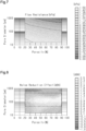
- the flow resistance of the porous member 41 is set based on the pore diameter and porosity of the porous member 41.
- the flow resistance value of the porous member 41 is mapped with respect to the pore diameter and porosity of the porous member 41.
- the long-dash short-dash line indicates the line representing a flow resistance of 0.2kPa.
- the plastic 42A does not easily flow into the porous member 41 during insert molding.
- the region in which the flow resistance of the porous member 41 is greater than or equal to 0.2 kPa not only hinders the flow of the plastic 42A into the porous member 41 during insert molding, but also achieves a desirable pressure increase effect of the fan 30.
- the value of the noise reduction effect of the porous member 41 is mapped with respect to the pore diameter and porosity of the porous member 41.
- the value of the noise reduction effect may be the sound pressure that the porous member 41 can reduce from the noise, for example.
- the porous member 41 can maintain the noise reduction effect.
- the noise reduction effect is quantified as the noise level of a fan 30 with the porous member 41 with respect to the noise level of a fan 30 of the same shape but without the porous member 41.
- the long-dash double-short-dash lines indicate the region in which the flow resistance is greater than or equal to 0.2 kPa, the pore diameter of the porous member 41 is in a range of 50 ⁇ m to 500 ⁇ m, and the porosity of the porous member 41 is in a range of 20% to 90%.
- the noise reduction effect can be maintained, and the fan 30 can also achieve a sufficient pressure increase effect.
- Fig. 9 shows the proportion of the noise reduction effect of the fan component 40 with respect to the MFR of the plastic 42A forming the plastic member 42 for each of the cases in which the flow resistance of porous member 41 is 0.4 kPa, 0.5 kPa, 0.8 kPa, or 1.1 kPa.
- multiple test fans 30 were prepared. Specifically, different test fans 30 were formed using fan components 40 that varied in the flow resistance of the porous member 41 and the MFR of the plastic 42A forming the plastic member 42. The test fans 30 had the same shape.
- the porous members 41 of the fan components 40 forming the test fans 30 were made of the same material but with different flow resistances.
- the plastic members 42 of the fan components 40 forming the test fans 30 were made of the same type of plastic 42A with different MFRs.
- the porous members 41 of the fan components 40 forming the test fans 30 were made of a glass fiber reinforced styrene acrylonitrile plastic (ASG) foam.
- the plastic members 42 of the fan components 40 forming the test fans 30 were made of glass fiber reinforced styrene acrylonitrile plastic (ASG).
- the data in Fig. 9 was obtained by measuring the noise generated by each of the test fans 30 as they rotate.
- the proportion of noise reduction effect in Fig. 9 is the percentage of the value of noise reduction effect of each test fan 30 corresponding to values of MFR of the plastic 42A with respect to the maximum value of noise reduction effect of the test fan 30 in a situation where the flow resistance of the porous member 41 is a predetermined value.
- the maximum value of noise reduction effect is obtained when the MFR of the plastic 42A is 25 g/10 min.
- the noise reduction effect of the fan 30 is about 80% or more of the maximum value of noise reduction effect when the MFR of the plastic 42A is 35 g/10 min.
- the plastic 42A having a greater MFR is more likely to flow into the through-holes of the porous member 41 during insert molding. This tends to lower the noise reduction effect of the fan component 40. In the region in which the flow resistance of the porous member 41 is high and the MFR of the plastic 42A is low, it is difficult to form the fan 30. As such, the noise reduction effect of the fan component 40 may vary.
- the fan component 40 achieves a noise reduction effect when the porous member 41 has a flow resistance in a range of 0.4 kPa to 0.8 kPa and the plastic 42A has an MFR in a range of 2 g/10 min to 45 g/10 min. Furthermore, the fan component 40 obtains a noise reduction effect of 20% or more of the maximum value of noise reduction effect when the flow resistance of the porous member 41 is in a range of 0.4 kPa to 1.1 kPa and the MFR of the plastic 42A is in a range of 5 g/10 min to 40 g/10 min.
- the flow resistance of the porous member 41 of the fan component 40 is in a range of 0.5 kPa to 1.1 kPa, and the MFR of the plastic 42A is in a range of 5 g/10 min to 40 g/10 min, a noise reduction effect of 30% or more of the maximum value of noise reduction effect can be obtained.
- the fan component 40 includes the plastic member 42 made of the plastic 42A having an MFR in a range of 2 g/10 min to 45 g/10 min.
- the plastic 42A with an MFR less than or equal to 45 g/10 min does not easily flow into pores of the porous member 41 during insert molding using the plastic 42A.
- the flow resistance of the porous member 41 is in a range of 0.5 kPa to 1.1 kPa.
- the broken lines indicate a flow resistance of 0.5 kPa and a flow resistance of 1.1kPa.
- the region between the broken lines indicates the range in which the flow resistance is in a range of 0.5 kPa to 1.1 kPa. Since the flow resistance is less than or equal to 1.1 kPa, the plastic 42A flows into the porous member 41 during insert molding using the plastic 42A. As such, in the fan component 40, the porous member 41 and the plastic member 42 are appropriately bonded.
- the porous structure of the porous member 41 is maintained during insert molding using the plastic 42A to the extent that the fan component 40 achieves a noise reduction effect by means of the porous structure.
- the porous member 41 of this embodiment has a flow resistance with which the pore diameter of the porous member 41 is in a range of 50 ⁇ m to 500 ⁇ m and the porosity of the porous member 41 is in a range of 20% to 90%. Since the flow resistance of the porous member 41 is sufficiently high, the plastic 42A does not easily flow into the porous member 41.
- the fan component 40 not only maintains a sufficient noise reduction effect but also resists the flow of plastic 42A into the pores of the porous member 41 during insert molding.
- the porous member 41 of the present embodiment includes the peripheral portion 44.
- the plastic 42A first flows into the peripheral portion 44, and then flows toward the central portion 43 through the peripheral portion 44.
- the peripheral portion 44 has the width D1, and the plastic 42A is therefore unlikely to flow into the central portion 43.
- the plastic 42A flows into the peripheral portion 44, forming the filled-pore portion 45 in the porous member 41. Since the plastic 42A flows into the pores in the filled-pore portion 45, the filled-pore portion 45 appropriately bonds the porous member 41 and the plastic member 42 together.
- the MFR of the plastic 42A is less than or equal to 45 g/10 min, the number of pores in the porous member 41 filled with the plastic 42A is reduced. As a result, the porous member 41 and the plastic member 42 are integrally molded in a suitable manner while maintaining the noise reduction effect of the porous member 41.
- the plastic 42A has an MFR less than or equal to 45 g/10 min, the plastic 42A does not easily flow into the pores of the porous member 41 when the plastic member 42 and the porous member 41 are molded integrally. Since the plastic 42A does not easily flow into the pores of the porous member 41, the pores of the porous member 41 are more likely to be maintained.
- the plastic 42A flows easily into the mold 50, and the injection time during insert molding can be shortened.
- the plastic 42A flows not only into the peripheral portion 44 of the porous member 41 but also into the central portion 43 of the porous member 41 during insert molding. If the plastic 42A flows into the central portion 43 of the porous member 41, pores in the central portion 43 are filled with the plastic 42A, reducing the pores in the porous member 41. The reduced pores in the porous member 41 may lower the noise reduction effect of the porous member 41.
- the plastic 42A having an MFR less than or equal to 45 g/10 min is unlikely to permeate into the central portion 43 of the porous member 41 during insert molding.
- the MFR of the plastic 42A may be in a range of 2 g/10 min to 40 g/10 min. According to this configuration, the plastic 42A does not easily flow into the pores of the porous member 41, so that the pores of the porous member 41 are more likely to be maintained.
- the MFR of the plastic 42A may be in a range of 2 g/10 min to 35 g/10 min. According to this configuration, the plastic 42A does not easily flow into the pores of the porous member 41, so that the pores of the porous member 41 are more likely to be maintained.
- the plastic 42A having an MFR of less than 2 g/10 min does not easily flow within the mold 50 during insert molding, making it difficult to form the fan component 40. It is difficult for the plastic 42A having an excessively low MFR to form the fan component 40 especially when the fan component 40 is thin.
- the MFR of the plastic 42A is greater than or equal to 2 g/10 min, the plastic 42Aflows suitably inside the mold 50 during insert molding, forming the fan component 40 in a suitable manner.
- the MFR of the plastic 42A may be in a range of 5 g/10 min to 45 g/10 min. With this configuration, the plastic 42A more suitably flows within the mold 50 during insert molding, forming the fan component 40 in a more suitable manner.
- the ones to be filled with the plastic 42A are appropriately set. Setting the MFR in this manner improves the bonding strength between the porous member 41 and the plastic member 42 while maintaining the noise reduction effect of the porous structure of the porous member 41.
- the MFR of the plastic 42A is in a range of 5 g/10 min to 40 g/10 min. According to this configuration, since the MFR of the plastic 42A is less than or equal to 40 g/10 min, the number of pores in the porous member 41 filled with the plastic 42A is reduced. When the MFR of plastic 42A is 5 g/10 min or more, the plastic 42A flows suitably within the mold 50 during insert molding, forming the fan component 40 in a more suitable manner.
- the MFR of the plastic 42A may be in a range of 5 g/10 min to 35 g/10 min. According to this configuration, since the MFR of the plastic 42A is less than or equal to 35 g/10 min, the number of pores in the porous member 41 filled with the plastic 42A is reduced. When the MFR of plastic 42A is 5 g/10 min or more, the plastic 42A flows suitably within the mold 50 during insert molding, forming the fan component 40 in a more suitable manner.
- the flow resistance of the porous member 41 is in a range of 0.5 kPa to 1.1 kPa. According to this configuration, since the flow resistance of the porous member 41 is greater than or equal to 0.5 kPa, the number of pores in the porous member 41 filled with the plastic 42A is reduced. At the same time, since the flow resistance of the porous member 41 is less than or equal to 1.1 kPa, pores of the porous member 41 are filled with the plastic 42A to an extent that integrates the porous member 41 and the plastic member 42.
- the porous member 41 of the fan component 40 is in a range of 0.5 kPa to 1.1 kPa, the porous member 41 is molded integrally with the plastic member 42 while maintaining the noise reduction effect of the porous structure.
- the porosity of the porous member 41 is in a range of 20% to 90%, and the pore diameter of the porous member 41 is in a range of 50 ⁇ m to 500 ⁇ m. According to this configuration, since the porosity of the porous member 41 is in a range of 20% to 90%, and the pore diameter of the porous member 41 is in a range of 50 ⁇ m to 500 ⁇ m, the number of pores in the porous member 41 filled with the plastic 42A is reduced.
- An increased flow resistance of the porous member 41 hinders the flow of the plastic 42A into the porous member 41. Since the flow of plastic 42A into the porous member 41 is hindered, the plastic 42A does not easily flow into the pores of the porous member 41. Since the porosity and pore diameter are reduced to increase the flow resistance of the porous member 41, the pores of the porous member 41 are more likely to be maintained when the porous member 41 and the plastic member 42 are integrally molded.
- the porous member 41 that has a porosity in a range of 20% to 90% and a pore diameter in a range of 50 ⁇ m to 500 ⁇ m maintains a noise reduction effect as well as a flow resistance that hinders the flow of the plastic 42A into pores of the porous member 41.
- the porous member 41 that has a pore diameter of less than 50 ⁇ m results in a lower noise reduction effect.
- the porous member 41 that has a pore diameter of greater than 500 ⁇ m has a small flow resistance, facilitating the entry of the plastic 42A into pores of the porous member 41 during insert molding.
- the porous member 41 having a porosity of less than 20% results in a lower noise reduction effect.
- the porous member 41 that has a porosity of greater than 90% has a small flow resistance, facilitating the entry of the plastic 42A into pores of the porous member 41 during insert molding.
- the porosity of the porous member 41 is in a range of 30% to 90%, and the pore diameter of the porous member 41 is in a range of 90 ⁇ m and 300 ⁇ m. According to this configuration, the porosity of the porous member 41 is in a range of 30% to 90%, and the pore diameter of the porous member 41 is in a range of 90 ⁇ m to 300 ⁇ m, so that the number of pores in the porous member 41 filled with the plastic 42A is reduced.
- the porous member 41 includes the filled-pore portion 45.
- the pores in the filled-pore portion 45 of the porous member 41 are filled with the plastic 42A.
- the pores of the porous member 41 are filled with the plastic 42A, so that the porous member 41 and the plastic member 42 are suitably bonded at the filled-pore portion 45.
- the porous member 41 includes the central portion 43 and the peripheral portion 44.
- the flow resistance of the peripheral portion 44 differs from the flow resistance of the central portion 43. According to this configuration, causing the central portion 43 and the peripheral portion 44 of the porous member 41 to have different flow resistances enables suitable management of the manner in which the porous member 41 and the plastic member 42 are bonded. In this embodiment, by causing the peripheral portion 44 to have a greater flow resistance than the central portion 43, it is possible to manage the porous member 41 and the plastic member 42 such that they are bonded only at the peripheral portion 44.
- the fan component 40 includes the porous member 41 and the plastic member 42 molded integrally with the porous member 41.
- the porosity of the porous member 41 may be in a range of 20% to 90%, and the pore diameter of the porous member 41 may be in a range of 50 ⁇ m to 500 ⁇ m. According to this configuration, since the porosity of the porous member 41 is in a range of 20% to 90% and the pore diameter of the porous member 41 is in a range of 50 ⁇ m to 500 ⁇ m, the number of the pores in the porous member 41 filled with the plastic 42A is reduced. As a result, the porous member 41 and the plastic member 42 are integrally molded in a suitable manner while maintaining the noise reduction effect of the porous member 41.
- the fan 30 is formed by the fan component 40. According to this configuration, the fan 30 that is formed by the fan component 40 is provided.
- the fan unit 20 includes the fan 30 and the bellmouth 21. According to this configuration, the fan unit 20 including the fan 30 and the bellmouth 21 is provided.
- the air conditioner 10A includes the fan unit 20. According to this configuration, the air conditioner 10A including the fan unit 20 is provided.
- the method for manufacturing the fan component 40 includes performing insert molding on the porous member 41 having multiple pores with the plastic 42A having an MFR in a range of 2 g/10 min to 45 g/10 min. According to this configuration, since the MFR of the plastic 42A is in a range of 2 g/10 min and 45 g/10 min, the plastic 42A does not easily flow into the pores of the porous member 41 when the porous member 41 undergoes insert molding. Since the plastic 42A does not easily flow into the pores of the porous member 41, the pores of the porous member 41 are more likely to be maintained. By using the plastic member 42 of such an MFR, the porous member 41 is subjected to insert molding in a suitable manner while maintaining the noise reduction effect of the porous member 41.
- the air conditioner, the fan unit, the fan, the fan component, and the method for manufacturing a fan component of the present disclosure may be modified as modifications below or as combinations of at least two modifications that do not contradict each other.
- the air conditioner 10A may be an air purifier.
- the fan unit 20 may form an air inlet or an air outlet of an air purifier.
- an air purifier treats the intake air using a filter, a UV device, an ionizer device, a virus-removing spray device, a streamer device, or the like and then blows it out.
- the air purifier may be configured to treat the air in indoor spaces such as houses, offices, and the like.
- the air purifier may also be configured to treat air in an indoor space, such as a space in a warehouse where articles are stored, a work space where articles are handled, or the like.
- the fan unit 20 may be provided in a heat pump device.
- the heat pump device of this modification includes a fan unit 20.
- the heat pump device may include a refrigerant circuit.
- the heat pump device may be an air conditioner or a water heater. According to this configuration, a heat pump device including the fan unit 20 is provided.
- the member formed by the fan component 40 is not limited to the fan 30.
- the fan component 40 may form the bellmouth 21, and the fan component 40 may form the fan casing 23.
- the fan component 40 may form the air outlet 23A or the support portion 23B.
- the predetermined conditions may be test conditions conforming to ISO 1133-1 or ISO 1133-2.
- the predetermined conditions may be test conditions conforming to JIS K7210-1, JIS K7210-2, or ASTM D1238.
- melt volume-flow rate may be used.
- the MVR is the product of the melt mass flow rate of the plastic 42A and the melt density of the plastic 42A, for example.
- the flow resistance of the peripheral portion 44 may be less than the flow resistance of the central portion 43. According to this configuration, the plastic 42A easily permeates the peripheral portion 44, thereby improving the bonding strength between the porous member 41 and the plastic member 42.
Landscapes
- Engineering & Computer Science (AREA)
- Mechanical Engineering (AREA)
- General Engineering & Computer Science (AREA)
- Manufacturing & Machinery (AREA)
- Structures Of Non-Positive Displacement Pumps (AREA)
Applications Claiming Priority (3)
| Application Number | Priority Date | Filing Date | Title |
|---|---|---|---|
| JP2023059491 | 2023-03-31 | ||
| JP2023167785 | 2023-09-28 | ||
| PCT/JP2024/012925 WO2024204662A1 (ja) | 2023-03-31 | 2024-03-28 | ファン用部材、ファン、ファンユニット、空気調和機、ヒートポンプ装置、及びファン用部材の製造方法 |
Publications (2)
| Publication Number | Publication Date |
|---|---|
| EP4461968A1 true EP4461968A1 (de) | 2024-11-13 |
| EP4461968A4 EP4461968A4 (de) | 2025-06-11 |
Family
ID=92424188
Family Applications (1)
| Application Number | Title | Priority Date | Filing Date |
|---|---|---|---|
| EP24747970.2A Pending EP4461968A4 (de) | 2023-03-31 | 2024-03-28 | Gebläseelement, gebläseeinheit, klimaanlage, wärmepumpenvorrichtung und verfahren zur herstellung eines gebläseelements |
Country Status (5)
| Country | Link |
|---|---|
| US (1) | US20260009405A1 (de) |
| EP (1) | EP4461968A4 (de) |
| JP (1) | JP7606149B2 (de) |
| CN (1) | CN120981663A (de) |
| WO (1) | WO2024204662A1 (de) |
Family Cites Families (9)
| Publication number | Priority date | Publication date | Assignee | Title |
|---|---|---|---|---|
| JP2754862B2 (ja) | 1990-04-27 | 1998-05-20 | 松下電器産業株式会社 | 送風機羽根車 |
| JPH0625597U (ja) | 1992-09-03 | 1994-04-08 | 太平洋工業株式会社 | 軸流ファンのファンシュラウド |
| JP2950449B2 (ja) * | 1992-12-11 | 1999-09-20 | 大宝工業株式会社 | 射出成形金型およびその金型を使用した合成樹脂成形体の製造方法 |
| JP4276363B2 (ja) * | 2000-07-31 | 2009-06-10 | 株式会社小松製作所 | ファン装置の騒音低減機構に用いられる多孔質吸音材の成形方法 |
| JP2005052234A (ja) * | 2003-08-07 | 2005-03-03 | Mitsubishi Materials Corp | ファン型空気清浄器及びこれに用いられる羽根部の製造方法 |
| JP2005155437A (ja) * | 2003-11-26 | 2005-06-16 | Matsushita Electric Ind Co Ltd | 送風機用羽根車 |
| JP5190045B2 (ja) * | 2009-11-11 | 2013-04-24 | 株式会社日立製作所 | 多孔質体に充填された樹脂中に発生するボイド体積変化の予測方法 |
| JP5331675B2 (ja) * | 2009-12-28 | 2013-10-30 | 株式会社日立製作所 | 多孔質体の流動抵抗値算出方法及びその装置 |
| JP2021134751A (ja) | 2020-02-28 | 2021-09-13 | 公立大学法人 富山県立大学 | ファンユニット及びこれを用いた送風機 |
-
2024
- 2024-03-28 CN CN202480021662.9A patent/CN120981663A/zh active Pending
- 2024-03-28 JP JP2024053224A patent/JP7606149B2/ja active Active
- 2024-03-28 EP EP24747970.2A patent/EP4461968A4/de active Pending
- 2024-03-28 WO PCT/JP2024/012925 patent/WO2024204662A1/ja not_active Ceased
-
2025
- 2025-09-10 US US19/325,260 patent/US20260009405A1/en active Pending
Also Published As
| Publication number | Publication date |
|---|---|
| JP2024146879A (ja) | 2024-10-15 |
| WO2024204662A1 (ja) | 2024-10-03 |
| JP7606149B2 (ja) | 2024-12-25 |
| EP4461968A4 (de) | 2025-06-11 |
| US20260009405A1 (en) | 2026-01-08 |
| CN120981663A (zh) | 2025-11-18 |
Similar Documents
| Publication | Publication Date | Title |
|---|---|---|
| CN105698285B (zh) | 压缩机组件、室外机及空调器 | |
| CN104236200A (zh) | 风冷冰箱及其风道 | |
| US20260009405A1 (en) | Fan component, fan, fan unit, air conditioner, heat pump device, and method for manufacturing fan component | |
| CN104870254B (zh) | 运输制冷装置内的冷凝器排气风扇位置 | |
| US20240288295A1 (en) | Dust filter for gas meter | |
| CN202851208U (zh) | 消音器 | |
| CN206046057U (zh) | 步入式高温高湿试验箱 | |
| CN106089805B (zh) | 一种空气净化器的气流驱动装置 | |
| CN210688801U (zh) | 空调系统 | |
| CN103453700B (zh) | 闪蒸器及包括该闪蒸器的空调 | |
| CN207974956U (zh) | 涡旋压缩机及具有其的空调器 | |
| CN218421915U (zh) | 制氧机 | |
| CN205448071U (zh) | 压缩机组件、室外机及空调器 | |
| CN205641704U (zh) | 过滤器 | |
| CN212803684U (zh) | 一种风机、风管内机及空调 | |
| CN207122396U (zh) | 用于压缩机的消音器和具有其的压缩机 | |
| CN207922642U (zh) | 一种用于制冷压缩机的油分离器 | |
| CN207849835U (zh) | 空调用油分离器、冷凝器和空调器 | |
| CN104344528B (zh) | 空调壳体及柜式空调 | |
| CN105698283A (zh) | 压缩机组件、室外机及空调器 | |
| CN207333142U (zh) | 压缩机组件 | |
| CN208380851U (zh) | 压缩机的增焓结构及涡旋压缩机 | |
| CN205939842U (zh) | 一种自动检测气密性的储液干燥瓶 | |
| CN206222542U (zh) | 空调室外机的降噪装置及空调室外机 | |
| CN105698286A (zh) | 压缩机组件、室外机和压缩机组件的制造工艺 |
Legal Events
| Date | Code | Title | Description |
|---|---|---|---|
| STAA | Information on the status of an ep patent application or granted ep patent |
Free format text: STATUS: UNKNOWN |
|
| STAA | Information on the status of an ep patent application or granted ep patent |
Free format text: STATUS: THE INTERNATIONAL PUBLICATION HAS BEEN MADE |
|
| PUAI | Public reference made under article 153(3) epc to a published international application that has entered the european phase |
Free format text: ORIGINAL CODE: 0009012 |
|
| STAA | Information on the status of an ep patent application or granted ep patent |
Free format text: STATUS: REQUEST FOR EXAMINATION WAS MADE |
|
| 17P | Request for examination filed |
Effective date: 20240805 |
|
| AK | Designated contracting states |
Kind code of ref document: A1 Designated state(s): AL AT BE BG CH CY CZ DE DK EE ES FI FR GB GR HR HU IE IS IT LI LT LU LV MC ME MK MT NL NO PL PT RO RS SE SI SK SM TR |
|
| P01 | Opt-out of the competence of the unified patent court (upc) registered |
Free format text: CASE NUMBER: APP_1089/2025 Effective date: 20250108 |
|
| A4 | Supplementary search report drawn up and despatched |
Effective date: 20250512 |
|
| RIC1 | Information provided on ipc code assigned before grant |
Ipc: F04D 29/66 20060101ALI20250506BHEP Ipc: F04D 29/02 20060101ALI20250506BHEP Ipc: B29C 45/14 20060101ALI20250506BHEP Ipc: F04D 29/38 20060101AFI20250506BHEP |
|
| STAA | Information on the status of an ep patent application or granted ep patent |
Free format text: STATUS: EXAMINATION IS IN PROGRESS |
|
| 17Q | First examination report despatched |
Effective date: 20260128 |