EP4458583B1 - Industrielle druckvorrichtung und industrielles druckverfahren - Google Patents
Industrielle druckvorrichtung und industrielles druckverfahren Download PDFInfo
- Publication number
- EP4458583B1 EP4458583B1 EP23171085.6A EP23171085A EP4458583B1 EP 4458583 B1 EP4458583 B1 EP 4458583B1 EP 23171085 A EP23171085 A EP 23171085A EP 4458583 B1 EP4458583 B1 EP 4458583B1
- Authority
- EP
- European Patent Office
- Prior art keywords
- stage
- printing device
- industrial printing
- cutting
- printer
- Prior art date
- Legal status (The legal status is an assumption and is not a legal conclusion. Google has not performed a legal analysis and makes no representation as to the accuracy of the status listed.)
- Active
Links
Images

Classifications
-
- B—PERFORMING OPERATIONS; TRANSPORTING
- B41—PRINTING; LINING MACHINES; TYPEWRITERS; STAMPS
- B41J—TYPEWRITERS; SELECTIVE PRINTING MECHANISMS, i.e. MECHANISMS PRINTING OTHERWISE THAN FROM A FORME; CORRECTION OF TYPOGRAPHICAL ERRORS
- B41J2/00—Typewriters or selective printing mechanisms characterised by the printing or marking process for which they are designed
- B41J2/005—Typewriters or selective printing mechanisms characterised by the printing or marking process for which they are designed characterised by bringing liquid or particles selectively into contact with a printing material
- B41J2/01—Ink jet
-
- B—PERFORMING OPERATIONS; TRANSPORTING
- B41—PRINTING; LINING MACHINES; TYPEWRITERS; STAMPS
- B41J—TYPEWRITERS; SELECTIVE PRINTING MECHANISMS, i.e. MECHANISMS PRINTING OTHERWISE THAN FROM A FORME; CORRECTION OF TYPOGRAPHICAL ERRORS
- B41J11/00—Devices or arrangements of selective printing mechanisms, e.g. ink-jet printers or thermal printers, for supporting or handling copy material in sheet or web form
- B41J11/66—Applications of cutting devices
- B41J11/663—Controlling cutting, cutting resulting in special shapes of the cutting line, e.g. controlling cutting positions, e.g. for cutting in the immediate vicinity of a printed image
-
- B—PERFORMING OPERATIONS; TRANSPORTING
- B41—PRINTING; LINING MACHINES; TYPEWRITERS; STAMPS
- B41F—PRINTING MACHINES OR PRESSES
- B41F19/00—Apparatus or machines for carrying out printing operations combined with other operations
- B41F19/008—Apparatus or machines for carrying out printing operations combined with other operations with means for stamping or cutting out
-
- B—PERFORMING OPERATIONS; TRANSPORTING
- B23—MACHINE TOOLS; METAL-WORKING NOT OTHERWISE PROVIDED FOR
- B23K—SOLDERING OR UNSOLDERING; WELDING; CLADDING OR PLATING BY SOLDERING OR WELDING; CUTTING BY APPLYING HEAT LOCALLY, e.g. FLAME CUTTING; WORKING BY LASER BEAM
- B23K26/00—Working by laser beam, e.g. welding, cutting or boring
- B23K26/36—Removing material
- B23K26/38—Removing material by boring or cutting
-
- B—PERFORMING OPERATIONS; TRANSPORTING
- B26—HAND CUTTING TOOLS; CUTTING; SEVERING
- B26D—CUTTING; DETAILS COMMON TO MACHINES FOR PERFORATING, PUNCHING, CUTTING-OUT, STAMPING-OUT OR SEVERING
- B26D7/00—Details of apparatus for cutting, cutting-out, stamping-out, punching, perforating, or severing by means other than cutting
- B26D7/06—Arrangements for feeding or delivering work of other than sheet, web, or filamentary form
-
- B—PERFORMING OPERATIONS; TRANSPORTING
- B26—HAND CUTTING TOOLS; CUTTING; SEVERING
- B26D—CUTTING; DETAILS COMMON TO MACHINES FOR PERFORATING, PUNCHING, CUTTING-OUT, STAMPING-OUT OR SEVERING
- B26D7/00—Details of apparatus for cutting, cutting-out, stamping-out, punching, perforating, or severing by means other than cutting
- B26D7/18—Means for removing cut-out material or waste
-
- B—PERFORMING OPERATIONS; TRANSPORTING
- B26—HAND CUTTING TOOLS; CUTTING; SEVERING
- B26F—PERFORATING; PUNCHING; CUTTING-OUT; STAMPING-OUT; SEVERING BY MEANS OTHER THAN CUTTING
- B26F3/00—Severing by means other than cutting; Apparatus therefor
- B26F3/002—Precutting and tensioning or breaking
-
- B—PERFORMING OPERATIONS; TRANSPORTING
- B41—PRINTING; LINING MACHINES; TYPEWRITERS; STAMPS
- B41F—PRINTING MACHINES OR PRESSES
- B41F13/00—Common details of rotary presses or machines
- B41F13/54—Auxiliary folding, cutting, collecting or depositing of sheets or webs
- B41F13/56—Folding or cutting
- B41F13/58—Folding or cutting lengthwise
-
- B—PERFORMING OPERATIONS; TRANSPORTING
- B41—PRINTING; LINING MACHINES; TYPEWRITERS; STAMPS
- B41J—TYPEWRITERS; SELECTIVE PRINTING MECHANISMS, i.e. MECHANISMS PRINTING OTHERWISE THAN FROM A FORME; CORRECTION OF TYPOGRAPHICAL ERRORS
- B41J11/00—Devices or arrangements of selective printing mechanisms, e.g. ink-jet printers or thermal printers, for supporting or handling copy material in sheet or web form
- B41J11/0015—Devices or arrangements of selective printing mechanisms, e.g. ink-jet printers or thermal printers, for supporting or handling copy material in sheet or web form for treating before, during or after printing or for uniform coating or laminating the copy material before or after printing
-
- B—PERFORMING OPERATIONS; TRANSPORTING
- B41—PRINTING; LINING MACHINES; TYPEWRITERS; STAMPS
- B41J—TYPEWRITERS; SELECTIVE PRINTING MECHANISMS, i.e. MECHANISMS PRINTING OTHERWISE THAN FROM A FORME; CORRECTION OF TYPOGRAPHICAL ERRORS
- B41J11/00—Devices or arrangements of selective printing mechanisms, e.g. ink-jet printers or thermal printers, for supporting or handling copy material in sheet or web form
- B41J11/66—Applications of cutting devices
-
- B—PERFORMING OPERATIONS; TRANSPORTING
- B41—PRINTING; LINING MACHINES; TYPEWRITERS; STAMPS
- B41J—TYPEWRITERS; SELECTIVE PRINTING MECHANISMS, i.e. MECHANISMS PRINTING OTHERWISE THAN FROM A FORME; CORRECTION OF TYPOGRAPHICAL ERRORS
- B41J15/00—Devices or arrangements of selective printing mechanisms, e.g. ink-jet printers or thermal printers, specially adapted for supporting or handling copy material in continuous form, e.g. webs
- B41J15/04—Supporting, feeding, or guiding devices; Mountings for web rolls or spindles
-
- B—PERFORMING OPERATIONS; TRANSPORTING
- B41—PRINTING; LINING MACHINES; TYPEWRITERS; STAMPS
- B41J—TYPEWRITERS; SELECTIVE PRINTING MECHANISMS, i.e. MECHANISMS PRINTING OTHERWISE THAN FROM A FORME; CORRECTION OF TYPOGRAPHICAL ERRORS
- B41J29/00—Details of, or accessories for, typewriters or selective printing mechanisms not otherwise provided for
- B41J29/17—Cleaning arrangements
-
- B—PERFORMING OPERATIONS; TRANSPORTING
- B41—PRINTING; LINING MACHINES; TYPEWRITERS; STAMPS
- B41J—TYPEWRITERS; SELECTIVE PRINTING MECHANISMS, i.e. MECHANISMS PRINTING OTHERWISE THAN FROM A FORME; CORRECTION OF TYPOGRAPHICAL ERRORS
- B41J15/00—Devices or arrangements of selective printing mechanisms, e.g. ink-jet printers or thermal printers, specially adapted for supporting or handling copy material in continuous form, e.g. webs
- B41J15/16—Means for tensioning or winding the web
- B41J15/165—Means for tensioning or winding the web for tensioning continuous copy material by use of redirecting rollers or redirecting nonrevolving guides
Definitions
- the present invention generally relates to an industrial printing device and an industrial printing process.
- Industrial printing devices are known to continuously print material according to a predetermined layout at high printing speeds (professional printing speeds).
- the material is provided as a continuous web of material where only certain portions are printed.
- die-cutting tools subsequent to the printing process such that the material is cut.
- a portion of the processed material may remain uncut (kiss cutting technique) for transportation purposes along the production line and a matrix layer may be removed to reveal only the final product on the release layer of the processed material.
- the die-cutting tools may either be implemented with the printing devices at separate die-cutting stages downstream of the printer stage or, in an alternative, the printed band of material may be provided to separate die-cutting devices, also called finishing devices.
- laser cutting tools are known nowadays. Therefore, some manufactures provide separate laser cutting tools (finishing tools) to which the printed material is provided subsequent to the printing process. However, in this case two separate devices are required. Also, the transfer of the printed band of material to the separate laser cutting devices is time consuming and requires repeated registration adjustments such that high investments for the separate devices are caused and the manufacturing efficiency is limited.
- US 2017/0182807 A1 discloses a combined printing and laser cutting device.
- the laser cutting stage is arranged subsequent to the printing stage. Therefore, after cutting the underlying material cut edges are established which are not printed, i.e. not covered by any ink. As a consequence, the quality of the manufactured products, such as labels, is limited.
- US 2008/074453 A1 discloses relevant prior art for the present invention.
- the objective technical problem to be solved may be considered to consist in overcoming or at least reducing the disadvantages according to the prior art.
- an industrial printing device is desired, which is capable of providing printed cut edges that are producible for various different printing layouts at low manufacturing expenses.
- an industrial printing device comprises at least an input stage, an output stage, a cutting stage, and a printer stage.
- the printer stage is arranged between the input stage and the output stage.
- the cutting stage is arranged upstream of the printer stage.
- the industrial printing device is characterized in that the cutting stage comprises a laser cutting device such that material is continuously processable between the input stage and the output stage by at least the cutting stage and the printer stage.
- the cutting stage is arranged upstream of the printer stage, the material is cut first and subsequently printed. This provides the possibility to also print edges of the cut material for high-quality printed layouts. Therefore, the industrial printer device is configured for a greater variety of applications, such as e.g. for high-quality wine labels having printed edges.
- the laser cutting device ensures that a wide variety of cutting layouts may be guaranteed without the need of manufacturing different cutting tools in this regard.
- complex cutting layouts may be considered which, due to their complexity, may not be readily producible by mechanical die-cutting procedures.
- laser cutting devices are also capable of performing micro cuts and small step spacing such as for perforations, which is not readily achievable by mechanical die-cutting procedures at similar qualities.
- a change from a first cutting layout to a different second cutting layout may be performed on-the-fly without any interruption of the procedure carried out by means of the industrial printing device.
- the cutting device is not required to deal with varying material thicknesses.
- a varying ink thickness is established on the material leading to an overall varying material thickness.
- the power used during laser-based cutting procedures is always desired to be optimized to the lowest possible value in order to avoid excessive local heating of the underlying materials during the cutting procedure as best as possible. Therefore, unwanted local burning effects can be avoided.
- the cutting device may be operated at a homogeneous power since the material thickness is homogeneous and does not show any variations due to ink.
- the cutting procedure applied in view of the laser cutting device can be reliably performed from a side of the processed material which represents the front side of the later finished product.
- the specific arrangement of the laser cutting device cutting the processed material from the front side ensures that the finished products may also comprise high-quality haptics properties.
- a wide variety of adhesives and inks causes smoke and debris to be released by the cutting procedure if these substances are treated by a laser cutting device. Accordingly, arranging the printer stage subsequent to the cutting stage also assists in reducing the amount of smoke and debris to be released as the treated material is not yet printed when applying the cutting procedure.
- an industrial printing device may also be considered a professional printing device.
- the industrial printing device may be configured to execute professional printing services.
- Professional printing services may be considered to not represent home use applications, but to represent printing procedures where the underlying printing layout comprises a resolution of substantially 1200 dpi (dots per inch) or higher.
- the input stage may be considered a section of the industrial printing device, where raw material to be cut and to be printed is provided.
- the treated material is continuously collected at the output stage.
- the finished material may be removed from the printing device.
- a priming stage is arranged downstream of the cutting stage and upstream of the printer stage.
- the priming stage may be used to apply a ground coat to the cut material.
- the cut material may be prepared such that ink provided by the printer stage appropriately adheres to the ground coated material without any smearing. Therefore, high-quality printed products may be achieved.
- the processed material when being cut at the cutting stage, is not required to already comprise a lamination material layer.
- the processed material may generally comprise various material layers, such as a printable material layer and a lamination material layer for wear resistance. Even if the material would comprise several material layers, it would be possible to in principle cut the material by a laser cutting device. However, treatment of a lamination material layer by a laser cutting device may potentially lead to unwanted local burning effects especially at the laminated cut edges.
- One measure to circumvent this problem in case of already printed material at known finishing devices is to unravel the lamination material layer from a remainder of the processed material, subsequently cut the remainder of the material, and laminate the cut material again.
- such complex procedures may be avoided in the present case, as the cutting stage is arranged upstream of the printer stage and as the priming stage is provided only downstream of the cutting stage. Therefore, local burning effects may be avoided as the material processed at the cutting stage is not required to already comprise a lamination layer.
- the priming stage is at least configured to prime cut edges of the material such that the primed cut edges of the material are printable. Without the cut edges being primed, ink provided to the cut edges may smear over such that the quality of the printed products is limited.
- the priming stage is arranged subsequent to the cutting stage, the cut material is coated with the ground coat also in view of cut edges established by the cutting process. Accordingly, the ink provided by the printer stage may also appropriately adhere to the cut edges having the ground coat according to the respective needs. Hence, the quality of the printed products is additionally improved.
- a web cleaning stage is provided downstream of the cutting stage and upstream of the priming stage.
- impurities caused by the cutting process such as due to released smoke or debris, may be removed before the ground coat is applied. Therefore, it may be avoided that impurities are already included within the coating of the ground coat. This leads to an additional improvement of the overall quality of the printed products.
- a buffer stage is provided downstream of the web cleaning stage and upstream of the priming stage. Since the material is continuously processed within the industrial printing device, the buffer stage may provide for a sufficient time period of the processed material to cool down before the ground coat is applied within the priming stage.
- the buffer system also allows time for the laser system to process and load the next cutting file, while the printing of the previous job may continue at different processing.
- the web cleaning stage may apply fluid cleaning substances.
- the buffer stage may provide for a sufficient time period for the cleaning substances to volatilize from the cleaned portions of material. Therefore, it is ensured that the ground coat is applied directly to the clean material and is not affected by any other substances or, in an alternative, is applied to the material having an inappropriately high temperature.
- buffer stages may be provided at different locations between the input stage and the output stage according to the respective needs.
- the industrial printing device comprises a single motion control device configured to control a motion of the material guided through different stages of the industrial printing device.
- a single motion control device configured to control a motion of the material guided through different stages of the industrial printing device.
- the single motion control is configured to ensure a registration between the material and the cutting stage.
- An accurate registration between the underlying material and the cutting stage ensures that the high precision provided by the laser cutting device is best made use of. Accordingly, high-quality cut blanks of the material are established.
- the same motion control device is applied for registration in view of the cutting procedure and the remaining treatments provided within the industrial printing device.
- the material is guided at a constant speed through the different stages of the industrial printing device. This means that the material is not needed to be slowed down for cutting the material by means of the laser cutting device. Rather, the laser cutting device is configured and arranged so as to cut the processed material at a speed which is equivalent to the printing speed provided by the printer stage.
- the laser cutting device is configured and arranged so as to cut the processed material at a speed which is equivalent to the printing speed provided by the printer stage.
- a wide variety of cutting layouts is producible and printable without any need for a reduction of the production speed. Even further, compared to classic mechanical die-cutting procedures, no downtimes are required for changing the underlying cutting tools of the cutting stage.
- the motion control device comprises a unified tension control for the material throughout different stages of the industrial printing device. Therefore, it is ensured that the material is processed within the entire industrial printing device having applied a unified tension thereto at different stages of the printing device. Thereby, side effects such as stretching of the material are required to be considered only once since the tension applied to the processed material is homogeneous along the entire printing device.
- a closed loop registration system could be used to maintain constant registration along and across the media.
- This closed loop could be based on image scanning or printed registration marks that sensors would read and the imaging processor could move or scale the image to match the cutting, if needed.
- This is a significant advantage of having the process inline (upstream or downstream). Nevertheless, in our case, the printing can start only of the die cutting has match the scanning requirement, in order to drive the ink waste to minimum.
- the printer stage comprises a flex or digital inkjet printer device.
- These printer devices provide high-quality printed products.
- a digital inkjet printer device may be preferred if a contactless printing procedure is desired.
- thermobonding material may be applied for specific use cases.
- the choice of the underlying printer device may also be motivated by the desired type of raw material to be processed.
- a cold foil stage may be provided downstream of the priming stage and upstream of the printer stage.
- a cold foil may then be applied to the primed cut material, e.g. for enlarging the material thickness before printing. This may be desired in case of specific applications so as to achieve robust printed products.
- a roll of blank (raw) material is provided at the input stage. Therefore, as long as blank material is still available at the input stage, the industrial printing device may continuously treat the processed material.
- a roll of finished material is collected at the output stage.
- the cut and printed products also named blanks
- the cut and printed products may be removed from a remainder of the processed material.
- a role of waste material is collected at the output stage, whereas the blanks may be removed from the industrial printing device through a separate outlet.
- downstream of the printer stage and upstream of the output stage at least one or any combination of an analog or digital embellishment stage, a varnish stage, and a matrix rewinding stage is provided downstream of the printer stage. Accordingly, a finishing procedure may be provided to the printed products at the embellishment stage. Also, certain portions of the processed material, such as an underlying matrix may be collected at the matrix rewinding stage. In addition, a varnish may be provided so as to prevent the printed products from being damaged easily. Put differently, the varnish may provide a certain level of wear resistance.
- the industrial printing device may be configured to continuously provide cut and printed layouts at the output stage at a predefined minimum printing speed.
- the material is guided through the industrial printing device at a minimum speed of more than 30 m/min.
- the minimum speed is at least 50 m/min. More preferably, the minimum printing speed is at least 60 m/min. More preferably, the minimum printing speed is substantially 80 m/min. More preferably, the minimum printing speed is substantially 100 m/min.
- an industrial printing process performed by an industrial printing device comprises at least the following steps:
- the industrial printing process makes use of an industrial printing device as described herein before.
- Fig. 1 is a schematic drawing of an industrial printing device 10 according to an embodiment.
- the industrial printing device 10 comprises an input stage 12, an output stage 14, a band of processed material 16, a cutting stage 18, and a printer stage 20.
- the cutting stage 18 and the printer stage 20 are arranged between the input stage 12 and the output stage 14. More specifically, the cutting stage 18 is arranged upstream of the printer stage 20 meaning that the processed material 16 is first treated by the cutting stage 18 and only then treated by the printer stage 20.
- a roll of raw (blank) material 22 is provided at the input stage 12. This material is processed as band of material 16 between the input stage 12 and the output stage 14.
- the finished material 24 may also not be collected as a roll, but may also be collected differently, such as a stack of individual printed products.
- the cutting stage 18 comprises a laser cutting device 19.
- the printer stage 20 comprises a flex or digital inkjet printer device 21.
- the industrial printing device 10 also comprises a single motion control device 26, which is configured to guarantee a registration of the processed material 16 with devices of the various stages of the industrial printing device 10. Therefore, the processed material 16 is appropriately aligned for any treatment by devices of the stages, such as the laser cutting device 19 or the printer device 21. As only a single motion control device 26 is provided, the registration is ensured along the entire industrial printing device 10 meaning that the alignment has to be adjusted only once when setting up the machine.
- the present industrial printing device 10 also comprises a generally optional priming stage 28, which is arranged downstream of the cutting stage 18 and upstream of the printer stage 20.
- the priming stage 28 is configured to apply a ground coat to the processed material 16 after the material 16 is cut at the cutting stage 18.
- the industrial printing device 10 also comprises additional, generally optional, stages, such as a web cleaning stage 30, a buffer stage 32, a cold foil stage 34, an analog or digital embellishment stage 36, a varnish stage 38, and a matrix rewinding stage 40.
- the web cleaning stage 30 is arranged downstream and subsequent to the cutting stage 18 while the buffer stage is arranged next to the web cleaning stage 30 and before the priming stage 28.
- the cold foil stage 34 is arranged between the priming stage 28 and the printer stage 20, the cold foil stage 34 is arranged.
- the digital embellishment stage 36, the varnish stage 38, and the matrix rewinding stage 40 are arranged downstream thereof.
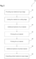
- Fig. 2 is a schematic drawing of an industrial printing process 42 according to an embodiment. Optional steps are shown using dashed lines.
- step 44 raw (blank) material 22 is provided at the input stage 12 of the industrial printing device 10.
- this raw (blank) material 22 is transported through the industrial printing device 10 representing processed material 16.
- step 46 the material 16 is cut at the cutting stage 18 of the industrial printing device 10 using a laser cutting device 19.
- the cut material 16 is printed at the printer stage 20 of the industrial printing device 10.
- the printed material 16 is outputted at the output stage 14 of the industrial printing device 10.
- the cut edges of the material 16 may be printed as well.
- various different cutting layouts may be considered for cutting the material 16.
- the cutting layouts may be varied during the processing of the material 16, i.e. the process 42 may include on-the-fly modifications of the cutting layout applied by the cutting stage 18. Accordingly, high-quality printed products may be achieved at low manufacturing expenses since no downtimes of the underlying industrial printing device 10 are required for changing between different cutting layouts. Also, no different cutting tools are required to be manufactured.
- the process 42 may also comprise one or several additional, generally optional, steps.
- a ground coat may be applied at the priming stage 28 to the cut material 16.
- ink applied by the printer stage 20 may better adhere to the primed material 16 compared to the case of omitting a ground coat.
- the ground coat may ensure that the ink also appropriately adheres to the cut edges of the cut material 16 such the quality of the printed products may be even improved.
- the ground coat may prevent applied ink from smearing over across the material 16.
- step 54 at least one additional treatment may be applied to the processed material 16.
- at least one or multiple of the web cleaning stage 30, the buffer stage 32, or the cold foil stage 34 may be applied.
- the optional step 54 would be conducted subsequent to step 52, i.e. the treatment applied by the priming stage 28.
- treatments by the web cleaning stage 30 and the buffer stage 32 are generally applied prior to the treatment by the priming stage 28 in step 52.
- the process 42 may also comprise additional optional treatment steps after the material 16 is printed in step 48.
- one or multiple of the analog or digital embellishment stage 36, the varnish stage 38, and the matrix rewinding stage 40 may be applied.
- the phrase "at least one of A, B, and C", for example, means (A), (B), (C), (A and B), (A and C), (B and C), or (A, B, and C), including all further possible permutations when greater than three elements are listed.
- the term “at least one of A and B” generally means “A and/or B", namely "A” alone, “B” alone or "A and B”.
Landscapes
- Engineering & Computer Science (AREA)
- Mechanical Engineering (AREA)
- Life Sciences & Earth Sciences (AREA)
- Forests & Forestry (AREA)
- Physics & Mathematics (AREA)
- Optics & Photonics (AREA)
- Plasma & Fusion (AREA)
- Handling Of Sheets (AREA)
- Laser Beam Processing (AREA)
Claims (15)
- Industrielle Druckvorrichtung (10), die zumindest eine Eingabestufe (12), eine Ausgabestufe (14), eine Schneidestufe (18) und eine Druckerstufe (20) umfasst,wobei die Druckerstufe (20) zwischen der Eingabestufe (12) und der Ausgabestufe (14) angeordnet ist, wobei die Schneidestufe (18) stromaufwärts der Druckerstufe (20) angeordnet ist,wobei die Schneidestufe (18) eine Laserschneidvorrichtung (19) umfasst, so dass Material (16) zwischen der Eingabestufe (12) und der Ausgabestufe (14) durch zumindest die Schneidestufe (18) und die Druckerstufe (20) kontinuierlich verarbeitbar ist.
- Industrielle Druckvorrichtung (10) nach Anspruch 1, die eine Grundierungsstufe (28) umfasst, die stromabwärts der Schneidestufe (18) und stromaufwärts der Druckstufe (20) angeordnet ist.
- Industrielle Druckvorrichtung (10) nach Anspruch 2, wobei die Grundierungsstufe (28) zumindest dazu konfiguriert ist, Schnittkanten des Materials (16) so zu grundieren, dass die grundierten Schnittkanten des Materials (16) bedruckbar sind.
- Industrielle Druckvorrichtung (10) nach Anspruch 1 oder 2, wobei eine Bahnreinigungsstufe (30) stromabwärts der Schneidestufe (18) und stromaufwärts der Grundierungsstufe (28) bereitgestellt ist.
- Industrielle Druckvorrichtung (10) nach Anspruch 4, wobei eine Pufferstufe (32) stromabwärts der Bahnreinigungsstufe (30) und stromaufwärts der Grundierungsstufe (28) bereitgestellt ist.
- Industrielle Druckvorrichtung (10) nach einem der vorstehenden Ansprüche, die eine einzelne Bewegungssteuerungsvorrichtung (26) umfasst, die dazu konfiguriert ist, eine Bewegung des Materials (16) zu steuern, das durch verschiedene Stufen der industriellen Druckvorrichtung (10) geführt wird.
- Industrielle Druckvorrichtung (10) nach Anspruch 6, wobei die einzelne Bewegungssteuerungsvorrichtung (26) dazu konfiguriert ist, eine Ausrichtung zwischen dem Material (16) und der Schneidestufe (18) sicherzustellen.
- Industrielle Druckvorrichtung (10) nach Anspruch 6 oder 7, wobei das Material (16) mit einer konstanten Geschwindigkeit durch die verschiedenen Stufen der industriellen Druckvorrichtung (10) geführt wird.
- Industrielle Druckvorrichtung (10) nach einem der Ansprüche 6 bis 8, wobei die Bewegungssteuerungsvorrichtung (26) eine einheitliche Spannungssteuerung für das Material (16) in allen verschiedenen Stufen der industriellen Druckvorrichtung (10) umfasst.
- Industrielle Druckvorrichtung (10) nach einem der vorstehenden Ansprüche, wobei die Druckerstufe (20) eine Flex- oder digitale Tintenstrahldruckvorrichtung (21) umfasst.
- Industrielle Druckvorrichtung (10) nach einem der vorstehenden Ansprüche, wobei an der Eingabestufe (12) eine Rolle unbedruckten Materials (22) bereitgestellt wird und an der Ausgabestufe (14) eine Rolle fertigen Materials (24) gesammelt wird.
- Industrielle Druckvorrichtung (10) nach einem der vorstehenden Ansprüche, wobei stromabwärts der Druckerstufe (20) und stromaufwärts der Ausgabestufe (14) zumindest eine einer analogen oder digitalen Verschönerungsstufe (36), einer Lackstufe (38) und einer Matrixrückspulstufe (40) bereitgestellt ist.
- Industrielle Druckvorrichtung (10) nach einem der vorstehenden Ansprüche, wobei das Material (16) mit einer Mindestgeschwindigkeit von 30 m pro Minute, bevorzugt mit einer Mindestgeschwindigkeit von 50 m pro Minute, bevorzugter mit einer Mindestgeschwindigkeit von 60 m pro Minute, bevorzugter mit einer Mindestgeschwindigkeit von 80 m pro Minute, bevorzugter mit einer Mindestgeschwindigkeit von 100 m pro Minute durch die industrielle Druckvorrichtung (10) geführt wird.
- Industrieller Druckprozess (42), der von einer industriellen Druckvorrichtung (10) durchgeführt wird, umfassend zumindest die folgenden Schritte:- Bereitstellen von Material (16) an einer Eingabestufe (12) der industriellen Druckvorrichtung (10),- Schneiden des Materials (16) an einer Schneidestufe (18) der industriellen Druckvorrichtung (10) mittels einer Laserschneidvorrichtung (19),- Bedrucken des geschnittenen Materials (16) in einer Druckerstufe (20) der industriellen Druckvorrichtung (10) und- Ausgeben von Druckmaterial (16) an einer Ausgabestufe (14) der industriellen Druckvorrichtung (10).
- Industrieller Druckprozess nach Anspruch 14, wobei die industrielle Druckvorrichtung (10) nach einem der Ansprüche 1 bis 13 ist.
Priority Applications (4)
| Application Number | Priority Date | Filing Date | Title |
|---|---|---|---|
| ES23171085T ES3033671T3 (en) | 2023-05-02 | 2023-05-02 | Industrial printing device and industrial printing process |
| EP23171085.6A EP4458583B1 (de) | 2023-05-02 | 2023-05-02 | Industrielle druckvorrichtung und industrielles druckverfahren |
| US18/643,148 US20240367431A1 (en) | 2023-05-02 | 2024-04-23 | Industrial printing device and industrial printing process |
| CN202410530120.6A CN118893909A (zh) | 2023-05-02 | 2024-04-29 | 工业印刷装置及工业印刷方法 |
Applications Claiming Priority (1)
| Application Number | Priority Date | Filing Date | Title |
|---|---|---|---|
| EP23171085.6A EP4458583B1 (de) | 2023-05-02 | 2023-05-02 | Industrielle druckvorrichtung und industrielles druckverfahren |
Publications (2)
| Publication Number | Publication Date |
|---|---|
| EP4458583A1 EP4458583A1 (de) | 2024-11-06 |
| EP4458583B1 true EP4458583B1 (de) | 2025-06-18 |
Family
ID=86328363
Family Applications (1)
| Application Number | Title | Priority Date | Filing Date |
|---|---|---|---|
| EP23171085.6A Active EP4458583B1 (de) | 2023-05-02 | 2023-05-02 | Industrielle druckvorrichtung und industrielles druckverfahren |
Country Status (4)
| Country | Link |
|---|---|
| US (1) | US20240367431A1 (de) |
| EP (1) | EP4458583B1 (de) |
| CN (1) | CN118893909A (de) |
| ES (1) | ES3033671T3 (de) |
Family Cites Families (9)
| Publication number | Priority date | Publication date | Assignee | Title |
|---|---|---|---|---|
| US6598531B2 (en) * | 2001-05-09 | 2003-07-29 | Lasersoft Management, L.L.C. | Method and apparatus for on-demand production of digitally imaged webs |
| FR2840695B1 (fr) * | 2002-06-07 | 2004-10-08 | Chevrillon Philippe Ind | Procede de fabrication de ceintures d'impression |
| FR2850308B1 (fr) * | 2003-01-28 | 2005-03-04 | Commissariat Energie Atomique | Peripherique permettant l'impression et la decoupe de feuilles de papier a l'aide d'une source laser de faible puissance |
| DE602007011013D1 (de) * | 2006-09-27 | 2011-01-20 | Fujifilm Corp | Etikettendrucker und Verfahren zur Etikettenerzeugung |
| TW201029856A (en) * | 2009-01-16 | 2010-08-16 | Echelon Laser Systems Lp | Surface marked articles, related methods and systems |
| US20160243653A1 (en) | 2015-02-24 | 2016-08-25 | Electronics For Imaging, Inc. | Compensated laser cutting of labels |
| US12344493B2 (en) * | 2019-11-11 | 2025-07-01 | Hewlett-Packard Development Company, L.P. | Primer apparatus |
| WO2021173117A1 (en) * | 2020-02-25 | 2021-09-02 | Hewlett-Packard Development Company, L.P. | Printable recording media |
| US11938537B2 (en) * | 2022-08-01 | 2024-03-26 | Xerox Corporation | System and method for high throughput additive manufacturing of sintered parts with low anisotropy |
-
2023
- 2023-05-02 EP EP23171085.6A patent/EP4458583B1/de active Active
- 2023-05-02 ES ES23171085T patent/ES3033671T3/es active Active
-
2024
- 2024-04-23 US US18/643,148 patent/US20240367431A1/en active Pending
- 2024-04-29 CN CN202410530120.6A patent/CN118893909A/zh active Pending
Also Published As
| Publication number | Publication date |
|---|---|
| CN118893909A (zh) | 2024-11-05 |
| US20240367431A1 (en) | 2024-11-07 |
| ES3033671T3 (en) | 2025-08-06 |
| EP4458583A1 (de) | 2024-11-06 |
Similar Documents
| Publication | Publication Date | Title |
|---|---|---|
| JPH082151A (ja) | シート状セット、その製造装置及び製造方法 | |
| EP2011646A2 (de) | Bogenrotationsdruckmaschine | |
| JP2022036217A (ja) | 包装材の製造方法 | |
| JP2015528754A (ja) | エンボスフォイルの装飾用区画を転写する方法 | |
| EP4458583A1 (de) | Industrielle druckvorrichtung und industrielles druckverfahren | |
| EP2322329A1 (de) | Laminierverfahren und Verfahren und Vorrichtung zum Trennen von Laminat | |
| EP2851168B1 (de) | Vorrichtung zum Ausstanzen von Etiketten mit Gegenstanzband | |
| JP2017515699A5 (de) | ||
| US7764395B2 (en) | Method and apparatus for bleed-printing and method and apparatus for decorating a paper object | |
| US12605946B2 (en) | Digital flatbed cutters | |
| EP2163397A1 (de) | Vorrichtung zum Aufbringen eines lösbar an einem Trägerfilm haftenden Dekors auf ein Objekt | |
| DE102007027493B3 (de) | Verfahren zur Erhöhung der Ausbeute einer Transferfolie beim Prägen und dafür geeignete Vorrichtung | |
| DE19962413A1 (de) | Verfahren und Vorrichtung zum Herstellen eines zumindest eine Polymerfolie mit Informationen und zumindest eine Trägerschicht enthaltenden Verbundes zur Weiterverarbeitung für fälschungssichere Dokumente | |
| DE102012000705A1 (de) | Verfahren zum Herstellen von beschichteten Magnetkernen | |
| EP2011649A2 (de) | Bogenrotationsdruckmaschine | |
| EP2848425A2 (de) | Streifenförmige Endlosfolie und deren Verwendung | |
| US7393573B2 (en) | Direct mail forms | |
| JP2007185724A (ja) | シール式切手の製造方法 | |
| US12168364B2 (en) | Method and device for print enhancement | |
| JPH10166748A (ja) | 容易に切り取り可能な部分を有する記録媒体 | |
| US8449963B1 (en) | Integrated form including label and concealed document | |
| CN222959428U (zh) | 用于标签的多功能组合一体机 | |
| TWI714458B (zh) | 雙層印刷刮刮貼紙之製程、其系統及其貼紙 | |
| CA2851677C (en) | Multiple ply paper products and their manufacture | |
| US6874820B2 (en) | Blank and method for making coupon cards |
Legal Events
| Date | Code | Title | Description |
|---|---|---|---|
| PUAI | Public reference made under article 153(3) epc to a published international application that has entered the european phase |
Free format text: ORIGINAL CODE: 0009012 |
|
| STAA | Information on the status of an ep patent application or granted ep patent |
Free format text: STATUS: REQUEST FOR EXAMINATION WAS MADE |
|
| 17P | Request for examination filed |
Effective date: 20231002 |
|
| AK | Designated contracting states |
Kind code of ref document: A1 Designated state(s): AL AT BE BG CH CY CZ DE DK EE ES FI FR GB GR HR HU IE IS IT LI LT LU LV MC ME MK MT NL NO PL PT RO RS SE SI SK SM TR |
|
| GRAP | Despatch of communication of intention to grant a patent |
Free format text: ORIGINAL CODE: EPIDOSNIGR1 |
|
| STAA | Information on the status of an ep patent application or granted ep patent |
Free format text: STATUS: GRANT OF PATENT IS INTENDED |
|
| RIC1 | Information provided on ipc code assigned before grant |
Ipc: B41J 15/16 20060101ALN20250224BHEP Ipc: B26F 3/00 20060101ALI20250224BHEP Ipc: B26D 7/18 20060101ALI20250224BHEP Ipc: B26D 7/06 20060101ALI20250224BHEP Ipc: B41J 11/66 20060101ALI20250224BHEP Ipc: B23K 26/38 20140101ALI20250224BHEP Ipc: B41J 11/00 20060101AFI20250224BHEP |
|
| INTG | Intention to grant announced |
Effective date: 20250318 |
|
| RIC1 | Information provided on ipc code assigned before grant |
Ipc: B41J 15/16 20060101ALN20250307BHEP Ipc: B26F 3/00 20060101ALI20250307BHEP Ipc: B26D 7/18 20060101ALI20250307BHEP Ipc: B26D 7/06 20060101ALI20250307BHEP Ipc: B41J 11/66 20060101ALI20250307BHEP Ipc: B23K 26/38 20140101ALI20250307BHEP Ipc: B41J 11/00 20060101AFI20250307BHEP |
|
| GRAS | Grant fee paid |
Free format text: ORIGINAL CODE: EPIDOSNIGR3 |
|
| GRAA | (expected) grant |
Free format text: ORIGINAL CODE: 0009210 |
|
| STAA | Information on the status of an ep patent application or granted ep patent |
Free format text: STATUS: THE PATENT HAS BEEN GRANTED |
|
| AK | Designated contracting states |
Kind code of ref document: B1 Designated state(s): AL AT BE BG CH CY CZ DE DK EE ES FI FR GB GR HR HU IE IS IT LI LT LU LV MC ME MK MT NL NO PL PT RO RS SE SI SK SM TR |
|
| REG | Reference to a national code |
Ref country code: GB Ref legal event code: FG4D |
|
| REG | Reference to a national code |
Ref country code: CH Ref legal event code: EP |
|
| REG | Reference to a national code |
Ref country code: DE Ref legal event code: R096 Ref document number: 602023004039 Country of ref document: DE |
|
| REG | Reference to a national code |
Ref country code: CH Ref legal event code: EP |
|
| REG | Reference to a national code |
Ref country code: IE Ref legal event code: FG4D |
|
| REG | Reference to a national code |
Ref country code: ES Ref legal event code: FG2A Ref document number: 3033671 Country of ref document: ES Kind code of ref document: T3 Effective date: 20250806 |
|
| PG25 | Lapsed in a contracting state [announced via postgrant information from national office to epo] |
Ref country code: FI Free format text: LAPSE BECAUSE OF FAILURE TO SUBMIT A TRANSLATION OF THE DESCRIPTION OR TO PAY THE FEE WITHIN THE PRESCRIBED TIME-LIMIT Effective date: 20250618 |
|
| REG | Reference to a national code |
Ref country code: LT Ref legal event code: MG9D |
|
| PG25 | Lapsed in a contracting state [announced via postgrant information from national office to epo] |
Ref country code: GR Free format text: LAPSE BECAUSE OF FAILURE TO SUBMIT A TRANSLATION OF THE DESCRIPTION OR TO PAY THE FEE WITHIN THE PRESCRIBED TIME-LIMIT Effective date: 20250919 Ref country code: NO Free format text: LAPSE BECAUSE OF FAILURE TO SUBMIT A TRANSLATION OF THE DESCRIPTION OR TO PAY THE FEE WITHIN THE PRESCRIBED TIME-LIMIT Effective date: 20250918 |
|
| PG25 | Lapsed in a contracting state [announced via postgrant information from national office to epo] |
Ref country code: BG Free format text: LAPSE BECAUSE OF FAILURE TO SUBMIT A TRANSLATION OF THE DESCRIPTION OR TO PAY THE FEE WITHIN THE PRESCRIBED TIME-LIMIT Effective date: 20250618 |
|
| PG25 | Lapsed in a contracting state [announced via postgrant information from national office to epo] |
Ref country code: HR Free format text: LAPSE BECAUSE OF FAILURE TO SUBMIT A TRANSLATION OF THE DESCRIPTION OR TO PAY THE FEE WITHIN THE PRESCRIBED TIME-LIMIT Effective date: 20250618 |
|
| PG25 | Lapsed in a contracting state [announced via postgrant information from national office to epo] |
Ref country code: RS Free format text: LAPSE BECAUSE OF FAILURE TO SUBMIT A TRANSLATION OF THE DESCRIPTION OR TO PAY THE FEE WITHIN THE PRESCRIBED TIME-LIMIT Effective date: 20250918 |
|
| REG | Reference to a national code |
Ref country code: NL Ref legal event code: MP Effective date: 20250618 |
|
| PG25 | Lapsed in a contracting state [announced via postgrant information from national office to epo] |
Ref country code: LV Free format text: LAPSE BECAUSE OF FAILURE TO SUBMIT A TRANSLATION OF THE DESCRIPTION OR TO PAY THE FEE WITHIN THE PRESCRIBED TIME-LIMIT Effective date: 20250618 |
|
| PG25 | Lapsed in a contracting state [announced via postgrant information from national office to epo] |
Ref country code: NL Free format text: LAPSE BECAUSE OF FAILURE TO SUBMIT A TRANSLATION OF THE DESCRIPTION OR TO PAY THE FEE WITHIN THE PRESCRIBED TIME-LIMIT Effective date: 20250618 |
|
| PG25 | Lapsed in a contracting state [announced via postgrant information from national office to epo] |
Ref country code: PT Free format text: LAPSE BECAUSE OF FAILURE TO SUBMIT A TRANSLATION OF THE DESCRIPTION OR TO PAY THE FEE WITHIN THE PRESCRIBED TIME-LIMIT Effective date: 20251020 |
|
| REG | Reference to a national code |
Ref country code: AT Ref legal event code: MK05 Ref document number: 1803879 Country of ref document: AT Kind code of ref document: T Effective date: 20250618 |
|
| PG25 | Lapsed in a contracting state [announced via postgrant information from national office to epo] |
Ref country code: IS Free format text: LAPSE BECAUSE OF FAILURE TO SUBMIT A TRANSLATION OF THE DESCRIPTION OR TO PAY THE FEE WITHIN THE PRESCRIBED TIME-LIMIT Effective date: 20251018 |
|
| PG25 | Lapsed in a contracting state [announced via postgrant information from national office to epo] |
Ref country code: AT Free format text: LAPSE BECAUSE OF FAILURE TO SUBMIT A TRANSLATION OF THE DESCRIPTION OR TO PAY THE FEE WITHIN THE PRESCRIBED TIME-LIMIT Effective date: 20250618 Ref country code: SM Free format text: LAPSE BECAUSE OF FAILURE TO SUBMIT A TRANSLATION OF THE DESCRIPTION OR TO PAY THE FEE WITHIN THE PRESCRIBED TIME-LIMIT Effective date: 20250618 |
|
| PG25 | Lapsed in a contracting state [announced via postgrant information from national office to epo] |
Ref country code: CZ Free format text: LAPSE BECAUSE OF FAILURE TO SUBMIT A TRANSLATION OF THE DESCRIPTION OR TO PAY THE FEE WITHIN THE PRESCRIBED TIME-LIMIT Effective date: 20250618 |
|
| PG25 | Lapsed in a contracting state [announced via postgrant information from national office to epo] |
Ref country code: PL Free format text: LAPSE BECAUSE OF FAILURE TO SUBMIT A TRANSLATION OF THE DESCRIPTION OR TO PAY THE FEE WITHIN THE PRESCRIBED TIME-LIMIT Effective date: 20250618 |
|
| PG25 | Lapsed in a contracting state [announced via postgrant information from national office to epo] |
Ref country code: EE Free format text: LAPSE BECAUSE OF FAILURE TO SUBMIT A TRANSLATION OF THE DESCRIPTION OR TO PAY THE FEE WITHIN THE PRESCRIBED TIME-LIMIT Effective date: 20250618 |
|
| PG25 | Lapsed in a contracting state [announced via postgrant information from national office to epo] |
Ref country code: SK Free format text: LAPSE BECAUSE OF FAILURE TO SUBMIT A TRANSLATION OF THE DESCRIPTION OR TO PAY THE FEE WITHIN THE PRESCRIBED TIME-LIMIT Effective date: 20250618 |
|
| REG | Reference to a national code |
Ref country code: DE Ref legal event code: R097 Ref document number: 602023004039 Country of ref document: DE |
|
| PG25 | Lapsed in a contracting state [announced via postgrant information from national office to epo] |
Ref country code: DK Free format text: LAPSE BECAUSE OF FAILURE TO SUBMIT A TRANSLATION OF THE DESCRIPTION OR TO PAY THE FEE WITHIN THE PRESCRIBED TIME-LIMIT Effective date: 20250618 |
|
| PLBE | No opposition filed within time limit |
Free format text: ORIGINAL CODE: 0009261 |
|
| STAA | Information on the status of an ep patent application or granted ep patent |
Free format text: STATUS: NO OPPOSITION FILED WITHIN TIME LIMIT |
|
| REG | Reference to a national code |
Ref country code: CH Ref legal event code: L10 Free format text: ST27 STATUS EVENT CODE: U-0-0-L10-L00 (AS PROVIDED BY THE NATIONAL OFFICE) Effective date: 20260430 |