EP4456291A1 - Batteriegehäuse - Google Patents
Batteriegehäuse Download PDFInfo
- Publication number
- EP4456291A1 EP4456291A1 EP22911768.4A EP22911768A EP4456291A1 EP 4456291 A1 EP4456291 A1 EP 4456291A1 EP 22911768 A EP22911768 A EP 22911768A EP 4456291 A1 EP4456291 A1 EP 4456291A1
- Authority
- EP
- European Patent Office
- Prior art keywords
- width
- unit
- longitudinal
- battery case
- coupled
- Prior art date
- Legal status (The legal status is an assumption and is not a legal conclusion. Google has not performed a legal analysis and makes no representation as to the accuracy of the status listed.)
- Pending
Links
Images


Classifications
-
- H—ELECTRICITY
- H01—ELECTRIC ELEMENTS
- H01M—PROCESSES OR MEANS, e.g. BATTERIES, FOR THE DIRECT CONVERSION OF CHEMICAL ENERGY INTO ELECTRICAL ENERGY
- H01M50/00—Constructional details or processes of manufacture of the non-active parts of electrochemical cells other than fuel cells, e.g. hybrid cells
- H01M50/20—Mountings; Secondary casings or frames; Racks, modules or packs; Suspension devices; Shock absorbers; Transport or carrying devices; Holders
- H01M50/249—Mountings; Secondary casings or frames; Racks, modules or packs; Suspension devices; Shock absorbers; Transport or carrying devices; Holders specially adapted for aircraft or vehicles, e.g. cars or trains
-
- H—ELECTRICITY
- H01—ELECTRIC ELEMENTS
- H01M—PROCESSES OR MEANS, e.g. BATTERIES, FOR THE DIRECT CONVERSION OF CHEMICAL ENERGY INTO ELECTRICAL ENERGY
- H01M50/00—Constructional details or processes of manufacture of the non-active parts of electrochemical cells other than fuel cells, e.g. hybrid cells
- H01M50/20—Mountings; Secondary casings or frames; Racks, modules or packs; Suspension devices; Shock absorbers; Transport or carrying devices; Holders
- H01M50/233—Mountings; Secondary casings or frames; Racks, modules or packs; Suspension devices; Shock absorbers; Transport or carrying devices; Holders characterised by physical properties of casings or racks, e.g. dimensions
- H01M50/242—Mountings; Secondary casings or frames; Racks, modules or packs; Suspension devices; Shock absorbers; Transport or carrying devices; Holders characterised by physical properties of casings or racks, e.g. dimensions adapted for protecting batteries against vibrations, collision impact or swelling
-
- H—ELECTRICITY
- H01—ELECTRIC ELEMENTS
- H01M—PROCESSES OR MEANS, e.g. BATTERIES, FOR THE DIRECT CONVERSION OF CHEMICAL ENERGY INTO ELECTRICAL ENERGY
- H01M10/00—Secondary cells; Manufacture thereof
- H01M10/60—Heating or cooling; Temperature control
- H01M10/61—Types of temperature control
- H01M10/613—Cooling or keeping cold
-
- H—ELECTRICITY
- H01—ELECTRIC ELEMENTS
- H01M—PROCESSES OR MEANS, e.g. BATTERIES, FOR THE DIRECT CONVERSION OF CHEMICAL ENERGY INTO ELECTRICAL ENERGY
- H01M10/00—Secondary cells; Manufacture thereof
- H01M10/60—Heating or cooling; Temperature control
- H01M10/62—Heating or cooling; Temperature control specially adapted for specific applications
- H01M10/625—Vehicles
-
- H—ELECTRICITY
- H01—ELECTRIC ELEMENTS
- H01M—PROCESSES OR MEANS, e.g. BATTERIES, FOR THE DIRECT CONVERSION OF CHEMICAL ENERGY INTO ELECTRICAL ENERGY
- H01M10/00—Secondary cells; Manufacture thereof
- H01M10/60—Heating or cooling; Temperature control
- H01M10/64—Heating or cooling; Temperature control characterised by the shape of the cells
- H01M10/647—Prismatic or flat cells, e.g. pouch cells
-
- H—ELECTRICITY
- H01—ELECTRIC ELEMENTS
- H01M—PROCESSES OR MEANS, e.g. BATTERIES, FOR THE DIRECT CONVERSION OF CHEMICAL ENERGY INTO ELECTRICAL ENERGY
- H01M10/00—Secondary cells; Manufacture thereof
- H01M10/60—Heating or cooling; Temperature control
- H01M10/65—Means for temperature control structurally associated with the cells
- H01M10/655—Solid structures for heat exchange or heat conduction
- H01M10/6554—Rods or plates
-
- H—ELECTRICITY
- H01—ELECTRIC ELEMENTS
- H01M—PROCESSES OR MEANS, e.g. BATTERIES, FOR THE DIRECT CONVERSION OF CHEMICAL ENERGY INTO ELECTRICAL ENERGY
- H01M10/00—Secondary cells; Manufacture thereof
- H01M10/60—Heating or cooling; Temperature control
- H01M10/65—Means for temperature control structurally associated with the cells
- H01M10/655—Solid structures for heat exchange or heat conduction
- H01M10/6556—Solid parts with flow channel passages or pipes for heat exchange
-
- H—ELECTRICITY
- H01—ELECTRIC ELEMENTS
- H01M—PROCESSES OR MEANS, e.g. BATTERIES, FOR THE DIRECT CONVERSION OF CHEMICAL ENERGY INTO ELECTRICAL ENERGY
- H01M50/00—Constructional details or processes of manufacture of the non-active parts of electrochemical cells other than fuel cells, e.g. hybrid cells
- H01M50/20—Mountings; Secondary casings or frames; Racks, modules or packs; Suspension devices; Shock absorbers; Transport or carrying devices; Holders
- H01M50/204—Racks, modules or packs for multiple batteries or multiple cells
- H01M50/207—Racks, modules or packs for multiple batteries or multiple cells characterised by their shape
- H01M50/209—Racks, modules or packs for multiple batteries or multiple cells characterised by their shape adapted for prismatic or rectangular cells
-
- H—ELECTRICITY
- H01—ELECTRIC ELEMENTS
- H01M—PROCESSES OR MEANS, e.g. BATTERIES, FOR THE DIRECT CONVERSION OF CHEMICAL ENERGY INTO ELECTRICAL ENERGY
- H01M50/00—Constructional details or processes of manufacture of the non-active parts of electrochemical cells other than fuel cells, e.g. hybrid cells
- H01M50/20—Mountings; Secondary casings or frames; Racks, modules or packs; Suspension devices; Shock absorbers; Transport or carrying devices; Holders
- H01M50/258—Modular batteries; Casings provided with means for assembling
-
- H—ELECTRICITY
- H01—ELECTRIC ELEMENTS
- H01M—PROCESSES OR MEANS, e.g. BATTERIES, FOR THE DIRECT CONVERSION OF CHEMICAL ENERGY INTO ELECTRICAL ENERGY
- H01M2220/00—Batteries for particular applications
- H01M2220/20—Batteries in motive systems, e.g. vehicle, ship, plane
-
- Y—GENERAL TAGGING OF NEW TECHNOLOGICAL DEVELOPMENTS; GENERAL TAGGING OF CROSS-SECTIONAL TECHNOLOGIES SPANNING OVER SEVERAL SECTIONS OF THE IPC; TECHNICAL SUBJECTS COVERED BY FORMER USPC CROSS-REFERENCE ART COLLECTIONS [XRACs] AND DIGESTS
- Y02—TECHNOLOGIES OR APPLICATIONS FOR MITIGATION OR ADAPTATION AGAINST CLIMATE CHANGE
- Y02E—REDUCTION OF GREENHOUSE GAS [GHG] EMISSIONS, RELATED TO ENERGY GENERATION, TRANSMISSION OR DISTRIBUTION
- Y02E60/00—Enabling technologies; Technologies with a potential or indirect contribution to GHG emissions mitigation
- Y02E60/10—Energy storage using batteries
Definitions
- the present disclosure relates to a battery case.
- the production and sales of a battery electric vehicle (hereinafter, referred to as an electric vehicle) using the electrical energy of a battery as a driving source have continuously expanded as a means of addressing environmental problems of internal combustion engine vehicles.
- a lower space for mounting a high-capacity battery may need to be secured in the vehicle, and accordingly, a space for absorbing collision energy may be reduced.
- a structure for reinforcing an underbody of the vehicle may be necessary to absorb collision energy in a narrow space, and also in the battery, a reinforcing structure may be necessary to prevent damage to a battery cell by blocking external impact loads.
- the reinforcing structure may include a longitudinal member which may prevent front and rear collision loads and a width-direction member which may prevent collision loads in a width direction.
- a longitudinal member which may prevent front and rear collision loads
- a width-direction member which may prevent collision loads in a width direction.
- connection with a corresponding member may need to be good, and generally, a longitudinal member and a width-direction member may need to be welded.
- the battery module may be assembled in a compartment divided by the longitudinal member and the width-direction member and may be protected from external impacts.
- An aspect of the present disclosure is to provide a battery case which may efficiently respond to collision loads.
- An aspect of the present disclosure is to provide a battery case which may improve production efficiency by reducing component changes and may easily change a size thereof.
- An aspect of the present disclosure provides a battery case including a side frame; a longitudinal member disposed in the side frame and extending in a length direction; a width-direction member disposed in the side frame, extending in a width direction, connected to intersect with the longitudinal member, and including a first lower width-direction unit and a second lower width-direction unit disposed to overlap each other in a height direction; and a cooling panel disposed on an upper side of the first lower width-direction unit and cooling the battery module.
- An aspect of the present disclosure provides a battery case including a side frame; a longitudinal member extending in the side frame in a length direction; and a width-direction member extending in the side frame in a width direction and connected to intersect with the longitudinal member, wherein the longitudinal member includes a lower longitudinal unit disposed on a lower side; and an upper longitudinal unit including a plurality of first variable units having different heights, wherein at least one of the plurality of first variable units is coupled to an upper side of the lower longitudinal unit.
- the width-direction member connects adjacent longitudinal members to each other or connects the longitudinal member to the side frame.
- the battery case may further include a first lower width-direction unit and a second lower width-direction unit disposed to overlap each other in a height direction; and a cooling panel disposed on an upper side of the first lower width-direction unit and cooling the battery module.
- the first lower width-direction unit may be disposed on a lower side of the cooling panel and has a form bead through which the cooling panel penetrates, and the second lower width-direction unit is disposed on an upper side of the cooling panel and is coupled to the first lower width-direction unit.
- the first lower width-direction unit may have a hat-shaped cross-section having an open lower portion, and a lower side thereof is coupled to a bottom plate and forms a closed cross-section with a bottom plate.
- the width-direction member may further include an upper width-direction unit coupled to an upper side of the second lower width-direction unit and coupled to the longitudinal member by a connection bracket.
- the longitudinal member may include a lower longitudinal unit having a hat-shaped cross-section having an open lower portion, and a lower side coupled to a bottom plate and forming a closed cross-section with the bottom plate; and an upper longitudinal unit coupled to an upper side of the lower longitudinal unit and forming a closed cross-section.
- the battery case may further include a cross-section reinforcing member installed in the longitudinal member, disposed at a connection point to which the width-direction member is connected, and supporting a width-direction internal surface of the longitudinal member.
- the cross-section reinforcing member may be installed in the longitudinal member disposed between the adjacent width-direction members spaced apart from each other in the width direction, and may include a reinforcing bulkhead supporting the adjacent width-direction members.
- the reinforcing bulkhead and the width-direction member may have cross-sections having shapes of which at least portions correspond to each other.
- the width-direction member may be coupled to the longitudinal member by a connection bracket, and the cross-section reinforcing member may be installed in the longitudinal member disposed between the adjacent connection brackets spaced apart from each other in the width direction, and may include a tubular reinforcing sleeve supporting the adjacent connection brackets.
- unit cooling panels may be respectively disposed in unit spaces formed between the adjacent longitudinal members spaced apart from each other in the width direction or formed between the longitudinal unit and the side frame spaced apart from each other in the width direction.
- the unit cooling panel may include a single member installed throughout the plurality of width-direction members spaced apart from each other in the length direction in the side frame.
- the unit cooling panel may include a plurality of cooling module plates installed and spaced apart from each other in the length direction and cooling the battery module; and a connection module plate connecting the adjacent cooling module plates to each other.
- the cooling module plate may be disposed between the adjacent width-direction members spaced apart from each other in the length direction and may cool the battery module, and the connection module plate may be installed with a width smaller than that of the cooling module plate and may be disposed throughout in a region between the first lower width-direction unit of the width-direction member and the second lower width-direction unit of the width-direction member.
- the width-direction member may include a lower width-direction unit disposed on a lower side; and an upper width-direction unit including a plurality of second variable units having different heights, wherein at least one of the plurality of second variable units may be coupled to an upper side of the lower width-direction unit.
- the lower longitudinal unit may have a hat-shaped cross-section having an open lower portion, and a lower side thereof may be coupled to a bottom plate and form a closed cross-section with the bottom plate, and in the upper longitudinal unit, the first variable unit selected from among the plurality of first variable units may be coupled to an upper side of the lower longitudinal unit and forms a closed cross-section.
- the width-direction member may further include an upper width-direction unit coupled to an upper side of the second lower width-direction unit, and including a plurality of second variable units having different heights, where at least one of the plurality of second variable units may be coupled to an upper side of the lower width-direction unit, and the upper width-direction unit may be coupled to the longitudinal member by a connection bracket.
- production efficiency may be improved by reducing component changes in a battery case, and a size of the battery case may be easily changed.
- the battery case in the present invention is illustrated in a width direction, a height direction, and a length direction, and the terms width direction, height direction, and length direction are used in the detailed description of the invention, which is for ease of description, and the technical features of the battery case of the present invention are not limited to these directions.
- the X-axis illustrated in the attached diagram is the length direction of the battery case
- the Y-axis is the width direction of the battery case
- the Z-axis is the height direction of the battery case.
- FIGS. 1 to 14 are diagrams related to a battery case according to an embodiment of the present invention
- FIGS. 15 to 31 are diagrams related to a battery case according to another embodiment of the present invention.
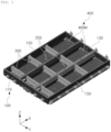
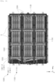
- FIG. 1 is a perspective diagram illustrating a battery case according to an embodiment of the present invention.
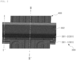
- FIG. 2 is a diagram illustrating a width-direction member 300 in which a plurality of width-direction units are coupled to each other in a height direction, and a cooling panel 400.
- a battery case according to an embodiment of the present invention may include a side frame 100, a longitudinal member 200, a width-direction member 300, and a cooling panel 400.
- the side frame 100 may be installed to surround a side surface.
- the internal portion of the side frame 100 may have a hollow quadrangular shape on a plane, and the width-direction member 300, the longitudinal member 200, and the cooling panel 400 may be disposed in the side frame 100.
- the longitudinal member 200 may extend in the length direction in the side frame 100 and may be installed throughout the internal portion of the side frame 100.
- the longitudinal member 200 may extend in the length direction, and a plurality of longitudinal members 200 may be spaced apart from each other in the width direction.
- the longitudinal member 200 may be installed in the side frame 100 and may extend in the length direction such that both ends may be connected to the side frame 100.
- the longitudinal member 200 may support the front frame 110 and the rear frame 130 opposing the side frame 100.
- two longitudinal members 200 may be spaced apart from each other in the width direction.
- the width-direction member 300 may extend in the width direction in the side frame 100 and may be connected to intersect with the longitudinal member 200, and may include a first lower width-direction unit 301-1 and a second lower width-direction disposed overlapping in the height direction.
- the width-direction member 300 may be installed in the side frame 100, may extend in the width direction, and a plurality of width-direction members 300 may be installed spaced apart from each other in the length direction.
- a plurality of width-direction units may be coupled to each other in the height direction, and the cooling panel 400 may be installed by penetrating a region between adjacent width-direction units coupled to each other in the height direction.
- Each of the width-direction units may have components such as a second upper plate 310, a second side plate 330, and a second lower plate 350.
- the first lower width-direction unit 301-1, the second lower width-direction unit 301-2, and the upper width-direction unit 302, which will be described later, may have components such as the second upper plate 310, the second side plate 330, and the second lower plate 350, respectively.
- the cooling panel 400 may be installed through adjacent width-direction units coupled to each other in the height direction and may cool a battery module C.
- the width-direction member 300 may connect adjacent longitudinal members 200 to each other or may connect the longitudinal member 200 to the side frame 100.
- the width-direction member 300 may support the adj acent longitudinal members 200, or may support the longitudinal member 200 and the side-surface frame 150 of the side frame 100.
- FIG. 3 is a cross-sectional diagram in the direction I-I' in FIG. 2 .
- FIG. 4 is a cross-sectional diagram in the direction II-II' in FIG. 2 .
- FIG. 5 is a diagram illustrating a state in which a cooling panel is installed on an upper side of a first lower width-direction unit.
- the width-direction member 300 may include a first lower width-direction unit 301-1 and a second lower width-direction unit 301-2.
- the first lower width-direction unit 301-1 may include a form bead 370 disposed on a lower side of cooling panel 400 and penetrated by the cooling panel 400.
- the lower side of the first lower width-direction unit 301-1 may be coupled to the bottom plate 600, and the cooling panel 400 may be disposed on the form bead 370 formed on an upper side.
- the first lower width-direction unit 301-1 may include a second upper plate 310, a pair of second side plates 330, and a pair of second lower plates 350.
- the second lower plate 350 may be coupled to the bottom plate 600 by welding.
- the second upper plate 310, a pair of second side plates 330, and a pair of second lower plates 350 may form a hat-shaped cross-section.
- the second lower width-direction unit 301-2 may be disposed on an upper side of the cooling panel 400 and may be coupled to the first lower width-direction unit 301-1.
- the second lower width-direction unit 301-2 and the first lower width-direction unit 301-1 may be coupled to each other by a method such as coupling by bolts.
- the second lower width-direction unit 301-2 may be disposed on an upper side of the first lower width-direction unit 301-1 with the cooling panel 400 interposed therebetween, and the first lower width-direction unit 301-1, the cooling panel 400, and the second lower width-direction unit 301-2 may be connected to each other by bolts.
- the second lower width-direction unit 301-2 may include a second upper plate 310, a pair of second side plates 330, and a pair of second lower plates 350.
- the second lower plate 350 may be coupled to the second upper plate 310 of the first lower width-direction unit 301-1 by a method such as coupling by bolts.
- the second upper plate 310, a pair of second side plates 330, and a pair of second lower plates 350 may form a hat-shaped cross-section.
- the first lower width-direction unit 301-1 may have a hat-shaped cross-section with an open lower portion, the lower side may be coupled to the bottom plate 600 and may form a closed cross-section with the bottom plate 600, and the first lower width-direction unit 301-1 may have a form bead 370 through which the cooling panel 400 penetrates on an upper side.
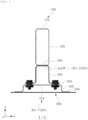
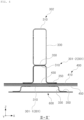
- FIG. 6 is a diagram illustrating details of a portion in which a width-direction member is coupled to a longitudinal member.
- the width-direction member 300 may further include an upper width-direction unit 302.
- the upper width-direction unit 302 may be coupled to the upper side of the second lower width-direction unit 301-2 and may be coupled to the longitudinal member 200 by a connection bracket B.
- the upper width-direction unit 302 may be coupled to an upper side of the second lower width-direction unit 301-2, and although not illustrated, depending on the size of the battery case, the plurality of upper width-direction unit 302 may be stacked on and coupled to an upper side of the second lower width-direction unit 301-2 in the height direction.
- the upper width-direction unit 302 may include a second upper plate 310, a pair of second side plates 330, and a pair of second lower plates 350.
- the second upper plate 310, a pair of the second side plates 330, and a pair of the second lower plates 350 may form a cross-section having a quadrangular shape.
- the second lower plate 350 may be coupled to the second upper plate 310 of the second lower width-direction unit 301-2 by a method such as coupling by welding.
- FIG. 7 is a diagram illustrating an embodiment in which a cross-section reinforcing member of a battery case in the present invention is installed.
- FIG. 8 is a diagram illustrating another embodiment in which a cross-section reinforcing member of a battery case in the present invention is installed.
- the longitudinal member 200 may include a lower longitudinal unit 201 and an upper longitudinal unit 202.
- the upper longitudinal unit may be coupled to an upper side of the lower longitudinal unit 201 and may form a closed cross-section together.
- the lower longitudinal unit 201 may have a hat-shaped cross-section having an open lower portion, and the lower side may be coupled to the bottom plate 600 and may form a closed cross-section with the bottom plate 600.
- the upper longitudinal unit 202 may include a 'C shaped' member having an open lower portion, and the open portion may be inserted into and coupled to an upper side of the lower longitudinal unit 201.
- a recessed step 270 into which the lower portion of the upper longitudinal unit 202 is inserted may be formed on an upper side of the lower longitudinal unit 201.
- a lower end portion of the upper longitudinal unit 202 may be mounted on the recessed step 270 of the lower longitudinal unit 201, and the upper longitudinal unit 202 and the lower longitudinal unit 201 may be coupled to each other by welding.
- Each of the longitudinal units may have components such as a first upper plate 210, a first side plate 230, and a first lower plate 250.
- the upper longitudinal unit 202 and the lower longitudinal unit 201 which will be described later, may have components such as the first upper plate 210, the first side plate 230, and the first lower plate 250, respectively.
- the battery case may further include cross-section reinforcing member 500.
- the cross-section reinforcing member 500 may be installed in the longitudinal member 200, may be disposed at a connection point at which the width-direction member 300 is connected, and may support the width-direction internal surface of the longitudinal member 200.
- the cross-section reinforcing member 500 may be configured to support two width-direction internal surfaces of the longitudinal member 200.
- the longitudinal member 200 may extend in the length direction, and a hollow portion may be formed therein.
- the longitudinal member 200 may have a hollow portion, which may be advantageous for reducing weight, but buckling may occur due to an impact load in the width direction, and the cross-section reinforcing member 500 may reinforce the component.
- the cross-section reinforcing member 500 may be installed in the longitudinal member 200 disposed between adjacent width-direction members 300, spaced apart from each other in the width direction, and may include a reinforcing bulkhead 501 supporting the adjacent width-direction member 300.
- the reinforcing bulkhead 501 may assure continuity of the cross-section in the width direction between two width-direction members 300 spaced apart from each other in the width direction.
- the longitudinal member 200 including the reinforcing bulkhead 501 installed therein may be disposed between two width-direction members 300 spaced apart from each other in the width direction.
- the reinforcing bulkhead 501 and the width-direction member 300 may be disposed with the first side plate 230 of the longitudinal member 200 interposed therebetween.
- the reinforcing bulkhead 501 may be coupled to an internal surface of the first side plate 230 of the longitudinal member 200, and the width-direction member 300 may be coupled to the internal surface of the first side plate 230 of the longitudinal member 200 corresponding to a position to which the reinforcing bulkhead 501 is coupled.
- the reinforcing bulkhead 501 may be coupled to the internal surface of the first side plate 230 of the longitudinal member 200 by welding.
- the width-direction member 300 on the left, the first side plate 230 on the left, the reinforcing bulkhead 501, the first side plate 230 on the right, and the width-direction member 300 on the right may be disposed in the width direction.
- the reinforcing bulkhead 501 may be coupled to the internal surface of the first side plate 230 of the upper longitudinal unit 202 of the longitudinal member 200, and the upper width-direction unit 302 of the width-direction member 300 may be coupled to the internal surface of the first side plate 230 of the upper longitudinal unit 202 corresponding to a position to which the reinforcing bulkhead 501 is coupled.
- the reinforcing bulkhead 501 may be coupled to the internal surface of the first side plate 230 of the lower longitudinal unit 201 of the longitudinal member 200, and the second lower width-direction unit 301 of the width-direction member 300 -2 may be coupled to the internal surface of the first side plate 230 of the lower longitudinal unit 201 corresponding to a position to which the reinforcing bulkhead 501 is coupled.
- the reinforcing bulkhead 501 and the width-direction member 300 may have cross-sections having corresponding shapes.
- the reinforcing bulkhead 501 and the width-direction member 300 may be disposed in corresponding positions with the first side plate 230 of the longitudinal member 200 interposed therebetween.
- the reinforcing bulkhead 501 may have a ' ⁇ shaped' cross-section corresponding thereto.
- the reinforcing bulkhead 501 may have a ' ⁇ shaped' cross-section corresponding thereto.
- the ' ⁇ shaped' cross-sectional portion of the width-direction member 300 and the ' ⁇ shaped' cross-sectional portion of the reinforcing bulkhead 501 may be disposed in corresponding positions with the first side plate 230 of the longitudinal member 200 therebetween. Accordingly, continuity of the cross-section may be maintained by the width-direction member 300 on the left, the first side plate 230 on the left, the reinforcing bulkhead 501, the first side plate 230 on the right, and the width-direction member 300 on the right, thereby resisting against impact load in the width direction.
- the reinforcing bulkhead 501 and the width-direction member 300 may have a cross-section of a shape in which at least portions of the cross-section correspond to each other.
- the reinforcing bulkhead 501 may have a ' ⁇ shaped' cross-section corresponding to the ' ⁇ shaped' cross-section of the width-direction member 300.
- the ' ⁇ shaped' cross-section of the width-direction member 300 and the ' ⁇ shaped' cross-section of the reinforcing bulkhead 501 may be disposed in corresponding positions with the first side plate 230 of the longitudinal member 200 interposed therebetween.
- FIG. 9 is a diagram illustrating another embodiment in which a cross-section reinforcing member 500 of a battery case in the present invention is installed.
- the width-direction member 300 may be coupled to the longitudinal member 200 by a connection bracket B.
- the cross-section reinforcing member 500 may be installed in the longitudinal member 200 disposed between adjacent connection brackets B, spaced apart from each other in the width direction, and may include a tubular reinforcing sleeve 502 supporting the adjacent connection bracket B.
- the reinforcing sleeve 502 may assure continuity of the cross-section in the width direction between two connection brackets B connected to the width-direction member 300.
- the longitudinal member 200 including the reinforcing sleeve 502 installed therein may be disposed between two connection brackets B spaced apart from each other in the width direction.
- the reinforcing sleeve 502 may support two width-direction internal surfaces of the longitudinal member 200. Also, the two connection brackets B and the longitudinal member 200 may be fastened by a reinforcing bolt member 503. Specifically, the reinforcing bolt member 503 may be fastened by penetrating the connection bracket B on the left, the longitudinal member 200, the reinforcing sleeve 502 and the connection bracket B on the right.
- the first bracket B1 of the connection bracket B may be coupled to the width-direction member 300 by bolt-fastening or welding, and the second bracket B2 of connection bracket B may be coupled to the reinforcing bolt member 503 together with the longitudinal member 200 and the reinforcing sleeve 502.
- FIG. 10 is a diagram illustrating a cooling plate D of a battery case of a comparative example as compared to a battery case in the present invention.
- FIG. 11 is a diagram illustrating a cooling panel 400 of a battery case according to an embodiment of the present invention as compared to the comparative example in FIG. 10 .
- FIG. 12 is a diagram illustrating a state in which an upper width-direction unit 302 is additionally installed in FIG. 11 .
- FIG. 13 is a diagram illustrating a state in which a battery module C is installed between a longitudinal member 200 and a width-direction member 300 in FIG. 12 .
- unit cooling panels 400M may be disposed in a unit space formed between adjacent longitudinal members 200 spaced apart from each other in the width direction or formed between the longitudinal unit and the side frame 100 spaced apart from each other in the width direction.
- the unit space may be formed between two longitudinal members 200 spaced apart from each other in the width direction or between the longitudinal unit and the side frame 100 spaced apart from each other in the width direction.
- the front frame 110 of the side frame 100 may be disposed on a front side of the unit space, and the front frame 110 of the side frame 100 may be disposed on a rear side.
- Two longitudinal units may be spaced apart from each other in the width direction on a side surface of the unit space, or a longitudinal unit may be disposed on one side surface of a unit space, and a side-surface frame 150 may be disposed on the other side surface of the unit space and may be spaced apart from the longitudinal unit and in the width direction.
- the unit space may be surrounded by the front frame 110, a pair of longitudinal units, and the rear frame 130, or may be surrounded by the front frame 110, a longitudinal unit, the side-surface frame 150, and the rear frame 130.
- the unit cooling panel 400M may be installed in the length direction across an internal portion of the side frame 100.
- the unit cooling panel 400M may be disposed on a lower side of the battery module C and may cool the battery module C.
- the unit cooling panel 400M may receive cold air by connecting to the cooling line 450.
- the unit cooling panel 400M may be installed individually in the unit space.
- two longitudinal members 200 may be spaced apart from each other in the width direction, and three unit spaces may be spaced apart from each other in the width direction.
- Three unit cooling panels 400M may be installed in three unit spaces.
- the unit cooling panels 400M formed integrally may be installed in the unit space.
- the cooling panel 400 may include three unit cooling panels 400M, and the three unit cooling panels 400M may be spaced apart from each other in the width direction.
- the unit cooling panel 400M When a single unit cooling panel 400M is disposed between two longitudinal members 200 spaced apart from each other in the width direction, and a single unit cooling panel 400M is disposed between the side frame 100 on the left side in the width direction and the longitudinal member 200, the unit cooling panel 400M may be disposed between the longitudinal unit and the side frame 100 on the right side of the width direction, and three unit cooling panels 400M may be installed.
- unit cooling panels 400M are illustrated and described to be installed, but an embodiment thereof is not limited thereto, and two or four or more unit cooling panels 400M may be formed.
- the cooling panel 400 When the cooling panel 400 is installed throughout the battery case and the cooling water flows throughout the entire battery case, there is a problem in that the cooling flow path may be lengthened, such that a cooling temperature loss may increase, and cooling performance may deteriorate.
- the cooling panel 400 may improve cooling performance by preventing the cooling flow path from being excessively lengthened by installing the unit cooling panel 400M individually in the unit space, and may reduce the size of the unit cooling panel 400M such that there may be the effect of allowing molding and assembly of the unit cooling panel 400M to be easily performed by reducing the spring-back phenomenon of the unit cooling panel 400M occurring when molding the unit cooling panel 400M.
- the unit cooling panel 400M may include a single member installed throughout the plurality of width-direction members 300 spaced apart from each other in the length direction in the side frame 100.
- FIG. 10 is a diagram illustrating a cooling plate D of a battery case of a comparative example as compared to a battery case in the present invention.
- FIG. 11 is a diagram illustrating a cooling panel 400 of a battery case according to an embodiment of the present invention as compared to the comparative example in FIG. 10 .
- a divided cooling plate D may need to be installed, and an additional tube structure E may be necessary to connect a flow path of the cooling plate D in each zone.
- a space for the flow path to pass through may need to be assured in the upper end portion of the width-direction member 300 or the flow path may need to be assured by drilling a hole in the width-direction member 300, which may be problematic.
- the comparative example has structural problems in terms of increasing battery capacity in a limited space and protecting from external impact.
- the unit cooling panel 400M may be configured as a single unit installed across a plurality of width-direction members 300 spaced apart from each other in the length direction in the side frame 100, differently from the comparative example, it may not be necessary to install a plurality of cooling plates D divided in the unit space, and no additional tube structure may be necessary to connect the flow path of cooling plate D in each zone, such that there may be the effect of maximizing battery capacity and stably protecting from external impact.
- the unit cooling panel 400M may include a cooling module plate 410 and a connection module plate 430.
- a plurality of cooling module plates 410 may be installed and spaced apart from each other in the length direction and may cool the battery module C.
- connection module plate 430 may connect two cooling module plates 410 to each other.
- the cooling module plate 410 and the connection module plate 430 may be manufactured integrally as a single metal plate such as steel material.
- the battery module C may be disposed between two adjacent width-direction members 300 spaced apart from each other in the length direction.
- the cooling module plate 410 may be disposed between two adjacent width-direction members 300 spaced apart from each other in the length direction and may cool the battery module C, and the connection module plate 430 may be installed with a smaller width than the cooling module plate 410 and may be disposed throughout in a region between the first lower width-direction unit 301-1 of the width-direction member 300 and the second lower width-direction unit 301-2 of the width-direction member 300.
- connection module plate 430 may be installed with a smaller width than the cooling module plate 410, thereby reducing transfer of cold air to the width-direction member 300 while connecting two cooling module plates 410.
- connection module plate 430 is installed with a smaller width than the cooling module plate 410
- the connection module plate 430 may be installed between the first lower width-direction unit 301-1 and the second lower width-direction unit 301-2, in which the connection module plate 430 is coupled in the height direction, such that rigidity may be reinforced by the first lower width-direction unit 301-1 and the second lower width-direction unit 301-2, and problems such as damage to the connection module plate 430 may not occur.
- connection module plate 430 may be disposed to fit perfectly between the first lower width-direction unit 301-1 and the second lower width-direction unit 301-2.
- the partial region of the connection module plate 430 may be installed throughout a region between the first lower width-direction unit 301-1 and the second lower width-direction unit 301-2, and the other partial region of the connection module plate 430 may be disposed externally of the first lower width-direction unit 301-1 and the second lower width-direction unit 301-2.
- the cooling panel 400 may be installed across four width-direction members 300 spaced apart from each other in the length direction.
- the cooling panel 400 may have a shape in which three cooling module plates 410 are connected to each other, and the cooling module plate 410 may be disposed between two adjacent width-direction members 300.
- the cooling panel 400 may not be divided by the width-direction member 300.
- FIG. 14 is a perspective diagram illustrating a battery case according to another embodiment of the present invention.
- FIG. 15 is a plan diagram illustrating a small-sized battery case 1 and a large-sized battery case 2.
- FIG. 16 is a cross-sectional diagram illustrating a longitudinal member 1200 including an upper longitudinal unit 1202 in which a plurality of first variable units 1202U are replaced.
- FIG. 17 is a diagram illustrating an example to which FIG. 3 is applied.
- the size of the battery case in the length direction (X-axis), the width direction (Y-axis), and the height direction (Z-axis) may change. Accordingly, the size of the components included in the battery case in the present invention, such as the longitudinal member 1200 and the width-direction member 1300, may also change.
- the length direction extension length in the case of changing the size of the battery case in the length direction and the width direction, the length direction extension length, it may be easily responded to by changing the extension length of the longitudinal member 1200 in the length direction, the extension length of the width-direction member 1300 in the width direction without changing cross-sectional shapes of the longitudinal member 1200 and the width-direction member 1300.
- the longitudinal member 1200 and the width-direction member 1300 are not configured as a single component, and a plurality of the components may be designed to be distinct from each other in the height direction and may be coupled to each other in the height direction, such that it may easily respond to changes in the size of the battery case in the height direction.
- the battery case according to an embodiment of the present invention may include a side frame 1100, a longitudinal member 1200, and a width-direction member 1300.
- the side frame 1100 may be installed to surround a side surface.
- an internal portion of the side frame 1100 may have a hollow quadrangular shape on a plane, and the width-direction member 1300, the longitudinal member 1200, and the cooling panel 1400 may be disposed in the side frame 1100.
- the longitudinal member 1200 may extend in the length direction in the side frame 1100 and may be installed across the internal portion of the side frame 1100.
- the longitudinal member 1200 may extend in the length direction, and a plurality of the longitudinal members 1200 may be spaced apart from each other in the width direction.
- the longitudinal member 1200 may be installed in the side frame 1100 and may extend in the length direction such that both ends may be connected to the side frame 1100.
- the longitudinal member 1200 may support the front frame 1110 and rear frame 1130 opposing the side frame 1100.
- two longitudinal members 1200 may be spaced apart from each other in the width direction.
- the longitudinal member 1200 may have components such as a first upper plate 1210, a first side plate 1230, and a first lower plate 1250.
- the upper longitudinal unit 1202 and the lower longitudinal unit 1201, which will be described later, may have components such as the first upper plate 1210, the first side plate 1230, and the first lower plate 1250, respectively.
- the width-direction member 1300 may extend in the width direction in the side frame 1100 and may be connected to intersect with the longitudinal member 1200.
- the width-direction member 1300 may be installed in the side frame 1100, may extend in the width direction, and a plurality of the width-direction member 1300 may be installed and spaced apart from each other in the length direction.
- a plurality of width-direction units may be coupled to each other in the height direction, and the cooling panel 1400 may be installed by penetrating a region between adjacent width-direction units coupled to each other in the height direction.
- the width-direction unit may have components such as a second upper plate 1310, a second side plate 1330, and a second lower plate 1350.
- a first lower width-direction unit 1301-1, a second lower width-direction unit 1301-2, and an upper width-direction unit 1302 may include the second upper plate 1310, the second side plate 1330, and the second lower plate 1350, respectively, which will be described later.
- the longitudinal member 1200 may include a lower longitudinal unit 1201 and an upper longitudinal unit 1202.
- the lower longitudinal unit 1201 may be disposed on the lower side.
- the upper longitudinal unit 1202 may include a plurality of first variable units 1202U having different heights, and at least one of the plurality of first variable units 1202U may be coupled to an upper side of the lower longitudinal unit 1201.
- the height of the longitudinal member 1200 of the upper longitudinal unit 1202 may be determined depending on a height of the first variable unit 1202U selectively coupled.
- a 1-1 variable unit 1202U-1 having a high height may be installed on an upper side of the lower longitudinal unit 1201
- a 1-2 variable unit 1202U-2 having a low height may be installed on the upper side of the lower longitudinal unit 1201.
- the same components may be applied to the lower longitudinal unit 1201 of the longitudinal member 1200, and the first variable unit 1202U having a different height may be applied to the upper longitudinal unit 1202.
- the basic structure of the battery case may be maintained, and production efficiency may be improved by reducing component changes, and the size of the battery case may be freely changed.
- the lower longitudinal unit 1201 may be maintained and the height of the first variable unit 1202U coupled to the upper portion of the lower longitudinal unit 1201 may be selected, such that there may be the effect of easily responding to changes in the size of the battery case in the height direction.
- the width-direction member 1300 may connect the adjacent longitudinal member 1200 or may connect the longitudinal member 1200 to the side frame 1100.
- the width-direction member 1300 may support the adjacent longitudinal member 1200, or may support the side frame 1150 of the longitudinal member 1200 and the side frame 1100.
- FIG. 18 is a cross-sectional diagram illustrating a width-direction member including an upper width-direction unit 1302 in which a plurality of second variable units 1302U are replaced.
- FIG. 19 is a diagram illustrating an example to which FIG. 18 is applied.
- a width-direction member 1300 may include a lower width-direction unit 1301 and an upper width-direction unit 1302.
- the lower width-direction unit 1301 may be disposed on a lower side.
- the upper width-direction unit 1302 may include a plurality of second variable units 1302U having different heights, and at least one of the plurality of second variable units 1302U may be coupled to an upper side of the lower width-direction unit 1301.
- the upper width-direction unit 1302 may determine a height of the width-direction member 1300 depending on a height of the second variable unit 1302U selectively coupled.
- a 2-1 variable unit 1302U-1 having a great height may be installed on the upper side of the lower width-direction unit 1301, and in a small-sized battery case 11, the 2-2 variable unit 1302U-2 having a low height may be installed on the upper side of lower width-direction unit 1301.
- the same components may be applied to the lower width-direction unit 1301 of the longitudinal member 1200, and the second variable unit 1302U having a different height may be applied to the upper width-direction unit 1302.
- the lower width-direction unit 1301 may be maintained, and the height of the second variable unit 1302U, which is coupled to the upper portion of the lower width-direction unit 1301, may be selected, such that there may be the effect of easily responding to changes in the size of the battery case in the height direction.
- the heights of the lower longitudinal unit 1201 and the lower width-direction unit 1301, which are commonly used in the small-sized battery case 11 and the large-sized battery case 12, may be configured to correspond to each other.
- the lower longitudinal unit 1201 and the lower width-direction unit 1301 may have the same height, and in this case, there may be an effect of efficiently responding to collision loads of the battery case.
- FIG. 20 is a diagram illustrating an embodiment in which a cross-section reinforcing member 1500 of a battery case in the present invention is installed.
- FIG. 21 is a diagram illustrating another embodiment in which a cross-section reinforcing member 1500 of a battery case in the present invention is installed.
- the battery case may further include a cross-section reinforcing member 1500.
- the cross-section reinforcing member 1500 may be installed in a longitudinal member 1200, may be disposed at a connection point at which the width-direction member 1300 is connected, and may support a width-direction internal surface of the longitudinal member 1200.
- the cross-section reinforcing member 1500 may support two width-direction internal surfaces of the longitudinal member 1200.
- the longitudinal member 1200 may extend in the length direction, and a hollow portion may be formed therein.
- the longitudinal member 1200 may have a hollow portion, which may be advantageous for reducing a weight, but buckling may occur due to impact load in the width direction, and the cross-section reinforcing member 1500 may reinforce the component.
- the upper longitudinal unit 1202 may form a closed cross-section in which the first variable unit 1202U selected from among the plurality of first variable units 1202U is coupled to the upper side of the lower longitudinal unit 1201.
- the upper longitudinal unit 1202 may include a ' ⁇ shaped' member having an open lower portion, and the open portion may be coupled to an upper side of the lower longitudinal unit 1201.
- a recessed step 1270 into which the lower portion of the upper longitudinal unit 1202 is inserted may be formed on the upper side of the lower longitudinal unit 1201.
- the lower end portion of the upper longitudinal unit 1202 may be mounted on the recessed step 1270 of the lower longitudinal unit 1201, and the upper longitudinal unit 1202 and the lower longitudinal unit 1201 may be coupled to each other by welding.
- the lower longitudinal unit 1201 may have a hat-shaped cross-section having an open lower portion, and the lower side may be coupled to the bottom plate 1600 and may form a closed cross-section with the bottom plate 1600.
- the cross-section reinforcing member 1500 may be installed in the longitudinal member 1200 disposed between adjacent width-direction members 1300, spaced apart from each other in the width direction, and may include a reinforcing bulkhead 1501 supporting adjacent width-direction members 1300.
- the reinforcing bulkhead 1501 may assure continuity of the cross-section in the width direction between two width-direction members 1300 spaced apart from each other in the width direction.
- the longitudinal member 1200 installed in the reinforcing bulkhead 1501 may be disposed between two width-direction members 1300 spaced apart from each other in the width direction.
- the reinforcing bulkhead 1501 and the width-direction member 1300 may be disposed with the first side plate 1230 of the longitudinal member 1200 interposed therebetween.
- the reinforcing bulkhead 1501 may be coupled to an internal surface of the first side plate 1230 of the longitudinal member 1200, and the width-direction member 1300 may be coupled to an internal surface of the first side plate 1230 of the longitudinal member 1200 corresponding to a position to which the reinforcing bulkhead 1501 is coupled.
- the reinforcing bulkhead 1501 may be coupled to the internal surface of the first side plate 1230 of the longitudinal member 1200 by welding.
- the width-direction member 1300 on the left, the first side plate 1230 on the left, the reinforcing bulkhead 1501, the first side plate 1230 on the right, and the width-direction member 1300 on the right may be disposed in the width direction.
- the reinforcing bulkhead 1501 may be coupled to an internal surface of the first side plate 1230 of the upper longitudinal unit 1202 of the longitudinal member 1200, and the upper width-direction unit 1302 of the width-direction member 1300 may be coupled to an internal surface of the first side plate 1230 of the upper longitudinal unit 1202 corresponding to a position to which the reinforcing bulkhead 1501 is coupled.
- the reinforcing bulkhead 1501 may be coupled to the internal surface of the first side plate 1230 of the lower longitudinal unit 1201 of the longitudinal member 1200, and the second lower width-direction unit 1301-2 of the width-direction member 1300 may be coupled to the internal surface of the first side plate 1230 of the lower longitudinal unit 1201 corresponding to a position to which the reinforcing bulkhead 1501 is coupled.
- the reinforcing bulkhead 1501 and the width-direction member 1300 may have cross-sections having corresponding shapes.
- the reinforcing bulkhead 1501 and the width-direction member 1300 may be disposed in corresponding positions with the first side plate 1230 of the longitudinal member 1200 interposed therebetween.
- the reinforcing bulkhead 1501 may have a corresponding ' ⁇ shaped' cross-section.
- the reinforcing bulkhead 1501 may have a corresponding ' ⁇ shaped' cross-section.
- the ' ⁇ shaped' cross-sectional portion of the of the width-direction member 1300 and the ' ⁇ shaped' of cross-sectional portion of the reinforcing bulkhead 1501 may be disposed in corresponding positions with the first side plate 1230 of the longitudinal member 1200 interposed therebetween. Accordingly, continuity of the cross-section may be maintained with the width-direction member 1300 on the left, the first side plate 1230 on the left, the reinforcing bulkhead 1501, the first side plate 1230 on the right, and the width-direction member 1300 on the right, thereby stably resisting against impact load in the width direction.
- the reinforcing bulkhead 1501 and the width-direction member 1300 may have cross-sections having a shape in which at least portions of the cross-section correspond to each other.
- the reinforcing bulkhead 1501 may have a ' ⁇ shaped' cross-section corresponding to the ' ⁇ shaped' cross-section of the width-direction member 1300.
- the ' ⁇ shaped' cross-section of the width-direction member 1300 and the ' ⁇ shaped' cross-section of the reinforcing bulkhead 1501 may be disposed in corresponding positions with the first side plate 1230 of the longitudinal member 1200 interposed therebetween.
- FIG. 22 is a diagram illustrating another embodiment in which a cross-section reinforcing member 1500 of a battery case in the present invention is installed.
- the width-direction member 1300 may be coupled to the longitudinal member 1200 through a connection bracket B.
- the cross-section reinforcing member 1500 may be installed in the longitudinal member 1200 disposed between adjacent connection brackets B spaced apart from each other in the width direction, and may include a tubular reinforcing sleeve 1502 supporting the adjacent connection bracket B.
- the reinforcing sleeve 1502 may assure continuity of the cross-section in the width direction between the two connection brackets B connected to the width-direction member 1300.
- the longitudinal member 1200 including the reinforcing sleeve 1502 installed therein may be disposed between two connection brackets B spaced apart from each other in the width direction.
- the reinforcing sleeve 1502 may support two width-direction internal surfaces of the longitudinal member 1200. Also, the two connection brackets B and the longitudinal member 1200 may be fastened by a reinforcing bolt member 1503. Specifically, the reinforcing bolt member 1503 may be fastened by penetrating the connection bracket B on the left, the longitudinal member 1200, the reinforcing sleeve 1502 and the connection bracket B on the right.
- the first bracket B1 of the connection bracket B may be coupled to the width-direction member 1300 by bolt-fastening or welding, and the second bracket B2 of the connection bracket B may be coupled to the bolt reinforcing member 1503 together with the longitudinal member 1200 and the reinforcing sleeve 1502.
- the battery case may further include a cooling panel 1400.
- the width-direction member 1300 may have a plurality of width-direction units coupled to each other the height direction.
- the cooling panel 1400 may cool a battery module C by being installed through adjacent width-direction units coupled to each other in the height direction.
- FIG. 23 is a diagram illustrating a width-direction member 1300 and a cooling panel 1400 in which a plurality of width-direction units are coupled to each other in a height direction.
- FIG. 24 is a cross-sectional diagram in the direction I-I' in FIG. 23 .
- FIG. 25 is a cross-sectional diagram in the direction II-II' in FIG. 23 .
- FIG. 26 is a diagram illustrating a state in which a cooling panel 1400 is installed on an upper side of a first lower width-direction unit 1301-1.
- the width-direction member 1300 may include a first lower width-direction unit 1301-1 and a second lower width-direction unit 1301-2.
- the first lower width-direction unit 1301-1 may be disposed on a lower side of the cooling panel 1400 and may have a form bead 1370 through which the cooling panel 1400 and the cooling line 1450 cooling the cooling panel 1400 penetrates.
- a lower side of the first lower width-direction unit 1301-1 may be coupled to the bottom plate 1600, and the cooling panel 1400 and the cooling line 1450 cooling the cooling panel 1400 may be disposed on the form bead 1370 formed on an upper side.
- the first lower width-direction unit 1301-1 may include a second upper plate 1310, a pair of second side plates 1330, and a pair of second lower plates 1350.
- the second lower plate 1350 may be coupled to the bottom plate 1600 by welding.
- the second upper plate 1310, a pair of second side plates 1330, and a pair of second lower plates 1350 may form a hat-shaped cross-section.
- the second lower width-direction unit 1301-2 may be disposed on an upper side of the cooling panel 1400 and may be coupled to the first lower width-direction unit 1301-1.
- the second lower width-direction unit 1301-2 and the first lower width-direction unit 1301-1 may be coupled to each other by a method such as coupling by bolts.
- the second lower width-direction unit 1301-2 may be disposed on an upper side of the first lower width-direction unit 1301-1 with the cooling panel 1400 interposed therebetween, and the first lower width-direction unit 1301-1, the cooling panel 1400, and the second lower width-direction unit 1301-2 may be connected to each other by bolts.
- the second lower width-direction unit 1301-2 may include a second upper plate 1310, a pair of second side plates 1330, and a pair of second lower plates 1350.
- the second lower plate 1350 may be coupled to the second upper plate 1310 of the first lower width-direction unit 1301-1 by a method such as coupling by bolts.
- the second upper plate 1310, a pair of second side plates 1330, and a pair of second lower plates 1350 may form a hat-shaped cross-section.
- the first lower width-direction unit 1301-1 may have a hat-shaped cross-section having an open lower portion, the lower side may be coupled to the bottom plate 1600 and may form a closed cross-section with the bottom plate 1600, and the first lower width-direction unit 1301-1 may have a cooling panel 1400 on the upper side and a form bead 1370 through which the cooling line 1450 cooling the cooling panel 1400 penetrates.
- FIG. 27 is a diagram illustrating details of a portion in which a width-direction member 1300 is coupled to a longitudinal member 1200.
- the width-direction member 1300 may further include an upper width-direction unit 1302.
- the upper width-direction unit 1302 may be coupled to an upper side of the second lower width-direction unit 1301-2 and may include a plurality of second variable units 1302U having different heights, and at least one of the plurality of second variable units 1302U may be coupled to the upper side of the lower width-direction unit 1301, and the upper width-direction unit 1302 may be coupled to the longitudinal member 1200 by a connection bracket B.
- FIG. 28 is a diagram illustrating a cooling plate D of a battery case of a comparative example as compared to a battery case in the present invention.
- FIG. 29 is a diagram illustrating a cooling panel 1400 of a battery case according to an embodiment of the present invention as compared to the comparative example in FIG. 28 .
- FIG. 30 is a diagram illustrating a state in which an upper width-direction unit 1302 is additionally installed in FIG. 29 .
- FIG. 31 is a diagram illustrating a state in which a battery module is installed between the longitudinal member 1200 and the width-direction member 1300 in FIG. 30 .
- the unit cooling panel 1400M may be disposed in a unit space formed between adjacent longitudinal members 1200 spaced apart from each other in the width direction or between the longitudinal member 1200 and the side frame 1100 spaced apart from each other in the width direction.
- the unit space may be formed between two longitudinal members 1200 spaced apart from each other in the width direction or between the longitudinal unit and the side frame 1100 spaced apart from each other in the width direction.
- the front frame 1110 of the side frame 1100 may be disposed on a front side of the unit space, and the front frame 1110 of the side frame 1100 may be disposed on a rear side.
- two longitudinal units may be spaced apart from each other in the width direction, or a longitudinal unit may be disposed on one side surface of the unit space, and the side frame 1150 may be disposed on the other side surface of the unit space and may be spaced apart from the longitudinal unit in the width direction.
- the unit space may be surrounded by a front frame 1110, a pair of longitudinal units, and a rear frame 1130, or may be surrounded by the front frame 1110, the longitudinal unit, the side frame 1150, and the rear frame 1130.
- the unit cooling panel 1400M may be installed in the length direction across an internal portion of the side frame 1100.
- the unit cooling panel 1400M may be disposed on a lower side of battery module C and may cool a battery module C.
- the unit cooling panel 1400M may receive cold air by connecting to the cooling line 1450.
- the unit cooling panel 1400M may be installed individually in the unit space.
- two longitudinal members 1200 may be spaced apart from each other in the width direction, and three unit spaces may be spaced apart from each other in the width direction.
- Three unit cooling panels 1400M may be installed in three unit spaces. That is, the unit cooling panel 1400M integrally formed may be installed in the unit space.
- the cooling panel 1400 may include three unit cooling panels 1400M, and the three unit cooling panels 1400M may be spaced apart from each other in the width direction.
- a single unit cooling panel 1400M When a single unit cooling panel 1400M is disposed between two longitudinal members 1200 spaced apart from each other in the width direction, and a single unit cooling panel 1400M is disposed between the side frame 1100 on the left side of the width direction and the longitudinal member 1200, a single unit cooling panel 1400M may be disposed between the longitudinal unit and the side frame 1100 on the right side in the width direction, and three unit cooling panels 1400M may be installed.
- unit cooling panels 1400M are illustrated and described to be installed, but an embodiment thereof is not limited thereto, and two or four or more unit cooling panels 1400M may be formed.
- the cooling flow path may be lengthened, a cooling temperature loss may increase, and cooling performance may deteriorate, which may be problematic.
- the unit cooling panel 1400M may be installed individually in each unit space, such that cooling performance may be improved by preventing the cooling flow path from being excessively lengthened, and by reducing the size of the unit cooling panel 1400M, the spring-back phenomenon of the unit cooling panel 1400M occurring during molding of the unit cooling panel 1400M may be reduced, such that there may be the effect of allowing molding and assembly of the unit cooling panel 1400M to be easily performed.
- the unit cooling panel 1400M may include a single member installed throughout the plurality of width-direction members 1300 spaced apart from each other in the length direction in the side frame 1100.
- a divided cooling plate D may need to be installed, and an additional tube structure E may be necessary to connect a flow path of the cooling plate D in each zone.
- a space for the flow path to pass through may need to be assured in the upper end portion of the width-direction member 1300 or the flow path may need to be assured by drilling a hole in the width-direction member 1300, which may be problematic.
- the comparative example has structural problems in terms of increasing battery capacity in a limited space and protecting from external impact.
- the unit cooling panel 400M may be configured as a single unit installed across a plurality of width-direction members 1300 spaced apart from each other in the length direction in the side frame 1100, differently from the comparative example, it may not be necessary to install a plurality of cooling plates D divided in the unit space, and no additional tube structure may be necessary to connect the flow path of the cooling plate D in each zone, such that there may be the effect of maximizing battery capacity and stably protecting from external impact.
- the unit cooling panel 1400M may include a cooling module plate 1410 and a connection module plate 1430.
- a plurality of cooling module plates 1410 may be spaced apart from each other in the length direction to cool battery module C.
- connection module plate 1430 may connect two cooling module plates 1410 to each other.
- the cooling module plate 1410 and the connection module plate 1430 may be manufactured integrally as a single metal plate such as a steel material.
- the cooling module plate 1410 may be disposed between adjacent width-direction members 1300 spaced apart from each other in the length direction and may cool battery module C, and the connection module plate 1430 may be installed with a smaller width than the cooling module plate 1410 and may be disposed between the first lower width-direction unit 1301-1 of the width-direction member 1300 and the second lower width-direction unit 1301-2 of the width-direction member 1300.
- the battery module C may be disposed between two adjacent width-direction members 1300 spaced apart from each other in the length direction.
- connection module plate 1430 is installed with a smaller width than the cooling module plate 1410, transfer of cold air to the width-direction member 1300 may be reduced while connecting two cooling module plates 1410 to each other.
- connection module plate 1430 is installed with a smaller width than the cooling module plate 1410
- the connection module plate 1430 may be installed between the first lower width-direction unit 1301-1 and the second lower width-direction unit 1301-2 coupled to each other in the height direction, such that rigidity may be reinforced by the first lower width-direction unit 1301-1 and the second lower width-direction unit 1301-2, such that problems such as damage to the connection module plate 1430 may not occur.
- connection module plate 1430 may be disposed to fit perfectly between the first lower width-direction unit 1301-1 and the second lower width-direction unit 1301-2.
- connection module plate 1430 may be installed between the first lower width-direction unit 1301-1 and the second lower width-direction unit 1301-2, and another partial region of the connection module plate 1430 may be disposed externally of the first lower width-direction unit 1301-1 and the second lower width-direction unit 1301-2.
- the cooling panel 1400 may be installed across four width-direction members 1300 spaced apart from each other in the length direction.
- the cooling panel 1400 may have a shape in which three cooling module plates 1410 are connected, and the cooling module plate 1410 may be disposed between two adjacent width-direction members 1300.
- the cooling panel 1400 may not be divided by the width-direction member 1300.
Landscapes
- Chemical & Material Sciences (AREA)
- Chemical Kinetics & Catalysis (AREA)
- Electrochemistry (AREA)
- General Chemical & Material Sciences (AREA)
- Engineering & Computer Science (AREA)
- Manufacturing & Machinery (AREA)
- Aviation & Aerospace Engineering (AREA)
- Battery Mounting, Suspending (AREA)
- Secondary Cells (AREA)
- Cooling, Air Intake And Gas Exhaust, And Fuel Tank Arrangements In Propulsion Units (AREA)
Applications Claiming Priority (2)
| Application Number | Priority Date | Filing Date | Title |
|---|---|---|---|
| KR1020210183152A KR20230094018A (ko) | 2021-12-20 | 2021-12-20 | 배터리케이스 |
| PCT/KR2022/020398 WO2023121135A1 (ko) | 2021-12-20 | 2022-12-15 | 배터리케이스 |
Publications (2)
| Publication Number | Publication Date |
|---|---|
| EP4456291A1 true EP4456291A1 (de) | 2024-10-30 |
| EP4456291A4 EP4456291A4 (de) | 2025-08-06 |
Family
ID=86903332
Family Applications (1)
| Application Number | Title | Priority Date | Filing Date |
|---|---|---|---|
| EP22911768.4A Pending EP4456291A4 (de) | 2021-12-20 | 2022-12-15 | Batteriegehäuse |
Country Status (6)
| Country | Link |
|---|---|
| US (1) | US20250030100A1 (de) |
| EP (1) | EP4456291A4 (de) |
| JP (1) | JP2024545509A (de) |
| KR (1) | KR20230094018A (de) |
| CN (1) | CN118402126A (de) |
| WO (1) | WO2023121135A1 (de) |
Family Cites Families (11)
| Publication number | Priority date | Publication date | Assignee | Title |
|---|---|---|---|---|
| JP3379134B2 (ja) * | 1993-03-10 | 2003-02-17 | 日産自動車株式会社 | 電気自動車のバッテリ保温構造 |
| KR200193173Y1 (ko) | 2000-03-14 | 2000-08-16 | 주식회사터울 | 리튬 배터리 케이스 |
| FR3062749B1 (fr) * | 2018-04-10 | 2023-04-14 | Sogefi Air & Cooling | Unite de batterie integrant des zones d'echanges thermiques |
| KR102475184B1 (ko) * | 2018-09-20 | 2022-12-07 | (주)엘엑스하우시스 | 전기자동차용 배터리 케이스 |
| DE102019102754B4 (de) * | 2019-02-05 | 2022-03-17 | Benteler Automobiltechnik Gmbh | Batterieträgeranordnung |
| JP6876745B2 (ja) * | 2019-05-16 | 2021-05-26 | 本田技研工業株式会社 | 車両用バッテリユニット |
| UA128548C2 (uk) * | 2019-12-24 | 2024-08-07 | Арселорміттал | Зміцнений несучий засіб для акумуляторної батареї та спосіб складання зміцненої акумуляторної батареї |
| CN212967928U (zh) * | 2020-09-10 | 2021-04-13 | 广州小鹏汽车制造有限公司 | 电池箱体及电动汽车 |
| CN213242719U (zh) * | 2020-10-09 | 2021-05-18 | 上海汽车集团股份有限公司 | 电池包及汽车 |
| CN214043865U (zh) * | 2020-12-03 | 2021-08-24 | 湖北亿纬动力有限公司 | 一种电池箱体 |
| CN214898571U (zh) * | 2021-01-14 | 2021-11-26 | 恒大新能源技术(深圳)有限公司 | 一种动力电池包及其冷却机构 |
-
2021
- 2021-12-20 KR KR1020210183152A patent/KR20230094018A/ko active Pending
-
2022
- 2022-12-15 EP EP22911768.4A patent/EP4456291A4/de active Pending
- 2022-12-15 JP JP2024534554A patent/JP2024545509A/ja active Pending
- 2022-12-15 WO PCT/KR2022/020398 patent/WO2023121135A1/ko not_active Ceased
- 2022-12-15 US US18/716,682 patent/US20250030100A1/en active Pending
- 2022-12-15 CN CN202280083900.XA patent/CN118402126A/zh active Pending
Also Published As
| Publication number | Publication date |
|---|---|
| US20250030100A1 (en) | 2025-01-23 |
| WO2023121135A1 (ko) | 2023-06-29 |
| CN118402126A (zh) | 2024-07-26 |
| EP4456291A4 (de) | 2025-08-06 |
| KR20230094018A (ko) | 2023-06-27 |
| JP2024545509A (ja) | 2024-12-09 |
Similar Documents
| Publication | Publication Date | Title |
|---|---|---|
| US12162341B2 (en) | Under body structure of automobile | |
| CN205010328U (zh) | 加强件、组合车辆车身结构以及皮卡车铰接立柱加强件 | |
| KR101896336B1 (ko) | 전기자동차용 사이드 실의 보강 유닛 | |
| CN109018023B (zh) | 可变车身结构 | |
| KR102703743B1 (ko) | 차량용 배터리 장착구조 | |
| US11383766B2 (en) | Vehicle body lower structure | |
| US10737729B2 (en) | Vehicle | |
| CN103085742A (zh) | 碰撞盒 | |
| US20190039446A1 (en) | Vehicle rear portion structure | |
| CN113471607A (zh) | 电池箱体、电池包及电池箱体的装配方法 | |
| US20230025443A1 (en) | Front Vehicle Body Structure | |
| US11440593B2 (en) | Vehicle body lower structure | |
| CN113300024A (zh) | 动力电池液冷装置、动力电池系统和车辆 | |
| KR20220063505A (ko) | 차량의 배터리 체결 구조 | |
| CN111688819A (zh) | 一种电动车的门槛结构 | |
| CN220465620U (zh) | 门槛梁结构和车辆 | |
| EP4456291A1 (de) | Batteriegehäuse | |
| US20250276658A1 (en) | Vehicle frame assembly, energy storage structure, and vehicle | |
| KR20230094383A (ko) | 배터리케이스 | |
| KR102725255B1 (ko) | 배터리 컨테이너 및 이를 포함하는 에너지 저장 시스템 | |
| JP7306544B2 (ja) | 車両下部構造 | |
| WO2024140004A1 (zh) | 快换支架及包含其的电动车辆 | |
| US11628890B2 (en) | Floor connection structure of vehicle under body | |
| KR20240104916A (ko) | 차량의 사이드실 어셈블리 | |
| US20240199125A1 (en) | Vehicle battery case |
Legal Events
| Date | Code | Title | Description |
|---|---|---|---|
| STAA | Information on the status of an ep patent application or granted ep patent |
Free format text: STATUS: THE INTERNATIONAL PUBLICATION HAS BEEN MADE |
|
| PUAI | Public reference made under article 153(3) epc to a published international application that has entered the european phase |
Free format text: ORIGINAL CODE: 0009012 |
|
| STAA | Information on the status of an ep patent application or granted ep patent |
Free format text: STATUS: REQUEST FOR EXAMINATION WAS MADE |
|
| 17P | Request for examination filed |
Effective date: 20240708 |
|
| AK | Designated contracting states |
Kind code of ref document: A1 Designated state(s): AL AT BE BG CH CY CZ DE DK EE ES FI FR GB GR HR HU IE IS IT LI LT LU LV MC ME MK MT NL NO PL PT RO RS SE SI SK SM TR |
|
| DAV | Request for validation of the european patent (deleted) | ||
| DAX | Request for extension of the european patent (deleted) | ||
| A4 | Supplementary search report drawn up and despatched |
Effective date: 20250709 |
|
| RIC1 | Information provided on ipc code assigned before grant |
Ipc: H01M 50/242 20210101AFI20250703BHEP Ipc: H01M 10/6554 20140101ALI20250703BHEP Ipc: H01M 10/613 20140101ALI20250703BHEP Ipc: H01M 10/6556 20140101ALI20250703BHEP Ipc: H01M 50/249 20210101ALI20250703BHEP Ipc: H01M 10/625 20140101ALI20250703BHEP |