EP4454875A1 - Procédé d'évaluation de l'état d'usure d'un composant d'une presse rotative ainsi que presse rotative - Google Patents
Procédé d'évaluation de l'état d'usure d'un composant d'une presse rotative ainsi que presse rotative Download PDFInfo
- Publication number
- EP4454875A1 EP4454875A1 EP24160963.5A EP24160963A EP4454875A1 EP 4454875 A1 EP4454875 A1 EP 4454875A1 EP 24160963 A EP24160963 A EP 24160963A EP 4454875 A1 EP4454875 A1 EP 4454875A1
- Authority
- EP
- European Patent Office
- Prior art keywords
- press
- rotary press
- cavities
- measured values
- punches
- Prior art date
- Legal status (The legal status is an assumption and is not a legal conclusion. Google has not performed a legal analysis and makes no representation as to the accuracy of the status listed.)
- Pending
Links
Images

Classifications
-
- B—PERFORMING OPERATIONS; TRANSPORTING
- B30—PRESSES
- B30B—PRESSES IN GENERAL
- B30B11/00—Presses specially adapted for forming shaped articles from material in particulate or plastic state, e.g. briquetting presses, tabletting presses
- B30B11/02—Presses specially adapted for forming shaped articles from material in particulate or plastic state, e.g. briquetting presses, tabletting presses using a ram exerting pressure on the material in a moulding space
- B30B11/08—Presses specially adapted for forming shaped articles from material in particulate or plastic state, e.g. briquetting presses, tabletting presses using a ram exerting pressure on the material in a moulding space co-operating with moulds carried by a turntable
-
- B—PERFORMING OPERATIONS; TRANSPORTING
- B30—PRESSES
- B30B—PRESSES IN GENERAL
- B30B11/00—Presses specially adapted for forming shaped articles from material in particulate or plastic state, e.g. briquetting presses, tabletting presses
- B30B11/02—Presses specially adapted for forming shaped articles from material in particulate or plastic state, e.g. briquetting presses, tabletting presses using a ram exerting pressure on the material in a moulding space
- B30B11/04—Presses specially adapted for forming shaped articles from material in particulate or plastic state, e.g. briquetting presses, tabletting presses using a ram exerting pressure on the material in a moulding space co-operating with a fixed mould
-
- G—PHYSICS
- G01—MEASURING; TESTING
- G01N—INVESTIGATING OR ANALYSING MATERIALS BY DETERMINING THEIR CHEMICAL OR PHYSICAL PROPERTIES
- G01N3/00—Investigating strength properties of solid materials by application of mechanical stress
- G01N3/56—Investigating resistance to wear or abrasion
-
- B—PERFORMING OPERATIONS; TRANSPORTING
- B30—PRESSES
- B30B—PRESSES IN GENERAL
- B30B11/00—Presses specially adapted for forming shaped articles from material in particulate or plastic state, e.g. briquetting presses, tabletting presses
- B30B11/005—Control arrangements
-
- B—PERFORMING OPERATIONS; TRANSPORTING
- B30—PRESSES
- B30B—PRESSES IN GENERAL
- B30B15/00—Details of, or accessories for, presses; Auxiliary measures in connection with pressing
-
- B—PERFORMING OPERATIONS; TRANSPORTING
- B30—PRESSES
- B30B—PRESSES IN GENERAL
- B30B15/00—Details of, or accessories for, presses; Auxiliary measures in connection with pressing
- B30B15/0094—Press load monitoring means
-
- B—PERFORMING OPERATIONS; TRANSPORTING
- B30—PRESSES
- B30B—PRESSES IN GENERAL
- B30B15/00—Details of, or accessories for, presses; Auxiliary measures in connection with pressing
- B30B15/26—Program-control arrangements
-
- B—PERFORMING OPERATIONS; TRANSPORTING
- B30—PRESSES
- B30B—PRESSES IN GENERAL
- B30B15/00—Details of, or accessories for, presses; Auxiliary measures in connection with pressing
- B30B15/32—Discharging presses
-
- G—PHYSICS
- G06—COMPUTING OR CALCULATING; COUNTING
- G06N—COMPUTING ARRANGEMENTS BASED ON SPECIFIC COMPUTATIONAL MODELS
- G06N20/00—Machine learning
-
- G—PHYSICS
- G06—COMPUTING OR CALCULATING; COUNTING
- G06N—COMPUTING ARRANGEMENTS BASED ON SPECIFIC COMPUTATIONAL MODELS
- G06N3/00—Computing arrangements based on biological models
- G06N3/02—Neural networks
- G06N3/08—Learning methods
Definitions
- the invention relates to a method for assessing the state of wear of a component of a rotary press
- the rotary press comprises a rotor that can be rotated by means of a rotary drive, wherein the rotor has an upper punch guide for upper press punches and a lower punch guide for lower press punches as well as a die plate arranged between the punch guides, wherein the press punches interact with cavities of the die plate
- the rotary press further comprises a filling device by means of which powder material to be pressed is filled into the cavities of the die plate
- the rotary press comprises a pressure device that, during operation, interacts with the upper press punches and with the lower press punches to press the powder material in the cavities of the die plate to form pressed pieces
- the rotary press has control cams that interact with punch heads of the press punches for controlling an axial movement of the press punches, wherein the control cams comprise an ejector cam that controls the lower press punches for ejecting
- the invention also relates to a rotary press comprising a rotor with an upper punch guide for upper press punches and a lower punch guide for lower press punches as well as a die plate arranged between the punch guides, wherein the press punches interact with cavities of the die plate, further comprising a filling device by means of which powder material to be pressed is filled into the cavities of the die plate, further comprising a pressure device which, during operation, interacts with the upper press punches and with the lower press punches for pressing the powder material in the cavities of the die plate to form pressed pieces, and further comprising control cams cooperating with punch heads of the press punches for controlling an axial movement of the press punches, wherein the control cams comprise an ejector cam which controls the lower press punches for ejecting compacts produced in the cavities from the cavities.
- Rotary presses usually have a large number of upper and lower press punches, each pair of which is assigned to a cavity of a die plate.
- the upper and lower press punches rotate together with the die plate, with their axial movement controlled by control cams and guided by upper and lower punch guides.
- the die plate passes through various devices on the rotary press, namely a filling device, in which powder material to be pressed is guided into the cavities of the die plate, and a pressure device, in which the upper and lower press punches are usually pressed into the cavities by upper and lower pressure rollers to press the powder material into pellets, such as tablets.
- the upper press punches are guided upwards out of the cavities and the pellets produced in the cavities are pushed onto the top of the die plate by the lower press punches.
- Ejector cams are provided for this purpose, which move the lower press punches upwards accordingly. For example, by a stripper, the pressed pieces are then stripped from the die plate into an outlet of the rotary press, from where they are fed for further processing.
- Rotary presses are operated with high rotor speeds and correspondingly high production speeds.
- various components of the rotary press wear out, in particular the control cams, and in particular the Ejector cams, which are subject to particular stress when they come into contact with the press rams.
- Contact with powder material to be pressed can also lead to wear.
- Components with increased wear can lead to a deterioration in the quality of the pressed tablets.
- ejector cams with increased wear can lead to defects not being detected during sorting and bad tablets not being sorted out.
- the state of wear of many components of the rotary press, in particular the ejector cams has been checked at specified maintenance intervals, usually manually by an operator. The disadvantage of this is that wear that occurs in the meantime, which can already lead to a deterioration in the quality of the tablets, may not be detected in time. Manual wear control is also complex and cannot be reliably reproduced.
- the invention is therefore based on the object of providing a method and a rotary press of the type mentioned at the beginning, with which the wear condition of components of the rotary press can be assessed reliably, in a timely and reproducible manner.
- the basic structure of the rotary press as it is the subject of the present invention or is used in the method according to the invention, was explained at the beginning.
- the upper and lower punch guides guide the press punches during their axial movement.
- the punch heads interact with control cams, which move the press punches in the axial direction as they rotate with the rotor, in particular towards and away from each other.
- the control cams are usually made up of several control cam elements. They can accommodate the punch heads in corresponding guide receptacles or only rest against a mirror surface of the punch heads.
- the pressure device usually comprises an upper pressure roller and a lower pressure roller, which are connected to the punch heads of the upper and lower press punches. work together.
- pressure devices of this type can also be provided, for example pre-pressure devices and main pressure devices.
- the ejector cam as part of the control cams moves the lower press rams upwards after the pellets have been produced in the respective cavity, so that the respective pellet reaches the top of the die plate, from where it can be guided into a tablet outlet, for example by a stripper arranged stationary above the die plate.
- the ejection forces acting on the ejector cam are measured as measured values during operation of the rotary press with at least one force sensor and/or the vibrations occurring during operation of the rotary press are measured with at least one vibration sensor.
- the measured values are fed to an evaluation device.
- the evaluation device evaluates the state of wear of a component of the rotary press on the basis of the measured values obtained.
- the component is in particular one of the aforementioned components of the rotary press.
- the component can be a control cam element, for example an ejector cam.
- the invention is based on the finding that wear of a component of the rotary press is shown in particular by a change in the ejection forces on the ejector cam and/or a change in the vibrations occurring during operation of the rotary press.
- a combination measurement can also be useful in this case, such that both the ejection forces measured with a force sensor and the vibrations measured with a vibration sensor are recorded as measured values and evaluated by the evaluation device. If both types of measurement values are recorded, they can be evaluated in the manner explained above and below. For example, when comparing the recorded measurement values with reference values, the measured values for the ejection forces are compared with reference values for the ejection forces. and a comparison of the measured values for the vibrations with reference values for the vibrations.
- the assessment of the wear condition can then be carried out on the basis of both types of measured values. For example, increased wear of the component can be determined if one or both types of the recorded measured values deviate from the corresponding reference values. Especially when both types of measured values are recorded and evaluated, influencing factors that affect one of the types of measured values can be taken into account or eliminated, which lead to a change in the corresponding measured values, but not due to a change in the wear condition. Examples include a change in the web height, i.e. the height of the pressed parts produced in the cavities, or the immersion depth of the press dies, in particular the upper press dies, into the cavities or the lower press dies when ejecting the pressed parts from the cavities, which have a particular effect on the ejection forces. If the vibration signals are also taken into account, such influencing factors that are not associated with the wear condition can be identified and eliminated.
- the evaluation device can be part of the rotary press.
- the evaluation device can be integrated into the machine control of the rotary press.
- it can also be designed separately from the rotary press, for example on a computer, a tablet or a smartphone that is separate from the rotary press, or on a server that is separate from the rotary press, for example as part of a cloud solution.
- the invention allows a prediction of the degree of wear of components of the rotary press, in particular in real time. This is done in a simple and reliable manner by using measurement signals for the ejection force on the ejector curve and/or vibrations of the rotary press.
- the evaluation according to the invention is independent of individual assessments by operators and is therefore reliably and objectively reproducible.
- the evaluation device can have an input device and/or a display device. These can be integrated into the evaluation device or designed separately from it, for example in a PC, tablet or smartphone, in particular via an app (application).
- the measured values recorded according to the invention are particularly suitable for assessing the state of wear of the ejector curve.
- the ejector curve is also relevant with regard to assessing the state of wear, since there has been no automatic monitoring of the state of the ejector curve to date. Only a manual check is carried out within the framework of predetermined maintenance intervals. According to the invention, it has been recognized that wear of the ejector curve can be reliably detected using the ejection force and the vibration signals.
- the force sensor that records the measured values for the ejection force can be arranged on the ejector cam.
- corresponding force sensors for measuring the ejection force are often arranged on the ejector cams.
- a force sensor for example, can be mounted on the ejector cam as a force sensor.
- the force sensor can, for example, comprise a bending beam with strain gauges and, if necessary, an integrated measuring amplifier.
- the force sensor for example, below
- the force transducer arranged on the ejection curve is deflected by the forces transmitted by the ejected punch. The ejection force can be determined on the basis of this deflection.
- a vibration sensor is arranged on the ejector cam and/or on the pressure device, in particular on an upper and/or lower pressure roller of the pressure device and/or on an upper and/or lower holder of the upper and/or lower pressure roller, and/or on a metering cam of the control cams for metering the powder material filled into the cavities of the die plate.
- One or more vibration sensors can thus be provided to record the vibrations that occur during operation of the rotary press as measured values.
- a vibration sensor on the ejector cam directly measures the vibrations that occur on the ejector cam and can thus provide particularly direct information about the wear status of the ejector cam.
- vibration signals on dosing cam elements i.e. control cam elements that control (dosage) the height of the lower punches when filling the cavities with powder material
- pressure rollers of the printing device also provide information about the state of wear of components arranged elsewhere on the rotary press, in particular the ejector cam. It can also be useful to arrange and use several vibration sensors. In this way, other effects that are not relevant to the state of wear can be identified and eliminated in the evaluation.
- the measured values can be recorded as a measured value curve, in particular as a time-dependent measured value curve.
- the measured values can be recorded as a measured value curve, plotted against time, speed or Acceleration.
- the measured values can be plotted as a measured value curve using the force or vibration sensors, or individual measured values provided by the force or vibration sensors can be recorded by the evaluation device to form corresponding measured value curves.
- Particularly reliable information about the wear status of the component can be obtained from a change, particularly in the temporal progression of the recorded measured values.
- the wear condition of the component can be assessed by the evaluation device based on a comparison of the measured values obtained with reference values.
- Reference values can be, for example, measured values during operation of the rotary press with a new corresponding component, for example a new output curve. These reference values form target values with which the measured values obtained later during operation of the rotary press can be compared.
- the reference values can be historical data for the rotary press being assessed or data that is stored in a database and, for example, for the type of rotary press in question.
- the evaluation device in the event of a shift in the measured values obtained compared to the reference values, and/or if the amplitude of the measured values obtained changes compared to the reference values and/or if the gradient of the measured values obtained changes compared to the reference values, increased wear on the component is detected.
- a temporal shift in the high-frequency vibration signal or the high-frequency ejection force signal in particular correlates with the degree of wear on an ejector curve of the rotary press.
- the height or shape of maxima in the high-frequency vibration or ejection force signal is also a parameter that indicates the state of wear.
- wear caused by frequent, force-intensive contact with punch heads changes the angle of impact of the press punches on the ramp-like ejector curve. This leads to a corresponding shift or changed shape of the maxima in the corresponding measured value curves. Wear on the ejector curve can also be recognized by a change in the acceleration and the height of the amplitude of the vibration signal and/or the ejection force signal. This can also be taken into account by the evaluation device in the manner explained.
- the evaluation device can determine increased wear of the component if the measured values obtained deviate from the reference values by at least one predetermined limit value.
- the at least one predetermined limit value can be specified and/or adjusted by an operator.
- the at least one predetermined limit value can be specified and/or adjusted by an algorithm, in particular a machine learning algorithm.
- Corresponding limit values can therefore be specified by an operator, by software or can be set process-specifically using reference values of new components, for example new ejector curves.
- Algorithms of the Machine learning in particular self-learning algorithms, can also be used to optimize or adjust predefined limit values. An operator can, for example, enter the limit values via an input device on the evaluation device or adjust them according to their respective needs.
- Machine learning algorithms can in particular include neural networks.
- the evaluation device can display the results of the assessment of the wear status of the component to an operator. Furthermore, the evaluation device can issue a warning message if it detects increased wear on the component.
- the display of the evaluation results or the warning message can be shown via the above-mentioned display device of the evaluation device.
- the warning message can also include a suggestion for cleaning and/or re-treatment and/or replacing the component with increased wear.
- the rotary press in particular the evaluation device, can be designed to carry out the method according to the invention. Accordingly, the method according to the invention can be carried out with the rotary press according to the invention.
- the rotary press shown is a rotary press for tablet production in which powdered material is pressed into tablets.
- the rotary press comprises a rotor which is driven in rotation by a rotary drive and has a die plate 10 which has a plurality of cavities 12.
- the cavities 12 can be formed, for example, by holes in the die plate 10.
- the rotor also comprises a plurality of upper press punches 14 and lower press punches 16 which rotate synchronously with the die plate 10.
- the upper press punches 14 are guided axially in an upper punch guide 18 and the lower press punches 16 are guided axially in a lower punch guide 20.
- the axial movement of the upper press punches 14 and lower press punches 16 as the rotor rotates is controlled by upper control cam elements 22 and lower control cam elements 24.
- the rotary press further comprises a filling device 26, which has a filling reservoir 28 and a filling chamber 30, which are connected via a filling pipe 32.
- powder material from the filling reservoir 28 passes through the filling pipe 32 into the filling chamber 30 and from there via a filling opening provided on the underside of the filling chamber 30 into the cavities 12 of the matrix plate 10 due to gravity.
- the rotary press also comprises a pressure device 34.
- the pressure device 34 comprises a pre-pressure device with an upper pre-pressure roller 36 held on an upper holder 35 and a lower pre-pressure roller 38 held on a lower holder 37, as well as a main pressure device with an upper pressure roller 40 held on an upper holder 39 and a lower pressure roller 42 held on a lower holder 41.
- the rotary press comprises an ejection device 44 and a stripping device 46 with a stripping element which feeds the tablets 48 produced in the rotary press to a discharge device 50 for removal from the rotary press.
- the stripping device 46 can, for example, comprise a preferably sickle-shaped stripping element which, in the region of the ejection device 44, strips tablets 48 conveyed to the top of the die plate 10 by the lower press punches 16 from the die plate 10 and feeds them to the discharge device 50.
- the rotary press comprises an evaluation device 52 for controlling the operation of the rotary press and for carrying out the method according to the invention, as explained in more detail below.
- the control cams 24 comprise various control cam elements, including a dosing cam 54 and an ejector cam 56.
- vibration sensors 58, 60, 62 are arranged on the dosing cam 54, the upper and lower brackets 39, 41 of the upper and lower pressure rollers 40, 42 and on the ejector cam 56.
- the vibration sensors 58, 60, 62 measure the vibrations during operation of the Rotary presses cause vibrations to be transmitted to the respective components on which they are arranged.
- a force sensor 64 is arranged on the ejector curve 56 for measuring the ejection forces acting on the ejector curve 56 by the press rams 14, 16 during operation of the rotary press.
- the measured values recorded by the vibration sensors 58, 60, 62 and the force sensor 64 during operation of the rotary press are recorded as measured value curves and fed to the evaluation device 52.
- the evaluation device 52 evaluates the wear condition of the ejector curve 56 of the rotary press in the example shown. Results of the evaluation or a warning message in the event of increased wear can be output via a display device of the evaluation device 52.
- This can be integrated into the evaluation device 52 or, for example, be formed by a computer, a tablet or a smartphone.
- the evaluation device 52 also includes an input device via which an operator can enter parameters for the status assessment of the evaluation device 52, such as limit values for deviations from reference value curves.
- the input device can also be integrated into the evaluation device 52 or be designed separately from it, for example on a computer, a tablet or a smartphone.
- the evaluation device 52 compares the recorded measurement curves of the vibration sensors 58, 60, 62 and the force sensor 64 with reference value curves, which may have been created experimentally, for example, using a new and thus not worn ejector curve 56.
- the reference value curves may have been created for the rotary press to be evaluated or for another rotary press of the same type.
- the evaluation device 52 can, for example, if there is a temporal shift in the obtained measurement curves compared to the reference value curves and/or if there is a change in the Amplitude of the obtained measured value curves compared to the reference value curves, in particular a changed maximum, and/or in the case of a changed slope of the obtained measured value curves compared to the reference value curves, in particular a changed slope of amplitudes or maxima, an increased wear of the ejector curve 56 can be determined.
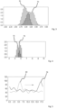
- the reference number 66 represents the vibration frequency of the vibrations occurring during operation of the rotary press, as measured by the vibration sensor 62 arranged on the ejector cam 56, plotted against the vibration acceleration, in each case in arbitrary units.
- Corresponding reference values are in Figure 2 at the reference number 68. It can be seen that on the one hand the amplitude or the maximum of the vibration signals measured by the vibration sensor 62 is higher than the reference values and also the vibration acceleration is lower.
- These deviations of the recorded measured values compared to the reference values are compared by the evaluation device 52 with correspondingly specified limit values. If the deviations exceed the limit values, the evaluation device 52 assesses the ejector curve 56 as having increased wear.
- Figure 3 shows a Figure 2 corresponding diagram, whereby in this case at reference number 70 the measured values recorded by the vibration sensor 58 arranged on the dosing curve 54 are compared with corresponding reference values, plotted at reference number 72. An overlap between the curves 70 and 72 is shown cross-hatched.
- the Figure 2 Deviations that can be identified are also in Figure 3 can be seen, although less pronounced due to the arrangement of the vibration sensor 58 on the dosing curve 54.
- the evaluation device 52 can The wear condition of the ejector cam 56 can also be assessed on the basis of the measured values of the vibration sensor 58.
- Figure 4 shows a Figures 2 and 3 slightly modified diagram for measured values recorded by the vibration sensor 60 arranged on the upper pressure roller 40.
- the vibration frequency is plotted against the vibration speed, again in any units.
- the measured values recorded by the vibration sensor 60 are shown at the reference number 74.
- Corresponding reference values for a new ejector curve 56 are shown at the reference number 76.
- An overlap between the curves 74 and 76 is again shown cross-hatched.
- the evaluation device 52 produces discernible deviations between the measured values that can be compared with corresponding limit values. For example, the frequency amplitude or the frequency maximum of the measured values 74 is again higher than the reference values 76.
- the vibration speed is greater than the reference values. By comparing with correspondingly specified limit values, the evaluation device 52 can determine increased wear.
- a measured value curve of the ejection forces recorded by the force sensor 64 arranged on the ejector curve 56 is plotted over time, and at reference number 80, a corresponding reference value curve for a new ejector curve 56 is plotted. It can be clearly seen that there is a temporal shift in the measured value curve 78 recorded by the force sensor 64 compared to the reference value curve 80. The amplitude of the measured value curves, however, does not change significantly. Again, a limit value for the temporal shift of the measured value curve 78 compared to the reference value curve 80 can be specified and the evaluation device 52 can determine increased wear on the ejector curve 56 on this basis.
Landscapes
- Engineering & Computer Science (AREA)
- Mechanical Engineering (AREA)
- Analytical Chemistry (AREA)
- Health & Medical Sciences (AREA)
- Life Sciences & Earth Sciences (AREA)
- Chemical & Material Sciences (AREA)
- Physics & Mathematics (AREA)
- Biochemistry (AREA)
- General Health & Medical Sciences (AREA)
- General Physics & Mathematics (AREA)
- Immunology (AREA)
- Pathology (AREA)
- Presses And Accessory Devices Thereof (AREA)
- Testing Of Devices, Machine Parts, Or Other Structures Thereof (AREA)
- Forging (AREA)
Applications Claiming Priority (1)
| Application Number | Priority Date | Filing Date | Title |
|---|---|---|---|
| DE102023110808.5A DE102023110808B4 (de) | 2023-04-26 | 2023-04-26 | Verfahren zum Bewerten des Verschleißzustands einer Komponente einer Rundläuferpresse sowie Rundläuferpresse |
Publications (1)
| Publication Number | Publication Date |
|---|---|
| EP4454875A1 true EP4454875A1 (fr) | 2024-10-30 |
Family
ID=90123291
Family Applications (1)
| Application Number | Title | Priority Date | Filing Date |
|---|---|---|---|
| EP24160963.5A Pending EP4454875A1 (fr) | 2023-04-26 | 2024-03-01 | Procédé d'évaluation de l'état d'usure d'un composant d'une presse rotative ainsi que presse rotative |
Country Status (6)
| Country | Link |
|---|---|
| US (1) | US20250060294A1 (fr) |
| EP (1) | EP4454875A1 (fr) |
| JP (1) | JP7855630B2 (fr) |
| CN (1) | CN118849502A (fr) |
| DE (1) | DE102023110808B4 (fr) |
| MX (1) | MX2024003233A (fr) |
Citations (7)
| Publication number | Priority date | Publication date | Assignee | Title |
|---|---|---|---|---|
| JPH05318198A (ja) * | 1992-05-25 | 1993-12-03 | Tsumura & Co | 錠剤製造法 |
| DE19952834A1 (de) * | 1998-11-03 | 2000-05-04 | Minster Machine Co | Verfahren zum Überwachen eines Pressenbetriebes |
| WO2009063287A2 (fr) * | 2007-11-14 | 2009-05-22 | Hibar Systems Ltd. | Presse de pastillage rotative |
| US20140144205A1 (en) * | 2011-05-10 | 2014-05-29 | Fette Compacting Gmbh | Device and Method for Calibrating and Balancing a Measuring Device of a Tablet Press |
| CN205664967U (zh) * | 2016-06-03 | 2016-10-26 | 北京新龙立科技有限公司 | 一种压片机下冲过紧力检测装置 |
| WO2021058516A1 (fr) * | 2019-09-27 | 2021-04-01 | Korsch Ag | Dispositif et procédé pour surveiller une machine à comprimer de préférence en cours de fonctionnement au moyen d'un système de mesure placé sur un poinçon |
| US20220396047A1 (en) * | 2019-10-23 | 2022-12-15 | I.M.A. Industria Macchine Automatiche S.P.A. | Tablet press machine and compression method |
Family Cites Families (3)
| Publication number | Priority date | Publication date | Assignee | Title |
|---|---|---|---|---|
| JP2005334932A (ja) * | 2004-05-26 | 2005-12-08 | Mitsubishi Chemicals Corp | 円筒錠の打錠方法 |
| JP6947654B2 (ja) * | 2018-01-19 | 2021-10-13 | 住友重機械工業株式会社 | プレス装置及びプレス装置の診断方法 |
| JP2020088703A (ja) * | 2018-11-28 | 2020-06-04 | Cach株式会社 | 監視システム |
-
2023
- 2023-04-26 DE DE102023110808.5A patent/DE102023110808B4/de active Active
-
2024
- 2024-03-01 EP EP24160963.5A patent/EP4454875A1/fr active Pending
- 2024-03-14 MX MX2024003233A patent/MX2024003233A/es unknown
- 2024-04-23 US US18/643,314 patent/US20250060294A1/en active Pending
- 2024-04-24 JP JP2024070654A patent/JP7855630B2/ja active Active
- 2024-04-26 CN CN202410508926.5A patent/CN118849502A/zh active Pending
Patent Citations (7)
| Publication number | Priority date | Publication date | Assignee | Title |
|---|---|---|---|---|
| JPH05318198A (ja) * | 1992-05-25 | 1993-12-03 | Tsumura & Co | 錠剤製造法 |
| DE19952834A1 (de) * | 1998-11-03 | 2000-05-04 | Minster Machine Co | Verfahren zum Überwachen eines Pressenbetriebes |
| WO2009063287A2 (fr) * | 2007-11-14 | 2009-05-22 | Hibar Systems Ltd. | Presse de pastillage rotative |
| US20140144205A1 (en) * | 2011-05-10 | 2014-05-29 | Fette Compacting Gmbh | Device and Method for Calibrating and Balancing a Measuring Device of a Tablet Press |
| CN205664967U (zh) * | 2016-06-03 | 2016-10-26 | 北京新龙立科技有限公司 | 一种压片机下冲过紧力检测装置 |
| WO2021058516A1 (fr) * | 2019-09-27 | 2021-04-01 | Korsch Ag | Dispositif et procédé pour surveiller une machine à comprimer de préférence en cours de fonctionnement au moyen d'un système de mesure placé sur un poinçon |
| US20220396047A1 (en) * | 2019-10-23 | 2022-12-15 | I.M.A. Industria Macchine Automatiche S.P.A. | Tablet press machine and compression method |
Also Published As
| Publication number | Publication date |
|---|---|
| DE102023110808A1 (de) | 2024-10-31 |
| DE102023110808B4 (de) | 2025-07-17 |
| US20250060294A1 (en) | 2025-02-20 |
| JP2024159630A (ja) | 2024-11-08 |
| MX2024003233A (es) | 2024-11-08 |
| CN118849502A (zh) | 2024-10-29 |
| JP7855630B2 (ja) | 2026-05-08 |
Similar Documents
| Publication | Publication Date | Title |
|---|---|---|
| EP2707208B1 (fr) | Dispositif et procédé d'étalonnage et d'ajustement d'un dispositif de mesure d'une presse à comprimés | |
| EP1568480B1 (fr) | Méthode et dispositif pour le contrôle de qualité dans la fabrication de comprimés | |
| DE102008049015B4 (de) | Verfahren zur Qualitätsüberwachung von pulverförmigem Pressmaterial und eine Rundläuferpresse zur Durchführung des Verfahrens | |
| EP2149450A2 (fr) | Presse à poudre | |
| EP1693182A2 (fr) | Procédé et dispositif pour le pressage d'essai de comprimés multi-couches ou de comprimés enrobés | |
| EP3727830B1 (fr) | Dispositif et procédé de surveillance d'un outil d'entraînement de clavette | |
| EP1439949B1 (fr) | Procede pour regler et surveiller un outil de presse, outil de presse et dispositif de commande de presse associes | |
| DE19502596C2 (de) | Meßgerät und Rechner zur Überprüfung der auf einer Rundläuferpresse hergestellten Tabletten der laufenden Produktion | |
| DE102007052552B4 (de) | Verfahren und Vorrichtung zur Ermittlung von Steuer- und Regelparametern für Tablettenpressen | |
| DE3131402A1 (de) | Verfahren und tablettenpresse zum aufeinanderfolgenden herstellen einer vielzahl von tabletten mit gleichem gewicht | |
| EP3238930A1 (fr) | Presse rotative et procédé d'installation et/ou de fonctionnement d'une presse rotative | |
| DE3715077C2 (fr) | ||
| DE4331403A1 (de) | Verfahren zum Verbinden dünner Platten und Vorrichtung zur Durchführung des Verfahrens | |
| EP1964664B1 (fr) | Procédé pour la commande d'une presse à poudre fabricant des pièces brutes | |
| DE19952834A1 (de) | Verfahren zum Überwachen eines Pressenbetriebes | |
| EP2070692B1 (fr) | Procédé de vérification de comprimés multicouches | |
| DE102017130885B4 (de) | Verfahren zum Regeln der Rotordrehzahl eines Rotors einer Rundläufertablettenpresse sowie Rundläufertablettenpresse | |
| DE102023110808B4 (de) | Verfahren zum Bewerten des Verschleißzustands einer Komponente einer Rundläuferpresse sowie Rundläuferpresse | |
| EP4378676A1 (fr) | Procédé d'évaluation de l'état de poinçons d'une presse rotative ainsi que presse rotative | |
| EP0350563A2 (fr) | Procédé et dispositif pour contrôler les forces de pressage des poinçons dans une presse à tablettes | |
| DE10319024B3 (de) | Verfahren zur Versuchspressung von Tabletten | |
| DE102008046422B3 (de) | Verfahren zum Prüfen von Mehrschichttabletten in einer Mehrfachrundläuferpresse | |
| DE4214475A1 (de) | Verfahren zum Verbinden dünner Platten und Vorrichtung zur Durchführung des Verfahrens | |
| DE102023125660B3 (de) | Verfahren zur Versuchspressung von Presslingen in einer Rundläuferpresse | |
| AT523805A1 (de) | Verfahren zur Verschleißerkennung bei Brechern in Leerfahrt |
Legal Events
| Date | Code | Title | Description |
|---|---|---|---|
| PUAI | Public reference made under article 153(3) epc to a published international application that has entered the european phase |
Free format text: ORIGINAL CODE: 0009012 |
|
| STAA | Information on the status of an ep patent application or granted ep patent |
Free format text: STATUS: THE APPLICATION HAS BEEN PUBLISHED |
|
| AK | Designated contracting states |
Kind code of ref document: A1 Designated state(s): AL AT BE BG CH CY CZ DE DK EE ES FI FR GB GR HR HU IE IS IT LI LT LU LV MC ME MK MT NL NO PL PT RO RS SE SI SK SM TR |
|
| STAA | Information on the status of an ep patent application or granted ep patent |
Free format text: STATUS: REQUEST FOR EXAMINATION WAS MADE |
|
| 17P | Request for examination filed |
Effective date: 20250416 |