EP4454875A1 - Method for evaluating the wear state of a component of a rotary press, and rotary press - Google Patents
Method for evaluating the wear state of a component of a rotary press, and rotary press Download PDFInfo
- Publication number
- EP4454875A1 EP4454875A1 EP24160963.5A EP24160963A EP4454875A1 EP 4454875 A1 EP4454875 A1 EP 4454875A1 EP 24160963 A EP24160963 A EP 24160963A EP 4454875 A1 EP4454875 A1 EP 4454875A1
- Authority
- EP
- European Patent Office
- Prior art keywords
- press
- rotary press
- cavities
- measured values
- punches
- Prior art date
- Legal status (The legal status is an assumption and is not a legal conclusion. Google has not performed a legal analysis and makes no representation as to the accuracy of the status listed.)
- Pending
Links
Images

Classifications
-
- B—PERFORMING OPERATIONS; TRANSPORTING
- B30—PRESSES
- B30B—PRESSES IN GENERAL
- B30B11/00—Presses specially adapted for forming shaped articles from material in particulate or plastic state, e.g. briquetting presses, tabletting presses
- B30B11/02—Presses specially adapted for forming shaped articles from material in particulate or plastic state, e.g. briquetting presses, tabletting presses using a ram exerting pressure on the material in a moulding space
- B30B11/08—Presses specially adapted for forming shaped articles from material in particulate or plastic state, e.g. briquetting presses, tabletting presses using a ram exerting pressure on the material in a moulding space co-operating with moulds carried by a turntable
-
- B—PERFORMING OPERATIONS; TRANSPORTING
- B30—PRESSES
- B30B—PRESSES IN GENERAL
- B30B11/00—Presses specially adapted for forming shaped articles from material in particulate or plastic state, e.g. briquetting presses, tabletting presses
- B30B11/02—Presses specially adapted for forming shaped articles from material in particulate or plastic state, e.g. briquetting presses, tabletting presses using a ram exerting pressure on the material in a moulding space
- B30B11/04—Presses specially adapted for forming shaped articles from material in particulate or plastic state, e.g. briquetting presses, tabletting presses using a ram exerting pressure on the material in a moulding space co-operating with a fixed mould
-
- G—PHYSICS
- G01—MEASURING; TESTING
- G01N—INVESTIGATING OR ANALYSING MATERIALS BY DETERMINING THEIR CHEMICAL OR PHYSICAL PROPERTIES
- G01N3/00—Investigating strength properties of solid materials by application of mechanical stress
- G01N3/56—Investigating resistance to wear or abrasion
-
- B—PERFORMING OPERATIONS; TRANSPORTING
- B30—PRESSES
- B30B—PRESSES IN GENERAL
- B30B11/00—Presses specially adapted for forming shaped articles from material in particulate or plastic state, e.g. briquetting presses, tabletting presses
- B30B11/005—Control arrangements
-
- B—PERFORMING OPERATIONS; TRANSPORTING
- B30—PRESSES
- B30B—PRESSES IN GENERAL
- B30B15/00—Details of, or accessories for, presses; Auxiliary measures in connection with pressing
-
- B—PERFORMING OPERATIONS; TRANSPORTING
- B30—PRESSES
- B30B—PRESSES IN GENERAL
- B30B15/00—Details of, or accessories for, presses; Auxiliary measures in connection with pressing
- B30B15/0094—Press load monitoring means
-
- B—PERFORMING OPERATIONS; TRANSPORTING
- B30—PRESSES
- B30B—PRESSES IN GENERAL
- B30B15/00—Details of, or accessories for, presses; Auxiliary measures in connection with pressing
- B30B15/26—Program-control arrangements
-
- B—PERFORMING OPERATIONS; TRANSPORTING
- B30—PRESSES
- B30B—PRESSES IN GENERAL
- B30B15/00—Details of, or accessories for, presses; Auxiliary measures in connection with pressing
- B30B15/32—Discharging presses
-
- G—PHYSICS
- G06—COMPUTING OR CALCULATING; COUNTING
- G06N—COMPUTING ARRANGEMENTS BASED ON SPECIFIC COMPUTATIONAL MODELS
- G06N20/00—Machine learning
-
- G—PHYSICS
- G06—COMPUTING OR CALCULATING; COUNTING
- G06N—COMPUTING ARRANGEMENTS BASED ON SPECIFIC COMPUTATIONAL MODELS
- G06N3/00—Computing arrangements based on biological models
- G06N3/02—Neural networks
- G06N3/08—Learning methods
Definitions
- the invention relates to a method for assessing the state of wear of a component of a rotary press
- the rotary press comprises a rotor that can be rotated by means of a rotary drive, wherein the rotor has an upper punch guide for upper press punches and a lower punch guide for lower press punches as well as a die plate arranged between the punch guides, wherein the press punches interact with cavities of the die plate
- the rotary press further comprises a filling device by means of which powder material to be pressed is filled into the cavities of the die plate
- the rotary press comprises a pressure device that, during operation, interacts with the upper press punches and with the lower press punches to press the powder material in the cavities of the die plate to form pressed pieces
- the rotary press has control cams that interact with punch heads of the press punches for controlling an axial movement of the press punches, wherein the control cams comprise an ejector cam that controls the lower press punches for ejecting
- the invention also relates to a rotary press comprising a rotor with an upper punch guide for upper press punches and a lower punch guide for lower press punches as well as a die plate arranged between the punch guides, wherein the press punches interact with cavities of the die plate, further comprising a filling device by means of which powder material to be pressed is filled into the cavities of the die plate, further comprising a pressure device which, during operation, interacts with the upper press punches and with the lower press punches for pressing the powder material in the cavities of the die plate to form pressed pieces, and further comprising control cams cooperating with punch heads of the press punches for controlling an axial movement of the press punches, wherein the control cams comprise an ejector cam which controls the lower press punches for ejecting compacts produced in the cavities from the cavities.
- Rotary presses usually have a large number of upper and lower press punches, each pair of which is assigned to a cavity of a die plate.
- the upper and lower press punches rotate together with the die plate, with their axial movement controlled by control cams and guided by upper and lower punch guides.
- the die plate passes through various devices on the rotary press, namely a filling device, in which powder material to be pressed is guided into the cavities of the die plate, and a pressure device, in which the upper and lower press punches are usually pressed into the cavities by upper and lower pressure rollers to press the powder material into pellets, such as tablets.
- the upper press punches are guided upwards out of the cavities and the pellets produced in the cavities are pushed onto the top of the die plate by the lower press punches.
- Ejector cams are provided for this purpose, which move the lower press punches upwards accordingly. For example, by a stripper, the pressed pieces are then stripped from the die plate into an outlet of the rotary press, from where they are fed for further processing.
- Rotary presses are operated with high rotor speeds and correspondingly high production speeds.
- various components of the rotary press wear out, in particular the control cams, and in particular the Ejector cams, which are subject to particular stress when they come into contact with the press rams.
- Contact with powder material to be pressed can also lead to wear.
- Components with increased wear can lead to a deterioration in the quality of the pressed tablets.
- ejector cams with increased wear can lead to defects not being detected during sorting and bad tablets not being sorted out.
- the state of wear of many components of the rotary press, in particular the ejector cams has been checked at specified maintenance intervals, usually manually by an operator. The disadvantage of this is that wear that occurs in the meantime, which can already lead to a deterioration in the quality of the tablets, may not be detected in time. Manual wear control is also complex and cannot be reliably reproduced.
- the invention is therefore based on the object of providing a method and a rotary press of the type mentioned at the beginning, with which the wear condition of components of the rotary press can be assessed reliably, in a timely and reproducible manner.
- the basic structure of the rotary press as it is the subject of the present invention or is used in the method according to the invention, was explained at the beginning.
- the upper and lower punch guides guide the press punches during their axial movement.
- the punch heads interact with control cams, which move the press punches in the axial direction as they rotate with the rotor, in particular towards and away from each other.
- the control cams are usually made up of several control cam elements. They can accommodate the punch heads in corresponding guide receptacles or only rest against a mirror surface of the punch heads.
- the pressure device usually comprises an upper pressure roller and a lower pressure roller, which are connected to the punch heads of the upper and lower press punches. work together.
- pressure devices of this type can also be provided, for example pre-pressure devices and main pressure devices.
- the ejector cam as part of the control cams moves the lower press rams upwards after the pellets have been produced in the respective cavity, so that the respective pellet reaches the top of the die plate, from where it can be guided into a tablet outlet, for example by a stripper arranged stationary above the die plate.
- the ejection forces acting on the ejector cam are measured as measured values during operation of the rotary press with at least one force sensor and/or the vibrations occurring during operation of the rotary press are measured with at least one vibration sensor.
- the measured values are fed to an evaluation device.
- the evaluation device evaluates the state of wear of a component of the rotary press on the basis of the measured values obtained.
- the component is in particular one of the aforementioned components of the rotary press.
- the component can be a control cam element, for example an ejector cam.
- the invention is based on the finding that wear of a component of the rotary press is shown in particular by a change in the ejection forces on the ejector cam and/or a change in the vibrations occurring during operation of the rotary press.
- a combination measurement can also be useful in this case, such that both the ejection forces measured with a force sensor and the vibrations measured with a vibration sensor are recorded as measured values and evaluated by the evaluation device. If both types of measurement values are recorded, they can be evaluated in the manner explained above and below. For example, when comparing the recorded measurement values with reference values, the measured values for the ejection forces are compared with reference values for the ejection forces. and a comparison of the measured values for the vibrations with reference values for the vibrations.
- the assessment of the wear condition can then be carried out on the basis of both types of measured values. For example, increased wear of the component can be determined if one or both types of the recorded measured values deviate from the corresponding reference values. Especially when both types of measured values are recorded and evaluated, influencing factors that affect one of the types of measured values can be taken into account or eliminated, which lead to a change in the corresponding measured values, but not due to a change in the wear condition. Examples include a change in the web height, i.e. the height of the pressed parts produced in the cavities, or the immersion depth of the press dies, in particular the upper press dies, into the cavities or the lower press dies when ejecting the pressed parts from the cavities, which have a particular effect on the ejection forces. If the vibration signals are also taken into account, such influencing factors that are not associated with the wear condition can be identified and eliminated.
- the evaluation device can be part of the rotary press.
- the evaluation device can be integrated into the machine control of the rotary press.
- it can also be designed separately from the rotary press, for example on a computer, a tablet or a smartphone that is separate from the rotary press, or on a server that is separate from the rotary press, for example as part of a cloud solution.
- the invention allows a prediction of the degree of wear of components of the rotary press, in particular in real time. This is done in a simple and reliable manner by using measurement signals for the ejection force on the ejector curve and/or vibrations of the rotary press.
- the evaluation according to the invention is independent of individual assessments by operators and is therefore reliably and objectively reproducible.
- the evaluation device can have an input device and/or a display device. These can be integrated into the evaluation device or designed separately from it, for example in a PC, tablet or smartphone, in particular via an app (application).
- the measured values recorded according to the invention are particularly suitable for assessing the state of wear of the ejector curve.
- the ejector curve is also relevant with regard to assessing the state of wear, since there has been no automatic monitoring of the state of the ejector curve to date. Only a manual check is carried out within the framework of predetermined maintenance intervals. According to the invention, it has been recognized that wear of the ejector curve can be reliably detected using the ejection force and the vibration signals.
- the force sensor that records the measured values for the ejection force can be arranged on the ejector cam.
- corresponding force sensors for measuring the ejection force are often arranged on the ejector cams.
- a force sensor for example, can be mounted on the ejector cam as a force sensor.
- the force sensor can, for example, comprise a bending beam with strain gauges and, if necessary, an integrated measuring amplifier.
- the force sensor for example, below
- the force transducer arranged on the ejection curve is deflected by the forces transmitted by the ejected punch. The ejection force can be determined on the basis of this deflection.
- a vibration sensor is arranged on the ejector cam and/or on the pressure device, in particular on an upper and/or lower pressure roller of the pressure device and/or on an upper and/or lower holder of the upper and/or lower pressure roller, and/or on a metering cam of the control cams for metering the powder material filled into the cavities of the die plate.
- One or more vibration sensors can thus be provided to record the vibrations that occur during operation of the rotary press as measured values.
- a vibration sensor on the ejector cam directly measures the vibrations that occur on the ejector cam and can thus provide particularly direct information about the wear status of the ejector cam.
- vibration signals on dosing cam elements i.e. control cam elements that control (dosage) the height of the lower punches when filling the cavities with powder material
- pressure rollers of the printing device also provide information about the state of wear of components arranged elsewhere on the rotary press, in particular the ejector cam. It can also be useful to arrange and use several vibration sensors. In this way, other effects that are not relevant to the state of wear can be identified and eliminated in the evaluation.
- the measured values can be recorded as a measured value curve, in particular as a time-dependent measured value curve.
- the measured values can be recorded as a measured value curve, plotted against time, speed or Acceleration.
- the measured values can be plotted as a measured value curve using the force or vibration sensors, or individual measured values provided by the force or vibration sensors can be recorded by the evaluation device to form corresponding measured value curves.
- Particularly reliable information about the wear status of the component can be obtained from a change, particularly in the temporal progression of the recorded measured values.
- the wear condition of the component can be assessed by the evaluation device based on a comparison of the measured values obtained with reference values.
- Reference values can be, for example, measured values during operation of the rotary press with a new corresponding component, for example a new output curve. These reference values form target values with which the measured values obtained later during operation of the rotary press can be compared.
- the reference values can be historical data for the rotary press being assessed or data that is stored in a database and, for example, for the type of rotary press in question.
- the evaluation device in the event of a shift in the measured values obtained compared to the reference values, and/or if the amplitude of the measured values obtained changes compared to the reference values and/or if the gradient of the measured values obtained changes compared to the reference values, increased wear on the component is detected.
- a temporal shift in the high-frequency vibration signal or the high-frequency ejection force signal in particular correlates with the degree of wear on an ejector curve of the rotary press.
- the height or shape of maxima in the high-frequency vibration or ejection force signal is also a parameter that indicates the state of wear.
- wear caused by frequent, force-intensive contact with punch heads changes the angle of impact of the press punches on the ramp-like ejector curve. This leads to a corresponding shift or changed shape of the maxima in the corresponding measured value curves. Wear on the ejector curve can also be recognized by a change in the acceleration and the height of the amplitude of the vibration signal and/or the ejection force signal. This can also be taken into account by the evaluation device in the manner explained.
- the evaluation device can determine increased wear of the component if the measured values obtained deviate from the reference values by at least one predetermined limit value.
- the at least one predetermined limit value can be specified and/or adjusted by an operator.
- the at least one predetermined limit value can be specified and/or adjusted by an algorithm, in particular a machine learning algorithm.
- Corresponding limit values can therefore be specified by an operator, by software or can be set process-specifically using reference values of new components, for example new ejector curves.
- Algorithms of the Machine learning in particular self-learning algorithms, can also be used to optimize or adjust predefined limit values. An operator can, for example, enter the limit values via an input device on the evaluation device or adjust them according to their respective needs.
- Machine learning algorithms can in particular include neural networks.
- the evaluation device can display the results of the assessment of the wear status of the component to an operator. Furthermore, the evaluation device can issue a warning message if it detects increased wear on the component.
- the display of the evaluation results or the warning message can be shown via the above-mentioned display device of the evaluation device.
- the warning message can also include a suggestion for cleaning and/or re-treatment and/or replacing the component with increased wear.
- the rotary press in particular the evaluation device, can be designed to carry out the method according to the invention. Accordingly, the method according to the invention can be carried out with the rotary press according to the invention.
- the rotary press shown is a rotary press for tablet production in which powdered material is pressed into tablets.
- the rotary press comprises a rotor which is driven in rotation by a rotary drive and has a die plate 10 which has a plurality of cavities 12.
- the cavities 12 can be formed, for example, by holes in the die plate 10.
- the rotor also comprises a plurality of upper press punches 14 and lower press punches 16 which rotate synchronously with the die plate 10.
- the upper press punches 14 are guided axially in an upper punch guide 18 and the lower press punches 16 are guided axially in a lower punch guide 20.
- the axial movement of the upper press punches 14 and lower press punches 16 as the rotor rotates is controlled by upper control cam elements 22 and lower control cam elements 24.
- the rotary press further comprises a filling device 26, which has a filling reservoir 28 and a filling chamber 30, which are connected via a filling pipe 32.
- powder material from the filling reservoir 28 passes through the filling pipe 32 into the filling chamber 30 and from there via a filling opening provided on the underside of the filling chamber 30 into the cavities 12 of the matrix plate 10 due to gravity.
- the rotary press also comprises a pressure device 34.
- the pressure device 34 comprises a pre-pressure device with an upper pre-pressure roller 36 held on an upper holder 35 and a lower pre-pressure roller 38 held on a lower holder 37, as well as a main pressure device with an upper pressure roller 40 held on an upper holder 39 and a lower pressure roller 42 held on a lower holder 41.
- the rotary press comprises an ejection device 44 and a stripping device 46 with a stripping element which feeds the tablets 48 produced in the rotary press to a discharge device 50 for removal from the rotary press.
- the stripping device 46 can, for example, comprise a preferably sickle-shaped stripping element which, in the region of the ejection device 44, strips tablets 48 conveyed to the top of the die plate 10 by the lower press punches 16 from the die plate 10 and feeds them to the discharge device 50.
- the rotary press comprises an evaluation device 52 for controlling the operation of the rotary press and for carrying out the method according to the invention, as explained in more detail below.
- the control cams 24 comprise various control cam elements, including a dosing cam 54 and an ejector cam 56.
- vibration sensors 58, 60, 62 are arranged on the dosing cam 54, the upper and lower brackets 39, 41 of the upper and lower pressure rollers 40, 42 and on the ejector cam 56.
- the vibration sensors 58, 60, 62 measure the vibrations during operation of the Rotary presses cause vibrations to be transmitted to the respective components on which they are arranged.
- a force sensor 64 is arranged on the ejector curve 56 for measuring the ejection forces acting on the ejector curve 56 by the press rams 14, 16 during operation of the rotary press.
- the measured values recorded by the vibration sensors 58, 60, 62 and the force sensor 64 during operation of the rotary press are recorded as measured value curves and fed to the evaluation device 52.
- the evaluation device 52 evaluates the wear condition of the ejector curve 56 of the rotary press in the example shown. Results of the evaluation or a warning message in the event of increased wear can be output via a display device of the evaluation device 52.
- This can be integrated into the evaluation device 52 or, for example, be formed by a computer, a tablet or a smartphone.
- the evaluation device 52 also includes an input device via which an operator can enter parameters for the status assessment of the evaluation device 52, such as limit values for deviations from reference value curves.
- the input device can also be integrated into the evaluation device 52 or be designed separately from it, for example on a computer, a tablet or a smartphone.
- the evaluation device 52 compares the recorded measurement curves of the vibration sensors 58, 60, 62 and the force sensor 64 with reference value curves, which may have been created experimentally, for example, using a new and thus not worn ejector curve 56.
- the reference value curves may have been created for the rotary press to be evaluated or for another rotary press of the same type.
- the evaluation device 52 can, for example, if there is a temporal shift in the obtained measurement curves compared to the reference value curves and/or if there is a change in the Amplitude of the obtained measured value curves compared to the reference value curves, in particular a changed maximum, and/or in the case of a changed slope of the obtained measured value curves compared to the reference value curves, in particular a changed slope of amplitudes or maxima, an increased wear of the ejector curve 56 can be determined.
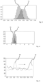
- the reference number 66 represents the vibration frequency of the vibrations occurring during operation of the rotary press, as measured by the vibration sensor 62 arranged on the ejector cam 56, plotted against the vibration acceleration, in each case in arbitrary units.
- Corresponding reference values are in Figure 2 at the reference number 68. It can be seen that on the one hand the amplitude or the maximum of the vibration signals measured by the vibration sensor 62 is higher than the reference values and also the vibration acceleration is lower.
- These deviations of the recorded measured values compared to the reference values are compared by the evaluation device 52 with correspondingly specified limit values. If the deviations exceed the limit values, the evaluation device 52 assesses the ejector curve 56 as having increased wear.
- Figure 3 shows a Figure 2 corresponding diagram, whereby in this case at reference number 70 the measured values recorded by the vibration sensor 58 arranged on the dosing curve 54 are compared with corresponding reference values, plotted at reference number 72. An overlap between the curves 70 and 72 is shown cross-hatched.
- the Figure 2 Deviations that can be identified are also in Figure 3 can be seen, although less pronounced due to the arrangement of the vibration sensor 58 on the dosing curve 54.
- the evaluation device 52 can The wear condition of the ejector cam 56 can also be assessed on the basis of the measured values of the vibration sensor 58.
- Figure 4 shows a Figures 2 and 3 slightly modified diagram for measured values recorded by the vibration sensor 60 arranged on the upper pressure roller 40.
- the vibration frequency is plotted against the vibration speed, again in any units.
- the measured values recorded by the vibration sensor 60 are shown at the reference number 74.
- Corresponding reference values for a new ejector curve 56 are shown at the reference number 76.
- An overlap between the curves 74 and 76 is again shown cross-hatched.
- the evaluation device 52 produces discernible deviations between the measured values that can be compared with corresponding limit values. For example, the frequency amplitude or the frequency maximum of the measured values 74 is again higher than the reference values 76.
- the vibration speed is greater than the reference values. By comparing with correspondingly specified limit values, the evaluation device 52 can determine increased wear.
- a measured value curve of the ejection forces recorded by the force sensor 64 arranged on the ejector curve 56 is plotted over time, and at reference number 80, a corresponding reference value curve for a new ejector curve 56 is plotted. It can be clearly seen that there is a temporal shift in the measured value curve 78 recorded by the force sensor 64 compared to the reference value curve 80. The amplitude of the measured value curves, however, does not change significantly. Again, a limit value for the temporal shift of the measured value curve 78 compared to the reference value curve 80 can be specified and the evaluation device 52 can determine increased wear on the ejector curve 56 on this basis.
Landscapes
- Engineering & Computer Science (AREA)
- Mechanical Engineering (AREA)
- Analytical Chemistry (AREA)
- Health & Medical Sciences (AREA)
- Life Sciences & Earth Sciences (AREA)
- Chemical & Material Sciences (AREA)
- Physics & Mathematics (AREA)
- Biochemistry (AREA)
- General Health & Medical Sciences (AREA)
- General Physics & Mathematics (AREA)
- Immunology (AREA)
- Pathology (AREA)
- Presses And Accessory Devices Thereof (AREA)
- Testing Of Devices, Machine Parts, Or Other Structures Thereof (AREA)
- Forging (AREA)
Abstract
Die Erfindung betrifft ein Verfahren zum Bewerten des Verschleißzustands einer Komponente einer Rundläuferpresse, wobei die Rundläuferpresse einen mittels eines Drehantriebs drehbaren Rotor umfasst, wobei der Rotor eine obere Stempelführung für obere Pressstempel und eine untere Stempelführung für untere Pressstempel sowie eine zwischen den Stempelführungen angeordnete Matrizenscheibe aufweist, wobei die Pressstempel mit Kavitäten der Matrizenscheibe zusammenwirken, wobei die Rundläuferpresse weiter eine Fülleinrichtung umfasst, durch die zu verpressendes Pulvermaterial in die Kavitäten der Matrizenscheibe gefüllt wird, wobei die Rundläuferpresse eine Druckeinrichtung umfasst, die im Betrieb mit den oberen Pressstempeln und mit den unteren Pressstempeln zum Verpressen des Pulvermaterials in den Kavitäten der Matrizenscheibe zu Presslingen zusammenwirkt, und wobei die Rundläuferpresse mit Stempelköpfen der Pressstempel zusammenwirkende Steuerkurven zum Steuern einer axialen Bewegung der Pressstempel aufweist, wobei die Steuerkurven eine Auswerferkurve umfassen, die die unteren Pressstempel zum Auswerfen von in den Kavitäten erzeugten Presslingen aus den Kavitäten steuern. Die Erfindung betrifft außerdem eine Rundläuferpresse.

Description
Die Erfindung betrifft ein Verfahren zum Bewerten des Verschleißzustands einer Komponente einer Rundläuferpresse, wobei die Rundläuferpresse einen mittels eines Drehantriebs drehbaren Rotor umfasst, wobei der Rotor eine obere Stempelführung für obere Pressstempel und eine untere Stempelführung für untere Pressstempel sowie eine zwischen den Stempelführungen angeordnete Matrizenscheibe aufweist, wobei die Pressstempel mit Kavitäten der Matrizenscheibe zusammenwirken, wobei die Rundläuferpresse weiter eine Fülleinrichtung umfasst, durch die zu verpressendes Pulvermaterial in die Kavitäten der Matrizenscheibe gefüllt wird, wobei die Rundläuferpresse eine Druckeinrichtung umfasst, die im Betrieb mit den oberen Pressstempeln und mit den unteren Pressstempeln zum Verpressen des Pulvermaterials in den Kavitäten der Matrizenscheibe zu Presslingen zusammenwirkt, und wobei die Rundläuferpresse mit Stempelköpfen der Pressstempel zusammenwirkende Steuerkurven zum Steuern einer axialen Bewegung der Pressstempel aufweist, wobei die Steuerkurven eine Auswerferkurve umfassen, die die unteren Pressstempel zum Auswerfen von in den Kavitäten erzeugten Presslingen aus den Kavitäten steuern.The invention relates to a method for assessing the state of wear of a component of a rotary press, wherein the rotary press comprises a rotor that can be rotated by means of a rotary drive, wherein the rotor has an upper punch guide for upper press punches and a lower punch guide for lower press punches as well as a die plate arranged between the punch guides, wherein the press punches interact with cavities of the die plate, wherein the rotary press further comprises a filling device by means of which powder material to be pressed is filled into the cavities of the die plate, wherein the rotary press comprises a pressure device that, during operation, interacts with the upper press punches and with the lower press punches to press the powder material in the cavities of the die plate to form pressed pieces, and wherein the rotary press has control cams that interact with punch heads of the press punches for controlling an axial movement of the press punches, wherein the control cams comprise an ejector cam that controls the lower press punches for ejecting pressed pieces produced in the cavities from the cavities.
Die Erfindung betritt außerdem eine Rundläuferpresse, umfassend einen Rotor mit einer oberen Stempelführung für obere Pressstempel und einer unteren Stempelführung für untere Pressstempel sowie einer zwischen den Stempelführungen angeordneten Matrizenscheibe, wobei die Pressstempel mit Kavitäten der Matrizenscheibe zusammenwirken, weiter umfassend eine Fülleinrichtung, durch die zu verpressendes Pulvermaterial in die Kavitäten der Matrizenscheibe gefüllt wird, weiter umfassend eine Druckeinrichtung, die im Betrieb mit den oberen Pressstempeln und mit den unteren Pressstempeln zum Verpressen des Pulvermaterials in den Kavitäten der Matrizenscheibe zu Presslingen zusammenwirkt, und weiter umfassend mit Stempelköpfen der Pressstempel zusammenwirkende Steuerkurven zum Steuern einer axialen Bewegung der Pressstempel, wobei die Steuerkurven eine Auswerferkurve umfassen, die die unteren Pressstempel zum Auswerfen von in den Kavitäten erzeugten Presslingen aus den Kavitäten steuern.The invention also relates to a rotary press comprising a rotor with an upper punch guide for upper press punches and a lower punch guide for lower press punches as well as a die plate arranged between the punch guides, wherein the press punches interact with cavities of the die plate, further comprising a filling device by means of which powder material to be pressed is filled into the cavities of the die plate, further comprising a pressure device which, during operation, interacts with the upper press punches and with the lower press punches for pressing the powder material in the cavities of the die plate to form pressed pieces, and further comprising control cams cooperating with punch heads of the press punches for controlling an axial movement of the press punches, wherein the control cams comprise an ejector cam which controls the lower press punches for ejecting compacts produced in the cavities from the cavities.
In Rundläuferpressen ist regelmäßig eine Vielzahl von oberen und unteren Pressstempeln vorgesehen, die paarweise jeweils einer Kavität einer Matrizenscheibe zugeordnet sind. Im Betrieb der Rundläuferpresse drehen die oberen und unteren Pressstempel gemeinsam mit der Matrizenscheibe, wobei ihre axiale Bewegung durch Steuerkurven gesteuert und durch obere und untere Stempelführungen geführt wird. Im Zuge der Drehung durchläuft die Matrizenscheibe verschiedene Einrichtungen der Rundläuferpresse, nämlich eine Fülleinrichtung, in der zu verpressendes Pulvermaterial in die Kavitäten der Matrizenscheibe geführt wird und eine Druckeinrichtung, in der die oberen und unteren Pressstempel in der Regel durch obere und untere Druckrollen zum Verpressen des Pulvermaterials zu Presslingen, wie Tabletten, in die Kavitäten gedrückt werden. Nachfolgend zu der Druckeinrichtung werden die oberen Pressstempel nach oben aus den Kavitäten geführt und die in den Kavitäten erzeugten Presslinge werden durch die unteren Pressstempel auf die Oberseite der Matrizenscheibe geschoben. Hierfür sind Auswerferkurven vorgesehen, die die unteren Pressstempel entsprechend nach oben bewegen. Beispielsweise durch einen Abstreifer werden die Presslinge anschließend von der Matrizenscheibe in einen Ausgang der Rundläuferpresse abgestreift, von wo sie einer weiteren Verarbeitung zugeführt werden.Rotary presses usually have a large number of upper and lower press punches, each pair of which is assigned to a cavity of a die plate. When the rotary press is in operation, the upper and lower press punches rotate together with the die plate, with their axial movement controlled by control cams and guided by upper and lower punch guides. As it rotates, the die plate passes through various devices on the rotary press, namely a filling device, in which powder material to be pressed is guided into the cavities of the die plate, and a pressure device, in which the upper and lower press punches are usually pressed into the cavities by upper and lower pressure rollers to press the powder material into pellets, such as tablets. Following the pressure device, the upper press punches are guided upwards out of the cavities and the pellets produced in the cavities are pushed onto the top of the die plate by the lower press punches. Ejector cams are provided for this purpose, which move the lower press punches upwards accordingly. For example, by a stripper, the pressed pieces are then stripped from the die plate into an outlet of the rotary press, from where they are fed for further processing.
Rundläuferpressen werden mit hohen Rotordrehzahlen und entsprechend hohen Produktionsgeschwindigkeiten betrieben. Im Zuge der entsprechend großen Anzahl von Pressvorgängen kommt es zu Verschleiß verschiedener Komponenten der Rundläuferpresse, insbesondere auch der Steuerkurven, und hier besonders der Auswerferkurven, die im Zuge des Kontakts mit den Pressstempeln einer besonderen Belastung unterliegen. Auch Kontakt mit zu verpressendem Pulvermaterial kann zu einem entsprechenden Verschleiß führen. Komponenten mit erhöhtem Verschleiß können zu einer Verschlechterung der Presslingsqualität führen. Beispielsweise Auswerferkurven mit erhöhtem Verschleiß können dazu führen, dass verursachte Defekte nicht bei der Aussortierung erkannt werden und Schlechttabletten entsprechend nicht aussortiert werden. Bislang wird der Verschleißzustand vieler Komponenten der Rundläuferpresse, insbesondere der Auswerferkurven, bei vorgegebenen Wartungsintervallen geprüft, in der Regel manuell durch eine Bedienperson. Nachteilig hieran ist, dass zwischenzeitlich auftretender Verschleiß, der bereits zu einer Beeinträchtigung der Tablettenqualität führen kann, möglicherweise nicht rechtzeitig erkannt wird. Auch ist eine manuelle Verschleißkontrolle aufwendig und nicht zuverlässig reproduzierbar.Rotary presses are operated with high rotor speeds and correspondingly high production speeds. In the course of the correspondingly large number of pressing processes, various components of the rotary press wear out, in particular the control cams, and in particular the Ejector cams, which are subject to particular stress when they come into contact with the press rams. Contact with powder material to be pressed can also lead to wear. Components with increased wear can lead to a deterioration in the quality of the pressed tablets. For example, ejector cams with increased wear can lead to defects not being detected during sorting and bad tablets not being sorted out. To date, the state of wear of many components of the rotary press, in particular the ejector cams, has been checked at specified maintenance intervals, usually manually by an operator. The disadvantage of this is that wear that occurs in the meantime, which can already lead to a deterioration in the quality of the tablets, may not be detected in time. Manual wear control is also complex and cannot be reliably reproduced.
Ausgehend von dem erläuterten Stand der Technik liegt der Erfindung daher die Aufgabe zugrunde, ein Verfahren und eine Rundläuferpresse der eingangs genannten Art bereitzustellen, mit denen der Verschleißzustand von Komponenten der Rundläuferpresse zuverlässig, rechtzeitig und reproduzierbar bewertet werden kann.Based on the explained prior art, the invention is therefore based on the object of providing a method and a rotary press of the type mentioned at the beginning, with which the wear condition of components of the rotary press can be assessed reliably, in a timely and reproducible manner.
Die Erfindung löst die Aufgabe durch die unabhängigen Ansprüche 1 und 13. Vorteilhafte Ausgestaltungen finden sich in den abhängigen Ansprüchen, der Beschreibung und den Figuren.The invention solves the problem by the independent claims 1 and 13. Advantageous embodiments can be found in the dependent claims, the description and the figures.
Für ein Verfahren der eingangs genannten Art löst die Erfindung die Aufgabe durch die Schritte:
- mit mindestens einem Kraftsensor werden im Betrieb der Rundläuferpresse auf die Auswerferkurve wirkenden Ausstoßkräfte als Messwerte gemessen und/oder mit mindestens einem Vibrationssensor werden im Betrieb der Rundläuferpresse auftretende Vibrationen als Messwerte gemessen,
- die Messwerte werden einer Auswerteeinrichtung zugeführt und durch die Auswerteeinrichtung wird auf Grundlage der erhaltenen Messwerte der Verschleißzustand einer Komponente der Rundläuferpresse bewertet.
- With at least one force sensor, the ejection forces acting on the ejector cam during operation of the rotary press are measured as measured values and/or with at least one vibration sensor, vibrations occurring during operation of the rotary press are measured as measured values,
- The measured values are fed to an evaluation device and the evaluation device assesses the wear condition of a component of the rotary press on the basis of the measured values obtained.
Für eine Rundläuferpresse der eingangsgenannten Art löst die Erfindung die Aufgabe dadurch,
- dass die Rundläuferpresse mindestens einen Kraftsensor umfasst, mit dem im Betrieb der Rundläuferpresse auf die Auswerferkurve wirkenden Ausstoßkräfte als Messwerte messbar sind und/oder dass die Rundläuferpresse mindestens einen Vibrationssensor umfasst, mit dem im Betrieb der Rundläuferpresse auftretende Vibrationen als Messwerte messbar sind, und
- dass eine Auswerteeinrichtung vorgesehen ist, an der die Messwerte anliegen, und die dazu ausgebildet ist, auf Grundlage der erhaltenen Messwerte den Verschleißzustand einer Komponente der Rundläuferpresse zu bewerten.
- that the rotary press comprises at least one force sensor with which the ejection forces acting on the ejector curve during operation of the rotary press can be measured as measured values and/or that the rotary press comprises at least one vibration sensor with which the vibrations occurring during operation of the rotary press can be measured as measured values, and
- that an evaluation device is provided to which the measured values are applied and which is designed to evaluate the wear condition of a component of the rotary press on the basis of the measured values obtained.
Der grundsätzliche Aufbau der Rundläuferpresse, wie sie Gegenstand der vorliegenden Erfindung ist bzw. beim erfindungsgemäßen Verfahren zum Einsatz kommt, wurde eingangs erläutert. Wie erläutert führen die oberen und unteren Stempelführungen die Pressstempel bei ihrer axialen Bewegung. Die Stempelköpfe wirken mit Steuerkurven zusammen, die die Pressstempel im Zuge ihrer Drehung mit dem Rotor in Axialrichtung bewegen, insbesondere aufeinander zu und voneinander weg. Die Steuerkurven sind in der Regel aus mehreren Steuerkurvenelementen aufgebaut. Sie können die Stempelköpfe in entsprechenden Führungsaufnahmen aufnehmen oder nur an einer Spiegelfläche der Stempelköpfe anliegen. Die Druckeinrichtung umfasst in der Regel eine obere Druckrolle und eine untere Druckrolle, die mit den Stempelköpfen der oberen bzw. unteren Pressstempel zusammenwirken. Auch können mehrere Druckeinrichtungen dieser Art vorgesehen sein, zum Beispiel Vordruckeinrichtungen und Hauptdruckeinrichtungen. Die Auswerferkurve als Teil der Steuerkurven bewegt die unteren Pressstempel nach dem Erzeugen der Presslinge in der jeweiligen Kavität nach oben, so dass der jeweilige Pressling auf die Oberseite der Matrizenscheibe gelangt, von wo er in einen Tablettenausgang geleitet werden kann, beispielsweise durch einen stationär oberhalb der Matrizenscheibe angeordneten Abstreifer.The basic structure of the rotary press, as it is the subject of the present invention or is used in the method according to the invention, was explained at the beginning. As explained, the upper and lower punch guides guide the press punches during their axial movement. The punch heads interact with control cams, which move the press punches in the axial direction as they rotate with the rotor, in particular towards and away from each other. The control cams are usually made up of several control cam elements. They can accommodate the punch heads in corresponding guide receptacles or only rest against a mirror surface of the punch heads. The pressure device usually comprises an upper pressure roller and a lower pressure roller, which are connected to the punch heads of the upper and lower press punches. work together. Several pressure devices of this type can also be provided, for example pre-pressure devices and main pressure devices. The ejector cam as part of the control cams moves the lower press rams upwards after the pellets have been produced in the respective cavity, so that the respective pellet reaches the top of the die plate, from where it can be guided into a tablet outlet, for example by a stripper arranged stationary above the die plate.
Erfindungsgemäß werden als Messwerte im Betrieb der Rundläuferpresse mit mindestens einem Kraftsensor die auf die Auswerferkurve wirkenden Ausstoßkräfte und/oder mit mindestens einem Vibrationssensor im Betrieb der Rundläuferpresse auftretende Vibrationen gemessen. Die Messwerte werden einer Auswerteeinrichtung zugeführt. Die Auswerteeinrichtung bewertet auf Grundlage der erhaltenen Messwerte den Verschleißzustand einer Komponente der Rundläuferpresse. Bei der Komponente handelt es sich insbesondere um eine der vorgenannten Komponenten der Rundläuferpresse. Beispielsweise kann es sich bei der Komponente um ein Steuerkurvenelement, zum Beispiel eine Auswerferkurve, handeln. Die Erfindung basiert auf der Erkenntnis, dass sich ein Verschleiß einer Komponente der Rundläuferpresse insbesondere durch eine Veränderung der Ausstoßkräfte an der Auswerferkurve und/oder eine Veränderung der im Betrieb der Rundläuferpresse auftretenden Vibrationen zeigt. Dabei kann auch eine Kombinationsmessung sinnvoll sein derart, dass sowohl die mit einem Kraftsensor gemessenen Ausstoßkräfte als auch die mit einem Vibrationssensor gemessenen Vibrationen als Messwerte erfasst und durch die Auswerteeinrichtung ausgewertet werden. Sofern beide Arten von Messwerten aufgenommen werden, können diese jeweils in der vorstehend und nachstehend noch erläuterten Weise ausgewertet werden. Zum Beispiel bei einem Vergleich der aufgenommenen Messwerte mit Referenzwerten erfolgt dann ein Vergleich der Messwerte zu den Ausstoßkräften mit Referenzwerten zu den Ausstoßkräften und ein Vergleich der Messwerte zu den Vibrationen mit Referenzwerten zu den Vibrationen. Die Bewertung des Verschleißzustands kann dann auf Grundlage von beiden Arten von Messwerten erfolgen. Zum Beispiel kann ein erhöhter Verschleiß der Komponente festgestellt werden, wenn eine oder wenn beide Arten der aufgenommenen Messwerte von entsprechenden Referenzwerten abweichen. Gerade wenn beide Arten von Messwerten aufgenommen und ausgewertet werden, können zum Beispiel auf eine der Messwertarten wirkende Einflussfaktoren berücksichtigt bzw. eliminiert werden, die zwar zu einer Veränderung der entsprechenden Messwerte führen, aber nicht aufgrund eines veränderten Verschleißzustands. Beispielhaft genannt sei eine Änderung der Steghöhe, also der Höhe der in den Kavitäten erzeugten Presslinge, oder der Eintauchtiefe der Pressstempel, insbesondere der oberen Pressstempel, in die Kavitäten oder der unteren Pressstempel beim Ausstoßen der Presslinge aus den Kavitäten, die sich insbesondere auf die Ausstoßkräfte auswirken. Bei einer zusätzlichen Berücksichtigung der Vibrationssignale können solche, dem Verschleißzustand nicht zugeordnete Einflussfaktoren erkannt und eliminiert werden.According to the invention, the ejection forces acting on the ejector cam are measured as measured values during operation of the rotary press with at least one force sensor and/or the vibrations occurring during operation of the rotary press are measured with at least one vibration sensor. The measured values are fed to an evaluation device. The evaluation device evaluates the state of wear of a component of the rotary press on the basis of the measured values obtained. The component is in particular one of the aforementioned components of the rotary press. For example, the component can be a control cam element, for example an ejector cam. The invention is based on the finding that wear of a component of the rotary press is shown in particular by a change in the ejection forces on the ejector cam and/or a change in the vibrations occurring during operation of the rotary press. A combination measurement can also be useful in this case, such that both the ejection forces measured with a force sensor and the vibrations measured with a vibration sensor are recorded as measured values and evaluated by the evaluation device. If both types of measurement values are recorded, they can be evaluated in the manner explained above and below. For example, when comparing the recorded measurement values with reference values, the measured values for the ejection forces are compared with reference values for the ejection forces. and a comparison of the measured values for the vibrations with reference values for the vibrations. The assessment of the wear condition can then be carried out on the basis of both types of measured values. For example, increased wear of the component can be determined if one or both types of the recorded measured values deviate from the corresponding reference values. Especially when both types of measured values are recorded and evaluated, influencing factors that affect one of the types of measured values can be taken into account or eliminated, which lead to a change in the corresponding measured values, but not due to a change in the wear condition. Examples include a change in the web height, i.e. the height of the pressed parts produced in the cavities, or the immersion depth of the press dies, in particular the upper press dies, into the cavities or the lower press dies when ejecting the pressed parts from the cavities, which have a particular effect on the ejection forces. If the vibration signals are also taken into account, such influencing factors that are not associated with the wear condition can be identified and eliminated.
Die Auswerteeinrichtung kann Teil der Rundläuferpresse sein. Beispielsweise kann die Auswerteeinrichtung in die Maschinensteuerung der Rundläuferpresse integriert sein. Sie kann aber auch getrennt von der Rundläuferpresse ausgebildet sein, beispielsweise auf einem von der Rundläuferpresse getrennten Computer, einem Tablet oder einem Smartphone oder auf einem von der Rundläuferpresse getrennten Server, beispielsweise im Rahmen einer Cloud-Lösung.The evaluation device can be part of the rotary press. For example, the evaluation device can be integrated into the machine control of the rotary press. However, it can also be designed separately from the rotary press, for example on a computer, a tablet or a smartphone that is separate from the rotary press, or on a server that is separate from the rotary press, for example as part of a cloud solution.
Die Erfindung erlaubt eine Vorhersage zum Verschleißgrad von Komponenten der Rundläuferpresse, insbesondere in Echtzeit. Dies erfolgt in einfacher und zuverlässiger Weise über die Nutzung von Messsignalen zur Ausstoßkraft an der Auswerferkurve und/oder zu Vibrationen der Rundläuferpresse. Indem die erfindungsgemäße Bewertung des Verschleißzustands unabhängig von Wartungsintervallen erfolgen kann, insbesondere fortlaufend im Betrieb der Rundläuferpresse, kann ein erhöhter Verschleiß rechtzeitig erkannt werden. Die Prozessstabilität wird erhöht, ungeplante Ausfälle der Rundläuferpresse werden minimiert. Gleichzeitig können Qualitätsmerkmale der hergestellten Presslinge nachhaltig optimiert werden. Die erfindungsgemäße Bewertung ist unabhängig von individuellen Einschätzungen von Bedienpersonen und damit zuverlässig objektiv reproduzierbar.The invention allows a prediction of the degree of wear of components of the rotary press, in particular in real time. This is done in a simple and reliable manner by using measurement signals for the ejection force on the ejector curve and/or vibrations of the rotary press. By evaluating the state of wear according to the invention independently of maintenance intervals Increased wear can be detected in good time, particularly continuously during operation of the rotary press. Process stability is increased and unplanned downtimes of the rotary press are minimized. At the same time, quality characteristics of the pressed parts produced can be sustainably optimized. The evaluation according to the invention is independent of individual assessments by operators and is therefore reliably and objectively reproducible.
Die Auswerteeinrichtung kann eine Eingabeeinrichtung und/oder eine Anzeigeeinrichtung aufweisen. Diese können in die Auswerteeinrichtung integriert sein oder getrennt von dieser ausgebildet sein, zum Beispiel in einem PC, Tablet oder Smartphone, insbesondere per App (Applikation).The evaluation device can have an input device and/or a display device. These can be integrated into the evaluation device or designed separately from it, for example in a PC, tablet or smartphone, in particular via an app (application).
Besonders geeignet sind die erfindungsgemäß aufgenommenen Messwerte für die Bewertung des Verschleißzustands der Auswerferkurve. Auch ist die Auswerferkurve hinsichtlich der Bewertung des Verschleißzustands von Relevanz, da bislang keine automatische Überwachung des Zustands der Auswerferkurve erfolgt. Lediglich eine manuelle Überprüfung im Rahmen von vorgegebenen Wartungsintervallen wird durchgeführt. Erfindungsgemäß ist erkannt worden, dass über die Ausstoßkraft und die Vibrationssignale ein Verschleiß der Auswerferkurve zuverlässig erkannt werden kann.The measured values recorded according to the invention are particularly suitable for assessing the state of wear of the ejector curve. The ejector curve is also relevant with regard to assessing the state of wear, since there has been no automatic monitoring of the state of the ejector curve to date. Only a manual check is carried out within the framework of predetermined maintenance intervals. According to the invention, it has been recognized that wear of the ejector curve can be reliably detected using the ejection force and the vibration signals.
Der die Messwerte zur Ausstoßkraft aufnehmende Kraftsensor kann an der Auswerferkurve angeordnet sein. Bereits derzeit sind häufig entsprechende Kraftsensoren zum Messen der Ausstoßkraft an den Auswerferkurven angeordnet. Diese werden aber bislang nicht für eine Verschleißerkennung genutzt. Als Kraftsensor kann zum Beispiel ein Kraftaufnehmer an der Auswerferkrueve montiert sein. Der Kraftaufnehmer kann zum Beispiel einen Biegebalken mit Dehnungsmessstreifen und gegebenenfalls integriertem Messverstärker umfassen. Der beispielsweise unterhalb der Ausstoßkurve angeordnete Kraftaufnehmer wird durch die von dem ausgestoßenen Stempel übertragenen Kräfte ausgelenkt. Anhand dieser Auslenkung kann die Ausstoßkraft ermittelt werden.The force sensor that records the measured values for the ejection force can be arranged on the ejector cam. Currently, corresponding force sensors for measuring the ejection force are often arranged on the ejector cams. However, these have not yet been used for wear detection. A force sensor, for example, can be mounted on the ejector cam as a force sensor. The force sensor can, for example, comprise a bending beam with strain gauges and, if necessary, an integrated measuring amplifier. The force sensor, for example, below The force transducer arranged on the ejection curve is deflected by the forces transmitted by the ejected punch. The ejection force can be determined on the basis of this deflection.
Nach einer weiteren Ausgestaltung kann vorgesehen sein, dass ein Vibrationssensor an der Auswerferkurve und/oder an der Druckeinrichtung, insbesondere einer oberen und/oder unteren Druckrolle der Druckeinrichtung und/oder an einer oberen und/oder unteren Halterung der oberen und/oder unteren Druckrolle, und/oder an einer Dosierkurve der Steuerkurven zum Dosieren des in die Kavitäten der Matrizenscheibe gefüllten Pulvermaterials angeordnet ist. Es können somit ein oder mehrere Vibrationssensoren zum Aufnehmen der im Betrieb der Rundläuferpresse auftretenden Vibrationen als Messwerte vorgesehen sein. Beispielsweise ein Vibrationssensor an der Auswerferkurve, zum Beispiel an einem Kraftaufnehmer, zum Beispiel an einem Biegemessbalken eines Kraftaufnehmers, misst unmittelbar die an der Auswerferkurve auftretenden Vibrationen und kann somit eine besonders direkte Information über den Verschleißzustand der Auswerferkurve liefern. Es wurde durch die Erfinder aber festgestellt, dass auch Vibrationssignale an Dosierkurvenelementen, also Steuerkurvenelementen, die die Höhe der Unterstempel beim Befüllen der Kavitäten mit Pulvermaterial steuern (dosieren) und an Druckrollen der Druckeinrichtung eine Information über den Verschleißzustand an anderer Stelle der Rundläuferpresse angeordneter Komponenten, insbesondere der Auswerferkurve, bereitstellen. Auch eine Anordnung und Nutzung mehrerer Vibrationssensoren kann sinnvoll sein. Auf diese Weise können gegebenenfalls für den Verschleißzustand nicht relevante andere Effekte identifiziert und in der Auswertung eliminiert werden.According to a further embodiment, it can be provided that a vibration sensor is arranged on the ejector cam and/or on the pressure device, in particular on an upper and/or lower pressure roller of the pressure device and/or on an upper and/or lower holder of the upper and/or lower pressure roller, and/or on a metering cam of the control cams for metering the powder material filled into the cavities of the die plate. One or more vibration sensors can thus be provided to record the vibrations that occur during operation of the rotary press as measured values. For example, a vibration sensor on the ejector cam, for example on a force transducer, for example on a bending measuring beam of a force transducer, directly measures the vibrations that occur on the ejector cam and can thus provide particularly direct information about the wear status of the ejector cam. However, the inventors found that vibration signals on dosing cam elements, i.e. control cam elements that control (dosage) the height of the lower punches when filling the cavities with powder material, and on pressure rollers of the printing device also provide information about the state of wear of components arranged elsewhere on the rotary press, in particular the ejector cam. It can also be useful to arrange and use several vibration sensors. In this way, other effects that are not relevant to the state of wear can be identified and eliminated in the evaluation.
Die Messwerte können als Messwertkurve aufgenommen werden, insbesondere als zeitabhängige Messwertkurve. Beispielsweise können die Messwerte aufgenommen werden als Messwertkurve, aufgetragen über der Zeit, der Geschwindigkeit oder der Beschleunigung. Das Auftragen der Messwerte als Messwertkurve kann bereits durch die Kraft- oder Vibrationssensoren erfolgen oder es können einzelne durch die Kraft- oder Vibrationssensoren bereitgestellte Messwerte durch die Auswerteeinrichtung zu entsprechenden Messwertkurven aufgenommen werden. Aus einer Veränderung insbesondere des zeitlichen Verlaufs der aufgenommenen Messwerte kann eine besonders zuverlässige Information über den Verschleißzustand der Komponente gewonnen werden.The measured values can be recorded as a measured value curve, in particular as a time-dependent measured value curve. For example, the measured values can be recorded as a measured value curve, plotted against time, speed or Acceleration. The measured values can be plotted as a measured value curve using the force or vibration sensors, or individual measured values provided by the force or vibration sensors can be recorded by the evaluation device to form corresponding measured value curves. Particularly reliable information about the wear status of the component can be obtained from a change, particularly in the temporal progression of the recorded measured values.
In besonders praxisgemäßer Weise kann der Verschleißzustand der Komponente durch die Auswerteeinrichtung auf Grundlage eines Vergleichs der erhaltenen Messwerte mit Referenzwerten bewertet werden. Als Referenzwerte kommen zum Beispiel Messwerte im Betrieb der Rundläuferpresse bei einer neuen entsprechenden Komponente infrage, zum Beispiel einer neuen Ausstoßkurve. Diese Referenzwerte bilden Sollwerte, mit denen die später im Betrieb der Rundläuferpresse gewonnenen Messwerte verglichen werden können. Die Referenzwerte können historische Daten der jeweils bewerteten Rundläuferpresse sein oder Daten, die in einer Datenbank hinterlegt sind, und beispielsweise für den Typ der jeweiligen Rundläuferpresse hinterlegt sind. Aus dem Ermitteln einer Abweichung der aktuell aufgenommenen Messwerte mit den Referenzwerten können entsprechend Rückschlüsse über den Verschleißzustand der jeweiligen Komponente gezogen werden. Ein Einfluss anderer, für den Verschleißzustand nicht relevanter Faktoren, wie zum Beispiel einer Steghöhe oder einer Eintauchtiefe der Pressstempel, kann rechnerisch oder messtechnisch eliminiert werden, wie bereits erläutert. Insbesondere bei dem Aufnehmen der Messwerte als Messwertkurven können diese entsprechend mit Referenzwertkurven verglichen werden.In a particularly practical way, the wear condition of the component can be assessed by the evaluation device based on a comparison of the measured values obtained with reference values. Reference values can be, for example, measured values during operation of the rotary press with a new corresponding component, for example a new output curve. These reference values form target values with which the measured values obtained later during operation of the rotary press can be compared. The reference values can be historical data for the rotary press being assessed or data that is stored in a database and, for example, for the type of rotary press in question. By determining a deviation between the currently recorded measured values and the reference values, conclusions can be drawn about the wear condition of the respective component. The influence of other factors that are not relevant to the wear condition, such as a web height or an immersion depth of the press ram, can be eliminated mathematically or by measurement, as already explained. In particular, when the measured values are recorded as measured value curves, these can be compared with reference value curves.
Nach einer weiteren Ausgestaltung kann vorgesehen sein, dass die Auswerteeinrichtung bei einer Verschiebung der erhaltenen Messwerte gegenüber den Referenzwerten und/oder bei einer veränderten Amplitude der erhaltenen Messwerte gegenüber den Referenzwerten und/oder bei einer veränderten Steigung der erhaltenen Messwerte gegenüber den Referenzwerten einen erhöhten Verschleiß der Komponente feststellt. Dabei ist erkannt worden, dass eine insbesondere zeitliche Verschiebung des hochfrequenten Vibrationssignals bzw. des hochfrequenten Ausstoßkraftsignals mit dem Verschleißgrad einer Auswerferkurve der Rundläuferpresse korreliert. Neben der Verschiebung ist auch die Höhe oder die Form von Maxima in dem hochfrequenten Vibrations- bzw. Ausstoßkraftsignal ein den Verschleißzustand anzeigender Parameter. Beispielsweise mit Blick auf die Auswerferkurve ändert sich durch eine Abnutzung durch häufigen kraftintensiven Kontakt mit Stempelköpfen der Aufprallwinkel der Pressstempel an der rampenartigen Auswerferkurve. Dies führt zu einer entsprechenden Verschiebung bzw. veränderten Form der Maxima in den entsprechenden Messwertkurven. Ein Verschleiß der Auswerferkurve lässt sich außerdem anhand einer Veränderung der Beschleunigung sowie der Höhe der Amplitude des Vibrationssignals und/oder des Ausstoßkraftsignals erkennen. Dies kann ebenfalls in der erläuterten Weise durch die Auswerteeinrichtung berücksichtigt werden.According to a further embodiment, it can be provided that the evaluation device, in the event of a shift in the measured values obtained compared to the reference values, and/or if the amplitude of the measured values obtained changes compared to the reference values and/or if the gradient of the measured values obtained changes compared to the reference values, increased wear on the component is detected. It has been recognized that a temporal shift in the high-frequency vibration signal or the high-frequency ejection force signal in particular correlates with the degree of wear on an ejector curve of the rotary press. In addition to the shift, the height or shape of maxima in the high-frequency vibration or ejection force signal is also a parameter that indicates the state of wear. For example, with regard to the ejector curve, wear caused by frequent, force-intensive contact with punch heads changes the angle of impact of the press punches on the ramp-like ejector curve. This leads to a corresponding shift or changed shape of the maxima in the corresponding measured value curves. Wear on the ejector curve can also be recognized by a change in the acceleration and the height of the amplitude of the vibration signal and/or the ejection force signal. This can also be taken into account by the evaluation device in the manner explained.
Nach einer weiteren Ausgestaltung kann die Auswerteeinrichtung einen erhöhten Verschleiß der Komponente feststellen, wenn die erhaltenen Messwerte um mindestens einen vorgegebenen Grenzwert von den Referenzwerten abweichen. Der mindestens eine vorgegebene Grenzwert kann durch eine Bedienperson vorgegeben und/oder angepasst werden. Alternativ oder zusätzlich kann der mindestens eine vorgegebene Grenzwert durch einen Algorithmus vorgegeben und/oder angepasst werden, insbesondere einen Algorithmus des maschinellen Lernens. Entsprechende Grenzwerte können also neben einer Bedienperson auch durch eine Software vorgegeben werden oder prozessspezifisch über Referenzwerte neuer Komponenten, zum Beispiel neuer Auswerferkurven festgelegt werden. Durch Algorithmen des maschinellen Lernens, insbesondere selbstlernende Algorithmen, können vorgegebene Grenzwerte darüber hinaus optimiert bzw. angepasst werden. Eine Bedienperson kann die Grenzwerte zum Beispiel über eine Eingabeeinrichtung der Auswerteeinrichtung eingeben bzw. nach jeweiligen Bedürfnissen anpassen. Algorithmen des maschinellen Lernens können insbesondere neuronale Netze umfassen.According to a further embodiment, the evaluation device can determine increased wear of the component if the measured values obtained deviate from the reference values by at least one predetermined limit value. The at least one predetermined limit value can be specified and/or adjusted by an operator. Alternatively or additionally, the at least one predetermined limit value can be specified and/or adjusted by an algorithm, in particular a machine learning algorithm. Corresponding limit values can therefore be specified by an operator, by software or can be set process-specifically using reference values of new components, for example new ejector curves. Algorithms of the Machine learning, in particular self-learning algorithms, can also be used to optimize or adjust predefined limit values. An operator can, for example, enter the limit values via an input device on the evaluation device or adjust them according to their respective needs. Machine learning algorithms can in particular include neural networks.
Die Auswerteeinrichtung kann Ergebnisse der Bewertung des Verschleißzustands der Komponente für eine Bedienperson anzeigen. Weiterhin kann die Auswerteeinrichtung bei Feststellen eines erhöhten Verschleißes der Komponente eine Warnmeldung ausgeben. Die Anzeige der Bewertungsergebnisse bzw. die Warnmeldung kann über die bereits erwähnte Anzeigeeinrichtung der Auswerteeinrichtung angezeigt werden. Die Warnmeldung kann auch einen Vorschlag zum Reinigen und/oder zum Nachbehandeln und/oder zum Austausch der Komponente mit erhöhtem Verschleiß umfassen.The evaluation device can display the results of the assessment of the wear status of the component to an operator. Furthermore, the evaluation device can issue a warning message if it detects increased wear on the component. The display of the evaluation results or the warning message can be shown via the above-mentioned display device of the evaluation device. The warning message can also include a suggestion for cleaning and/or re-treatment and/or replacing the component with increased wear.
Die Rundläuferpresse, insbesondere die Auswerteeinrichtung, kann zur Durchführung des erfindungsgemäßen Verfahrens ausgebildet sein. Entsprechend kann das erfindungsgemäße Verfahren mit der erfindungsgemäßen Rundläuferpresse durchgeführt werden.The rotary press, in particular the evaluation device, can be designed to carry out the method according to the invention. Accordingly, the method according to the invention can be carried out with the rotary press according to the invention.
Ein Ausführungsbeispiel der Erfindung wird nachfolgend anhand von Figuren näher erläutert. Es zeigen schematisch:
- Figur 1
- eine erfindungsgemäße Rundläuferpresse in abgewickelte Darstellung des Rotors,
Figur 2- ein erstes Diagramm zur Veranschaulichung des erfindungsgemäßen Verfahrens,
Figur 3- ein weiteres Diagramm zur Veranschaulichung des erfindungsgemäßen Verfahrens,
Figur 4- ein weiteres Diagramm zur Veranschaulichung des erfindungsgemäßen Verfahrens,
Figur 5- ein weiteres Diagramm zur Veranschaulichung des erfindungsgemäßen Verfahrens,
- Figure 1
- a rotary press according to the invention in a developed representation of the rotor,
- Figure 2
- a first diagram to illustrate the method according to the invention,
- Figure 3
- another diagram to illustrate the method according to the invention,
- Figure 4
- another diagram to illustrate the method according to the invention,
- Figure 5
- another diagram to illustrate the method according to the invention,
Soweit nichts anderes angegeben ist, bezeichnen in den Figuren gleiche Bezugszeichen gleiche Gegenstände.Unless otherwise stated, identical reference symbols in the figures refer to identical objects.
Die in
Die Rundläuferpresse umfasst außerdem eine Druckeinrichtung 34. Die Druckeinrichtung 34 umfasst eine Vordruckeinrichtung mit einer an einer oberen Halterung 35 gehaltenen oberen Vordruckrolle 36 und einer an einer unteren Halterung 37 gehaltenen unteren Vordruckrolle 38, sowie eine Hauptdruckeinrichtung mit einer an einer oberen Halterung 39 gehaltenen oberen Druckrolle 40 und einer an einer unteren Halterung 41 gehaltenen unteren Druckrolle 42. Darüber hinaus umfasst die Rundläuferpresse eine Auswurfeinrichtung 44 und eine Abstreifeinrichtung 46 mit einem Abstreifelement, das die in der Rundläuferpresse hergestellten Tabletten 48 einer Ablaufeinrichtung 50 zum Abführen aus der Rundläuferpresse zuführt. Die Abstreifeinrichtung 46 kann zum Beispiel ein vorzugsweise sichelförmiges Abstreifelement umfassen, das im Bereich der Auswurfeinrichtung 44 durch die unteren Pressstempel 16 auf die Oberseite der Matrizenscheibe 10 geförderte Tabletten 48 von der Matrizenscheibe 10 abstreift und der Ablaufeinrichtung 50 zuführt.The rotary press also comprises a
Weiterhin umfasst die Rundläuferpresse eine Auswerteeinrichtung 52 zum Steuern des Betriebs der Rundläuferpresse und zur Durchführung der erfindungsgemäßen Verfahrens, wie nachfolgend näher erläutert.Furthermore, the rotary press comprises an
Die Steuerkurven 24 umfassen verschiedene Steuerkurvenelemente, unter anderem eine Dosierkurve 54 und eine Auswerferkurve 56. In dem dargestellten Beispiel sind an der Dosierkurve 54, der oberen und unteren Halterungen 39, 41 der oberen und unteren Druckrollen 40, 42 sowie an der Auswerferkurve 56 Vibrationssensoren 58, 60, 62 angeordnet. Die Vibrationssensoren 58, 60, 62 messen im Betrieb der Rundläuferpresse auftretende Vibrationen an den jeweiligen Komponenten, an denen sie angeordnet sind. Außerdem ist an der Auswerferkurve 56 ein Kraftsensor 64 zum Messen der im Betrieb der Rundläuferpresse durch die Pressstempel 14, 16 auf die Auswerferkurve 56 wirkenden Ausstoßkräfte angeordnet. Die im Betrieb der Rundläuferpresse durch die Vibrationssensoren 58, 60, 62 sowie den Kraftsensor 64 erfassten Messwerte werden als Messwertkurven aufgenommen und der Auswerteeinrichtung 52 zugeführt. Auf Grundlage der erhaltenen Messwertkurven bewertet die Auswerteeinrichtung 52 in dem dargestellten Beispiel den Verschleißzustand der Auswerferkurve 56 der Rundläuferpresse. Ergebnisse der Bewertung bzw. eine Warnmeldung bei erhöhtem Verschleiß können über eine Anzeigeeinrichtung der Auswerteeinrichtung 52 ausgegeben werden. Diese kann in die Auswerteeinrichtung 52 integriert sein oder beispielsweise durch einen Computer, ein Tablet oder ein Smartphone gebildet sein. Die Auswerteeinrichtung 52 umfasst auch eine Eingabeeinrichtung, über die eine Bedienperson Parameter für die Zustandsbewertung der Auswerteeinrichtung 52, wie zum Beispiel Grenzwerte für Abweichungen von Referenzwertkurven, eingeben kann. Die Eingabeeinrichtung kann ebenfalls in die Auswerteeinrichtung 52 integriert sein oder getrennt von dieser ausgebildet sein, zum Beispiel auf einem Computer, einem Tablet oder einem Smartphone.The
In dem dargestellten Beispiel vergleicht die Auswerteeinrichtung 52 die aufgenommenen Messwertkurven der Vibrationssensoren 58, 60, 62 und des Kraftsensors 64 mit Referenzwertkurven, die beispielsweise anhand einer neuen und somit nicht verschlissenen Auswerferkurve 56 experimentell erstellt worden sein können. Die Referenzwertkurven können für die zu bewertende Rundläuferpresse oder für eine andere Rundläuferpresse desselben Typs erstellt worden sein. Insbesondere kann die Auswerteeinrichtung 52 bei einer zum Beispiel zeitlichen Verschiebung der erhaltenen Messwertkurven gegenüber den Referenzwertkurven und/oder bei einer veränderten Amplitude der erhaltenen Messwertkurven gegenüber den Referenzwertkurven, insbesondere einem veränderten Maximum, und/oder bei einer veränderten Steigung der erhaltenen Messwertkurven gegenüber den Referenzwertkurven, insbesondere einer veränderten Steigung von Amplituden oder Maxima, einen erhöhten Verschleiß der Auswerferkurve 56 feststellen.In the example shown, the
Dies soll anhand der Diagramme der
In
Obgleich die Erfindung anhand des Ausführungsbeispiels für die Bewertung des Verschleißzustands der Auswerferkurve 56 erläutert wurde, versteht sich, dass entsprechend auch andere Komponenten der Rundläuferpresse hinsichtlich ihres Verschleißzustands bewertet werden können.Although the invention has been explained using the embodiment for evaluating the wear condition of the
- 1010
- Matrizenscheibematrix disk
- 1212
- Kavitätencavities
- 1414
- Oberer Pressstempelupper press ram
- 1616
- Unterer PressstempelLower press ram
- 1818
- Obere StempelführungUpper punch guide
- 2020
- Untere StempelführungLower punch guide
- 2222
- Obere SteuerkurvenelementeUpper control curve elements
- 2424
- Untere SteuerkurvenelementeLower control cam elements
- 2626
- Fülleinrichtungfilling device
- 2828
- Füllreservoirfilling reservoir
- 3030
- Füllkammerfilling chamber
- 3232
- Füllrohrfilling tube
- 3434
- Druckeinrichtungprinting device
- 3535
- Obere HalterungUpper bracket
- 3636
- Obere Vordruckrolleupper pre-print roller
- 3737
- Untere HalterungLower bracket
- 3838
- Untere VordruckrolleLower pre-pressure roller
- 3939
- Obere HalterungUpper bracket
- 4040
- Obere DruckrolleUpper pressure roller
- 4141
- Untere HalterungLower bracket
- 4242
- Untere DruckrolleLower pressure roller
- 4444
- Auswurfeinrichtungejection device
- 4646
- Abstreifeinrichtungstripping device
- 4848
- Tablettentablets
- 5050
- Ablaufeinrichtungdrainage system
- 5252
- Auswerteeinrichtungevaluation device
- 5454
- Dosierkurvedosing curve
- 5656
- Auswerferkurveejector curve
- 5858
- Vibrationssensorvibration sensor
- 6060
- Vibrationssensorvibration sensor
- 6262
- Vibrationssensorvibration sensor
- 6464
- Kraftsensorforce sensor
- 6666
- Messwertemeasured values
- 6868
- Referenzwertereference values
- 7070
- Messwertemeasured values
- 7272
- Referenzwertereference values
- 7474
- Messwertemeasured values
- 7676
- Referenzwertereference values
- 7878
- Messwertemeasured values
- 8080
- Referenzwertereference values
Claims (16)
Applications Claiming Priority (1)
| Application Number | Priority Date | Filing Date | Title |
|---|---|---|---|
| DE102023110808.5A DE102023110808B4 (en) | 2023-04-26 | 2023-04-26 | Method for assessing the wear condition of a component of a rotary press and rotary press |
Publications (1)
| Publication Number | Publication Date |
|---|---|
| EP4454875A1 true EP4454875A1 (en) | 2024-10-30 |
Family
ID=90123291
Family Applications (1)
| Application Number | Title | Priority Date | Filing Date |
|---|---|---|---|
| EP24160963.5A Pending EP4454875A1 (en) | 2023-04-26 | 2024-03-01 | Method for evaluating the wear state of a component of a rotary press, and rotary press |
Country Status (6)
| Country | Link |
|---|---|
| US (1) | US20250060294A1 (en) |
| EP (1) | EP4454875A1 (en) |
| JP (1) | JP7855630B2 (en) |
| CN (1) | CN118849502A (en) |
| DE (1) | DE102023110808B4 (en) |
| MX (1) | MX2024003233A (en) |
Citations (7)
| Publication number | Priority date | Publication date | Assignee | Title |
|---|---|---|---|---|
| JPH05318198A (en) * | 1992-05-25 | 1993-12-03 | Tsumura & Co | Manufacture of tablet |
| DE19952834A1 (en) * | 1998-11-03 | 2000-05-04 | Minster Machine Co | Monitoring operation of press by processing vibration signals for each defined event to identify trend |
| WO2009063287A2 (en) * | 2007-11-14 | 2009-05-22 | Hibar Systems Ltd. | Rotary pellet press |
| US20140144205A1 (en) * | 2011-05-10 | 2014-05-29 | Fette Compacting Gmbh | Device and Method for Calibrating and Balancing a Measuring Device of a Tablet Press |
| CN205664967U (en) * | 2016-06-03 | 2016-10-26 | 北京新龙立科技有限公司 | Tablet press down stroke tension power detection device |
| WO2021058516A1 (en) * | 2019-09-27 | 2021-04-01 | Korsch Ag | Device and method for monitoring a tablet press machine, preferably during continuous operation, by means of a measuring device attached to a press punch |
| US20220396047A1 (en) * | 2019-10-23 | 2022-12-15 | I.M.A. Industria Macchine Automatiche S.P.A. | Tablet press machine and compression method |
Family Cites Families (3)
| Publication number | Priority date | Publication date | Assignee | Title |
|---|---|---|---|---|
| JP2005334932A (en) * | 2004-05-26 | 2005-12-08 | Mitsubishi Chemicals Corp | Tableting method for cylindrical tablets |
| JP6947654B2 (en) * | 2018-01-19 | 2021-10-13 | 住友重機械工業株式会社 | Press device and diagnostic method for press device |
| JP2020088703A (en) * | 2018-11-28 | 2020-06-04 | Cach株式会社 | Monitoring system |
-
2023
- 2023-04-26 DE DE102023110808.5A patent/DE102023110808B4/en active Active
-
2024
- 2024-03-01 EP EP24160963.5A patent/EP4454875A1/en active Pending
- 2024-03-14 MX MX2024003233A patent/MX2024003233A/en unknown
- 2024-04-23 US US18/643,314 patent/US20250060294A1/en active Pending
- 2024-04-24 JP JP2024070654A patent/JP7855630B2/en active Active
- 2024-04-26 CN CN202410508926.5A patent/CN118849502A/en active Pending
Patent Citations (7)
| Publication number | Priority date | Publication date | Assignee | Title |
|---|---|---|---|---|
| JPH05318198A (en) * | 1992-05-25 | 1993-12-03 | Tsumura & Co | Manufacture of tablet |
| DE19952834A1 (en) * | 1998-11-03 | 2000-05-04 | Minster Machine Co | Monitoring operation of press by processing vibration signals for each defined event to identify trend |
| WO2009063287A2 (en) * | 2007-11-14 | 2009-05-22 | Hibar Systems Ltd. | Rotary pellet press |
| US20140144205A1 (en) * | 2011-05-10 | 2014-05-29 | Fette Compacting Gmbh | Device and Method for Calibrating and Balancing a Measuring Device of a Tablet Press |
| CN205664967U (en) * | 2016-06-03 | 2016-10-26 | 北京新龙立科技有限公司 | Tablet press down stroke tension power detection device |
| WO2021058516A1 (en) * | 2019-09-27 | 2021-04-01 | Korsch Ag | Device and method for monitoring a tablet press machine, preferably during continuous operation, by means of a measuring device attached to a press punch |
| US20220396047A1 (en) * | 2019-10-23 | 2022-12-15 | I.M.A. Industria Macchine Automatiche S.P.A. | Tablet press machine and compression method |
Also Published As
| Publication number | Publication date |
|---|---|
| DE102023110808A1 (en) | 2024-10-31 |
| DE102023110808B4 (en) | 2025-07-17 |
| US20250060294A1 (en) | 2025-02-20 |
| JP2024159630A (en) | 2024-11-08 |
| MX2024003233A (en) | 2024-11-08 |
| CN118849502A (en) | 2024-10-29 |
| JP7855630B2 (en) | 2026-05-08 |
Similar Documents
| Publication | Publication Date | Title |
|---|---|---|
| EP2707208B1 (en) | Device and method for calibrating and adjusting a measurement system in a tablet press | |
| EP1568480B1 (en) | Method and device for quality control in the preparation of tablets | |
| DE102008049015B4 (en) | Method for monitoring the quality of powdery pressed material and a rotary press for carrying out the method | |
| EP2149450A2 (en) | Powder press | |
| EP1693182A2 (en) | Method and apparatus for the trial pressing of multi-layer tablets or coated tablets | |
| EP3727830B1 (en) | Device and method for monitoring a wedge drive tool | |
| EP1439949B1 (en) | Method for setting and monitoring a press tool, associated press tool and control device | |
| DE19502596C2 (en) | Measuring device and computer for checking the tablets of the current production made on a rotary press | |
| DE102007052552B4 (en) | Method and device for determining control and regulating parameters for tablet presses | |
| DE3131402A1 (en) | METHOD AND TABLET PRESS FOR THE SUCCESSFUL PRODUCTION OF A VARIETY OF TABLETS OF THE SAME WEIGHT | |
| EP3238930A1 (en) | Rotary tabletting press and method for establishing and/or operating a rotary tablet press | |
| DE3715077C2 (en) | ||
| DE4331403A1 (en) | Method of joining thin plates and device for carrying out the method | |
| EP1964664B1 (en) | Method for controlling a powder moulding press manufacturing moulded articles | |
| DE19952834A1 (en) | Monitoring operation of press by processing vibration signals for each defined event to identify trend | |
| EP2070692B1 (en) | Method for inspecting multiple layer tablets | |
| DE102017130885B4 (en) | Method for regulating the rotor speed of a rotor of a rotary tablet press and rotary tablet press | |
| DE102023110808B4 (en) | Method for assessing the wear condition of a component of a rotary press and rotary press | |
| EP4378676A1 (en) | Method for evaluating the state of press punches of a rotary press, and rotary press | |
| EP0350563A2 (en) | Method and apparatus for monitoring the press loads of the punches in a tablet press | |
| DE10319024B3 (en) | Process for pressing tablets comprises automatically moving a stamping pair to a filling position, filling a die with a material while keeping the rotor still | |
| DE102008046422B3 (en) | Method for testing multilayer tablets in a multiple rotary press | |
| DE4214475A1 (en) | Method and installation for joining thin plates - with punch force and displacement monitored during the entire joining process | |
| DE102023125660B3 (en) | Method for the experimental pressing of pellets in a rotary press | |
| AT523805A1 (en) | Process for detecting wear in crushers when empty |
Legal Events
| Date | Code | Title | Description |
|---|---|---|---|
| PUAI | Public reference made under article 153(3) epc to a published international application that has entered the european phase |
Free format text: ORIGINAL CODE: 0009012 |
|
| STAA | Information on the status of an ep patent application or granted ep patent |
Free format text: STATUS: THE APPLICATION HAS BEEN PUBLISHED |
|
| AK | Designated contracting states |
Kind code of ref document: A1 Designated state(s): AL AT BE BG CH CY CZ DE DK EE ES FI FR GB GR HR HU IE IS IT LI LT LU LV MC ME MK MT NL NO PL PT RO RS SE SI SK SM TR |
|
| STAA | Information on the status of an ep patent application or granted ep patent |
Free format text: STATUS: REQUEST FOR EXAMINATION WAS MADE |
|
| 17P | Request for examination filed |
Effective date: 20250416 |