EP4446557B1 - Aufsatzrollladenkasten sowie bodenbrett und bodenbrett-montageprofil hierfür - Google Patents
Aufsatzrollladenkasten sowie bodenbrett und bodenbrett-montageprofil hierfür Download PDFInfo
- Publication number
- EP4446557B1 EP4446557B1 EP23168016.6A EP23168016A EP4446557B1 EP 4446557 B1 EP4446557 B1 EP 4446557B1 EP 23168016 A EP23168016 A EP 23168016A EP 4446557 B1 EP4446557 B1 EP 4446557B1
- Authority
- EP
- European Patent Office
- Prior art keywords
- bottom board
- profile
- mounting profile
- board mounting
- base body
- Prior art date
- Legal status (The legal status is an assumption and is not a legal conclusion. Google has not performed a legal analysis and makes no representation as to the accuracy of the status listed.)
- Active
Links
Images



Classifications
-
- E—FIXED CONSTRUCTIONS
- E06—DOORS, WINDOWS, SHUTTERS, OR ROLLER BLINDS IN GENERAL; LADDERS
- E06B—FIXED OR MOVABLE CLOSURES FOR OPENINGS IN BUILDINGS, VEHICLES, FENCES OR LIKE ENCLOSURES IN GENERAL, e.g. DOORS, WINDOWS, BLINDS, GATES
- E06B9/00—Screening or protective devices for wall or similar openings, with or without operating or securing mechanisms; Closures of similar construction
- E06B9/02—Shutters, movable grilles, or other safety closing devices, e.g. against burglary
- E06B9/08—Roll-type closures
- E06B9/11—Roller shutters
- E06B9/17—Parts or details of roller shutters, e.g. suspension devices, shutter boxes, wicket doors, ventilation openings
- E06B9/17007—Shutter boxes; Details or component parts thereof
-
- E—FIXED CONSTRUCTIONS
- E06—DOORS, WINDOWS, SHUTTERS, OR ROLLER BLINDS IN GENERAL; LADDERS
- E06B—FIXED OR MOVABLE CLOSURES FOR OPENINGS IN BUILDINGS, VEHICLES, FENCES OR LIKE ENCLOSURES IN GENERAL, e.g. DOORS, WINDOWS, BLINDS, GATES
- E06B9/00—Screening or protective devices for wall or similar openings, with or without operating or securing mechanisms; Closures of similar construction
- E06B9/02—Shutters, movable grilles, or other safety closing devices, e.g. against burglary
- E06B9/08—Roll-type closures
- E06B9/11—Roller shutters
- E06B9/17—Parts or details of roller shutters, e.g. suspension devices, shutter boxes, wicket doors, ventilation openings
- E06B2009/17069—Insulation
Definitions
- the invention relates to a top-mounted roller shutter for installation in a building-side installation space above a window, a door, or the like, which has a baseboard mounted on a window or door frame or the like.
- the invention further relates, according to claim 8, to a baseboard suitable for a top-mounted roller shutter and, according to claim 1, to a baseboard mounting profile for mounting an insulating layer and/or an additional functional element, such as an insect screen, on a baseboard profile of a top-mounted roller shutter mounted on a window or door frame or the like.
- surface-mounted roller shutters are placed on top of a window or door frame or the like.
- surface-mounted roller shutters generally have a baseboard with which they are attached to the window or door frame.
- the baseboard is connected to two end-face side parts, which accommodate a winding shaft extending along the baseboard for a roller shutter curtain.
- the invention particularly relates to a surface-mounted roller shutter in which the plane in which a roller shutter curtain is to be raised or lowered in front of the window is provided on the outside of the baseboard, i.e., the window or door or the like, whereas an inspection opening, through which the surface-mounted roller shutter is to be accessible for inspection purposes, is located on the inside of the baseboard, i.e., the window or door.
- Such a surface-mounted roller shutter of this generic type is described in the German utility model DE 20 2007 017 443 U1 shown.
- top-mounted roller shutters are often installed for renovation purposes in existing building spaces and replace the shutters that were originally there.
- the legally required thermal insulation of the The building envelope places the greatest emphasis on insulating the installation space connected to the building environment via a curtain outlet opening from the building interior.
- This also includes thermal insulation of the floorboard itself by means of an insulating layer provided on the floorboard, as already DE 20 2007 017 443 U1 shows.
- a floorboard mounting profile for mounting an insulating layer and/or an additional functional element such as an insect screen on a floorboard profile of a top-mounted roller shutter mounted on a window or door frame or the like is proposed, which is characterized in that the floorboard mounting profile is suitable for being attached in an articulated manner to a narrow side of the floorboard profile and for being moved from an attachment position into an installation position mounted on the floorboard profile. to be pivoted, as well as by carrying an insulating layer and/or an additional functional element such as an insect screen.
- the invention proposes a baseboard for a roller shutter, which has a baseboard profile intended for mounting on a window or door frame or the like, to which an insulating overlay and/or an additional functional element, such as an insect screen, is attached.
- the baseboard profile has a first narrow side facing outward of the building in its mounted state and a second narrow side facing inward of the building. It is characterized in that the baseboard mounting profile according to the invention, which supports the insulating overlay and/or the additional functional element, in particular the insect screen, is hinged to the second narrow side of the baseboard profile.
- the invention proposes a top-mounted roller shutter for installation in a building-side installation space above a window, door, or the like.
- the top-mounted roller shutter comprises a baseboard mounted on a window or door frame or the like, to which two end-face side parts are attached, which rotatably accommodate a winding shaft for a roller shutter curtain extending along the baseboard.
- Curtain guide rails extending downward from a curtain outlet opening are provided on the building's exterior side of the baseboard, and a cover for closing an inspection opening is provided on the building's interior side of the baseboard.
- the top-mounted roller shutter is characterized by a baseboard according to the invention.
- a hinged floorboard mounting profile that supports the insulation overlay for the floorboard and/or an additional functional element to be attached to the floorboard, such as an insect screen, allows for relatively simple installation of the insulation overlay or additional functional element on the floorboard in confined installation space above the window or door. This is particularly crucial for the successful installation of retrofit or renovation systems in existing existing building structures in older buildings. Roller shutter shafts above the window, if the window is not to be replaced at the same time as the roller shutter.
- the floorboard profile can first be attached to the window or door frame, then the floorboard mounting profile can be hinged to the floorboard profile, and then pivoted from this attachment position into an installed position. Since the floorboard mounting profile supports the floorboard insulation layer or the additional functional element to be mounted on the floorboard, the insulation layer or the additional functional element can be installed in the simple manner described above, which could thus be made the subject of an independent method claim.
- the floorboard mounting profile advantageously has a base body, which is particularly shaped as a flat board element, on the narrow side of which, in the mounting position, faces the floorboard, a spring head is attached, which is used for insertion into a longitudinal groove of the floorboard and for pivoting the floor board mounting profile in the longitudinal groove to form a hinge for pivoting the floor board mounting profile.
- the floorboard profile has a longitudinal groove open on one side, particularly on its second narrow side facing the inside of the building, so that the hinge for pivoting the floorboard mounting profile from the attachment position to the installation position can be formed by a longitudinal groove on the floorboard profile and a spring head on the floorboard mounting profile.
- a reverse configuration would also be conceivable, i.e., a spring head on the floorboard profile and a longitudinal groove on the floorboard mounting profile.
- the floorboard mounting profile After mounting the floorboard profile on the window or door frame, the floorboard mounting profile can then be positioned with its spring head in the longitudinal groove of the floorboard profile. After inserting the spring head into the longitudinal groove, generally from the front rather than from the side, as there is no space for it there, the floorboard mounting profile can then be pivoted into the installation position with the insulation overlay or additional functional element.
- the spring head of the floorboard mounting profile advantageously has a substantially circular cross-section, which has two parallel flattened portions on two opposite sides.
- the associated longitudinal groove of the floorboard profile can then be open over an angular range, which allows the insertion of the floorboard mounting profile or its spring head in the direction along the parallel flattened portions, but in the pivoted installation position, in which the parallel flattened portions are rotated relative to the opening of the longitudinal groove, prevents removal or unintentional detachment of the floorboard mounting profile from the floorboard profile.
- the combination of the longitudinal groove open over a certain angular range and the design of the spring head with a substantially circular cross-section, which is flattened on opposite sides thus forms a type of lock.
- the longitudinal groove of the floorboard profile also has a substantially circular cross-section, so that the The spring head can be easily rotated in the complementary, also circular cross-section of the longitudinal groove.
- two edging webs are proposed, which protrude from a first broad side of the base body of the floorboard mounting profile.
- the insulation overlay and/or the additional functional element can then have a fastening section that rests against the base body and is enclosed by the two edging webs. Fastening can then be achieved by clamping or gluing, but it is preferred if the two edging webs are each provided with a fastening projection, wherein the two fastening projections face each other and the fastening section of the insulation overlay or the additional functional element has two undercuts facing the fastening projections, so that the insulation overlay or the additional functional element can be snapped or clipped onto the floorboard mounting profile.
- a winding shaft housing receptacle can then be formed, for example, also in the form of two protruding webs into which one end of a winding shaft housing of the add-on roller shutter can be received.
- a single web protruding from the second broad side of the base body of the floorboard mounting profile would also be conceivable, onto which the end of the winding shaft housing can then be attached with a corresponding recess, e.g., if the winding shaft housing has an insulating element in whose insulating layer such a recess can be provided.
- the top-mounted roller shutter generally has a winding shaft housing that surrounds the winding shaft with the curtain on several sides.
- This housing especially in the case of renovation roller shutters, advantageously consists of hollow cylinder segment-shaped insulation elements, so-called insulation crescents, which are attached to the side parts carrying the winding shaft, advantageously in the recesses provided there. Guides are inserted through the inspection opening.
- the end of the winding shaft housing facing the floorboard on the inside of the building is then formed by such an insulating crescent provided there, e.g. made of Styrofoam or similar insulating material, and can be inserted into the winding shaft housing receptacle of the floorboard mounting profile.
- the floorboard additional profile can be attached to the floorboard with the base body horizontal or slightly inclined relative to the horizontal, and its spring head can be inserted into the corresponding longitudinal groove of the floorboard.
- This horizontal position, or slightly inclined relative to the horizontal thus corresponds to the installation position.
- great accuracy is not required, so the slightly inclined position can also have a deviation of +/- 25 degrees from the horizontal.
- the opening in the longitudinal groove of the floorboard profile and the spring neck on the base body of the floorboard mounting profile not only allow pivoting from this horizontal or slightly inclined mounting position into the vertical or almost vertical installation position, but also limit the pivoting to this range.
- the edges of the opening in the longitudinal groove form a stop for the spring neck of the floorboard mounting profile on both sides.
- the stop against which the spring neck strikes when the base body reaches the vertical or almost vertical position thus signals that the installation position has been reached.
- the opposite stop against which the spring neck strikes when the spring head is pushed into the longitudinal groove in the mounting position can, in conjunction with the opposite wall of the longitudinal groove, serve as an assembly-supporting holder for holding the floorboard mounting profile with the spring head inserted into the longitudinal groove.
- an additional locking mechanism can be provided between the floor board mounting profile and the floor board profile, which engages - advantageously audibly - when the floor board mounting profile reaches the installation position.
- the floorboard mounting profile can have a web protruding from its base body, which in the installed position faces the upper side of the floorboard profile and carries a locking head.
- the floorboard profile can have a counter-locking head associated with the locking head, wherein the locking head and counter-locking head, which are each formed on a profile, are advantageously designed as a locking head strip and counter-locking head strip, respectively, and such that they can be locked when the installed position of the floorboard mounting profile is reached when the floorboard mounting profile is pivoted from its Mounting position in its installation position.
- the edging web arranged on the side facing the spring head and protruding from the base body has the locking head on the side facing away from its fastening projection for the insulation overlay or for the functional element, with which the floorboard mounting profile is locked into the associated counter-locking head of the floorboard profile when the installation position is reached.
- the insulation layer and/or the additional functional element advantageously has a side facing the base body of the floorboard mounting profile and a lower side offset by approximately a quarter circle relative to the upper side of the floorboard profile, depending on the position of the base body in the installed position.
- a clamping and/or snap-on section can be provided on the lower side, which can be received between two clamping and/or snap-on bars projecting upward from the floorboard profile when the floorboard mounting profile is pivoted from the attachment position to the installed position.
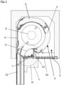
- Reference numeral 1 designates a window frame, above which a building-side installation space 2 in the form of a roller shutter shaft is located.
- a renovation roller shutter, designated 3 overall, is installed in the installation space 2.
- This renovation roller shutter is designed as a top-mounted roller shutter with a baseboard profile 7 mounted on the window frame 1. This situation is particularly common in older buildings that already have roller shutter shafts above the windows and where the thermal insulation value of the facade is to be increased as part of the window replacement or even just by replacing the roller shutters.
- the renovation roller shutter 3 has a winding shaft housing consisting of insulation elements 4, 5 and a front cover 6 on the building's exterior, as well as an insulation layer 9 on the floorboard profile 7, so that the building's interior is completely insulated from a curtain outlet opening located above a guide rail 11 and thus from the building's exterior.
- Reference 8 indicates the winding shaft of the renovation roller shutter, which can be rotated on front side panels (not shown in detail). is mounted, wherein the side parts are attached to the front side of the floor board profile 7, preferably in a hinged manner, as is the case, for example, in the own application DE 10 2009 052 010 A1 which is fully included here in this regard.
- the baseboard of the top-mounted roller shutter is formed by individual elements, namely the baseboard profile 7, which is to be attached to the window frame 1 and, in this case, is to be screwed, and a baseboard mounting profile 12 that supports the insulation support 9 of the baseboard.
- the baseboard profile 7, preferably with foldable side parts attached to it to support the winding shaft 8 can be inserted into the installation space 2 and fastened to the window frame 1.
- the upper insulation crescent 5 can then be pushed into position along guides provided on the side parts, whereupon the winding shaft 8 with the curtain mounted on it can be mounted between the side parts.
- the baseboard mounting profile, together with the insulation support 9, is then mounted on the baseboard profile 7, whereupon the lower insulation crescent 4 can be inserted and hooked onto the back of the baseboard mounting profile 12.
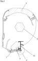
- Fig. 2 shows the assembly state in which the upper insulation crescent 5 is already in Position above the winding shaft 8 and the insulation layer 9 is mounted on the floor board profile 7 using the floor board mounting profile 12.
- Fig. 3 shows an earlier assembly step in which the floorboard mounting profile with the insulation support 9 is only attached to the floorboard profile 7, but is not yet completely mounted on the floorboard profile 7.
- Fig. 3 shows a mounting position of the floor board mounting profile, Fig. 2 an installation position.
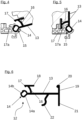
- a longitudinal groove 15 can be seen on the floorboard profile 7, which has a circular cross-section and an opening extending approximately over a quarter circle.
- the floorboard mounting profile 12, on the other hand, has a base body 13, from whose narrow side facing the floorboard profile 7 protrudes a spring head 14 with a circular cross-section and two opposing flats 14a, 14b.
- the flats 14a, b are in the Fig. 6 designated.
- the floor board mounting profile is inserted into the longitudinal groove 15 of the floor board profile, which corresponds to the Fig. 4 shown mounting position with almost horizontal base body 13 of the floor board mounting profile and then into the Fig. 5 shown installation position with almost vertical base body 13, in which then also the insulation layer as in Fig. 1 shown rests on the floor board profile 7 and is mounted there, as described in detail in Fig. 9 is shown.
- the floorboard mounting profile 12 has a fastening web 16 protruding from the broad side of the base body 13 facing the insulation layer, which carries a locking lug or locking lug strip 17 on its side facing the floorboard profile 7.
- This locking lug 17 is assigned a counter-locking lug 17a of the floorboard profile 7, which is attached to the outer circumference of the longitudinal groove, behind which the locking lug 17 is engaged when the installation position of the floorboard mounting profile is reached. clicks into place.
- the floor board mounting profile 12 has on the broad side, on which the fastening web 16 projects, a further, projecting fastening web 19, wherein the fastening webs 16, 19 carry fastening projections 18, 20 facing one another.
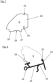
- the insulation support 9 shown in detail has a fastening section 23 which connects to the rest of the insulation support 9 via two undercuts 24, 25.
- the insulation layer 9 can then be inserted with its fastening section 23 between the two fastening webs 16, 19 and clipped or snapped on there by means of the two fastening projections 18, 20 and the associated undercuts 24, 25.
- two further webs 21, 22 are provided, which project there and form a receptacle for the lower end of the lower insulation element 4, which can be inserted there after mounting the floorboard mounting profile 12 with the insulation element 9 on the floorboard profile 7, as shown in the Fig. 1 can be seen.
- Fig. 9 shows the installation position of the floor board mounting profile 12 on the floor board profile 7. There you can see two projections 26, 27 protruding from the underside of the insulation support 9, which have been pushed between two webs 30, 31 projecting upwards from the floor board profile 7, preferably by clamping.
- a recess 28 is provided between the two projections 26, 27 of the insulation support 9, which prevents the insulation support 9 from coming to rest on screw heads (not shown) with which the floor board profile 7 is fastened to the window frame 1.
- FIG. 10-12 relate to an alternative embodiment of the renovation roller shutter shown in the previous figures, in which an insect screen roller blind 39 is to be attached to the floor board profile 7 instead of an insulating layer 9.
- the insect screen roller blind 39 has a housing 40, which rotatably accommodates a winding shaft with a blind barrel 41 and from which the blind 42 extends downwards through a blind outlet opening.
- a bottom strip 46 hangs from the lower end of the blind 42.
- a fastening section 43 protrudes from the housing 40 on a side facing the floorboard mounting profile 12. This fastening section 43 connects to the housing 40 via two undercuts 44, 45, with which the insect screen roller blind 39 can be clipped onto the fastening projections 18, 20 of the floorboard mounting profile 12.
- the winding shaft 8 could have an extendable axle pin to simplify assembly between the two side parts erected in the installation space 2.
- an extendable axle pin is, for example, the subject of the company's own European patent EP 1 746 244 B1 , of its own European patent EP 3 611 328 B1 and EP 3 611 329 B1 , which are fully included here in this regard.
Landscapes
- Engineering & Computer Science (AREA)
- Structural Engineering (AREA)
- Architecture (AREA)
- Civil Engineering (AREA)
- Specific Sealing Or Ventilating Devices For Doors And Windows (AREA)
- Operating, Guiding And Securing Of Roll- Type Closing Members (AREA)
Description
- Die Erfindung betrifft gemäß Anspruch 14 einen Aufsatzrollladen zum Einbau in einen gebäudeseitigen Einbauraum oberhalb eines Fensters, einer Türe oder dergleichen, welcher ein auf einem Fenster- oder Türrahmen oder dergleichen montiertes Bodenbrett aufweist. Die Erfindung betrifft ferner gemäß Anspruch 8 ein für einen Aufsatzrollladen geeignetes Bodenbrett und gemäß Anspruch 1 ein Bodenbrett-Montageprofil zur Montage einer Dämmauflage und/oder eines Zusatzfunktionselements wie beispielsweise eines Insektenschutzrollos an einem auf einem Fenster- oder Türrahmen oder dergleichen montierten Bodenbrettprofil eines Aufsatzrollladens.
- Aufsatzrollläden werden, wie der Name sagt, aufgesetzt, und zwar oben auf einen Fenster- oder Türrahmen oder dergleichen. Dazu weisen Aufsatzrollläden im Allgemeinen ein Bodenbrett auf, mit welchem sie an dem Fenster- oder Türrahmen befestigt sind. Das Bodenbrett ist mit zwei stirnseitigen Seitenteilen verbunden, die eine sich längs des Bodenbretts erstreckende Wickelwelle für einen Rollladenbehang aufnehmen. Die Erfindung betrifft dabei besonders einen Aufsatzrollladen, bei dem gebäudeaußenseitig des Bodenbretts, also des Fensters bzw. der Türe oder dergleichen die Ebene vorgesehen ist, in der ein Rollladenbehang vor dem Fenster auf- bzw. abgelassen werden soll, wohingegen eine Revisionsöffnung, durch die hindurch der Aufsatzrollladen zu Revisionszwecken zugänglich sein soll, sich auf der Gebäudeinnenseite des Bodenbretts, also des Fensters bzw. der Türe befindet. Ein solcher, gattungsgemäßer Aufsatzrollladen ist in der deutschen Gebrauchsmusterschrift
DE 20 2007 017 443 U1 gezeigt. - Derartige Aufsatzrollläden werden häufig zu Renovierungszwecken in gebäudeseits bereits vorhandene Einbauräume eingebaut und ersetzen die dort ursprünglich bereits vorhandenen Rollläden. Bei der Ausrüstung solcher gebäudeseits bereits vorgesehenen Einbauräume mit Aufsatzrollläden wird heutzutage im Sinne der gesetzlich vorgeschriebenen Wärmedämmung der Gebäudehülle höchster Wert auf eine Dämmung des mit der Gebäudeumgebung über eine Behangauslassöffnung verbundenen Einbauraums gegenüber dem Gebäudeinneren gelegt. Dazu gehört auch eine Wärmedämmung des Bodenbretts selbst mittels einer auf dem Bodenbrett vorgesehenen Dämmauflage, wie bereits die
DE 20 2007 017 443 U1 zeigt. - Andererseits wurde auch bereits versucht, das Bodenbrett des Aufsatzrollladenkastens dafür zu nutzen, daran ein Zusatzfunktionselement wie beispielsweise ein Insektenschutzrollo anzubringen. Ein Beispiel hierfür zeigt die europäische Patentanmeldung
EP 0 737 796 A2 . Diese Lösung benötigt allerdings erheblich Bauraum zwischen der Behangebene und dem Fenster, welcher in vielen Fällen nicht vorhanden ist. Ähnliches gilt für die in der europäischen PatentanmeldungEP 2 348 187 A2 vorgeschlagene Lösung, bei der ebenfalls eine Zusatzrolle am Bodenbrett eingehängt ist, sich allerdings oberhalb des Bodenbretts befindet und bei der Montage in beengten Verhältnissen Schwierigkeiten machen dürfte. - Es ist daher Aufgabe der vorliegenden Erfindung, bei einem Aufsatzrollladen die Dämmung des Bodenbretts und/oder das Anbringen von Funktionselementen wie beispielsweise ein Insektenschutzrollo an dem Bodenbrett zu vereinfachen.
- Diese Aufgabe wird hinsichtlich des Aufsatzrollladens mit den Merkmalen des Anspruchs 14 gelöst, hinsichtlich des Bodenbretts mit den Merkmalen des Anspruchs 8, und zwar mithilfe eines Bodenbrett-Montageprofils, welches Gegenstand des Anspruchs 1 ist.
- Erfindungsgemäß wird ein Bodenbrett-Montageprofil zur Montage einer Dämmauflage und/oder eines Zusatzfunktionselements wie beispielsweise einem Insektenschutzrollo an einem auf einem Fenster- oder Türrahmen oder dergleichen montierten Bodenbrettprofil eines Aufsatzrollladens vorgeschlagen, welches sich dadurch auszeichnet, dass das Bodenbrett-Montageprofil dazu geeignet ist, an einer Schmalseite des Bodenbrettprofils gelenkig angebracht und aus einer Anbringstellung in eine am Bodenbrettprofil montierte Einbaustellung verschwenkt zu werden, sowie dadurch, dass es eine Dämmauflage und/oder ein Zusatzfunktionselement wie beispielsweise ein Insektenschutzrollo trägt.
- Weiterhin erfindungsgemäß wird ein Bodenbrett für einen Aufsatzrollladen vorgeschlagen, welches ein zur Montage auf einem Fenster- oder Türrahmen oder dergleichen vorgesehenes Bodenbrettprofil aufweist, an dem eine Dämmauflage und/oder ein Zusatzfunktionselement wie beispielsweise ein Insektenschutzrollo angebracht ist. Das Bodenbrettprofil hat dabei eine in seinem montierten Zustand nach gebäudeaußen weisende, erste Schmalseite und eine nach gebäudeinnen weisende, zweite Schmalseite und zeichnet sich dadurch aus, dass an der zweiten Schmalseite des Bodenbrettprofils das erfindungsgemäße Bodenbrett-Montageprofil angelenkt ist, welches die Dämmauflage und/oder das Zusatzfunktionselement, insbesondere das Insektenschutzrollo trägt.
- Weiterhin erfindungsgemäß wird eine Aufsatzrollladen zum Einbau in einen gebäudeseitigen Einbauraum oberhalb eines Fensters, einer Türe oder dergleichen vorgeschlagen, welcher ein auf einem Fenster- oder Türrahmen oder dergleichen montiertes Bodenbrett aufweist, auf dem zwei stirnseitige Seitenteile befestigt sind, die eine sich längs des Bodenbretts erstreckende Wickelwelle für einen Rollladenbehang drehbar aufnehmen. Dabei sind gebäudeaußenseitig des Bodenbretts sich von einer Behangauslassöffnung nach unten erstreckende Behangführungsschienen und gebäudeinnenseitig des Bodenbretts ein Deckel zum Verschluss einer Revisionsöffnung vorgesehen. Der Aufsatzrollladen zeichnet sich dabei durch ein erfindungsgemäßes Bodenbrett aus.
- Dadurch, dass ein an dem Bodenbrett gelenkig anbringbares Bodenbrett-Montageprofil vorhanden ist, welches die Dämmauflage für das Bodenbrett und/oder ein am Bodenbrett anzubringendes Zusatzfunktionselement wie beispielsweise einen Insektenschutzrollo trägt, gelingt eine relativ einfache Montage der Dämmauflage bzw. des Zusatzfunktionselements auf dem Bodenbrett in beengtem Einbauraum oberhalb des Fensters oder der Türe. Dies ist insbesondere ausschlaggebend für das Gelingen einer Montage von Nachrüst- bzw. Renovierungssystem in bei Altbauten gebäudeseitig bereits vorhandenen Rollladenschächten oberhalb des Fensters, wenn mit dem Rollladen nicht gleichzeitig auch das Fenster ausgetauscht werden soll. Denn in diesem Fall lässt sich zunächst das Bodenbrettprofil auf dem Fenster- bzw. Türrahmen anbringen, dann das Bodenbrett-Montageprofil an dem Bodenbrettprofil anlenken und anschließend aus dieser Anbringstellung in eine montierte Einbaustellung verschwenken. Da das Bodenbrett-Montageprofil die Bodenbrett-Dämmauflage bzw. das auf dem Bodenbrett zu montierende Zusatzfunktionselement trägt, gelingt die Montage der Dämmauflage bzw. des Zusatzfunktionselements auf die vorstehend beschriebene, einfache Weise, die somit zum Gegenstand eines eigenständigen Verfahrensanspruchs gemacht werden könnte.
- Hierbei handelt es sich um eine insbesondere für Renovierungsrollläden im Altbaubereich besonders vorteilhafte Lösung, weil dort die Revisionsöffnung, über die der Einbauraum für den Rollladen, also der Rollladenschacht oberhalb des Fensters, zugänglich, ist im Allgemeinen auf der Gebäudeinnenseite, meist an der nach unten weisenden Fensterlaibung befindet, durch die hindurch die Montage des Renovierungsrollladens und damit des Bodenbretts auf dem Fenster- bzw. Türrahmen oder dergleichen erfolgen muss. Voluminöse und schwere Bauteile, wie beispielsweise ein bereits vollständig mit einem Insektenschutzrollo vormontiertes Bodenbrett unter diesen Umständen zu montieren kann schwierig und kraftraubend sein und wird durch die vorgeschlagene Lösung wesentlich erleichtert, weil ja zunächst das Bodenbrett am Rahmen montiert wird und dann erst die Dämmauflage bzw. das Zusatzfunktionselement mithilfe des Bodenbrett-Montageprofils durch die Revisionsöffnung in den Einbauraum eingebracht wird und an dem Bodenbrettgrundprofil angelenkt wird, um durch Verschwenken in die Endlage, nämlich die montierte Einbaustellung, gebracht zu werden.
- Vorteilhafte Weiterbildungen sind Gegenstand der Unteransprüche.
- So weist das Bodenbrett-Montageprofil vorteilhaft einen insbesondere als flaches Brettelement ausgeformten Grundkörper auf, an dessen in Anbringstellung dem Bodenbrett zugewandten Schmalseite ein Federkopf angebracht ist, der zum Einstecken in eine Längsnut des Bodenbretts und zum Verschwenken des Bodenbrett-Montageprofils in der Längsnut geeignet ist, um so ein Scharnier zum Verschwenken des Bodenbrett-Montageprofils zu bilden.
- Dementsprechend weist das Bodenbrettprofil insbesondere an seiner nach gebäudeinnen weisenden, zweiten Schmalseite die einseitig offene Längsnut auf, so dass das Scharnier zum Verschwenken des Bodenbrett-Montageprofils aus der Anbringstellung in die Einbaustellung mittels Längsnut am Bodenbrettprofil und Federkopf am Bodenbrett-Montageprofil gebildet werden kann. Selbstverständlich wäre auch eine Umkehrung denkbar, also Federkopf am Bodenbrettprofil und Längsnut am Bodenbrett-Montageprofil.
- Nach Montage des Bodenbrettprofils auf dem Fenster- bzw. Türrahmen lässt sich das Bodenbrett-Montageprofil dann mit seinem Federkopf an der Längsnut des Bodenbrettprofils ansetzen. Nach Einstecken des Federkopfs in die Längsnut, im Allgemeinen frontal von vorne und nicht von der Seite her, weil dort kein Platz dafür vorhanden ist, kann dann das Bodenbrett-Montageprofil mit der Dämmauflage bzw. dem Zusatzfunktionselement in die Einbaustellung verschwenkt werden.
- Weiterhin vorteilhaft weist der Federkopf des Bodenbrett-Montageprofils einen im Wesentlichen kreisrunden Querschnitt auf, der an zwei gegenüberliegenden Seiten zwei parallele Abflachungen hat. Die zugeordnete Längsnut des Bodenbrettprofils kann dann über einen Winkelbereich geöffnet sein, das das Einstecken des Bodenbrett-Montageprofils bzw. seines Federkopfs in Richtung entlang der parallelen Abflachungen erlaubt, aber in der verschwenkten Einbaustellung, in der die parallelen Abflachungen gegenüber der Öffnung der Längsnut verdreht sind, eine Entnahme oder ein unbeabsichtigtes Lösen des Bodenbrett-Montageprofils vom Bodenbrettprofil verhindert. Die Kombination aus der in einem bestimmten Winkelbereich geöffneten Längsnut und der Gestaltung des Federkopfs mit im Wesentlichen kreisrunden Querschnitt, der auf gegenüberliegenden Seiten abgeflacht ist, bildet somit eine Art Schloss. Dabei ist es natürlich ebenfalls vorteilhaft, wenn die Längsnut des Bodenbrettprofils auch einen im Wesentlichen kreisrunden Querschnitt aufweist, sodass sich der Federkopf auf einfach Weise in dem komplementären, ebenfalls kreisrunden Querschnitt der Längsnut verdrehen lässt.
- Zur Befestigung der Dämmauflage bzw. des Zusatzfunktionselements an dem Bodenbrett-Montageprofil werden zwei Einfassungsstege vorgeschlagen, die von einer ersten Breitseite des Grundkörpers des Bodenbrett-Montageprofils vorstehen, wobei die Dämmauflage und/oder das Zusatzfunktionselement dann einen Befestigungsabschnitt aufweisen kann, der an dem Grundkörper anliegt und von den beiden Einfassungsstegen eingefasst ist. Die Befestigung kann dann per Klemmung oder Verklebung erfolgen, bevorzugt ist es jedoch, wenn die beiden Einfassungsstege jeweils mit einem Befestigungsvorsprung versehen sind, wobei die beiden Befestigungsvorsprünge einander zugewandt sind und der Befestigungsabschnitt der Dämmauflage bzw. des Zusatzfunktionselements zwei den Befestigungsvorsprüngen zugewandte Hinterschneidungen hat, sodass die Dämmauflage bzw. das Zusatzfunktionselement auf das Bodenbrett-Montageprofil aufgerastet bzw. klippsverbunden werden kann.
- Auf der gegenüberliegenden, zweiten Breitseite des Grundkörpers des Bodenbrett-Montageprofils kann dann eine Wickelwelleneinhausungsaufnahme ausgeformt sein, bspw. ebenfalls in Form von zwei dort vorspringenden Stegen, in die ein Ende einer Wickelwelleneinhausung des Aufsatzrollladens aufgenommen werden kann. Denkbar wäre aber auch ein einzelner Steg, der von der zweiten Breitseite des Grundkörpers des Bodenbrett-Montageprofils vorsteht, auf den dann das Ende der Wickelwelleneinhausung mit einer entsprechenden Ausnehmungaufgesteckt werden kann, z.B. dann, wenn die Wickelwelleneinhausung ein Dämmelement aufweist, in dessen Dämmstoffschicht eine solche Ausnehmung vorgesehen sein kann.
- Der Aufsatzrollladen weist im Allgemeinen eine die Wickelwelle mit dem Behang mehrseitig umschließende Wickelwelleneinhausung auf, die gerade bei Renovierungsrollläden vorteilhaft aus hohlzylindersegmentförmigen Dämmstoffelementen, sogenannten Dämmsicheln besteht, die an den die Wickelwelle tragenden Seitenteilen befestigt, vorteilhaft in dort vorgesehene Führungen durch die Revisionsöffnung hindurch eingeschoben sind. Das gebäudeinnenseitig dem Bodenbrett zugewandte Ende der Wickelwelleneinhausung wird dann von einer solchen, dort vorgesehenen Dämmsichel, bspw. bestehend aus Styropor oder ähnlichen Dämmstoffen, gebildet und kann in die Wickelwelleneinhausungsaufnahme des Bodenbrett-Montageprofils eingesteckt werden.
- Dazu ist es vorteilhaft, wenn der Grundkörper in der Einbaustellung des Bodenbrett-Montageprofils nach oben ragt, sodass die Wickelwelleneinhausungsaufnahme zur Gebäudeinnenseite hin weist und die Einfassungsstege für den Befestigungsabschnitt der Dämmauflage bzw. des Zusatzfunktionselements zur Gebäudeaußenseite, also zum Bodenbrettprofil hin. Vorteilhaft sind das von der Längsnut des Bodenbrettprofils und dem Federkopf des Bodenbrett-Montageprofils gebildete Scharnier und die Dämmauflage bzw. das Zusatzfunktionselement dabei so gestaltet, dass der Grundkörper in der Einbaustellung vertikal oder nahezu vertikal nach oben weist. Es kommt dabei nicht auf große Genauigkeit an. Nahezu vertikal nach oben kann in diesem Zusammenhang auch eine Winkelabwichtung von +/- 25 Grad bedeuten.
- Weiterhin vorteilhaft im Sinne einer einfachen Montage ist es dabei, wenn sich das Bodenbrett-Zusatzprofil mit horizontalem oder gegenüber der Horizontalen leicht geneigtem Grundkörper an das Bodenbrett ansetzen und mit seinem Federkopf in die zugeordnete Längsnut des Bodenbretts einführen lässt. Diese horizontale oder gegenüber der Horizontalen leicht geneigte Stellung entspricht somit der Anbringstellung, wobei es hier ebenfalls nicht auf große Genauigkeit ankommt, sodass die leicht geneigte Stellung ebenfalls eine Abweichung von +/- 25 Grad zur Horizontalen aufweisen kann.
- Hierzu ist die Längsnut des Bodenbrettprofils über einen solchen Winkelbereich geöffnet und der Federkopf über einen solchen Federhals an dem Grundkörper des Bodenbrett-Montageprofils angebracht, dass sich das Bodenbrett-Montageprofil horizontal oder leicht geneigt an das Bodenbrettprofil ansetzen und aus diesen Anbringstellung in die vertikale oder nahezu vertikale Stellung des Grundkörpers, die der Einbaustellung des Bodenbrett-Montageprofils entspricht, verschwenken lässt.
- Besonders bevorzugt ist dabei aber auch, wenn die Öffnung der Längsnut des Bodenbrettprofils und der Federhals am Grundkörper des Bodenbrett-Montageprofils das Verschwenken aus dieser horizontalen oder leicht geneigten Anbringstellung in die vertikale oder nahezu vertikale Einbaustellung nicht nur erlaubt, sondern das Verschwenkung auch auf diesen Bereich begrenzt. Wenn also die Ränder der Öffnung der Längsnut auf beiden Seiten einen Anschlag für den Federhals des Bodenbrett-Montageprofils bilden. Der Anschlag, an den der Federhals bei Erreichen der vertikalen oder nahezu vertikalen Stellung des Grundkörpers anschlägt, signalisiert so das Erreichen der Einbaustellung. Der gegenüberliegende Anschlag an dem der Federhals bei in der Anbringstellung in die Längsnut eingeschobenen Federkopf anschlägt, kann dagegen in Zusammenspiel mit der gegenüberliegenden Wandung der Längsnut als montageunterstützende Halterung zum Halten des mit dem Federkopf in die Längsnut eingesetzten Bodenbrett-Montageprofils dienen.
- Im Sinne einer zusätzlichen Signalisierung des Erreichens der Einbaustellung beim Verschwenken des Bodenbrett-Montageprofils und/oder im Sinne einer zusätzlichen Befestigung des Bodenbrett-Montageprofils an dem Bodenbrettprofil in der Einbaustellung kann zudem eine zusätzliche Verrastung zwischen Bodenbrett-Montageprofil und Bodenbrettprofil vorgesehen sein die - vorteilhaft hörbar - einrastet, wenn das Bodenbrett-Montageprofil die Einbaustellung erreicht.
- Dazu kann das Bodenbrett-Montageprofil einen von seinem Grundkörper vorstehenden Steg aufweisen, der in der Einbaustellung der Oberseite des Bodenbrettprofils zugewandt ist und einen Rastkopf trägt. Das Bodenbrettprofil kann einen dem Rastkopf zugeordneten Gegenrastkopf aufweisen, wobei Rastkopf und Gegenrastkopf, die ja jeweils an einem Profil ausgebildet sind, vorteilhaft als Rastkopfleiste bzw. Gegenrastkopfleiste ausgebildet sind und so, dass sie sich zum Verrasten bei Erreichen der Einbaustellung des Bodenbrett-Montageprofils beim Verschwenken des Bodenbrett-Montageprofils aus seiner Anbringstellung in seine Einbaustellung eignen.
- Dabei ist es bei einer Weiterbildung des Bodenbrett-Montageprofils mit den beiden Einfassungsstegen für den Befestigungsabschnitt der Dämmauflage bzw. des Zusatzfunktionselements besonders günstig, wenn der auf der dem Federkopf zugewandten Seite angeordnete, vom Grundkörper vorstehende Einfassungssteg auf der seinem Befestigungsvorsprung für die Dämmauflage bzw. für das Funktionselement abgewandten Seite den Rastkopf aufweist, mit dem das Bodenbrett-Montageprofil beim Erreichen der Einbaustellung am zugeordneten Gegenrastkopf des Bodenbrettprofils eingerastet wird.
- Die Dämmauflage und/oder das Zusatzfunktionselement weist vorteilhaft eine dem Grundkörper des Bodenbrett-Montageprofils zugewandte Seite auf und eine demgegenüber in etwa um einen Viertelkreis, je nach Stellung des Grundkörpers in der Einbaustellung gegenüber der Oberseite des Bodenbrettprofils versetzte Unterseite. An der Unterseite kann ein Klemm- und/oder Aufrastabschnitt vorgesehen sein, der beim Verschwenken des Bodenbrett-Montageprofils aus der Anbringstellung in die Einbaustellung zwischen zwei vom Bodenbrettprofil nach oben vorspringende Klemm- und/oder Raststege aufgenommen werden kann.
- Nachfolgend werden anhand der beiliegenden Figuren bevorzugte Ausführungsformen der Erfindung näher erläutert. Es zeigen:
-
Fig. 1 eine Querschnittansicht durch einen Renovierungsrollladen gemäß einer ersten Ausführungsform der Erfindung im in einem gebäudeseitigen Einbauraum eingebauten Zustand; -
Fig. 2 eine perspektivisch derFig. 1 entsprechende Ansicht des Renovierungsrollladens während des Einbaus; -
Fig. 3 eine derFig. 2 entsprechende Ansicht des Renovierungsrollladens während eines vorgeordneten Montageschritts; -
Fig. 4 Einzelheit IV inFig. 3 ; -
Fig. 5 Einzelheit V inFig. 2 ; -
Fig. 6 ein Bodenbrett-Montageprofil für den inFig. 1-5 gezeigten Renovierungsrollladen im Detail; -
Fig. 7 eine Bodenbrett-Dämmauflage für den in denFig. 1-5 gezeigten Renovierungsrollladen im Detail; -
Fig. 8 die inFig. 7 gezeigte Bodenbrett-Dämmauflage im an den Bodenbrett-Montageprofil derFig. 6 montierten Zustand; -
Fig. 9 Einzelheit IX ausFig. 1 ; -
Fig. 10 ein auf das in derFig. 6 gezeigt Bodenbrett-Montageprofil passendes Insektenschutzrollo; -
Fig. 11 ein mit dem inFig. 10 gezeigten Insektenschutzrollo ausgestattetes Bodenbrett eines Aufsatzrollladens gemäß einer weiteren Ausführungsform der Erfindung; und -
Fig. 12 das inFig. 11 gezeigte Bodenbrett in montierter Einbaustellung des Bodenbrett-Montageprofils. - Zunächst wird Bezug genommen auf die
Fig. 1 . - Mit Bezugsziffer 1 ist dabei ein Fensterrahmen bezeichnet, oberhalb dem ein gebäudeseitiger Einbauraum 2 in Form eines Rollladenschachts vorhanden ist. In den Einbauraum 2 ist dabei ein insgesamt mit 3 bezeichneter Renovierungsrollladen eingebaut, welcher als Aufsatzrollladen ausgebildet ist mit einem Bodenbrettprofil 7 auf dem Fensterrahmen 1 montiert ist. Diese Situation ist besonders bei Altbauten häufig, an denen oberhalb der Fenster bereits Rollladenschächte bereits vorhanden sind und bei denen im Zuge des Fenstertausches oder auch nur durch Austausch der Rollläden der Wärmedämmwert der Fassade erhöht werden soll.
- Hierzu weist der Renovierungsrollladen 3 eine aus Dämmelementen 4, 5 und einer gebäudeaußenseitigen Frontabdeckung 6 bestehende Wickelwelleneinhausung auf, sowie eine Dämmauflage 9 auf dem Bodenbrettprofil 7, sodass die Gebäudeinnenseite gegenüber einer sich oberhalb einer Führungsschiene 11 befindenden Behangauslassöffnung und damit der Gebäudeaußenseite vollständig gedämmt ist. Mit 8 ist hier die Wickelwelle des Renovierungsrollladens angedeutet, die auf nicht näher dargestellten, stirnseitigen Seitenteilen drehbar gelagert ist, wobei die Seitenteile stirnseitig an dem Bodenbrettprofil 7 vorzugsweise aufklappbar befestigt sind, wie dies beispielsweise in der eigenen Anmeldung
DE 10 2009 052 010 A1 hervorgeht, die diesbezüglich hier vollumfänglich miteinbezogen wird. - Gebäudeinnenseitig ist dabei an der nach unten weisenden Laibungswand eine Revisionsöffnung vorhanden, die mit einem Deckel 10 verschlossen ist und über die der Einbauraum 2 zugänglich ist. Durch diese Revisionsöffnung hindurch muss also zumindest in dem Fall, dass das Fenster nicht mit ausgetauscht werden soll, die Montage des Renovierungsrollladens 3 erfolgen. Der Renovierungsrollladen 3 kann also nicht am Stück eingebaut werden, sondern in einzelnen Modulen, die dann im beengten Einbauraum auf möglichst einfach Weise miteinander verbunden werden müssen.
- In diesem Sinne ist nicht nur die Wickelwelleneinhausung von einzelnen Dämmelementen bzw. Dämmsicheln 4, 5 gebildet, sondern auch das Bodenbrett des Aufsatzrollladens von einzelnen Elementen, nämlich dem am Fensterrahmen 1 zu befestigenden, im vorliegenden Fall zu verschraubenden Bodenbrettprofils 7 und einem die Dämmauflage 9 des Bodenbretts tragenden Bodenbrett-Montageprofil 12. Zunächst kann also das Bodenbrettprofil 7, bevorzugt mit daran klappbar befestigten Seitenteilen zur Abstützung der Wickelwelle 8 in den Einbauraum 2 eingebracht und am Fensterrahmen 1 befestigt werden. Nach Aufklappen der Seitenteile kann dann die obere Dämmsichel 5 entlang von an den Seitenteilen vorgesehenen Führungen in Position geschoben werden, woraufhin die Wickelwelle 8 mit dem darauf aufgenommenen Behang zwischen die Seitenteile montiert werden kann. Anschließend wird dann das Bodenbrett-Montageprofil mit samt der Dämmauflage 9 auf dem Bodenbrettprofil 7 montiert, woraufhin die untere Dämmsichel 4 eingesetzt und rückseitig am Bodenbrett-Montageprofil 12 eingehängt werden kann. Nach Schließen des Revisionsdeckels 10 und Anbringen der gebäudeaußenseitigen Führungsschienen 11 für den auf der Wickelwelle 8 aufgenommenen Behang ist die Montage abgeschlossen.
-
Fig. 2 zeigt dabei den Montagezustand, in dem die obere Dämmsichel 5 bereits in Position oberhalb der Wickelwelle 8 eingeschoben ist und die Dämmauflage 9 mithilfe des Bodenbretts-Montageprofils 12 auf dem Bodenbrettprofil 7 montiert ist. -
Fig. 3 zeigt dagegen einen Montageschritt zuvor, in dem das Bodenbrett-Montageprofil mit der Dämmauflage 9 erst am Bodenbrettprofil 7 angesetzt, aber noch nicht vollständig am Bodenbrettprofil 7 montiert ist.Fig. 3 zeigt also eine Anbringstellung des Bodenbrett-Montageprofils,Fig. 2 eine Einbaustellung. - Dabei sind die Einzelheiten der scharniergelenkigen Verbindung von Bodenbrett-Montageprofil 12 und Bodenbrettprofil 7 der
Fig. 4 in der Anbringstellung und derFig. 5 in der Einbaustellung zu entnehmen. - Man erkennt eine Längsnut 15 am Bodenbrettprofil 7, welche einen kreisrunden Querschnitt aufweist und einen sich in etwa über einen Viertelkreis erstreckenden Öffnungsbereich. Das Bodenbrett-Montageprofil 12 hat dagegen einen Grundkörper 13, von dessen dem Bodenbrettprofil 7 zugewandter Schmalseite ein Federkopf 14 mit einem kreisrunden Querschnitt und zwei gegenüberliegenden Abflachungen 14a, 14b vorspringt. Die Abflachungen 14a, b sind in der
Fig. 6 bezeichnet. - Mit diesem Federkopf 14 wird das Bodenbrett-Montageprofil in die Längsnut 15 des Bodenbrettprofils eingeführt, was der in
Fig. 4 gezeigten Anbringstellung mit nahezu horizontalem Grundkörper 13 des Bodenbrett-Montageprofils entspricht und dann in die inFig. 5 gezeigte Einbaustellung mit nahezu vertikalem Grundkörper 13 verschwenkt, in der dann auch die Dämmauflage wie inFig. 1 gezeigt auf dem Bodenbrettprofil 7 aufliegt und dort montiert ist, wie im Einzelnen auch inFig. 9 gezeigt ist. - Das Bodenbrett-Montageprofil 12 weist dabei einen von der der Dämmauflage zugewandten Breitseite des Grundkörpers 13 vorstehenden Befestigungssteg 16 auf, welcher auf seiner dem Bodenbrettprofil 7 zugewandten Seite eine Rastnase bzw. Rastnasenleiste 17 trägt. Dieser Rastnase 17 ist eine am Außenumfang der Längsnut angebrachte Gegenrastnase 17a des Bodenbrettprofils 7 zugeordnet, hinter welcher die Rastnase 17 bei Erreichen der Einbaustellung des Bodenbrett-Montageprofils einrastet.
- Wie
Fig. 6 zeigt, weist das Bodenbrett-Montageprofil 12 auf der Breitseite, an dem der Befestigungssteg 16 vorspringt, einen weiteren, vorspringenden Befestigungssteg 19 auf, wobei die Befestigungsstege 16, 19 einander zugewandte Befestigungsvorsprünge 18, 20 tragen. - Die in
Fig. 7 im Einzelnen gezeigte Dämmauflage 9 hat dagegen einen Befestigungsabschnitt 23, der über zwei Hinterschneidungen 24, 25 an dem Rest der Dämmauflage 9 anschließt. WieFig. 8 zeigt, kann die Dämmauflage 9 dann mit ihrem Befestigungsabschnitt 23 zwischen die beiden Befestigungsstege 16, 19 gesteckt werden und dort mittels der beiden Befestigungsvorsprünge 18, 20 und den zugeordneten Hinterschneidungen 24, 25 aufgeklipst bzw. aufgerastet werden. - Auf der der Breitseite des Grundkörpers 13 mit den Befestigungsstegen 16, 19 gegenüberliegenden Breitseite sind zwei weitere, dort vorspringende Stege 21, 22 vorgesehen, die eine Aufnahme für das untere Ende des unteren Dämmelements 4 bilden, welches dort nach Montage des Bodenbrett-Montageprofils 12 mit dem Dämmelement 9 an dem Bodenbrettprofil 7 eingeschoben werden kann, wie in der
Fig. 1 zu entnehmen ist. -
Fig. 9 zeigt die Einbaustellung des Bodenbrett-Montageprofils 12 am Bodenbrettprofil 7. Man erkennt dort zwei unterseitig an der Dämmauflage 9 abstehende Vorsprünge 26, 27, die zwischen zwei vom Bodenbrettprofil 7 nach oben vorstehende Stege 30, 31, geschoben worden sind, vorzugsweise unter Klemmung. - Zwischen den beiden Vorsprüngen 26, 27 der Dämmauflage 9 ist dabei eine Ausnehmung 28 vorgesehen, die verhindert, dass die Dämmauflage 9 auf (nicht gezeigten) Schraubenköpfen zur Auflage kommt, mit denen das Bodenbrettprofil 7 am Fensterrahmen 1 befestigt ist.
- Die weiteren
Fig. 10-12 betreffen eine alternative Ausführungsform des in den vorherigen Figuren gezeigten Renovierungsrollladens, bei der anstatt einer Dämmauflage 9 ein Insektenschutzrollo 39 auf dem Bodenbrettprofil 7 befestigt werden soll. - Es wäre aber auch denkbar, über einen Teil der Fensterbreite eine Dämmauflage 9 und über einen weiteren Teil der Fensterbreite ein Insektenschutzrollo 39 vorzusehen.
- Das Insektenschutzrollo 39 weist dabei ein Gehäuse 40 auf, welches eine Wickelwelle mit einem Behangballen 41 drehbar aufnimmt und aus dem der Behang 42 an einer Behangauslassöffnung nach unten herausgeführt ist. Am unteren Ende des Behangs 42 hängt dabei eine Endleiste 46. Vom Gehäuse 40 steht dabei auf einer dem Bodenbrett-Montageprofil 12 zugewandten Seite wiederum ein Befestigungsabschnitt 43 ab, der über zwei Hinterschneidungen 44, 45 an dem Gehäuse 40 anschließt, mit welchen das Insektenschutzrollo 39 an den Befestigungsvorsprüngen 18, 20 des Bodenbrett-Montageprofils 12 aufgeklipst werden kann.
- Abwandlungen und Modifikationen der gezeigten Ausführungsformen sind möglich, ohne den Rahmen der Erfindung zu verlassen.
- So könnte die Wickelwelle 8 beispielsweise über einen ausschiebbaren Achsbolzen verfügen, um die Montage zwischen den beiden im Einbauraum 2 aufgerichteten Seitenteilen zu vereinfachen. Ein solcher ausschiebbarer Achszapfen ist beispielsweise des eigenen europäischen Patents
EP 1 746 244 B1 , des eigenen europäischen PatentsEP 3 611 328 B1 undEP 3 611 329 B1 , welche diesbezüglich hier vollumfänglich miteinbezogen werden.
Claims (15)
- Bodenbrett-Montageprofil (12) zur Montage einer Dämmauflage (9) und/oder eines Zusatzfunktionselements wie beispielsweise einem Insektenschutzrollo (39) an einem auf einem Fenster- oder Türrahmen (1) oder dergleichen montierten Bodenbrettprofil (7) eines Aufsatzrollladens (3), dadurch gekennzeichnet, dass das Bodenbrett-Montageprofil (12) Mittel aufweist, die dazu geeignet sind, das Bodenbrett-Montageprofil (12) an einer Schmalseite des Bodenbrettprofils (7) gelenkig anzubringen und aus einer Anbringstellung in eine am Bodenbrettprofil (7) montierte Einbaustellung zu verschwenken, und dadurch, dass das Bodenbrett-Montageprofil (12) Mittel aufweist,
die Dämmauflage (9) und/oder das Zusatzfunktionselement wie beispielsweise das Insektenschutzrollo (39) zu tragen. - Bodenbrett-Montageprofil (12) nach Anspruch 1, dadurch gekennzeichnet, dass das Bodenbrett-Montageprofil (12) einen insbesondere als flaches Brettelement ausgeformten Grundkörper (13) aufweist, an dessen in Anbringstellung dem Bodenbrett zugewandten Schmalseite ein Federkopf (14) angebracht ist, zum Einstecken in eine Längsnut (15) des Bodenbretts und zum Verschwenken des Bodenbrett-Montageprofils (12) darin, um so ein Scharnier zum Verschwenken des Bodenbrett-Montageprofils (12) zu bilden.
- Bodenbrett-Montageprofil (12) nach Anspruch 2, dadurch gekennzeichnet, dass der Federkopf (14) einen im wesentlichen kreisrundem Querschnitt aufweist, der an zwei gegenüberliegenden Seiten zwei parallele Abflachungen (14a, 14b) hat.
- Bodenbrett-Montageprofil (12) nach Anspruch 1, 2 oder 3, dadurch gekennzeichnet, dass zwei Einfassungsstege (16, 19) von einer ersten Breitseite des Grundkörpers (13) vorstehen, die vorzugsweise mit einander zugewandten Befestigungsvorsprüngen (18, 20) versehen sind, wobei die Dämmauflage (9) und/oder das Zusatzfunktionselement einen Befestigungsabschnitt (23; 43) aufweist, der an dem Grundkörper (13) anliegt und zwischen und von den beiden Einfassungsstegen (16, 19) eingefasst ist, und vorzugsweise zwei den Befestigungsvorsprüngen (18, 20) zugewandte Hinterschneidungen (24, 25; 44, 45) aufweist, an denen die Dämmauflage (9) und/oder das Zusatzfunktionselement an dem Bodenbrett-Montageprofil (12) befestigt, besonders bevorzugt zumindest auf einer Seite verrastet ist.
- Bodenbrett-Montageprofil (12) nach Anspruch 4, dadurch gekennzeichnet, dass der auf der dem Federkopf (14) zugewandten Seite angeordnete, vom Grundkörper (13) vorstehende Einfassungssteg (16) auf der seinem Befestigungsvorsprung (18) für die Dämmauflage (9) bzw. für das Funktionselement abgewandten Seite einen Rastkopf (17) aufweist, geeignet zum Einrasten in einen zugeordneten Gegenrastkopf (17a) am Bodenbrettprofil (7) bei Erreichen der Einbaustellung beim Verschwenken des Bodenbrett-Montageprofils (12) aus der Anbringstellung in die Einbaustellung.
- Bodenbrett-Montageprofil (12) nach einem der vorhergehenden Ansprüche, dadurch gekennzeichnet, dass auf einer zweiten Breitseite des Grundkörpers (13) eine Wickelwelleneinhausungsaufnahme (21, 22) für ein Ende einer Wickelwelleneinhausung (4, 5, 6) des Aufsatzrollladens (3) ausgeformt ist.
- Bodenbrett-Montageprofil (12) nach einem der vorhergehenden Ansprüche, dadurch gekennzeichnet, dass die Dämmauflage (9) und/oder das Zusatzfunktionselement an einer gegenüber ihrer/seiner dem Grundkörper (13) zugewandten Seite in etwa um einen Viertelkreis versetzten Unterseite einen Klemm- und/oder Aufrastabschnitt (26, 27, 28) aufweist, geeignet um beim Verschwenken des Bodenbrett-Montageprofils (12) aus der Anbringstellung in die Einbaustellung zwischen zwei vom Bodenbrettprofil (7) nach oben vorspringenden Klemm- und/oder Raststegen (30, 31) aufgenommen zu werden.
- Bodenbrett für einen Aufsatzrollladen (3), mit einem zur Montage auf einem Fenster- oder Türrahmen (1) oder dergleichen vorgesehenen Bodenbrettprofil (7), an dem eine Dämmauflage (9) und/oder ein Zusatzfunktionselement wie beispielsweise ein Insektenschutzrollo (39) angebracht ist, wobei das Bodenbrettprofil (7) eine in seinem montierten Zustand nach gebäudeaußen weisende, erste Schmalseite und eine nach gebäudeinnen weisende, zweite Schmalseite aufweist, dadurch gekennzeichnet, dass an der zweiten Schmalseite des Bodenbrettprofils (7) das Bodenbrett-Montageprofil (12) nach einem der vorhergehenden Ansprüche angelenkt ist, welches die Dämmauflage (9) und/oder das Zusatzfunktionselement, insbesondere das Insektenschutzrollo (39) trägt.
- Bodenbrett nach Anspruch 8, dadurch gekennzeichnet, dass das Bodenbrettprofil (7) an der zweiten Schmalseite die einseitig offene Längsnut (15) aufweist und das Bodenbrett-Montageprofil (12) den insbesondere als flaches Brettelement ausgeformten Grundkörper (13), an dessen im montierten Zustand dem Bodenbrettprofil (7) zugewandten Schmalseite der Federkopf (14) angebracht ist, welcher in die Längsnut (15) eingesteckt ist, um so das Scharnier zum Verschwenken des Bodenbrett-Montageprofils (12) aus der Anbringstellung in die Einbaustellung zu bilden.
- Bodenbrett nach Anspruch 9, dadurch gekennzeichnet, dass der Federkopf (14) des Bodenbrett-Montageprofils (12) den im wesentlichen kreisrunden Querschnitt aufweist, der an den beiden gegenüberliegenden Seiten die beiden parallelen Abflachungen (14a, 14b) hat, wobei die zugeordnete Längsnut (15) des Bodenbrettprofils (7) über einen Winkelbereich geöffnet ist, der das Einstecken des Bodenbrett-Montageprofils (12) in die Richtung der parallelen Abflachungen (14a, 14b) erlaubt, aber die Entnahme des Bodenbrett-Montageprofils (12) in der demgegenüber verschwenkten Einbaustellung verhindert.
- Bodenbrett nach Anspruch 9 oder 10, dadurch gekennzeichnet, dass die zugeordnete Längsnut (15) des Bodenbrettprofils (7) über einen solchen Winkelbereich geöffnet und der Federkopf (14) über einen solchen Federhals an dem Grundkörper (13) des Bodenbrett-Montageprofils (12) angebracht ist, dass sich das Bodenbrett-Montageprofil (12) mit einer horizontalen oder leicht geneigten Stellung seines Grundkörpers (13) an das Bodenbrettprofil (7) ansetzen und mit seinem Federkopf (14) in die zugeordnete Längsnut (15) des Bodenbrettprofils (7) einführen lässt, wobei die horizontalen oder leicht geneigten Stellung der Anbringstellung entspricht, und wobei sich das Bodenbrett-Montageprofil (12) von dort in eine vertikale oder nahezu vertikale Stellung seines Grundkörpers (13) verschwenken lässt, die der Einbaustellung entspricht.
- Bodenbrett nach einem der Ansprüche 8 bis 11, dadurch gekennzeichnet, dass das Bodenbrett-Montageprofil (12) einen von seinem Grundkörper (13) vorstehenden Steg (16) aufweist, der in der Einbaustellung der Oberseite des Bodenbrettprofils (7) zugewandt ist und einen Rastkopf (17) trägt, und das Bodenbrettprofil (7) einen zugeordneten Gegenrastkopf (17a) aufweist, geeignet zum Verrasten bei Erreichen der Einbaustellung des Bodenbrett-Montageprofils (12) beim Verschwenken des Bodenbrett-Montageprofils (12) aus seiner Anbringstellung in seine Einbaustellung.
- Bodenbrett nach einem der Ansprüche 8 bis 11, dadurch gekennzeichnet, dass das Bodenbrettprofil (7) die nach oben vorspringenden Klemm- und/oder Raststege und das Bodenbrett-Montageprofil (12) den Klemm- und/oder Aufrastabschnitt (26, 27, 28) gemäß Anspruch 7 aufweist.
- Aufsatzrollladen (3) zum Einbau in einen gebäudeseitigen Einbauraum (2)
oberhalb eines Fensters, einer Türe oder dergleichen, mit einem auf einem Fenster- oder Türrahmen (1) oder dergleichen montierten Bodenbrett, an dem zwei stirnseitige Seitenteile befestigt sind, die eine sich längs des Bodenbretts erstreckende Wickelwelle (8) für einen Rollladenbehang drehbar aufnehmen, wobei gebäudeaußenseitig des Bodenbretts sich von einer Behangauslassöffnung nach unten erstreckende Behangführungsschienen (11) und gebäudeinnenseitig des Bodenbretts ein Deckel (10) zum Verschluss der Revisionsöffnung vorgesehen sind, dadurch gekennzeichnet, dass das Bodenbrett gemäß einem der Ansprüche 8 bis 13 ausgebildet ist. - Aufsatzrollladen (3) nach Anspruch 14, dadurch gekennzeichnet, dass der Aufsatzrollladen (3) eine die Wickelwelle (8) mit dem Behang mehrseitig umschließende Wickelwelleneinhausung (4, 5, 6) aufweist, vorzugsweise bestehend aus hohlzylindersegmentförmigen Dämmstoffelementen, die an den Seitenteilen befestigt sind, wobei die Wickelwelleneinhausung (4, 5, 6) mit ihrem gebäudeinnenseitig dem Bodenbrett zugewandten Ende, vorzugsweise an einem unteren Ende eines gebäudeinnenseitigen Dämmstoffelements (4) in die Wickelwelleneinhausungsaufnahme (21, 22) des Bodenbrett-Montageprofils (12) eingesteckt ist.
Priority Applications (1)
| Application Number | Priority Date | Filing Date | Title |
|---|---|---|---|
| EP23168016.6A EP4446557B1 (de) | 2023-04-14 | 2023-04-14 | Aufsatzrollladenkasten sowie bodenbrett und bodenbrett-montageprofil hierfür |
Applications Claiming Priority (1)
| Application Number | Priority Date | Filing Date | Title |
|---|---|---|---|
| EP23168016.6A EP4446557B1 (de) | 2023-04-14 | 2023-04-14 | Aufsatzrollladenkasten sowie bodenbrett und bodenbrett-montageprofil hierfür |
Publications (2)
| Publication Number | Publication Date |
|---|---|
| EP4446557A1 EP4446557A1 (de) | 2024-10-16 |
| EP4446557B1 true EP4446557B1 (de) | 2025-03-12 |
Family
ID=86051927
Family Applications (1)
| Application Number | Title | Priority Date | Filing Date |
|---|---|---|---|
| EP23168016.6A Active EP4446557B1 (de) | 2023-04-14 | 2023-04-14 | Aufsatzrollladenkasten sowie bodenbrett und bodenbrett-montageprofil hierfür |
Country Status (1)
| Country | Link |
|---|---|
| EP (1) | EP4446557B1 (de) |
Families Citing this family (1)
| Publication number | Priority date | Publication date | Assignee | Title |
|---|---|---|---|---|
| DE102024110904A1 (de) * | 2024-04-18 | 2025-10-23 | Reiner Detenhoff | Rollabschlusssystem und Verfahren zum Aufrichten eines Rollabschlusssystems |
Family Cites Families (7)
| Publication number | Priority date | Publication date | Assignee | Title |
|---|---|---|---|---|
| DE19513954C2 (de) | 1995-04-12 | 1999-06-10 | Koemmerling Kunststoff | Zusatzrollo |
| DE102005034063B3 (de) | 2005-07-21 | 2007-04-12 | Roma Rolladensysteme Gmbh | Vorrichtung zum Verschließen von Gebäudeöffnungen |
| DE202007017443U1 (de) | 2007-12-14 | 2009-04-16 | D & M Rolladentechnik Gmbh | Kastenelement |
| DE102009052010B4 (de) | 2009-11-05 | 2012-02-16 | Roma Kg | Renovierungsrollladen und Seitenteilmodul dafür |
| DE102010000153B4 (de) | 2010-01-21 | 2019-02-14 | Exte-Extrudertechnik Gmbh | Rollladenkasten |
| DE102018006500B3 (de) | 2018-08-17 | 2020-02-06 | Roma Kg | Teleskopierbare Achskappe |
| DE102018006498B3 (de) | 2018-08-17 | 2019-12-12 | Roma Kg | Teleskopierbare Achskappe |
-
2023
- 2023-04-14 EP EP23168016.6A patent/EP4446557B1/de active Active
Also Published As
| Publication number | Publication date |
|---|---|
| EP4446557A1 (de) | 2024-10-16 |
Similar Documents
| Publication | Publication Date | Title |
|---|---|---|
| DE2459017A1 (de) | Profilstreifen zum einfassen und befestigen von vorsatzscheiben | |
| DE69500766T2 (de) | Fliegengitter für ein fenster | |
| DE29924667U1 (de) | Dachfenster mit Hauptrahmen- und Flügelabdeckelementen | |
| EP0285914A2 (de) | Duschabtrennung | |
| WO2008083864A1 (de) | Verdeckt liegender beschlag für ein fenster oder eine tür | |
| EP1063384A2 (de) | Lüftungsvorrichtung | |
| EP1705335B1 (de) | Rolladenkastenabdeckung | |
| DE69903367T2 (de) | Rolladenkasten | |
| EP4446557A1 (de) | Aufsatzrollladenkasten sowie bodenbrett und bodenbrett-montageprofil hierfür | |
| EP0450289B1 (de) | Holz-Metall-Rahmen für Fenster, Türen o. dergl. | |
| EP3783187A2 (de) | System mit einem fenster, einer verschattungsanlage und einem entwässerungselement | |
| EP1001124B1 (de) | Scharnierbeschlag für Fensterladen | |
| DE29804797U1 (de) | Fenster oder Tür | |
| EP0972903B1 (de) | Türschwellenprofil | |
| EP3916191B1 (de) | System zum befestigen einer funktionseinheit für eine gebäudeöffnungsverschattungsvorrichtung in einer befestigungsanordnung | |
| EP0792992A1 (de) | Nachrüstzarge für Türen | |
| DE8714151U1 (de) | Beschlag für einen zumindest unten ausstellbaren Flügel eines Fensters, einer Tür o. dgl. und Fenster oder Tür mit diesem Beschlag | |
| EP0674075A1 (de) | Drehbeschlag | |
| EP0730074B1 (de) | Kantriegelbeschlag für Standflügel von doppelflügeligen Türen | |
| EP1234943A2 (de) | Rahmenprofilanordnung | |
| EP0725202A1 (de) | Bewehrung an Türen oder Fenstern | |
| DE3826189A1 (de) | Vorrichtung fuer dach-rolladen | |
| DE102005037755B4 (de) | Rollladenkasten zur außenseitigen Montage oberhalb eines Fensters | |
| DE102023212093B3 (de) | Markisensystem | |
| EP0394647B1 (de) | Scharnier für Fenster und Türen od. dgl. |
Legal Events
| Date | Code | Title | Description |
|---|---|---|---|
| PUAI | Public reference made under article 153(3) epc to a published international application that has entered the european phase |
Free format text: ORIGINAL CODE: 0009012 |
|
| STAA | Information on the status of an ep patent application or granted ep patent |
Free format text: STATUS: REQUEST FOR EXAMINATION WAS MADE |
|
| 17P | Request for examination filed |
Effective date: 20230414 |
|
| AK | Designated contracting states |
Kind code of ref document: A1 Designated state(s): AL AT BE BG CH CY CZ DE DK EE ES FI FR GB GR HR HU IE IS IT LI LT LU LV MC ME MK MT NL NO PL PT RO RS SE SI SK SM TR |
|
| RBV | Designated contracting states (corrected) |
Designated state(s): AL AT BE BG CH CY CZ DE DK EE ES FI FR GB GR HR HU IE IS IT LI LT LU LV MC ME MK MT NL NO PL PT RO RS SE SI SK SM TR |
|
| GRAP | Despatch of communication of intention to grant a patent |
Free format text: ORIGINAL CODE: EPIDOSNIGR1 |
|
| STAA | Information on the status of an ep patent application or granted ep patent |
Free format text: STATUS: GRANT OF PATENT IS INTENDED |
|
| INTG | Intention to grant announced |
Effective date: 20241220 |
|
| GRAS | Grant fee paid |
Free format text: ORIGINAL CODE: EPIDOSNIGR3 |
|
| GRAA | (expected) grant |
Free format text: ORIGINAL CODE: 0009210 |
|
| STAA | Information on the status of an ep patent application or granted ep patent |
Free format text: STATUS: THE PATENT HAS BEEN GRANTED |
|
| AK | Designated contracting states |
Kind code of ref document: B1 Designated state(s): AL AT BE BG CH CY CZ DE DK EE ES FI FR GB GR HR HU IE IS IT LI LT LU LV MC ME MK MT NL NO PL PT RO RS SE SI SK SM TR |
|
| REG | Reference to a national code |
Ref country code: GB Ref legal event code: FG4D Free format text: NOT ENGLISH |
|
| REG | Reference to a national code |
Ref country code: CH Ref legal event code: EP |
|
| REG | Reference to a national code |
Ref country code: DE Ref legal event code: R096 Ref document number: 502023000667 Country of ref document: DE |
|
| P01 | Opt-out of the competence of the unified patent court (upc) registered |
Free format text: CASE NUMBER: APP_10105/2025 Effective date: 20250227 |
|
| REG | Reference to a national code |
Ref country code: IE Ref legal event code: FG4D Free format text: LANGUAGE OF EP DOCUMENT: GERMAN |
|
| PG25 | Lapsed in a contracting state [announced via postgrant information from national office to epo] |
Ref country code: RS Free format text: LAPSE BECAUSE OF FAILURE TO SUBMIT A TRANSLATION OF THE DESCRIPTION OR TO PAY THE FEE WITHIN THE PRESCRIBED TIME-LIMIT Effective date: 20250612 |
|
| PG25 | Lapsed in a contracting state [announced via postgrant information from national office to epo] |
Ref country code: FI Free format text: LAPSE BECAUSE OF FAILURE TO SUBMIT A TRANSLATION OF THE DESCRIPTION OR TO PAY THE FEE WITHIN THE PRESCRIBED TIME-LIMIT Effective date: 20250312 |
|
| PGFP | Annual fee paid to national office [announced via postgrant information from national office to epo] |
Ref country code: DE Payment date: 20250430 Year of fee payment: 3 |
|
| PG25 | Lapsed in a contracting state [announced via postgrant information from national office to epo] |
Ref country code: ES Free format text: LAPSE BECAUSE OF FAILURE TO SUBMIT A TRANSLATION OF THE DESCRIPTION OR TO PAY THE FEE WITHIN THE PRESCRIBED TIME-LIMIT Effective date: 20250312 |
|
| REG | Reference to a national code |
Ref country code: LT Ref legal event code: MG9D |
|
| PG25 | Lapsed in a contracting state [announced via postgrant information from national office to epo] |
Ref country code: NO Free format text: LAPSE BECAUSE OF FAILURE TO SUBMIT A TRANSLATION OF THE DESCRIPTION OR TO PAY THE FEE WITHIN THE PRESCRIBED TIME-LIMIT Effective date: 20250612 |
|
| PG25 | Lapsed in a contracting state [announced via postgrant information from national office to epo] |
Ref country code: HR Free format text: LAPSE BECAUSE OF FAILURE TO SUBMIT A TRANSLATION OF THE DESCRIPTION OR TO PAY THE FEE WITHIN THE PRESCRIBED TIME-LIMIT Effective date: 20250312 |
|
| REG | Reference to a national code |
Ref country code: NL Ref legal event code: MP Effective date: 20250312 |
|
| PG25 | Lapsed in a contracting state [announced via postgrant information from national office to epo] |
Ref country code: LV Free format text: LAPSE BECAUSE OF FAILURE TO SUBMIT A TRANSLATION OF THE DESCRIPTION OR TO PAY THE FEE WITHIN THE PRESCRIBED TIME-LIMIT Effective date: 20250312 |
|
| PGFP | Annual fee paid to national office [announced via postgrant information from national office to epo] |
Ref country code: FR Payment date: 20250505 Year of fee payment: 3 |
|
| PG25 | Lapsed in a contracting state [announced via postgrant information from national office to epo] |
Ref country code: GR Free format text: LAPSE BECAUSE OF FAILURE TO SUBMIT A TRANSLATION OF THE DESCRIPTION OR TO PAY THE FEE WITHIN THE PRESCRIBED TIME-LIMIT Effective date: 20250613 Ref country code: BG Free format text: LAPSE BECAUSE OF FAILURE TO SUBMIT A TRANSLATION OF THE DESCRIPTION OR TO PAY THE FEE WITHIN THE PRESCRIBED TIME-LIMIT Effective date: 20250312 |
|
| PGFP | Annual fee paid to national office [announced via postgrant information from national office to epo] |
Ref country code: AT Payment date: 20250721 Year of fee payment: 3 |
|
| PG25 | Lapsed in a contracting state [announced via postgrant information from national office to epo] |
Ref country code: NL Free format text: LAPSE BECAUSE OF FAILURE TO SUBMIT A TRANSLATION OF THE DESCRIPTION OR TO PAY THE FEE WITHIN THE PRESCRIBED TIME-LIMIT Effective date: 20250312 |
|
| PG25 | Lapsed in a contracting state [announced via postgrant information from national office to epo] |
Ref country code: SE Free format text: LAPSE BECAUSE OF FAILURE TO SUBMIT A TRANSLATION OF THE DESCRIPTION OR TO PAY THE FEE WITHIN THE PRESCRIBED TIME-LIMIT Effective date: 20250312 |
|
| PG25 | Lapsed in a contracting state [announced via postgrant information from national office to epo] |
Ref country code: SM Free format text: LAPSE BECAUSE OF FAILURE TO SUBMIT A TRANSLATION OF THE DESCRIPTION OR TO PAY THE FEE WITHIN THE PRESCRIBED TIME-LIMIT Effective date: 20250312 |
|
| PG25 | Lapsed in a contracting state [announced via postgrant information from national office to epo] |
Ref country code: PT Free format text: LAPSE BECAUSE OF FAILURE TO SUBMIT A TRANSLATION OF THE DESCRIPTION OR TO PAY THE FEE WITHIN THE PRESCRIBED TIME-LIMIT Effective date: 20250714 |
|
| PG25 | Lapsed in a contracting state [announced via postgrant information from national office to epo] |
Ref country code: PL Free format text: LAPSE BECAUSE OF FAILURE TO SUBMIT A TRANSLATION OF THE DESCRIPTION OR TO PAY THE FEE WITHIN THE PRESCRIBED TIME-LIMIT Effective date: 20250312 Ref country code: IT Free format text: LAPSE BECAUSE OF FAILURE TO SUBMIT A TRANSLATION OF THE DESCRIPTION OR TO PAY THE FEE WITHIN THE PRESCRIBED TIME-LIMIT Effective date: 20250312 |
|
| PG25 | Lapsed in a contracting state [announced via postgrant information from national office to epo] |
Ref country code: EE Free format text: LAPSE BECAUSE OF FAILURE TO SUBMIT A TRANSLATION OF THE DESCRIPTION OR TO PAY THE FEE WITHIN THE PRESCRIBED TIME-LIMIT Effective date: 20250312 Ref country code: CZ Free format text: LAPSE BECAUSE OF FAILURE TO SUBMIT A TRANSLATION OF THE DESCRIPTION OR TO PAY THE FEE WITHIN THE PRESCRIBED TIME-LIMIT Effective date: 20250312 |
|
| PG25 | Lapsed in a contracting state [announced via postgrant information from national office to epo] |
Ref country code: SK Free format text: LAPSE BECAUSE OF FAILURE TO SUBMIT A TRANSLATION OF THE DESCRIPTION OR TO PAY THE FEE WITHIN THE PRESCRIBED TIME-LIMIT Effective date: 20250312 |
|
| PG25 | Lapsed in a contracting state [announced via postgrant information from national office to epo] |
Ref country code: IS Free format text: LAPSE BECAUSE OF FAILURE TO SUBMIT A TRANSLATION OF THE DESCRIPTION OR TO PAY THE FEE WITHIN THE PRESCRIBED TIME-LIMIT Effective date: 20250712 |
|
| PG25 | Lapsed in a contracting state [announced via postgrant information from national office to epo] |
Ref country code: LU Free format text: LAPSE BECAUSE OF NON-PAYMENT OF DUE FEES Effective date: 20250414 |
|
| REG | Reference to a national code |
Ref country code: DE Ref legal event code: R097 Ref document number: 502023000667 Country of ref document: DE |
|
| PG25 | Lapsed in a contracting state [announced via postgrant information from national office to epo] |
Ref country code: MC Free format text: LAPSE BECAUSE OF FAILURE TO SUBMIT A TRANSLATION OF THE DESCRIPTION OR TO PAY THE FEE WITHIN THE PRESCRIBED TIME-LIMIT Effective date: 20250312 |
|
| REG | Reference to a national code |
Ref country code: BE Ref legal event code: MM Effective date: 20250430 |
|
| PG25 | Lapsed in a contracting state [announced via postgrant information from national office to epo] |
Ref country code: DK Free format text: LAPSE BECAUSE OF FAILURE TO SUBMIT A TRANSLATION OF THE DESCRIPTION OR TO PAY THE FEE WITHIN THE PRESCRIBED TIME-LIMIT Effective date: 20250312 |
|
| PG25 | Lapsed in a contracting state [announced via postgrant information from national office to epo] |
Ref country code: BE Free format text: LAPSE BECAUSE OF NON-PAYMENT OF DUE FEES Effective date: 20250430 |
|
| PLBE | No opposition filed within time limit |
Free format text: ORIGINAL CODE: 0009261 |
|
| STAA | Information on the status of an ep patent application or granted ep patent |
Free format text: STATUS: NO OPPOSITION FILED WITHIN TIME LIMIT |
|
| REG | Reference to a national code |
Ref country code: CH Ref legal event code: L10 Free format text: ST27 STATUS EVENT CODE: U-0-0-L10-L00 (AS PROVIDED BY THE NATIONAL OFFICE) Effective date: 20260121 |
|
| 26N | No opposition filed |
Effective date: 20251215 |
|
| PG25 | Lapsed in a contracting state [announced via postgrant information from national office to epo] |
Ref country code: RO Free format text: LAPSE BECAUSE OF FAILURE TO SUBMIT A TRANSLATION OF THE DESCRIPTION OR TO PAY THE FEE WITHIN THE PRESCRIBED TIME-LIMIT Effective date: 20250312 |
|
| PG25 | Lapsed in a contracting state [announced via postgrant information from national office to epo] |
Ref country code: IE Free format text: LAPSE BECAUSE OF NON-PAYMENT OF DUE FEES Effective date: 20250414 |