EP3611328B1 - Teleskopierbare achskappe - Google Patents
Teleskopierbare achskappe Download PDFInfo
- Publication number
- EP3611328B1 EP3611328B1 EP19020451.1A EP19020451A EP3611328B1 EP 3611328 B1 EP3611328 B1 EP 3611328B1 EP 19020451 A EP19020451 A EP 19020451A EP 3611328 B1 EP3611328 B1 EP 3611328B1
- Authority
- EP
- European Patent Office
- Prior art keywords
- cone
- outer part
- inner part
- axle cover
- telescopic axle
- Prior art date
- Legal status (The legal status is an assumption and is not a legal conclusion. Google has not performed a legal analysis and makes no representation as to the accuracy of the status listed.)
- Active
Links
Images

Classifications
-
- E—FIXED CONSTRUCTIONS
- E06—DOORS, WINDOWS, SHUTTERS, OR ROLLER BLINDS IN GENERAL; LADDERS
- E06B—FIXED OR MOVABLE CLOSURES FOR OPENINGS IN BUILDINGS, VEHICLES, FENCES OR LIKE ENCLOSURES IN GENERAL, e.g. DOORS, WINDOWS, BLINDS, GATES
- E06B9/00—Screening or protective devices for wall or similar openings, with or without operating or securing mechanisms; Closures of similar construction
- E06B9/02—Shutters, movable grilles, or other safety closing devices, e.g. against burglary
- E06B9/08—Roll-type closures
- E06B9/11—Roller shutters
- E06B9/17—Parts or details of roller shutters, e.g. suspension devices, shutter boxes, wicket doors, ventilation openings
- E06B9/171—Rollers therefor; Fastening roller shutters to rollers
-
- E—FIXED CONSTRUCTIONS
- E06—DOORS, WINDOWS, SHUTTERS, OR ROLLER BLINDS IN GENERAL; LADDERS
- E06B—FIXED OR MOVABLE CLOSURES FOR OPENINGS IN BUILDINGS, VEHICLES, FENCES OR LIKE ENCLOSURES IN GENERAL, e.g. DOORS, WINDOWS, BLINDS, GATES
- E06B9/00—Screening or protective devices for wall or similar openings, with or without operating or securing mechanisms; Closures of similar construction
- E06B9/02—Shutters, movable grilles, or other safety closing devices, e.g. against burglary
- E06B9/08—Roll-type closures
- E06B9/11—Roller shutters
- E06B9/17—Parts or details of roller shutters, e.g. suspension devices, shutter boxes, wicket doors, ventilation openings
- E06B9/171—Rollers therefor; Fastening roller shutters to rollers
- E06B2009/1713—Telescopic rollers
Definitions
- the invention relates to a telescopic axle cap for one end of a winding shaft of a building opening shading device, wherein the winding shaft, onto which a curtain can be wound, is designed as a hollow shaft and can be received with its end regions on support devices that can be attached to the building, and the telescoping axle cap is inserted into the associated end of the winding shaft insertable and fixable here outer part and an in this axially displaceable and partially extendable therefrom, at its front end in the extension direction with a bearing device that can be brought into engagement with the associated support device, which is pretensioned in the extension direction and between a retracted assembly position and a extended operating position and vice versa is displaceable, in which it can interact with the associated support device and centered by means of a cone arrangement in the outer part and axially and radially is supported on it without play.
- the cone arrangement has several axially spaced apart, inclined cone areas in the same direction with outer conical surfaces of the inner part and inner conical surfaces of the outer part simultaneously in mutual contact.
- the inner part can have radial air in the area between the conical areas compared to the outer part, so that the inner part, which can lose its exact shape under high loads as a result of a high hanging weight and / or high temperatures, nevertheless remains easily displaceable, which can has a beneficial effect on reliability.
- two cone areas can preferably be provided to form the cone arrangement, one of which can be assigned to the front, outwardly pointing end of the outer part and one to the rear, inwardly pointing end of the inner part.
- the two conical areas advantageously also require a width that is only comparatively small in comparison to their diameter, so that a comparatively large diameter of the bearing device provided at the front end of the inner part is achieved.
- the tubular outer part which has an outer diameter corresponding to the clear outer width of the winding shaft, is conically narrowed at the front end and provided with a flange that can be brought into contact with the end face of the winding shaft and in the area between two adjacent to the winding shaft Provide areas with a recess that has a conically shaped, rear flank.
- the associated, likewise tubular inner part can expediently have an outer diameter that is smaller than the inner diameter of the outer part and widen conically at the rear end and be provided with a circumferential collar with a conical outer jacket at the distance of the conical surfaces of the outer part corresponding to the distance further forward. This results in a compact arrangement that is easy to attach to the outer part and inner part molded conical surfaces.
- it can expediently consist of two halves which can be fixed to one another.
- the inner part can have a locking device in the area between its conical surfaces with at least two locking teeth and with locking surfaces facing away from one another, the spacing of which is adapted to the desired extension length of the inner part.
- the outer part can advantageously have a radially continuous latching recess into which the latching teeth can be alternately latched and an externally actuatable unlocking member is provided on the winding shaft, which can be brought into engagement with the latching recess in opposite directions to the latching teeth.
- the locking teeth automatically lock into the locking recess of the outer part as a result of their spring properties, which has an advantageous effect on the safety that can be achieved.
- the unlocking element can simply be felt from the outside when the curtain is unwound and manually, d. H. can be operated without tools. It is therefore very user-friendly.
- a further advantageous measure can consist in that the unlocking member is designed as a button which is adapted in terms of cross-section to the latching recess of the outer part and which has an extension at the top that engages in an associated through recess of the winding shaft and partially engages under its edge.
- the invention is suitable for all devices, such as roller shutters, textile screens, etc., in which a winding shaft that can be accommodated on lateral support devices is provided for a curtain.
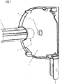
- the Fig. 1 shows an end portion of a winding shaft 1 of a building opening shading device z. B. in the form of a roller shutter, on which a not shown, formed by hinged slats formed in the form of a roller shutter curtain can be wound.
- the winding shaft 1 is located in a hanging box, indicated here only by a lateral cover cap 2, which usually has two lateral cover caps bridged by cladding sheets.
- a plug pin 3 which can be inserted into a guide rail which can be attached to the building, can be fixed directly or indirectly to the building and serve as a support device for transmitting the forces acting on the winding shaft 1 to the building.
- the cover cap 2 is provided with a receiving element here in the form of a bearing pin 4, on which the associated end of the winding shaft 1 with a suitable counter element, for. B. can be fitted with a suitable bearing bush.
- the winding shaft 1 is designed as a hollow shaft in the form of a section of a polygonal tube and on in Fig. 1 The end shown is provided with an inserted axle cap 5. At the opposite end of the winding shaft 1, a tubular motor can be plugged into this, which is flanged to the adjacent cover cap. If no tubular motor is provided and the winding shaft 1 is provided with a belt drive, axle caps 5 can be provided at both ends of the winding shaft 1.
- At least one axle cap 5 provided is designed to be telescopic.
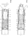
- the telescopic axle cap consists, like the FIGS. 2 to 5 show, of a tubular outer part 6 which can be inserted into the associated end of the winding shaft 1 and can be fixed therein, and a tubular outer part 6 which is arranged in the outer part 6 so as to be displaceable in the axial direction, from this according to FIG Fig. 2 partially extendable, tubular inner part 7, which is provided at its front end in the extension direction with a bearing device associated with the bearing pin 4 of the cover cap 2 in the form of a bearing stub 9 provided with a bearing bush 8.
- the extendable inner part 7 is biased in the direction of extension.
- an extension spring 10 encompassed by the inner part 7 and formed by a compression spring is provided, which is supported with its inner, ie rear end on a rear cover 11 of the outer part 6 and with its front end on an inner support flange 12 of the inner part 7.
- the Fig. 2 is based on the pushed-out position, ie the operating position of the inner part 7, in which, during operation, there is a support on the facing cap 2, not shown in detail here.
- the Fig. 3 shows the axle cap with the inner part inserted and, accordingly, the assembly position.
- the winding shaft 1 can first be brought with its telescopic axle cap 5 to engage the bearing pin 4 of the one blind cap 2, the inner part 7 being in the retracted assembly position or being brought into this.
- the inner part 7 is then extended into the operating position and the end of the winding shaft 1 opposite the telescopic axle cap 5 is attached to the second cover cap 2, for example with the tubular motor pushed into this end.
- the tubular motor can first be released and then the opposite axle cap 5 in the Fig. 3 underlying retracted position, so that it can be pulled off the bearing pin 4 of the associated cover cap 2 and the winding shaft 1 can be pivoted out of the associated box.
- the inner part 7 is centered with respect to the outer part 6 anchored in the winding shaft 1 and is supported axially and radially without play.
- a conical arrangement of several, here with two conical areas 13, 14 offset in the same direction in the same direction, is provided, which are each formed by outer conical surfaces 15 of the inner part 7 and inner conical surfaces 16 of the outer part 6, which are simultaneously inserted when the inner part 7 is extended mutual contact and thus limit the extension movement.
- two conical regions 13, 14 arranged one behind the other at a distance in the axial direction are provided. It would of course also be conceivable to provide several conical regions spaced apart from one another in the axial direction one behind the other.
- the conical surfaces 15, 16 run counter to that in FIG Fig. 2 by an arrow a indicated extension direction of increasing slope.
- the cone angle is dimensioned so that no self-hammering occurs. This is the case in the embodiment shown with the outer part 6 and inner part 7 designed as plastic parts at a cone angle of approximately 8 °. Since several arranged one behind the other Conical areas 13, 14 are provided, these can be made comparatively narrow. The width of the conical areas 13, 14 is therefore comparatively small compared to their mean diameter.
- the inner clear width of the winding shaft 1 specifies the maximum diameter of the axle cap 5 pushed into it and, accordingly, also the diameter of the outer part 6 and inner part 7. Since the conical areas 13, 14 are comparatively narrow, the front, d. H. outwardly facing end of the inner part 7 still has a comparatively large diameter, so that the bearing stub 9 adjoining the front conical area 13 of the inner part 7 and the bearing bush 8 received therein can also have comparatively large diameters and accordingly also the bearing journal 4 that can be brought into engagement with it can be heavily dimensioned.
- the inner part 7 can be designed in such a way that there is radial air in relation to the outer part 6 in the area between the two conical areas 13, 14, so that the inner part 7 does not collide with the outer part 6 even in the event of slight deformations and is therefore easy to move , which has an advantageous effect on the handling when installing and, in particular, removing the winding shaft 1.
- the outer part 6, which is based on a tubular body with the clear inner width of the winding shaft 1 corresponding outer diameter, is conically narrowed at its front, ie outwardly facing end to form the inner conical surface 16 of the front conical area 13 and with a to the front end of the Conical constriction adjoining radial flange 17 provided, which comes to rest on the end face of the winding shaft 1.
- the outer part 6 is provided with a radial indentation, the rear, ie inwardly facing, flank of which runs parallel to the front conical constriction, so that parallel front and rear inner conical surfaces 16 of the outer part 6 result.
- the Outer part 6 cylindrical support areas 20, 21 resting on the inner circumference of winding shaft 1.
- a radially projecting, circumferential collar 22 is provided, which has a conical jacket surface forming the outer conical surface 15 of the front conical area 13. All conical surfaces 15, 16 of the two conical areas 13, 14 are inclined in the same direction at the same cone angle.
- the axial distance between the outer conical surfaces 15 and the inner conical surfaces 16 of the front and rear conical areas 13, 14 is the same, so that the conical surfaces 15, 16 of all conical areas 13, 14 come into mutual contact when the inner part 7 is pushed out.
- the inner part 6, as from the FIGS. 2 and 3 It can be seen, in the area between its conical surfaces 15 assigned to the two conical areas 13, 14, provided with two locking teeth 23, 24, which are elastically movable in the radial direction, with radial locking surfaces 25 facing away from each other and facing wedge surfaces rising towards them.
- a locking tooth 23 or 24 is provided on the underlying positions.
- the distance between the two locking teeth 23, 24 is correspondingly adapted to the desired extension length of the inner part 7 in such a way that the distance between the locking teeth 23, 24 corresponds to the extension length minus the length of the locking recess 26 of the outer part 6.
- the rear locking tooth 24 and the associated outwardly facing edge of the locking recess 26 are of course positioned so that in the contact position of the two conical areas 13, 14, that is, there is still sufficient play for reliable locking.
- the locking teeth 23, 24 are molded onto the inner part 7, which is designed as a plastic part, and are separated from the rest of the tubular body on three sides by a U-shaped cutout to enable radial springing.
- the support flange 12 assigned to the extension spring 10 can also be molded onto the plastic part forming the inner part 7.
- the cover 11, which forms the rear spring bearing, of the outer part 6, which is also designed as a plastic part, can also be molded onto it.
- the cover 11 forming the rear spring bearing is designed as an insert cover which is expediently also made of plastic.
- the cover 11 can have a guide stub 27 engaging in the associated end of the extension spring 10.
- an unlocking button 28 engaging an unlocking member from the radially outside, ie opposite to the locking teeth 23 or 24, engages the locking recess 26, which is designed as a radial through recess , which is adapted in terms of cross-section to the cross-section of the locking recess 26.
- the unlocking button 28 can be felt and actuated from the outside when the curtain is unwound from the winding shaft.
- the winding shaft 1 is, as best, from Fig.
- the flange 30 is formed on part of its circumference as a tongue 31 protruding over the edge of the through recess 29 and reduced in thickness on the upper side by the wall thickness of the winding shaft 1, which when the axle cap 5 is pushed into the winding shaft 1, such as the Figs. 2 and 3 show, engages under the associated edge of the through recess 29 of the winding shaft 1, which results in a stop in the radial direction.
- the release button 28 automatically snaps into the through recess 29 with its flange 30 when the through recess 29 is reached by the action of the locking tooth 23 or 24. Since the unlocking button 28 simultaneously engages in the latching recess 26 of the outer part 6, this results in a fixation of the entire axle cap 5 relative to the winding shaft 1, so that the axle cap 5 is captively fixed therein.
- the unlocking button 28 engaging with its flange 30 in the through recess 29 can be felt from the radially outside when the curtain is unwound and can be operated manually without a tool, which ensures a high level of user-friendliness.
- actuating button 28 is provided on the circumference of the winding shaft 1.
- actuation buttons 28 preferably two actuation buttons 28 diametrically opposite one another, on the circumference of the winding shaft 1, which increases safety.
- the parts of the axle cap 5 in the form of the outer part 6 and the inner part 7 are how already mentioned as plastic parts, preferably designed as plastic injection moldings.
- the tubular body on which the outer part 6 is based is divided along a central longitudinal plane, so that the inner part 7 can easily be inserted.
- the two halves 6a of the outer part 6 are as if from Fig. 5 can be seen, provided in the area of the joint with locking and fixing members 32, 33 assigned to one another, and can accordingly be fixed to one another by a snap lock.
Landscapes
- Engineering & Computer Science (AREA)
- Structural Engineering (AREA)
- Architecture (AREA)
- Civil Engineering (AREA)
- Operating, Guiding And Securing Of Roll- Type Closing Members (AREA)
Description
- Die Erfindung betrifft eine teleskopierbare Achskappe für ein Ende einer Wickelwelle einer Gebäudeöffnungsverschattungsvorrichtung, wobei die Wickelwelle, auf die ein Behang aufwickelbar ist, als Hohlwelle ausgebildet und mit ihren Endbereichen auf gebäudeseitig anbringbaren Trageinrichtungen aufnehmbar ist und wobei die teleskopierbare Achskappe ein in das zugeordnete Ende der Wickelwelle einsteckbares und hierin fixierbares Außenteil und ein in diesem in axialer Richtung verschiebbares und teilweise aus diesem ausschiebbares, an seinem in Ausschubrichtung vorderen Ende mit einer mit der zugeordneten Trageinrichtung in Eingriff bringbaren Lagereinrichtung versehenes Innenteil aufweist, das in Ausfahrrichtung vorgespannt und zwischen einer eingefahrenen Montagestellung und einer ausgefahrenen Betriebsstellung und umgekehrt verschiebbar ist, in welcher es mit der zugeordneten Trageinrichtung zusammenwirken kann und mittels einer Konusanordung im Außenteil zentriert und axial und radial spielfrei hieran abgestützt ist.
- Eine Anordnung dieser Art ist aus der
DE 10 2014 003 497 A1 bekannt. Bei dieser bekannten Anordnung ist zur Bildung der Konusanordnung lediglich ein konischer Bereich vorgesehen, der dementsprechend alle Belastungen aufnehmen muss. Um dem Rechnung zu tragen, muss eine vergleichsweise groß Konusbreite vorgesehen werden. Dies führt jedoch ausgehend von einem gegebenen Wickelwellendurchmesser von normalerweise 40 mm und einem Konuswinkel im Bereich von 8° zu einem vergleichsweise kleinen Durchmesser des vorderen nach außen gerichteten Kegelendes und damit des hieran anschließenden Lagerelements, was sich sehr ungünstig auf die erzielbare Tragfähigkeit auswirkt. In diesem Zusammenhang ist nämlich davon auszugehen, dass es sich beiden Teilen der teleskopierbaren Achskappe normalerweise um Kunststoffteile handelt. Sofern jedoch ein für die Tragfähigkeit des Lagerelements ausreichender Durchmesser vorgesehen wird, ergibt sich aufgrund der durch den Durchmesser der Wickelwelle gegebenen Beschränkungen eine vergleichsweise kleine Konusbreite, so dass die Tragfähigkeit im Bereich der Konusanordnung beschränkt ist. Bei der bekannten Anordnung ergibt sich daher so oder so eine unerwünschte Beschränkung der Tragfähigkeit. - Hiervon ausgehend ist es daher die Aufgabe der vorliegenden Erfindung, eine teleskopierbare Achskappe eingangs erwähnter Art mit einfachen und kostengünstigen Mitteln so zu verbessern, dass die Vorteile der Konusanordnung hinsichtlich spielfreier Abstützung und Zentrierung des Innenteils im Außenteil beibehalten und dennoch eine hohe Tragfähigkeit gewährleistet werden.
- Diese Aufgabe wird erfindungsgemäß dadurch gelöst, dass die Konusanordnung mehrere, in axialer Richtung voneinander distanzierte, gleichsinnig geneigte Konunsbereiche mit gleichzeitig in gegenseitiger Anlage kommenden, äußeren Konusflächen des Innenteils und inneren Konusflächen des Außenteils aufweist.
- Mit diesen Maßnahmen werden die Nachteile der bekannten Anordnung vermieden und ihre Vorteile beibehalten. Da mehrere Konusbereiche vorgesehen sind, ist sichergestellt, dass deren Breite vergleichsweise klein sein kann, so dass auch unter den Beschränkungen des Durchmessers der Wickelwelle ein vergleichsweise großer Durchmesser der vorderen Lagereinrichtung und damit eine gute Tragfähigkeit erreicht werden. Gleichzeitig ergibt sich eine Verteilung der über die Konusanordnung zu übertragenden Kräfte auf mehrere Konusbereiche und damit ebenfalls eine entsprechende Entlastung jedes einzelnen Konusbereichs. Da die Konusflächen der mehreren Konusbereiche gleichzeitig in gegenseitiger Anlage kommen ist sichergestellt, dass sich auch eine zuverlässige Zentrierung und eine spielfreie gegenseitige Abstützung ergeben. Außerdem ist gewährleistet, dass das Innenteil im Bereich zwischen den Konusbereichen radiale Luft gegenüber dem Außenteil haben kann, so dass das Innenteil, das bei hohen Belastungen in Folge eines hohen Behanggewichts und/oder hoher Temperaturen seine exakte Form verlieren kann, dennoch leicht verschieblich bleibt, was sich vorteilhaft auf die Zuverlässigkeit auswirkt.
- Vorteilhafte Ausgestaltungen und zweckmäßige Fortbildungen der übergeordneten Maßnahmen sind in den Unteransprüchen angegeben.
- So können zur Bildung der Konusanordnung vorzugsweise zwei Konusbereiche vorgesehen sein, von denen einer dem vorderen, nach außen weisenden Ende des Außenteils und einer dem hinteren, nach innen weisenden Ende des Innenteils zugeordnet sein können. Dies ergibt in vorteilhafter Weise eine übersichtliche Bauform mit einem vergleichsweise großen Abstand der beiden Konusbereiche und damit eine statisch bestimmte Anordnung mit günstigem Kraftfluss. Die beiden Konusbreiche benötigen in vorteilhafter Weise auch eine im Vergleich zu ihrem Durchmesser nur vergleichsweise kleine Breite, so dass ein vergleichsweise großer Durchmesser der am vorderen Ende des Innenteils vorgesehene Lagereinrichtung erreicht wird.
- In weiterer Fortbildung der übergeordneten Maßnahmen ist das rohrförmige Außenteil, das einen der lichten äußeren Weite der Wickelwelle entsprechenden Außendurchmesser aufweist, am vorderen Ende konisch verengt und mit einem an der Stirnseite der Wickelwelle zur Anlage bringbaren Flansch versehen und im Bereich zwischen zwei an der Wickelwelle anliegenden Bereichen mit einer Einziehung versehen, die eine konisch geformte, hintere Flanke aufweist. Das zugehörige, ebenfalls rohrförmige Innenteil kann zweckmäßig einen gegenüber dem Innendurchmesser des Außenteils verkleinerten Außendurchmesser aufweisen und am hinteren Ende konisch aufgeweitet und mit dem Abstand der Konusflächen des Außenteils entsprechendem Abstand weiter vorne mit einem umlaufenden Bund mit konischem Außenmantel versehen sein. Hierdurch ergibt sich eine kompakte Anordnung mit einfach an das Außenteil und Innenteil angeformten Konusflächen. Um das Innenteil leicht in das Außenteil einlegen zu können, kann dieses zweckmäßig aus zwei aneinander festlegbaren Hälften bestehen.
- In weiterer Fortbildung der übergeordneten Maßnahmen kann das Innenteil im Bereich zwischen seinen Konusflächen eine Rasteinrichtung mit wenigstens zwei Rastzähnen und mit voneinander abgewandten Sperrflächen aufweisen, deren Abstand an die gewünschte Ausschublänge des Innenteils angepasst ist. Das Außenteil kann vorteilhaft eine radial durchgehende Rastausnehmung aufweisen, in welche die Rastzähne wechselweise einrastbar sind und wobei auf der Wickelwelle ein von außen betätigbares Entriegelungsorgan vorgesehen ist, das gegenläufig zu den Rastzähnen zum Eingriff in die Rastausnehmung bringbar ist. Die Rastzähne rasten beim Erreichen der jeweils zugeordneten Position des Innenteils in Folge ihrer Federeigenschaft automatisch in die Rastausnehmung des Außenteils ein, was sich vorteilhaft auf die erzielbare Sicherheit auswirkt. Das Entriegelungsorgan kann bei abgewickeltem Behang einfach von außen ertastet und manuell, d. h. werkzeuglos, betätigt werden. Es ergibt sich daher eine hohe Bedienungsfreundlichkeit.
- Ein weitere vorteilhafte Maßnahme kann darin bestehen, dass das Entriegelungsorgan als querschnittsmäßig an die Rastausnehmung des Außenteils angepasster Knopf ausgebildet ist, der oben eine in eine zugeordnete Durchgangsausnehmung der Wickelwelle eingreifende und deren Rand teilweise untergreifende Erweiterung aufweist. Diese Maßnahmen ergeben in vorteilhafter Weise nicht nur eine einfache und zuverlässige Entriegelbarkeit des Innenteils gegenüber dem Außenteil sondern ermöglichen gleichzeitig auch einen lösbaren Schnappverschluss zwischen dem Außenteil und damit zwischen der gesamten Achskappe und der Wickelwelle, so dass die Achskappe in vorteilhafter Weise verliersicher in der Wickelwelle aufnehmbar ist und eine bisher für erforderlich gehaltene Verprägung etc. entfallen kann.
- Weitere vorteilhafte Ausgestaltungen und zweckmäßige Fortbildungen der übergeordneten Maßnahmen sind in den restlichen Unteransprüchen angegeben und aus der nachstehenden Beispielsbeschreibung anhand der Zeichnung näher entnehmbar.
- In der nachstehend beschriebenen Zeichnung zeigen:
- Fig. 1
- Eine Innenansicht einer seitlichen Blendkappe eines Behangkastens mit zugeordnetem Endbereich einer Wickelwelle,
- Fig. 2
- einen Schnitt durch die mit einer teleskopierbaren Achskappe versehene Wickelwelle in der Betriebsstellung,
- Fig. 3
- die Anordnung gemäß
Fig. 2 in der Montagestellung, - Fig. 4
- die Anordnung gemäß
Fig. 2 bei der Vormontage der Achskappe und - Fig. 5
- eine Ansicht einer Hälfte des geteilten Außenteils der Achskappe.
- Die Erfindung eignet sich für alle Vorrichtungen, wie Rollläden, Textil-Screens etc., bei denen eine auf seitlichen Trageinrichtungen aufnehmbare Wickelwelle für ein einen Behang vorgesehen ist.
- Die
Fig. 1 zeigt einen Endbereich einer Wickelwelle 1 einer Gebäudeöffnungsverschattungsvorrichtung z. B. in Form eines Rollladens, auf die ein nicht näher gezeigter, durch gelenkig miteinander verbundene Lamellen gebildeter Behang in Form eines Rollladenpanzers aufwickelbar ist. Die Wickelwelle 1 befindet sich in einem hier lediglich durch eine seitliche Blendkappe 2 angedeuteten Behangkasten, der in der Regel zwei seitliche, durch Mantelbleche überbrückte Blendkappen aufweist. Diese sind wie inFig. 1 durch einen in eine gebäudeseitig anbringbare Führungsschiene einsteckbaren Steckzapfen 3 angedeutet ist, direkt oder indirekt am Gebäude festlegbar und dienen als Trageinrichtung zur Übertragung der an der Wickelwelle 1 angreifenden Kräfte auf das Gebäude. Zur Aufnahme der Wickelwelle 1 ist die Blendkappe 2 mit einem Aufnahmeelement hier in Form eines Lagerzapfens 4 versehen, auf den das zugeordnete Ende der Wickelwelle 1 mit einem geeigneten Gegenelement, z. B. mit einer geeigneten Lagerbüchse aufsteckbar ist. - Die Wickelwelle 1 ist als Hohlwelle in Form eines Abschnitts eines Mehrkantrohrs ausgebildet und am in
Fig. 1 gezeigten Ende mit einer eingesteckten Achskappe 5 versehen. Am gegenüberliegenden Ende der Wickelwelle 1 kann in diese ein Rohrmotor eingesteckt sein, der an die benachbarte Blendkappe angeflanscht wird. Sofern kein Rohrmotor vorgesehen und die Wickelwelle 1 mit einem Gurtantrieb versehen ist, können an beiden Enden der Wickelwelle 1 Achskappen 5 vorgesehen sein. - Um eine einfache Montage und Demontage der Wickelwelle 1 beispielsweise zu Revisionszwecken etc. zu ermöglichen, ist zumindest eine vorgesehene Achskappe 5 teleskopierbar ausgebildet. Die teleskopierbare Achskappe besteht, wie die
Fig. 2 bis Fig. 5 zeigen, aus einem in das zugeordnete Ende der Wickelwelle 1 einsteckbaren und hierin fixierbaren, rohrförmigen Außenteil 6 und einem im Außenteil 6 in axialer Richtung verschiebbar angeordneten, aus diesem gemäßFig. 2 teilweise ausfahrbaren, rohrförmigen Innenteil 7, das an seinem in Ausschubrichtung vorderen Ende mit einer den Lagerzapfen 4 der Blendkappe 2 zugeordneten Lagereinrichtung in Form eines mit einer Lagerbüchse 8 versehenen Lagerstutzen 9 versehen ist. Das ausfahrbare Innenteil 7 ist in Ausfahrrichtung vorgespannt. Hierzu ist eine vom Innenteil 7 umfasste, durch eine Druckfeder gebildete Ausschubfeder 10 vorgesehen, die mit ihrem inneren, d. h. hinteren Ende an einem hinteren Deckel 11 des Außenteils 6 und mit ihrem vorderen Ende an einem inneren Stützflansch 12 des Innenteils 7 abgestützt ist. DerFig. 2 liegt die ausgeschobene Position, d. h. die Betriebsposition des Innenteils 7 zugrunde, in der im Betrieb eine Abstützung auf der hier nicht näher dargestellten Blendkappe 2 erfolgt. DieFig. 3 zeigt die Achskappe mit eingeschobenen Innenteil und dementsprechend die Montageposition. - Zur Montage der Wickelwelle 1 auf den beiden zugeordneten Blendkappen 2 kann die Wickelwelle 1 zunächst mit ihrer teleskopierbaren Achskappe 5 zum Eingriff mit dem Lagerzapfen 4 der einen Blendkappe 2 gebracht werden, wobei das Innenteil 7 in der eingefahrenen Montagestellung ist oder in diese gebracht wird. Anschliepend werden das Innenteil 7 in die Betriebsstellung ausgefahren und das der teleskopierbaren Achskappe 5 gegenüberliegende Ende der Wickelwelle 1, beispielsweise mit dem in dieses Ende eingeschobenen Rohrmotor, an der zweiten Blendkappe 2 angebracht. Bei der Demontage wird in umgekehrter Reihenfolge vorgegangen. Dabei können zunächst der Rohrmotor gelöst und dann die gegenüberliegende Achskappe 5 in die der
Fig. 3 zugrunde liegende eingefahrene Stellung gebracht werden, so dass sie vom Lagerzapfen 4 der zugeordneten Blendkappe 2 abgezogen und die Wickelwelle 1 aus dem zugeordneten Kasten herausgeschwenkt werden kann. - In der der
Fig. 2 zugrunde liegenden Betriebsposition ist das Innenteil 7 gegenüber dem in der Wickelwelle 1 verankerten Außenteil 6 zentriert und axial und radial spielfrei abgestützt. Hierzu ist eine Konusanordnung mehreren, hier mit zwei in axialer Richtung gegeneinander versetzten, gleichsinnig geneigten Konusbereichen 13, 14 vorgesehen, die jeweils durch äußere Konusflächen 15 des Innenteils 7 und innere Konusflächen 16 des Außenteils 6 gebildet werden, die beim Ausfahren des Innenteils 7 gleichzeitig in gegenseitige Anlage kommen und damit die Ausfahrbewegung begrenzen. Im dargestellten Beispiel sind zwei in axialer Richtung mit Abstand hintereinander angeordnete Konusbereiche 13, 14 vorgesehen. Es wäre natürlich auch denkbar, mehrere in axialer Richtung voneinander distanzierte Konusbereiche hintereinander vorzusehen. - Die Konusflächen 15, 16 verlaufen mit entgegen der in
Fig. 2 durch einen Pfeil a angedeuteten Ausfahrrichtung ansteigender Schräge. Der Konuswinkel ist so bemessen, dass keine Selbsthämmung eintritt. Das ist bei der dargestellten Ausführung mit als Kunststoffteile ausgebildetem Außenteil 6 und Innenteil 7 bei einem Konuswinkel vom etwa 8° der Fall. Da mehrere hintereinander angeordnete Konusbereiche 13, 14 vorgesehen sind, können diese vergleichsweise schmal ausgebildet sein. Die Breite der Konusbereiche 13, 14 ist daher im Vergleich zu ihrem mittleren Durchmesser vergleichsweise klein. - Die innere lichte Weite der Wickelwelle 1 gibt den maximalen Durchmesser der in diese eingeschobenen Achskappe 5 und dementsprechend auch den Durchmesser des Außenteils 6 und Innenteils 7 vor. Da die Konusbereiche 13, 14 vergleichsweise schmal sind, ergibt sich am vorderen, d. h. nach außen gewandten Ende des Innenteils 7 noch ein vergleichsweise großer Durchmesser, so dass auch der an den vorderen Konusbereich 13 des Innenteils 7 anschließende Lagerstutzen 9 und die hierin aufgenommene Lagerbüchse 8 vergleichsweise große Durchmesser aufweisen können und dementsprechend auch der hiermit zum Eingriff bringbare Lagerzapfen 4 entsprechend stark dimensioniert sein kann. Gleichzeitig kann das Innenteil 7 so gestaltet sein, dass im Bereich zwischen den beiden Konusbereichen 13, 14 radiale Luft gegenüber dem Außenteil 6 gegeben ist, so dass das Innenteil 7 auch im Falle leichter Verformungen nicht mit dem Außenteil 6 kollidiert und daher dennoch leicht verschiebbar ist, was sich vorteilhaft auf die Handhabung beim Ein- und insbesondere Ausbau der Wickelwelle 1 auswirkt.
- Das Außenteil 6, dem ein rohrförmiger Körper mit der lichten Innenweite der Wickelwelle 1 entsprechenden Außendurchmesser zugrunde liegt, ist an seinem vorderen, d. h. nach außen weisenden Ende zur Bildung der inneren Konusfläche 16 des vorderen Konusbereichs 13 konisch verengt und mit einem an das vordere Ende der konischen Verengung anschießenden Radialflansch 17 versehen, der an der Stirnseite der Wickelwelle 1 zur Anlage kommt. Im mittleren Längenbereich ist das Außenteil 6 mit einer radialen Einziehung versehen, deren hintere, d. h. nach innen gewandte Flanke parallel zur vorderen konischen Verengung verläuft, so dass sich parallele vordere und hintere innere Konusflächen 16 des Außenteils 6 ergeben. Im Bereich zwischen der vorderen konischen Verengung und der im mittleren Bereich vorgesehenen Einziehung sowie im Bereich zwischen der hinteren Flanke der Einziehung und dem rückwärtigen Deckel 11 besitzt das Außenteil 6 am Innenumfang der Wickelwelle 1 anliegende zylindrische Stützbereiche 20, 21.
- Das Innenteil 7, das ebenfalls von einem rohrförmigen Körper aber mit einem gegenüber dem Innendurchmesser des Außenteils 6 kleineren Außendurchmesser ausgeht, ist, wie die
Fig. 2 und Fig. 3 ebenfalls zeigen, an seinem hinteren, d. h. nach innen gewandten Ende zur Bildung der äußeren Konusfläche 15 des hinteren Konusbereichs 14 trichterförmig aufgeweitet. Im Bereich des hinteren Endes des Lagerstutzens 9 ist ein radial vorspringender, umlaufender Bund 22 vorgesehen, der eine die äußere Konusfläche 15 des vorderen Konusbereichs 13 bildende, konische Mantelfläche aufweist. Alle Konusflächen 15, 16 der beiden Konusbereiche 13, 14 sind unter demselben Konuswinkel gleichsinnig geneigt. Der axiale Abstand der äußeren Konusflächen 15 und der inneren Konusflächen 16 des vorderen und hinteren Konusbereichs 13, 14 ist gleich, so dass die Konusflächen 15, 16 sämtlicher Konusbereiche 13, 14 beim Ausschieben des Innenteils 7 gleichzeitig in gegenseitige Anlage kommen. - Das bis zur gegenseitigen Anlage der Konusflächen 15, 16 aus dem Außenteil 6 ausschiebbare Innenteil 7 ist gegenüber dem stationären Außenteil 6 sowohl in der der
Fig. 2 zugrunde liegenden Betriebsposition als auch in der derFig. 3 zugrunde liegenden Montageposition verrastbar und so gegen unerwünschte axiale Ortsveränderung gesichert. Hierzu ist das Innenteil 6, wie aus denFig. 2 und Fig. 3 ersichtlich ist, im Bereich zwischen seinen den beiden Konusbereichen 13, 14 zugeordneten Konusflächen 15 mit zwei in radialer Richtung elastisch beweglichen Rastzähnen 23, 24 mit voneinander abgewandten radialen Sperrflächen 25 und zu diesen ansteigenden, einander zugewandten Keilflächen versehen. Für jede der denFig. 2 und Fig. 3 zugrundeliegenden Positionen ist ein Rastzahn 23 bzw. 24 vorgesehen. Dieser ist in der jeweils zugeordneten Betriebsposition bzw. Montageposition des Innenteils 7 in eine Rastausnehmung 26 des Außenteils 6 einrastbar, wobei sich in der derFig. 2 zugrunde liegenden Betriebsposition des Innenteils 7 der hintere Rastzahn 24 an der nach außen, d. h. zum äußeren Ende der Achskappe 5 weisenden Randkante der Rastausnehmung 26 und in derFig. 3 zugrunde liegenden Montageposition des Innenteils 7 der vordere Rastzahn 23 an der in Ausschubrichtung nach innen, d, h. zum inneren Ende der Achskappe 5 weisenden Randkante der Rastausnehmung 26 abstützen. Der Abstand der beiden Rastzähne 23, 24 ist dementsprechend an die gewünschte Ausfahrlänge des Innenteils 7 angepasst und zwar derart, dass der Abstand der Rastzähne 23, 24 der Ausfahrlänge abzüglich der Länge der Rastausnehmung 26 des Außenteils 6 entspricht. Der hintere Rastzahn 24 und die diesem zugeordnete nach außen weisende Randkante der Rastausnehmung 26 sind natürlich so positioniert, dass in der Anlagestellung der beiden Konusbereiche 13, 14, d. h. gegenüber dieser noch ausreichend Spiel für eine zuverlässige Einrastung besteht. - Die Rastzähne 23, 24 sind an das als Kunststoffteil ausgebildete Innenteil 7 angeformt und dabei zur Ermöglichung einer radialen Federung durch einen U-förmigen Freischnitt an drei Seiten vom sonstigen Rohrkörper getrennt. Der der Ausschubfeder 10 zugeordnete Stützflansch 12 kann ebenfalls an das das Innenteil 7 bildende Kunststoffteil angeformt sein. Der das rückwärtige Federlager bildende Deckel 11 des ebenfalls als Kunststoffteil ausgebildeten Außenteil 6 kann ebenfalls an dieses angeformt sein. Im dargestellten Beispiel ist der das rückwärtige Federlager bildende Deckel 11 als zweckmäßig ebenfalls aus Kunststoff bestehender Einlegedeckel ausgebildet. In jedem Fall kann der Deckel 11 einen in das zugeordnete Ende der Ausschubfeder 10 eingreifenden Führungsstutzen 27 aufweisen.
- Zur Entriegelung des Innenteils 7, d. h. zum Außereingriffbringen des jeweiligen Rastzahns 23 bzw. 24 mit der Rastausnehmung 26 ist ein von radial außen, d. h. gegenläufig zu den Rastzähnen 23 bzw. 24 in die als radiale Durchgangsausnehmung ausgebildete Rastausnehmung 26 eingreifender ein Entriegelungsorgan bildender Entriegelungsknopf 28 vorgesehen, der querschnittsmäßig an den Querschnitt der Rastausnehmung 26 angepasst ist. Der Entriegelungsknopf 28 ist bei von der Wickelwelle abgewickeltem Behang von außen ertastbar und betätigbar. Hierzu ist die Wickelwelle 1, wie am besten aus
Fig. 4 erkennbar ist, mit einer dem Entriegelungsknopf 28 zugeordneten, radialen Durchgangsausnehmung 29 versehen, die querschnittsmäßig etwas größer als die Rastausnehmung 26 des Außenteils 6 ist und die der Entriegelungsknopf 28, wie in denFig. 2 und Fig. 3 dargestellt ist, mit einem eine obere Erweiterung bildenden oberen Flansch 30 eingreift, so dass sich eine in der Wickelwelle 1 versenkte und damit die Wicklung des Behangs nicht störende Anordnung ergibt. Der Flansch 30 ist auf einem Teil seines Umfangs als über den Rand der Durchgangsausnehmung 29 auskragende und an der Oberseite um die Wandstärke der Wickelwelle 1 in der Dicke reduzierte Zunge 31 ausgebildet, welche bei in die Wickelwelle 1 eingeschobener Achskappe 5, wie dieFig. 2 und 3 zeigen, den zugeordneten Rand der Durchgangsausnehmung 29 der Wickelwelle 1 untergreift, wodurch sich ein Anschlag in radialer Richtung ergibt. - Beim Einschieben der Achskappe 5 in den der Wickelwelle 1 zugrunde liegenden Rohrabschnitt schnappt der Entriegelungsknopf 28 beim Erreichen der Durchgangsausnehmung 29 mit seinem Flansch 30 durch die Wirkung des Rastzahns 23 oder 24 automatisch in die Durchgangsausnehmung 29 ein. Da der Entriegelungsknopf 28 gleichzeitig in die Rastausnehmung 26 des Außenteils 6 eingreift, ergibt sich hierdurch eine Fixierung der gesamten Achskappe 5 gegenüber der Wickelwelle 1, so dass die Achskappe 5 hierin unverlierbar fixiert ist. Der mit seinem Flansch 30 in die Durchgangsausnehmung 29 eingreifende Entriegelungsknopf 28 ist bei abgewickeltem Behang von radial außen ertastbar und ohne Werkzeug manuell betätigbar, was eine hohe Bedienungsfreundlichkeit gewährleistet.
- Im dargestellten Beispiel ist lediglich ein Betätigungsknopf 28 am Umfang der Wickelwelle 1 vorgesehen. Es wäre aber auch denkbar, am Umfang der Wickelwelle 1 mehrere Betätigungsknöpfe 28, vorzugsweise zwei einander diametral gegenüberliegende Betätigungsknöpfe 28 vorzusehen, was die Sicherheit erhöht.
- Die Teile der Achskappe 5 in Form des Außenteils 6 und des Innenteils 7 sind, wie schon erwähnt als Kunststoffteile, vorzugsweise als Kunststoff-Spritzgussformlinge ausgebildet. Der dem Außenteil 6 zugrunde liegende Rohrkörper ist dabei entlang einer Mittellängsebene geteilt, so dass das Innenteil 7 einfach eingelegt werden kann. Die beiden Hälften 6a des Außenteils 6, sind wie aus
Fig. 5 erkennbar ist, im Bereich der Teilfuge mit einander zugeordneten Rast- und Fixierorganen 32, 33 versehen, und können dementsprechend durch einen Schnappverschluss aneinander festgelegt werden.
Claims (10)
- Teleskopierbare Achskappe für ein Ende einer Wickelwelle (1) einer Gebäudeöffnungsverschattungsvorrichtung, wobei die Wickelwelle (1), auf die ein Behang aufwickelbar ist, als Hohlwelle ausgebildet und mit ihren Endbereichen auf gebäudeseitig anbringbaren Trageinrichtungen (2) aufnehmbar ist und wobei die teleskopierbare Achskappe (5) ein in das zugeordnete Ende der Wickelwelle (1) einsteckbares und hierin fixierbares Außenteil (6) und ein in diesem in axialer Richtung verschiebbares und teilweise aus diesem ausschiebbares, an seinem in Ausschubrichtung vorderen Ende mit einer mit der zugeordneten Trageinrichtung (2) in Eingriff bringbaren Lagereinrichtung (8, 9) versehenes Innenteil (7) aufweist, das in Ausfahrrichtung vorgespannt und zwischen einer eingefahrenen Montagestellung und einer ausgefahrenen Betriebsstellung und umgekehrt verstellbar ist, in welcher ep mit der zugeordneten Trageinrichtung (2) zusammenwirken kann und mittels einer Konusanordnung im Außenteil (6) zentriert und axial und radial spielfrei hieran abgestützt ist, dadurch gekennzeichnet, dass die Konusanordnung mehrere, in axialer Richtung voneinander distanzierte, gleichsinnig geneigte Konusbereiche (13, 14) mit gleichzeitig in gegenseitige Anlage kommenden, äußeren Konusflächen (15) des Innenteils (7) und inneren Konusflächen (16) des Außenteils (6) aufweist.
- Teleskopierbare Achskappe an Anspruch 1, dadurch gekennzeichnet, dass die Konusanordnung zwei Konusbereiche (13, 14) aufweist, wobei der erste Konusbereich (13) dem vorderen Ende des Außenteils (6) und der zweite Konusbereich (14) dem hinteren Ende des Innenteils (7) zugeordnet sind.
- Teleskopierbare Achskappe nach Anspruch 2, dadurch gekennzeichnet, dass das Innenteil (7) im Bereich zwischen beiden Konusbereichen (13, 14) gegenüber dem Außenteil (6) radiale Luft hat.
- Teleskopierbare Achskappe nach einem der vorhergehenden Ansprüche, dadurch gekennzeichnet, dass die Breite der Konusbereiche (13, 14) im Vergleich zu ihrem Durchmesser klein ist.
- Teleskopierbare Achskappe nach einem der vorhergehenden Ansprüche, dadurch gekennzeichnet, dass dem Außenteil (6) ein vorzugsweise entlang einer Mittellängsebene geteiltes Rohr mit einem der lichten Innenweite der Wickelwelle (1) entsprechenden Außendurchmesser zugrunde liegt, das am vorderen Ende zur Bildung der Konusfläche (16) des vorderen Konusbereichs (13) konisch verengt und mit einem an der Stirnseite der Wickelwelle (1) zur Anlage bringbaren Flansch (17) versehen ist und das im Bereich zwischen zwei an der Wickelwelle (1) anliegenden Stützbereichen (20,21) eine Einziehung mit einer zur Bildung der Konusfläche (16) des hinteren Konusbereichs (14) konischen hinteren Flanke aufweist.
- Teleskopierbare Achskappe nach einem der vorhergehenden Ansprüche, dadurch gekennzeichnet, dass dem Innenteil (7) ein Rohr mit gegenüber dem Innendurchmesser des Außenteils (8) verkleinertem Außendurchmesser zugrunde liegt, das am hinteren Ende zur Bildung der Konusfläche (15) des hinteren Konusbereichs (14) aufgeweitet ist und mit dem Abstand zwischen den Konusflächen (16) des Außenteils (6) entsprechendem Abstand weiter vorne mit einem umlaufenden Bund (22) mit einem zur Bildung der Konusfläche (16) des vorderen Konusbereichs (13) konischen Außenmantel versehen ist.
- Teleskopierbare Achskappe nach einem der vorhergehenden Ansprüche, dadurch gekennzeichnet, dass das Innenteil (7) im Bereich zwischen seinen Konusflächen (15) eine Rasteinrichtung mit wenigstens zwei Rastzähnen (23, 24) mit voneinander abgewandten radialen Sperrflächen (25) aufweist, deren Abstand an die gewünschte Ausschublänge des Innenteils (7) angepasst ist, und dass das Außenteil (6) eine in radialer Richtung durchgehende Rastausnehmung (26) aufweist, in welche die Rastzähne (23, 24) wechselweise einrastbar sind und wobei auf der Wickelwelle (1) ein von außen betätigbares Entriegelungsorgan (28) vorgesehen ist, das gegenläufig zu den Rastzähnen (23, 24) in Eingriff in die Rastausnehmung (26) bringbar ist.
- Teleskopierbare Achskappe nach Anspruch (7), dadurch gekennzeichnet, dass die Rastzähne (23,24) einander zugewandte, zu ihren Sperrflächen (25) ansteigende Keilflächen aufweisen.
- Teleskopierbare Achskappe nach einem der vorhergehenden Ansprüche, dadurch gekennzeichnet, dass dem Innenteil (7) eine Ausschubfeder (10) zugeordnet ist, die einerseits an einem Innenflansch (12) des Innenteils (7) und andererseits an einem hinteren, vorzugsweise eingelegten Deckel (11) des Außenteils (6) abgestützt ist.
- Teleskopierbare Achskappe nach einem der vorhergehenden Ansprüche 7 oder 8, dadurch gekennzeichnet, dass das Entriegelungsorgan (28) der Rasteinrichtung des Innenteils (7) als querschnittsmäßig an die Rastausnehmung (26) des Außenteils (6) angepasster Knopf ausgebildet ist, der radial oben einen in eine zugeordnete Durchgangsausnehmung (29) der Wickelwelle (1) eingreifenden Flansch (30) und eine den Rand der Durchgangsausnehmung (29) teilweise untergreifende Zunge (31) aufweist.
Applications Claiming Priority (1)
| Application Number | Priority Date | Filing Date | Title |
|---|---|---|---|
| DE102018006498.1A DE102018006498B3 (de) | 2018-08-17 | 2018-08-17 | Teleskopierbare Achskappe |
Publications (2)
| Publication Number | Publication Date |
|---|---|
| EP3611328A1 EP3611328A1 (de) | 2020-02-19 |
| EP3611328B1 true EP3611328B1 (de) | 2021-07-07 |
Family
ID=67514276
Family Applications (1)
| Application Number | Title | Priority Date | Filing Date |
|---|---|---|---|
| EP19020451.1A Active EP3611328B1 (de) | 2018-08-17 | 2019-08-01 | Teleskopierbare achskappe |
Country Status (2)
| Country | Link |
|---|---|
| EP (1) | EP3611328B1 (de) |
| DE (1) | DE102018006498B3 (de) |
Cited By (1)
| Publication number | Priority date | Publication date | Assignee | Title |
|---|---|---|---|---|
| EP4446557A1 (de) | 2023-04-14 | 2024-10-16 | Roma Kg | Aufsatzrollladenkasten sowie bodenbrett und bodenbrett-montageprofil hierfür |
Family Cites Families (3)
| Publication number | Priority date | Publication date | Assignee | Title |
|---|---|---|---|---|
| DE4010209C2 (de) * | 1990-03-30 | 1994-03-10 | Baumeister & Ostler Gmbh Co | Sicherheitsnetz |
| DE102014003497B4 (de) | 2014-03-14 | 2021-02-25 | Roma Kg | Gebäudeöffnungsverschattungsvorrichtung mit einem Achskappenmodul für die Wickelwelle der Gebäudeöffnungsverschattungsvorrichtung |
| CN106308426B (zh) * | 2015-06-23 | 2019-03-08 | 皇田工业股份有限公司 | 遮物帘的伸缩边杆 |
-
2018
- 2018-08-17 DE DE102018006498.1A patent/DE102018006498B3/de not_active Expired - Fee Related
-
2019
- 2019-08-01 EP EP19020451.1A patent/EP3611328B1/de active Active
Non-Patent Citations (1)
| Title |
|---|
| None * |
Cited By (1)
| Publication number | Priority date | Publication date | Assignee | Title |
|---|---|---|---|---|
| EP4446557A1 (de) | 2023-04-14 | 2024-10-16 | Roma Kg | Aufsatzrollladenkasten sowie bodenbrett und bodenbrett-montageprofil hierfür |
Also Published As
| Publication number | Publication date |
|---|---|
| EP3611328A1 (de) | 2020-02-19 |
| DE102018006498B3 (de) | 2019-12-12 |
Similar Documents
| Publication | Publication Date | Title |
|---|---|---|
| EP3149354B1 (de) | Teleskopierbare federstütze | |
| EP3027826B1 (de) | Gerüstrohr eines baugerüsts und gerüstelement | |
| EP0465896A1 (de) | Verbindungselement für Wellrohre und Schläuche | |
| EP3098461B1 (de) | Rastbolzen | |
| EP3611329B1 (de) | Teleskopierbare achskappe | |
| EP2513391A1 (de) | Teleskopstütze für den baubereich | |
| EP3577012B1 (de) | Längsverstellbare lenkwelle für ein kraftfahrzeug und profilhülse für eine lenkwelle | |
| EP2574799B1 (de) | Teleskopierbare Verbindungsanordnung | |
| DE102005034063B3 (de) | Vorrichtung zum Verschließen von Gebäudeöffnungen | |
| EP2918768B1 (de) | Gebäudeöffnungsverschattungsvorrichtung | |
| DE102018006498B3 (de) | Teleskopierbare Achskappe | |
| DE2262508B2 (de) | Loesbare verbindungsanordnung fuer einen rohrstutzen und einen schlauch | |
| EP0446448A1 (de) | Verbindungseinrichtung für Druckmittelleitungen od. dgl. | |
| DE102014003497B4 (de) | Gebäudeöffnungsverschattungsvorrichtung mit einem Achskappenmodul für die Wickelwelle der Gebäudeöffnungsverschattungsvorrichtung | |
| EP2320136A1 (de) | Einbaurahmen mit Befestigungsvorrichtung | |
| EP3921554B1 (de) | Gleitelement | |
| EP3453569A1 (de) | Sperrbalken | |
| DE102013211864B4 (de) | Anordnung zur Befestigung eines Pfostens an einer Kunststoff-Rahmenleiste eines Fensters oder einer Türe mittels eines Pfostenverbinders aus Kunststoff | |
| DE102013000278B4 (de) | Gebäudeöffnungsverschattungsvorrichtung und Achskappenmodul für die Wickelwelle der Gebäudeöffnungsverschattungsvorrichtung | |
| EP3795420A1 (de) | Sperrbalken | |
| DE9110687U1 (de) | Linearantrieb | |
| DE20207715U1 (de) | Teleskopleiter | |
| DE10015506C2 (de) | Teleskophalter | |
| DE29702789U1 (de) | Teleskopierbares Staubsauger-Saugrohr | |
| DE102016119519A1 (de) | Lenksäulenmodul für ein Fahrzeug, Lenksäulenanordnung, Fahrzeug und Verfahren zum Zusammenbau einer Lenksäulenanordnung |
Legal Events
| Date | Code | Title | Description |
|---|---|---|---|
| PUAI | Public reference made under article 153(3) epc to a published international application that has entered the european phase |
Free format text: ORIGINAL CODE: 0009012 |
|
| STAA | Information on the status of an ep patent application or granted ep patent |
Free format text: STATUS: THE APPLICATION HAS BEEN PUBLISHED |
|
| AK | Designated contracting states |
Kind code of ref document: A1 Designated state(s): AL AT BE BG CH CY CZ DE DK EE ES FI FR GB GR HR HU IE IS IT LI LT LU LV MC MK MT NL NO PL PT RO RS SE SI SK SM TR |
|
| AX | Request for extension of the european patent |
Extension state: BA ME |
|
| STAA | Information on the status of an ep patent application or granted ep patent |
Free format text: STATUS: REQUEST FOR EXAMINATION WAS MADE |
|
| 17P | Request for examination filed |
Effective date: 20200306 |
|
| RBV | Designated contracting states (corrected) |
Designated state(s): AL AT BE BG CH CY CZ DE DK EE ES FI FR GB GR HR HU IE IS IT LI LT LU LV MC MK MT NL NO PL PT RO RS SE SI SK SM TR |
|
| STAA | Information on the status of an ep patent application or granted ep patent |
Free format text: STATUS: EXAMINATION IS IN PROGRESS |
|
| 17Q | First examination report despatched |
Effective date: 20200807 |
|
| GRAP | Despatch of communication of intention to grant a patent |
Free format text: ORIGINAL CODE: EPIDOSNIGR1 |
|
| STAA | Information on the status of an ep patent application or granted ep patent |
Free format text: STATUS: GRANT OF PATENT IS INTENDED |
|
| INTG | Intention to grant announced |
Effective date: 20210401 |
|
| GRAS | Grant fee paid |
Free format text: ORIGINAL CODE: EPIDOSNIGR3 |
|
| GRAA | (expected) grant |
Free format text: ORIGINAL CODE: 0009210 |
|
| STAA | Information on the status of an ep patent application or granted ep patent |
Free format text: STATUS: THE PATENT HAS BEEN GRANTED |
|
| AK | Designated contracting states |
Kind code of ref document: B1 Designated state(s): AL AT BE BG CH CY CZ DE DK EE ES FI FR GB GR HR HU IE IS IT LI LT LU LV MC MK MT NL NO PL PT RO RS SE SI SK SM TR |
|
| REG | Reference to a national code |
Ref country code: GB Ref legal event code: FG4D Free format text: NOT ENGLISH |
|
| REG | Reference to a national code |
Ref country code: AT Ref legal event code: REF Ref document number: 1408763 Country of ref document: AT Kind code of ref document: T Effective date: 20210715 |
|
| REG | Reference to a national code |
Ref country code: DE Ref legal event code: R096 Ref document number: 502019001737 Country of ref document: DE |
|
| REG | Reference to a national code |
Ref country code: IE Ref legal event code: FG4D Free format text: LANGUAGE OF EP DOCUMENT: GERMAN |
|
| REG | Reference to a national code |
Ref country code: LT Ref legal event code: MG9D |
|
| REG | Reference to a national code |
Ref country code: NL Ref legal event code: MP Effective date: 20210707 |
|
| PG25 | Lapsed in a contracting state [announced via postgrant information from national office to epo] |
Ref country code: FI Free format text: LAPSE BECAUSE OF FAILURE TO SUBMIT A TRANSLATION OF THE DESCRIPTION OR TO PAY THE FEE WITHIN THE PRESCRIBED TIME-LIMIT Effective date: 20210707 Ref country code: ES Free format text: LAPSE BECAUSE OF FAILURE TO SUBMIT A TRANSLATION OF THE DESCRIPTION OR TO PAY THE FEE WITHIN THE PRESCRIBED TIME-LIMIT Effective date: 20210707 Ref country code: RS Free format text: LAPSE BECAUSE OF FAILURE TO SUBMIT A TRANSLATION OF THE DESCRIPTION OR TO PAY THE FEE WITHIN THE PRESCRIBED TIME-LIMIT Effective date: 20210707 Ref country code: SE Free format text: LAPSE BECAUSE OF FAILURE TO SUBMIT A TRANSLATION OF THE DESCRIPTION OR TO PAY THE FEE WITHIN THE PRESCRIBED TIME-LIMIT Effective date: 20210707 Ref country code: LT Free format text: LAPSE BECAUSE OF FAILURE TO SUBMIT A TRANSLATION OF THE DESCRIPTION OR TO PAY THE FEE WITHIN THE PRESCRIBED TIME-LIMIT Effective date: 20210707 Ref country code: BG Free format text: LAPSE BECAUSE OF FAILURE TO SUBMIT A TRANSLATION OF THE DESCRIPTION OR TO PAY THE FEE WITHIN THE PRESCRIBED TIME-LIMIT Effective date: 20211007 Ref country code: HR Free format text: LAPSE BECAUSE OF FAILURE TO SUBMIT A TRANSLATION OF THE DESCRIPTION OR TO PAY THE FEE WITHIN THE PRESCRIBED TIME-LIMIT Effective date: 20210707 Ref country code: NL Free format text: LAPSE BECAUSE OF FAILURE TO SUBMIT A TRANSLATION OF THE DESCRIPTION OR TO PAY THE FEE WITHIN THE PRESCRIBED TIME-LIMIT Effective date: 20210707 Ref country code: NO Free format text: LAPSE BECAUSE OF FAILURE TO SUBMIT A TRANSLATION OF THE DESCRIPTION OR TO PAY THE FEE WITHIN THE PRESCRIBED TIME-LIMIT Effective date: 20211007 Ref country code: PT Free format text: LAPSE BECAUSE OF FAILURE TO SUBMIT A TRANSLATION OF THE DESCRIPTION OR TO PAY THE FEE WITHIN THE PRESCRIBED TIME-LIMIT Effective date: 20211108 |
|
| PG25 | Lapsed in a contracting state [announced via postgrant information from national office to epo] |
Ref country code: PL Free format text: LAPSE BECAUSE OF FAILURE TO SUBMIT A TRANSLATION OF THE DESCRIPTION OR TO PAY THE FEE WITHIN THE PRESCRIBED TIME-LIMIT Effective date: 20210707 Ref country code: LV Free format text: LAPSE BECAUSE OF FAILURE TO SUBMIT A TRANSLATION OF THE DESCRIPTION OR TO PAY THE FEE WITHIN THE PRESCRIBED TIME-LIMIT Effective date: 20210707 Ref country code: GR Free format text: LAPSE BECAUSE OF FAILURE TO SUBMIT A TRANSLATION OF THE DESCRIPTION OR TO PAY THE FEE WITHIN THE PRESCRIBED TIME-LIMIT Effective date: 20211008 |
|
| REG | Reference to a national code |
Ref country code: DE Ref legal event code: R097 Ref document number: 502019001737 Country of ref document: DE |
|
| REG | Reference to a national code |
Ref country code: BE Ref legal event code: MM Effective date: 20210831 |
|
| PG25 | Lapsed in a contracting state [announced via postgrant information from national office to epo] |
Ref country code: DK Free format text: LAPSE BECAUSE OF FAILURE TO SUBMIT A TRANSLATION OF THE DESCRIPTION OR TO PAY THE FEE WITHIN THE PRESCRIBED TIME-LIMIT Effective date: 20210707 |
|
| PLBE | No opposition filed within time limit |
Free format text: ORIGINAL CODE: 0009261 |
|
| STAA | Information on the status of an ep patent application or granted ep patent |
Free format text: STATUS: NO OPPOSITION FILED WITHIN TIME LIMIT |
|
| PG25 | Lapsed in a contracting state [announced via postgrant information from national office to epo] |
Ref country code: SM Free format text: LAPSE BECAUSE OF FAILURE TO SUBMIT A TRANSLATION OF THE DESCRIPTION OR TO PAY THE FEE WITHIN THE PRESCRIBED TIME-LIMIT Effective date: 20210707 Ref country code: SK Free format text: LAPSE BECAUSE OF FAILURE TO SUBMIT A TRANSLATION OF THE DESCRIPTION OR TO PAY THE FEE WITHIN THE PRESCRIBED TIME-LIMIT Effective date: 20210707 Ref country code: RO Free format text: LAPSE BECAUSE OF FAILURE TO SUBMIT A TRANSLATION OF THE DESCRIPTION OR TO PAY THE FEE WITHIN THE PRESCRIBED TIME-LIMIT Effective date: 20210707 Ref country code: MC Free format text: LAPSE BECAUSE OF FAILURE TO SUBMIT A TRANSLATION OF THE DESCRIPTION OR TO PAY THE FEE WITHIN THE PRESCRIBED TIME-LIMIT Effective date: 20210707 Ref country code: LU Free format text: LAPSE BECAUSE OF NON-PAYMENT OF DUE FEES Effective date: 20210801 Ref country code: EE Free format text: LAPSE BECAUSE OF FAILURE TO SUBMIT A TRANSLATION OF THE DESCRIPTION OR TO PAY THE FEE WITHIN THE PRESCRIBED TIME-LIMIT Effective date: 20210707 Ref country code: CZ Free format text: LAPSE BECAUSE OF FAILURE TO SUBMIT A TRANSLATION OF THE DESCRIPTION OR TO PAY THE FEE WITHIN THE PRESCRIBED TIME-LIMIT Effective date: 20210707 Ref country code: AL Free format text: LAPSE BECAUSE OF FAILURE TO SUBMIT A TRANSLATION OF THE DESCRIPTION OR TO PAY THE FEE WITHIN THE PRESCRIBED TIME-LIMIT Effective date: 20210707 |
|
| 26N | No opposition filed |
Effective date: 20220408 |
|
| PG25 | Lapsed in a contracting state [announced via postgrant information from national office to epo] |
Ref country code: IT Free format text: LAPSE BECAUSE OF FAILURE TO SUBMIT A TRANSLATION OF THE DESCRIPTION OR TO PAY THE FEE WITHIN THE PRESCRIBED TIME-LIMIT Effective date: 20210707 Ref country code: IE Free format text: LAPSE BECAUSE OF NON-PAYMENT OF DUE FEES Effective date: 20210801 Ref country code: BE Free format text: LAPSE BECAUSE OF NON-PAYMENT OF DUE FEES Effective date: 20210831 |
|
| REG | Reference to a national code |
Ref country code: CH Ref legal event code: PL |
|
| PG25 | Lapsed in a contracting state [announced via postgrant information from national office to epo] |
Ref country code: LI Free format text: LAPSE BECAUSE OF NON-PAYMENT OF DUE FEES Effective date: 20220831 Ref country code: CH Free format text: LAPSE BECAUSE OF NON-PAYMENT OF DUE FEES Effective date: 20220831 |
|
| PG25 | Lapsed in a contracting state [announced via postgrant information from national office to epo] |
Ref country code: CY Free format text: LAPSE BECAUSE OF FAILURE TO SUBMIT A TRANSLATION OF THE DESCRIPTION OR TO PAY THE FEE WITHIN THE PRESCRIBED TIME-LIMIT Effective date: 20210707 |
|
| PG25 | Lapsed in a contracting state [announced via postgrant information from national office to epo] |
Ref country code: HU Free format text: LAPSE BECAUSE OF FAILURE TO SUBMIT A TRANSLATION OF THE DESCRIPTION OR TO PAY THE FEE WITHIN THE PRESCRIBED TIME-LIMIT; INVALID AB INITIO Effective date: 20190801 |
|
| GBPC | Gb: european patent ceased through non-payment of renewal fee |
Effective date: 20230801 |
|
| PG25 | Lapsed in a contracting state [announced via postgrant information from national office to epo] |
Ref country code: MK Free format text: LAPSE BECAUSE OF FAILURE TO SUBMIT A TRANSLATION OF THE DESCRIPTION OR TO PAY THE FEE WITHIN THE PRESCRIBED TIME-LIMIT Effective date: 20210707 |
|
| PG25 | Lapsed in a contracting state [announced via postgrant information from national office to epo] |
Ref country code: TR Free format text: LAPSE BECAUSE OF FAILURE TO SUBMIT A TRANSLATION OF THE DESCRIPTION OR TO PAY THE FEE WITHIN THE PRESCRIBED TIME-LIMIT Effective date: 20210707 |
|
| PG25 | Lapsed in a contracting state [announced via postgrant information from national office to epo] |
Ref country code: GB Free format text: LAPSE BECAUSE OF NON-PAYMENT OF DUE FEES Effective date: 20230801 |
|
| PG25 | Lapsed in a contracting state [announced via postgrant information from national office to epo] |
Ref country code: GB Free format text: LAPSE BECAUSE OF NON-PAYMENT OF DUE FEES Effective date: 20230801 |
|
| PG25 | Lapsed in a contracting state [announced via postgrant information from national office to epo] |
Ref country code: MT Free format text: LAPSE BECAUSE OF FAILURE TO SUBMIT A TRANSLATION OF THE DESCRIPTION OR TO PAY THE FEE WITHIN THE PRESCRIBED TIME-LIMIT Effective date: 20210707 |
|
| PGFP | Annual fee paid to national office [announced via postgrant information from national office to epo] |
Ref country code: DE Payment date: 20250831 Year of fee payment: 7 |
|
| PGFP | Annual fee paid to national office [announced via postgrant information from national office to epo] |
Ref country code: AT Payment date: 20250819 Year of fee payment: 7 Ref country code: FR Payment date: 20250827 Year of fee payment: 7 |