EP4446533A1 - Fenster oder fenstertür mit einem auf einem hauptflügel aufgesetzten vorsatzflügel - Google Patents
Fenster oder fenstertür mit einem auf einem hauptflügel aufgesetzten vorsatzflügel Download PDFInfo
- Publication number
- EP4446533A1 EP4446533A1 EP24164522.5A EP24164522A EP4446533A1 EP 4446533 A1 EP4446533 A1 EP 4446533A1 EP 24164522 A EP24164522 A EP 24164522A EP 4446533 A1 EP4446533 A1 EP 4446533A1
- Authority
- EP
- European Patent Office
- Prior art keywords
- locking
- locking element
- unit
- sash
- window according
- Prior art date
- Legal status (The legal status is an assumption and is not a legal conclusion. Google has not performed a legal analysis and makes no representation as to the accuracy of the status listed.)
- Granted
Links
Images
Classifications
-
- E—FIXED CONSTRUCTIONS
- E06—DOORS, WINDOWS, SHUTTERS, OR ROLLER BLINDS IN GENERAL; LADDERS
- E06B—FIXED OR MOVABLE CLOSURES FOR OPENINGS IN BUILDINGS, VEHICLES, FENCES OR LIKE ENCLOSURES IN GENERAL, e.g. DOORS, WINDOWS, BLINDS, GATES
- E06B3/00—Window sashes, door leaves, or like elements for closing wall or like openings; Layout of fixed or moving closures, e.g. windows in wall or like openings; Features of rigidly-mounted outer frames relating to the mounting of wing frames
- E06B3/04—Wing frames not characterised by the manner of movement
- E06B3/26—Compound frames, i.e. one frame within or behind another
- E06B3/2605—Compound frames, i.e. one frame within or behind another with frames permanently mounted behind or within each other, each provided with a pane or screen
-
- E—FIXED CONSTRUCTIONS
- E05—LOCKS; KEYS; WINDOW OR DOOR FITTINGS; SAFES
- E05B—LOCKS; ACCESSORIES THEREFOR; HANDCUFFS
- E05B17/00—Accessories in connection with locks
- E05B17/20—Means independent of the locking mechanism for preventing unauthorised opening, e.g. for securing the bolt in the fastening position
- E05B17/2007—Securing, deadlocking or "dogging" the bolt in the fastening position
-
- E—FIXED CONSTRUCTIONS
- E05—LOCKS; KEYS; WINDOW OR DOOR FITTINGS; SAFES
- E05C—BOLTS OR FASTENING DEVICES FOR WINGS, SPECIALLY FOR DOORS OR WINDOWS
- E05C7/00—Fastening devices specially adapted for two wings
- E05C7/02—Fastening devices specially adapted for two wings for wings which lie one behind the other when closed
-
- E—FIXED CONSTRUCTIONS
- E06—DOORS, WINDOWS, SHUTTERS, OR ROLLER BLINDS IN GENERAL; LADDERS
- E06B—FIXED OR MOVABLE CLOSURES FOR OPENINGS IN BUILDINGS, VEHICLES, FENCES OR LIKE ENCLOSURES IN GENERAL, e.g. DOORS, WINDOWS, BLINDS, GATES
- E06B9/00—Screening or protective devices for wall or similar openings, with or without operating or securing mechanisms; Closures of similar construction
- E06B9/24—Screens or other constructions affording protection against light, especially against sunshine; Similar screens for privacy or appearance; Slat blinds
- E06B9/26—Lamellar or like blinds, e.g. venetian blinds
- E06B9/264—Combinations of lamellar blinds with roller shutters, screen windows, windows, or double panes; Lamellar blinds with special devices
-
- E—FIXED CONSTRUCTIONS
- E06—DOORS, WINDOWS, SHUTTERS, OR ROLLER BLINDS IN GENERAL; LADDERS
- E06B—FIXED OR MOVABLE CLOSURES FOR OPENINGS IN BUILDINGS, VEHICLES, FENCES OR LIKE ENCLOSURES IN GENERAL, e.g. DOORS, WINDOWS, BLINDS, GATES
- E06B3/00—Window sashes, door leaves, or like elements for closing wall or like openings; Layout of fixed or moving closures, e.g. windows in wall or like openings; Features of rigidly-mounted outer frames relating to the mounting of wing frames
- E06B3/04—Wing frames not characterised by the manner of movement
- E06B3/28—Wing frames not characterised by the manner of movement with additional removable glass panes or the like, framed or unframed
-
- E—FIXED CONSTRUCTIONS
- E06—DOORS, WINDOWS, SHUTTERS, OR ROLLER BLINDS IN GENERAL; LADDERS
- E06B—FIXED OR MOVABLE CLOSURES FOR OPENINGS IN BUILDINGS, VEHICLES, FENCES OR LIKE ENCLOSURES IN GENERAL, e.g. DOORS, WINDOWS, BLINDS, GATES
- E06B3/00—Window sashes, door leaves, or like elements for closing wall or like openings; Layout of fixed or moving closures, e.g. windows in wall or like openings; Features of rigidly-mounted outer frames relating to the mounting of wing frames
- E06B3/32—Arrangements of wings characterised by the manner of movement; Arrangements of movable wings in openings; Features of wings or frames relating solely to the manner of movement of the wing
- E06B3/34—Arrangements of wings characterised by the manner of movement; Arrangements of movable wings in openings; Features of wings or frames relating solely to the manner of movement of the wing with only one kind of movement
- E06B3/341—Tilt-and-turn wings
-
- E—FIXED CONSTRUCTIONS
- E06—DOORS, WINDOWS, SHUTTERS, OR ROLLER BLINDS IN GENERAL; LADDERS
- E06B—FIXED OR MOVABLE CLOSURES FOR OPENINGS IN BUILDINGS, VEHICLES, FENCES OR LIKE ENCLOSURES IN GENERAL, e.g. DOORS, WINDOWS, BLINDS, GATES
- E06B9/00—Screening or protective devices for wall or similar openings, with or without operating or securing mechanisms; Closures of similar construction
- E06B9/24—Screens or other constructions affording protection against light, especially against sunshine; Similar screens for privacy or appearance; Slat blinds
- E06B9/26—Lamellar or like blinds, e.g. venetian blinds
- E06B9/28—Lamellar or like blinds, e.g. venetian blinds with horizontal lamellae, e.g. non-liftable
- E06B9/30—Lamellar or like blinds, e.g. venetian blinds with horizontal lamellae, e.g. non-liftable liftable
- E06B9/32—Operating, guiding, or securing devices therefor
- E06B9/327—Guides for raisable lamellar blinds with horizontal lamellae
Definitions
- the invention relates to a window or French window with an additional wing placed on a main wing, with a fastening unit for detachably connecting the additional wing to the main wing, with a locking element arranged on one of the wings and a locking unit of the fastening unit arranged on the other of the wings, wherein the locking unit is movable between a locking position positively connected to the locking element and an open position separate from the locking element.
- Additional sashes are used in modern windows and French doors, for example to create space for blinds or similar.
- the additional sashes are usually arranged on the outside of the main sash so that the main sash can be opened like a normal window. This means that the additional sash is exposed to wind forces and its connection to the main sash is difficult to monitor.
- a composite window with a sash attached to a casement frame is, for example, DE 101 38 731 A1 known.
- the sash comprises a simple pane of glass onto which thin metal sheet strips are glued.
- the sash is connected to the sash frame on one side by means of hinges and on the opposite side by means of fastening elements.
- the fastening elements have swivel bolts arranged completely behind the metal sheet strip.
- a window with a window sash and an additional pane of glass mounted on the window sash is DE 299 20 400 U1
- This window has hinges on one side of the window sash and openable locking elements on the other side.
- the locking elements penetrate holes in the additional pane. This connects the additional pane and the window sash.
- it is difficult to check or monitor the secure fastening of the additional pane.
- the invention is based on the problem of designing a window or French window of the type mentioned at the beginning in such a way that it is constructed as simply as possible and enables a permanent and secure attachment of the additional sash to the main sash.
- This problem is solved according to the invention in that a locking unit locks the locking unit in the locking position.
- This design ensures that the additional wing is connected to the main wing via the locking unit. However, the locking unit is additionally secured in the locking position by the locking unit. This permanently secures the connection between the additional wing and the main wing. In the simplest case, the reliable attachment of the additional wing to the main wing can be recognized and monitored by the position of the locking unit.
- the positive connection of the wings in the locking position is particularly simple if the locking unit has a movable locking element and if the locking element engages behind a locking edge of the closure element in the locking position.
- a large degree of freedom in the assembly of the fastening unit can be achieved if the closure element has two locking edges and if the locking unit can be mounted facing either one locking edge or the other locking edge.
- This design makes the fastening unit suitable for right and left hinged sashes without any additional components.
- the locking unit is particularly simple in construction if the Locking unit has a locking element that can be moved between a locking position that locks the locking unit and an open position that releases the locking unit.
- the structural effort for blocking the movement of the locking element can be kept particularly low if the locking element and the locking element have shoulders opposite one another in the locking position.
- a malfunction of the arresting unit and the locking unit can be easily avoided if the movement of the locking element into the locking position is blocked when the arresting element is in the open position.
- the shoulders of the arresting element and the locking element are positioned opposite one another in such a way that they only fit together in the arresting position.
- the locking unit is constructed in a particularly simple manner if the locking element has a handle element for its movement and if the shoulder of the locking element is arranged on the handle element.
- the locking element can only be moved into the intended position relative to the locking element in the one locking position if the locking element has an opening for the handle element and if the projection of the locking element is arranged on the edge of the opening. Furthermore, in the locking position of the locking element, the opening encloses the handle element so that it can no longer be gripped or moved. This contributes to further increasing the security of the fastening unit against incorrect operation.
- the assembly of the fastening unit is particularly simple if the fastening unit has a housing attached to the additional wing or the main wing for guiding the locking element and the locking element.
- the creation of a particularly reliable positive connection between the arresting element and the locking element is particularly simple if one of the components of the arresting element or the locking element is pivotably mounted in the housing and the other component is slidably guided in the housing.
- This design also enables a particularly compact construction of the fastening unit with the arresting element and locking element movable transversely to one another.
- the fastening unit can be manufactured with high stability and low material costs if the housing has a bearing plate for bearing and a base plate for guiding the components of the arresting element and the locking element and if a housing body is arranged between the bearing plate and the base plate.
- This design allows the bearing plate and base plate to be made of metal and the housing body to be made of plastic.
- the locking element is reliably held in the position in which the wings are connected to one another when the locking element has a latching connection with the housing in the locking position.
- the additional wing could, for example, be connected to the main wing exclusively via fastening units.
- the handling of the additional wing is particularly simple if the additional wing and the main wing are connected on one side via the at least one fastening unit and on the opposite side are connected to each other via at least one hinge. This design allows the additional wing to be pivoted away from the main wing.
- the number of fastening units to be installed depends on the size and weight of the additional wing.
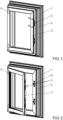
- Figure 1 shows a window with a frame 1 and a main sash 2 located in the frame 1.
- An additional sash 3 is placed on the main sash 2.
- Two fastening units 4 arranged on one long side lock the additional sash 3 to the main sash 2.
- the additional sash 3 is hinged to the main sash 2 via hinges 5.
- Figure 2 shows the window Figure 1 , with the additional wing 3 pivoted away from the main wing 2 about a vertical axis of the hinges 5.
- the fastening units 4 are here in an open position in which the locking elements 6 fastened to the main wing 2 are removed from the other components of the fastening units 4 fastened to the additional wing 3.
- the main wing 2 can also be pivoted or tilted away from the frame 1.
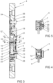
- FIG 3 shows a greatly enlarged longitudinal section through one of the fastening units 4 from Figure 1 along the line III - III.
- the fastening unit 4 has a housing 7 for fastening to the additional wing 3.
- a locking unit 8 and a locking unit 9 for locking the locking unit 8 are arranged in the housing 7.
- the locking unit 8 locks the closure element 6 fastened to the main wing 3 in the housing 7.
- the locking unit 8 has a locking element 11 which is slidably guided in a guide 10. In the locking position shown, the locking element 11 engages behind a locking edge 12 of the closure element 6.
- the locking element 11 penetrates with a projection 14 into a recess 15 of the closure element 6.
- a protruding handle element 13 of the locking element 11 penetrates into an opening 16 of a locking element 17 of the locking unit 9.
- the locking element 17 is pivotally connected to the housing 7 via a bearing 18. Shoulders 19, 20 of the locking element 11 and the locking element 17 are opposite each other so that the locking element 11 cannot be moved.
- the closure element 6 attached to the main wing 2 is therefore firmly held in the housing 7 attached to the additional wing 3.
- the locking element 17 is thus in a locking position in which the movement of the locking element 11 is blocked.
- the locking element 17 is locked to the housing 7 via a locking connection 21.
- a conical guide web 22 is arranged near the free end of the locking element 17.
- the locking element 17 is guided in the housing 7 by the guide web 22.
- a projection 28 at the free end of the locking element 17 enables easy gripping.
- the guide web 22 engages in a fork-shaped recess 23 of the locking element 11 and additionally secures it in its locking position shown.
- the locking element 6 has two locking edges 12, 12', only one of which is opposite the projection 14 of the locking element. This allows the fastening unit 4 to be fastened optionally in right- and left-hinged attachment wings 3.
- the housing 7 has a base plate 24 with the guide 10 for the locking element 11.
- the housing 7 also has a bearing plate 25 for the bearing 18 of the locking element 17.
- the bearing plate 25 and the base plate 24 are kept at a distance from one another by a housing body 26. Rivet connections 27 connect the components of the housing 7 to one another.
- Figure 4 shows a cross section through the fastening unit 4 from Figure 3 along the line IV-IV. It can be seen that the projection 14 of the locking element 11 is surrounded in a U-shape by the closure element 6.
- Figure 5 shows a cross section through the fastening unit 4 from Figure 3 along the line VV through the latching connection 21 of the locking element 17 with the housing 7.
- a latching hook 29 arranged on the housing 7 penetrates into an opening 30 of the locking element 17 and engages behind a latching lug 31 of the locking element 17.
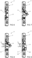
- Figure 6 shows the fastening unit 4 from Figure 3 in a perspective view.
- the locking element 17 lies flat on the housing 7.
- the locking element 17 must first be removed from the Locking element 11 can be swung away. This position is in Figure 7 This releases the movement of the locking element 11.
- the locking element 11 can then be moved in the Figure 3 shown guide 10 and moved with the projection 14 out of the movement range of the locking edge 12 of the closure element 6. This enables the removal of the closure element 6 from the housing 7, as shown in Figure 8
- the auxiliary wing 3 can then be pivoted away from the main wing 2, as shown in Figure 2
- the closing, locking and blocking of the front wing 3 is carried out in reverse order.
Landscapes
- Engineering & Computer Science (AREA)
- Structural Engineering (AREA)
- Civil Engineering (AREA)
- Architecture (AREA)
- Mechanical Engineering (AREA)
- Casings For Electric Apparatus (AREA)
- Hinges (AREA)
Abstract
Description
- Die Erfindung betrifft ein Fenster oder Fenstertür mit einem auf einem Hauptflügel aufgesetzten Vorsatzflügel, mit einer Befestigungseinheit zur lösbaren Verbindung des Vorsatzflügels mit dem Hauptflügel, mit einem an einem der Flügel angeordneten Verschlusselement und ein an dem anderen der Flügel angeordnetes Arretiereinheit der Befestigungseinheit, wobei die Arretiereinheit zwischen einer mit dem Verschlusselement formschlüssig verbundenen Arretierstellung und einer von dem Verschlusselement getrennten Offenstellung bewegbar ist.
- Vorsatzflügel werden bei heutigen Fenstern und Fenstertüren eingesetzt, um beispielsweise einen Bauraum für Jalousien oder dgl. zu schaffen. Die Vorsatzflügel werden in der Regel auf der Außenseite des Hauptflügels angeordnet, so dass der Hauptflügel wie bei einem gewöhnlichen Fenster zu öffnen ist. Damit ist der Vorsatzflügel Windkräften ausgesetzt und dessen Verbindung mit dem Hauptflügel nur schwer zu überwachen.
- Ein Verbundfenster mit auf einem Flügelrahmen aufgesetzten Vorsatzflügel ist beispielsweise aus der
DE 101 38 731 A1 bekannt. Der Vorsatzflügel umfasst eine einfache Glasscheibe, auf die dünne Metallblechstreifen aufgeklebt sind. Der Vorsatzflügel ist auf einer Seite mittels Scharniere und auf der gegenüberliegenden Seite mittels Befestigungsgliedermit dem Flügelrahmen verbunden. Die Befestigungsglieder haben vollständig hinter dem Metallblechstreifen angeordnete Schwenkriegel. Nachteilig bei dem Verbundfenster ist, dass die sichere Verriegelung des Vorsatzflügels an dem Flügelrahmen nur schwer zu kontrollieren oder zu überwachen ist. - Ein Fenster mit einem Fensterflügel und einer auf dem Fensterflügel aufgesetzten Zusatzscheibe ist aus der
DE 299 20 400 U1 bekannt. Bei diesem Fenster sind auf einer Seite des Fensterflügels Scharniere und auf der anderen Seite öffenbare Feststellelemente angeordnet. Die Feststellelemente durchdringen Bohrungen in der Zusatzscheibe. Hierdurch sind Zusatzscheibe und Fensterflügel miteinander verbunden. Die sichere Befestigung der Zusatzscheibe lässt sich jedoch nur schwer kontrollieren oder überwachen. - Der Erfindung liegt das Problem zugrunde, ein Fenster oder Fenstertür der eingangs genannten Art so zu gestalten, dass es möglichst einfach aufgebaut ist und eine dauerhafte und sichere Befestigung des Vorsatzflügels an dem Hauptflügel ermöglicht.
- Dieses Problem wird erfindungsgemäß dadurch gelöst, dass eine Verriegelungseinheit die Arretiereinheit in der Arretierstellung verriegelt.
- Durch diese Gestaltung wird die Verbindung des Vorsatzflügels mit dem Hauptflügel über die Arretiereinheit sichergestellt. Die Arretiereinheit ist in der Arretierstellung jedoch zusätzlich von der Verriegelungseinheit gesichert. Hierdurch wird die Verbindung des Vorsatzflügels mit dem Hauptflügel dauerhaft gesichert. Im einfachsten Fall lässt sich die zuverlässige Befestigung des Vorsatzflügels an dem Hauptflügel durch die Stellung der Verriegelungseinheit erkennen und überwachen.
- Die formschlüssige Verbindung der Flügel in der Arretierstellung gestaltet sich gemäß einer anderen vorteilhaften Weiterbildung der Erfindung besonders einfach, wenn die Arretiereinheit ein bewegliches Arretierelement hat und wenn das Arretierelement in der Arretierstellung eine Sperrkante des Verschlusselements hintergreift.
- Große Freiheitsgrade bei der Montage der Befestigungseinheit lassen sich gemäß einer anderen vorteilhaften Weiterbildung der Erfindung erreichen, wenn das Verschlusselement zwei Sperrkanten aufweist und wenn die Arretiereinheit wahlweise der einen Sperrkante oder der anderen Sperrkante zugewandt montierbar ist. Durch diese Gestaltung ist die Befestigungseinheit ohne weiter Bauteile für rechts und links anschlagende Vorsatzflügel geeignet.
- Die Verriegelungseinheit gestaltet sich gemäß einer anderen vorteilhaften Weiterbildung der Erfindung konstruktiv besonders einfach, wenn die Verriegelungseinheit ein zwischen einer die Arretiereinheit verriegelnde Verriegelungsstellung und einer die Arretiereinheit freigebende Offenstellung bewegliches Verriegelungselement hat.
- Der bauliche Aufwand zur Blockierung der Bewegung des Arretierelements lässt sich gemäß einer anderen vorteilhaften Weiterbildung der Erfindung besonders gering halten, wenn das Verriegelungselement und das Arretierelement in der Verriegelungsstellung einander gegenüberstehende Absätze aufweisen.
- Eine Fehlfunktion der Arretiereinheit und der Verriegelungseinheit lässt sich gemäß einer anderen vorteilhaften Weiterbildung der Erfindung einfach vermeiden, wenn bei in Offenstellung befindlichem Arretierelement die Bewegung des Verriegelungselementes in die Verriegelungsstellung blockiert ist. Hierdurch ist die Reihenfolge der Bedienung der Befestigungseinheit festgelegt, so dass die Verriegelungseinheit erst in die Verriegelungsstellung bewegt werden kann, wenn die Arretiereinheit in die Arretierstellung bewegt ist. Im einfachsten Fall stehen die Absätze des Arretierelements und des Verriegelungselements derart gegenüber, dass diese nur in der Arretierstellung zueinander passen.
- Die Arretiereinheit ist gemäß einer anderen vorteilhaften Weiterbildung der Erfindung konstruktiv besonders einfach aufgebaut, wenn das Arretierelement ein Griffelement zu seiner Bewegung hat und wenn der Absatz des Arretierelements auf dem Griffelement angeordnet ist.
- Das Verriegelungselement lässt sich gemäß einer anderen vorteilhaften Weiterbildung der Erfindung nur in der einen Arretierstellung in die vorgesehene Position gegenüber dem Arretierelement bewegen, wenn das Verriegelungselement eine Öffnung für das Griffelement hat und wenn der Vorsprung des Verriegelungselementes am Rand der Öffnung angeordnet ist. Weiterhin umschließt in der Verriegelungsstellung des Verriegelungselementes die Öffnung das Griffelement, so dass es nicht mehr gegriffen oder bewegt werden kann. Dies trägt zur weiteren Erhöhung der Sicherung der Befestigungseinheit gegen Fehlbedienung bei.
- Die Montage der Befestigungseinheit gestaltet sich gemäß einer anderen vorteilhaften Weiterbildung der Erfindung besonders einfach, wenn die Befestigungseinheit ein an dem Vorsatzflügel oder dem Hauptflügel befestigtes Gehäuse zur Führung des Arretierelements und des Verriegelungselements hat.
- Die Erzeugung eines besonders zuverlässigen Formschlusses zwischen Arretierelement und Verriegelungselement gestaltet sich gemäß einer anderen vorteilhaften Weiterbildung der Erfindung besonders einfach, wenn eines der Bauteile des Arretierelements oder des Verriegelungselementes schwenkbar in dem Gehäuse gelagert ist und das andere Bauteil in dem Gehäuse verschiebbar geführt ist. Diese Gestaltung ermöglicht zudem eine besonders kompakte Bauweise der Befestigungseinheit bei quer zueinander bewegbaren Arretierelement und Verriegelungselement.
- Die Befestigungseinheit lässt sich gemäß einer anderen vorteilhaften Weiterbildung der Erfindung mit einer hohen Stabilität und geringen Materialkosten fertigen, wenn das Gehäuse eine Lagerplatte für eine Lagerung und eine Grundplatte für eine Führung der Bauteile des Arretierelements und des Verriegelungselements aufweisen und wenn zwischen Lagerplatte und Grundplatte ein Gehäusekörper angeordnet ist. Durch diese Gestaltung können Lagerplatte und Grundplatte aus Metall und der Gehäusekörper aus Kunststoff gefertigt werden.
- Das Verriegelungselement wird gemäß einer anderen vorteilhaften Weiterbildung der Erfindung zuverlässig in der Lage gehalten, in der die Flügel miteinander verbunden sind, wenn das Verriegelungselement eine Rastverbindung mit dem Gehäuse in der Verriegelungsstellung hat.
- Der Vorsatzflügel könnte beispielsweise ausschließlich über Befestigungseinheiten mit dem Hauptflügel verbunden sein. Die Handhabung des Vorsatzflügels gestaltet sich jedoch gemäß einer anderen vorteilhaften Weiterbildung der Erfindung besonders einfach, wenn Vorsatzflügel und Hauptflügel an einer Seite über die zumindest eine Befestigungseinheit und auf der gegenüberliegenden Seite über zumindest ein Scharnier miteinander verbunden sind. Durch diese Gestaltung lässt sich der Vorsatzflügel von dem Hauptflügel wegschwenken. Die Anzahl der zu montierenden Befestigungseinheiten richtet sich nach der Größe und dem Gewicht des Vorsatzflügels.
- Die Erfindung lässt zahlreiche Ausführungsformen zu. Zur weiteren Verdeutlichung ihres Grundprinzips sind mehrere davon in der Zeichnung dargestellt und werden nachfolgend beschrieben. Diese zeigt in
- Fig. 1
- ein Fenster mit einem in einem Hauptflügel arretierten Vorsatzflügel,
- Fig. 2
- das Fenster aus
Figur 1 mit von dem Hauptflügel entfernten Vorsatzflügel, - Fig. 3
- vergrößert eine Schnittdarstellung durch eine Befestigungseinheit des Vorsatzflügels aus
Figur 1 entlang der Linie III - III, - Fig. 4
- eine Schnittdarstellung durch die Befestigungseinheit aus
Figur 3 entlang der Linie IV-IV, - Fig. 5
- eine Schnittdarstellung durch die Befestigungseinheit aus
Figur 3 entlang der Linie V-V, - Fig.6
- perspektivisch die Befestigungseinheit mit arretierter Arretiereinheit und verriegelter Verriegelungseinheit,
- Fig.7
- die Befestigungseinheit aus
Figur 6 nach einer Entriegelung der Verriegelungseinheit, - Fig.8
- die Befestigungseinheit aus
Figur 6 in jeweils in Offenstellung befindlicher Arretiereinheit und Verriegelungseinheit, - Fig. 9
- die Befestigungseinheit aus
Figur 6 bei einer versuchten Fehlbedienung. -
Figur 1 zeigt ein Fenster mit einem Rahmen 1 und einem im Rahmen 1 liegenden Hauptflügel 2. Auf dem Hauptflügel 2 ist ein Vorsatzflügel 3 aufgesetzt. Zwei an einer Längsseite angeordnete Befestigungseinheiten 4 arretieren den Vorsatzflügel 3 mit dem Hauptflügel 2. An der gegenüberliegenden Längsseite ist der Vorsatzflügel 3 über Scharniere 5 an dem Hauptflügel 2 angelenkt. -
Figur 2 zeigt das Fenster ausFigur 1 , bei von dem Hauptflügel 2 um eine vertikale Achse der Scharniere 5 weggeschwenkten Vorsatzflügel 3. Die Befestigungseinheiten 4 befinden sich hier in einer Offenstellung, in der am Hauptflügel 2 befestigte Verschlusselemente 6 von den übrigen am Vorsatzflügel 3 befestigten Bauteilen der Befestigungseinheiten 4 entfernt sind. In einer nicht dargestellten Stellung kann auch der Hauptflügel 2 von dem Rahmen 1 weggeschwenkt oder gekippt sein. -
Figur 3 zeigt stark vergrößert einen Längsschnitt durch eine der Befestigungseinheiten 4 ausFigur 1 entlang der Linie III - III. Die Befestigungseinheit 4 hat ein Gehäuse 7 zur Befestigung an dem Vorsatzflügel 3. In dem Gehäuse 7 ist eine Arretiereinheit 8 und eine Verriegelungseinheit 9 zur Verriegelung der Arretiereinheit 8 angeordnet. Die Arretiereinheit 8 arretiert das am Hauptflügel 3 befestigte Verschlusselement 6 im Gehäuse 7. Die Arretiereinheit 8 hat einen in einer Führung 10 verschieblich geführtes Arretierelement 11. Das Arretierelement 11 hintergreift in der dargestellten Arretierstellung eine Sperrkante 12 des Verschlusselementes 6. Dabei dringt das Arretierelement 11 mit einem Vorsprung 14 in eine Ausnehmung 15 des Verschlusselements 6 ein. Ein hervorstehendes Griffelement 13 des Arretierelements 11 dringt in eine Öffnung 16 eines Verriegelungselements 17 der Verriegelungseinheit 9 ein. Das Verriegelungselement 17 ist über eine Lagerung 18 schwenkbar an dem Gehäuse 7 angelenkt. Absätze 19, 20 des Arretierelements 11 und des Verriegelungselements 17 stehen einander gegenüber, so dass das Arretierelement 11 nicht verschoben werden kann. Das am Hauptflügel 2 befestigte Verschlusselement 6 ist daher fest in dem am Vorsatzflügel 3 befestigten Gehäuse 7 gehalten. Damit befindet sich das Verriegelungselement 17 in einer Verriegelungsstellung, in der die Bewegung des Arretierelements 11 blockiert ist. Das Verriegelungselement 17 ist über eine Rastverbindung 21 mit dem Gehäuse 7 verrastet. Nahe des freien Endes des Verriegelungselements 17 ist ein konisch gestalteter Führungssteg 22 angeordnet. Mit dem Führungssteg 22 ist das Verriegelungselements 17 in dem Gehäuse 7 geführt. Ein Vorsprung 28 am freien Ende des Verriegelungselements 17 ermöglicht ein einfaches Greifen. Weiterhin greift der Führungssteg 22 in eine gabelförmig gestaltete Einbuchtung 23 des Arretierelements 11 ein und sichert dieses zusätzlich in seiner dargestellten Arretierstellung. - Weiterhin zeigt
Figur 3 , dass das Verschlusselement 6 zwei Sperrkanten 12, 12` hat, von denen nur eine dem Vorsprung 14 des Arretierelements gegenübersteht. Hierdurch lässt sich die Befestigungseinheit 4 wahlweise in rechts und links anschlagenden Vorsatzflügeln 3 befestigen. - Das Gehäuse 7 hat eine Grundplatte 24 mit der Führung 10 für das Arretierelement 11. Weiterhin hat das Gehäuse 7 eine Lagerplatte 25 für die Lagerung 18 des Verriegelungselements 17. Lagerplatte 25 und Grundplatte 24 sind von einem Gehäusekörper 26 auf Abstand zueinander gehalten. Nietverbindungen 27 verbinden die Bauteile des Gehäuses 7 miteinander.
-
Figur 4 zeigt einen Querschnitt durch die Befestigungseinheit 4 ausFigur 3 entlang der Linie IV-IV. Hierbei ist zu erkennen, dass der Vorsprung 14 des Arretierelements 11 von dem Verschlusselement 6 U-förmig umgriffen ist. -
Figur 5 zeigt einen Querschnitt durch die Befestigungseinheit 4 ausFigur 3 entlang der Linie V-V durch die Rastverbindung 21 des Verriegelungselements 17 mit dem Gehäuse 7. Ein am Gehäuse 7 angeordneter Rasthaken 29 dringt in eine Öffnung 30 des Verriegelungselements 17 ein und hintergreift eine Rastnase 31 des Verriegelungselements 17. -
Figur 6 zeigt die Befestigungseinheit 4 ausFigur 3 in einer perspektivischen Darstellung. Das Verriegelungselement 17 liegt flach auf dem Gehäuse 7 auf. Zum Entfernen des inFigur 1 dargestellten Vorsatzflügels 3 von dem Hauptflügel 2 muss zunächst das Verriegelungselement 17 von dem Arretierelement 11 weggeschwenkt werden. Diese Stellung ist inFigur 7 dargestellt. Hierdurch ist die Bewegung des Arretierelements 11 freigegeben. Das Arretierelement 11 kann anschließend in der inFigur 3 dargestellten Führung 10 verschoben werden und mit dem Vorsprung 14 aus dem Bewegungsbereich der Sperrkante 12 des Verschlusselementes 6 heraus bewegt werden. Dies ermöglicht die Entfernung des Verschlusselementes 6 aus dem Gehäuse 7, wie es inFigur 8 dargestellt ist. Der Vorsatzflügel 3 kann anschließend von dem Hauptflügel 2 weggeschwenkt werden, wie es inFigur 2 dargestellt ist. Das Schließen, Arretieren und Blockieren des Vorsatzflügels 3 erfolgt in umgekehrter Reihenfolge. Versucht man jedoch bei in Offenstellung befindlichen Arretierelement 11 das Verriegelungselement 17 gegen das Gehäuse 7 zu drücken, wie es inFigur 9 dargestellt ist, gelangt der Führungssteg 22 des Verriegelungselements 17 gegen das Griffelement 13 des Arretierelements 11. Eine unerwünschte Bewegung des Verriegelungselementes 7 gegen das Gehäuse 7 wird hierdurch verhindert.
Claims (13)
- Fenster oder Fenstertür mit einem auf einem Hauptflügel (2) aufgesetzten Vorsatzflügel (3), mit einer Befestigungseinheit (4) zur lösbaren Verbindung des Vorsatzflügels (3) mit dem Hauptflügel (2), mit einem an einem der Flügel (2) angeordneten Verschlusselement (6) und ein an dem anderen der Flügel (3) angeordnetes Arretiereinheit (8) der Befestigungseinheit (4), wobei die Arretiereinheit (8) zwischen einer mit dem Verschlusselement (6) formschlüssig verbundenen Arretierstellung und einer von dem Verschlusselement (6) getrennten Offenstellung bewegbar ist, dadurch gekennzeichnet, dass eine Verriegelungseinheit (9) die Arretiereinheit (8) in der Arretierstellung verriegelt.
- Fenster nach Anspruch 1, dadurch gekennzeichnet, dass die Arretiereinheit (8) ein bewegliches Arretierelement (11) hat und dass das Arretierelement (11) in der Arretierstellung eine Sperrkante (12) des Verschlusselements (6) hintergreift.
- Fenster nach Anspruch 2, dadurch gekennzeichnet, dass das Verschlusselement (6) zwei Sperrkanten (12, 12`) aufweist und dass die Arretiereinheit (8) wahlweise der einen Sperrkante (12, 12`) oder der anderen Sperrkante (12, 12`) zugewandt montierbar ist.
- Fenster nach zumindest einem der Ansprüche 1 bis 3, dadurch gekennzeichnet, dass die Verriegelungseinheit (9) ein zwischen einer die Arretiereinheit (8) verriegelnde Verriegelungsstellung und einer die Arretiereinheit (8) freigebende Offenstellung bewegliches Verriegelungselement (17) hat.
- Fenster nach Anspruch 4, dadurch gekennzeichnet, dass das Verriegelungselement (17) und das Arretierelement (11) in der Verriegelungsstellung einander gegenüberstehende Absätze (19, 20) aufweisen.
- Fenster nach Anspruch 4 oder 5, dadurch gekennzeichnet, dass bei in Offenstellung befindlichem Arretierelement (11) die Bewegung des Verriegelungselementes (17) in die Verriegelungsstellung blockiert ist.
- Fenster nach zumindest einem der Ansprüche 2 bis 6, dadurch gekennzeichnet, dass das Arretierelement (11) ein Griffelement (13) zu seiner Bewegung hat und dass der Absatz (20) des Arretierelements (11) auf dem Griffelement (13) angeordnet ist.
- Fenster nach Anspruch 7, dadurch gekennzeichnet, dass das Verriegelungselement (17) eine Öffnung (16) für das Griffelement (13) hat und dass der Vorsprung (19) des Verriegelungselementes (17) am Rand der Öffnung (16) angeordnet ist.
- Fenster nach zumindest einem der Ansprüche 4 bis 8, dadurch gekennzeichnet, dass die Befestigungseinheit (4) ein an dem Vorsatzflügel (3) oder dem Hauptflügel befestigtes Gehäuse (7) zur Führung des Arretierelements (11) und des Verriegelungselements (17) hat.
- Fenster nach Anspruch 9, dadurch gekennzeichnet, dass eines der Bauteile des Arretierelements (11) oder des Verriegelungselementes (17) schwenkbar in dem Gehäuse (7) gelagert ist und das andere Bauteil in dem Gehäuse (7) verschiebbar geführt ist.
- Fenster nach Anspruch 9 oder 10, dadurch gekennzeichnet, dass das Gehäuse (7) eine Lagerplatte (25) für eine Lagerung (18) und eine Grundplatte (24) für eine Führung (10) der Bauteile des Arretierelements (11) und des Verriegelungselements (17) aufweisen und dass zwischen Lagerplatte (25) und Grundplatte (24) ein Gehäusekörper (26) angeordnet ist.
- Fenster nach zumindest einem der Ansprüche 9 bis 11, dadurch gekennzeichnet, dass das Verriegelungselement (17) eine Rastverbindung (21) mit dem Gehäuse (7) in der Verriegelungsstellung hat.
- Fenster nach zumindest einem der Ansprüche 1 bis 12, dadurch gekennzeichnet, dass Vorsatzflügel (3) und Hauptflügel (2) an einer Seite über die zumindest eine Befestigungseinheit (4) und auf der gegenüberliegenden Seite über zumindest ein Scharnier (5) miteinander verbunden sind.
Applications Claiming Priority (1)
| Application Number | Priority Date | Filing Date | Title |
|---|---|---|---|
| DE102023202751.8A DE102023202751A1 (de) | 2023-03-27 | 2023-03-27 | Fenster oder Fenstertür mit einem auf einem Hauptflügel aufgesetzten Vorsatzflügel |
Publications (2)
| Publication Number | Publication Date |
|---|---|
| EP4446533A1 true EP4446533A1 (de) | 2024-10-16 |
| EP4446533B1 EP4446533B1 (de) | 2025-09-10 |
Family
ID=90368662
Family Applications (1)
| Application Number | Title | Priority Date | Filing Date |
|---|---|---|---|
| EP24164522.5A Active EP4446533B1 (de) | 2023-03-27 | 2024-03-19 | Fenster oder fenstertür mit einem auf einem hauptflügel aufgesetzten vorsatzflügel |
Country Status (3)
| Country | Link |
|---|---|
| EP (1) | EP4446533B1 (de) |
| DE (1) | DE102023202751A1 (de) |
| PL (1) | PL4446533T3 (de) |
Citations (7)
| Publication number | Priority date | Publication date | Assignee | Title |
|---|---|---|---|---|
| DE962043C (de) * | 1947-08-18 | 1957-04-18 | Gretsch Unitas Gmbh | Kupplung fuer Verbundfluegel von-Fenstern od. dgl. |
| DE1030729B (de) * | 1955-09-02 | 1958-05-22 | Erich Moehrle | Kupplung fuer Doppelfensterrahmen |
| DE1271593B (de) * | 1966-02-24 | 1968-06-27 | Eugen Notter O H G | Kuppelbeschlag fuer Verbundfluegel von Fenster, Tueren od. dgl. |
| SE325211B (de) * | 1968-10-16 | 1970-06-22 | Nils Karl Thorvald Rundgren Me | |
| DE29920400U1 (de) | 1999-11-20 | 2000-02-10 | Sorpetaler Fensterbau GmbH, 59846 Sundern | Fenster |
| DE10138731A1 (de) | 2001-08-07 | 2003-03-06 | Aug Guttendoerfer Gmbh & Co | Verbund-Fenster oder -Tür |
| DE202015105127U1 (de) * | 2015-09-29 | 2016-12-30 | Burg-Wächter Kg | Fenster- und/oder Türsicherung |
-
2023
- 2023-03-27 DE DE102023202751.8A patent/DE102023202751A1/de active Pending
-
2024
- 2024-03-19 EP EP24164522.5A patent/EP4446533B1/de active Active
- 2024-03-19 PL PL24164522.5T patent/PL4446533T3/pl unknown
Patent Citations (7)
| Publication number | Priority date | Publication date | Assignee | Title |
|---|---|---|---|---|
| DE962043C (de) * | 1947-08-18 | 1957-04-18 | Gretsch Unitas Gmbh | Kupplung fuer Verbundfluegel von-Fenstern od. dgl. |
| DE1030729B (de) * | 1955-09-02 | 1958-05-22 | Erich Moehrle | Kupplung fuer Doppelfensterrahmen |
| DE1271593B (de) * | 1966-02-24 | 1968-06-27 | Eugen Notter O H G | Kuppelbeschlag fuer Verbundfluegel von Fenster, Tueren od. dgl. |
| SE325211B (de) * | 1968-10-16 | 1970-06-22 | Nils Karl Thorvald Rundgren Me | |
| DE29920400U1 (de) | 1999-11-20 | 2000-02-10 | Sorpetaler Fensterbau GmbH, 59846 Sundern | Fenster |
| DE10138731A1 (de) | 2001-08-07 | 2003-03-06 | Aug Guttendoerfer Gmbh & Co | Verbund-Fenster oder -Tür |
| DE202015105127U1 (de) * | 2015-09-29 | 2016-12-30 | Burg-Wächter Kg | Fenster- und/oder Türsicherung |
Also Published As
| Publication number | Publication date |
|---|---|
| DE102023202751A1 (de) | 2024-10-02 |
| EP4446533B1 (de) | 2025-09-10 |
| PL4446533T3 (pl) | 2026-02-09 |
Similar Documents
| Publication | Publication Date | Title |
|---|---|---|
| EP3417134B1 (de) | Beschlaganordnung zur anbindung eines schieb- und kippbaren flügels | |
| DE202012101391U1 (de) | Flügelseitiger Drehflügeltürantriebsanschluss, soweit damit versehene Drehflügeltürantriebsvorrichtung und Drehflügel | |
| EP2113624B1 (de) | Tür- oder Fenstersicherungsvorrichtung | |
| EP4446533B1 (de) | Fenster oder fenstertür mit einem auf einem hauptflügel aufgesetzten vorsatzflügel | |
| DE202013000236U1 (de) | Riegelvorrichtung für eine Schiebetür | |
| DE102008007095B4 (de) | Dreh-Kipp-Beschlag | |
| EP2754804B1 (de) | Verschluss für einen Treibstangenbeschlag | |
| EP2039865A1 (de) | Tor | |
| DE202011000675U1 (de) | Schrank, insbesondere Gasflaschenschrank | |
| DE102005056151B4 (de) | Ecklageranordnung für Fenster, Türen oder dergleichen | |
| EP1344882B1 (de) | Verschluss für Kühlräume | |
| DE202008004659U1 (de) | Öffnungsbegrenzung für ein Fenster oder eine Tür | |
| EP0500125B1 (de) | Verschluss für Fenster oder Türen | |
| EP3141681B1 (de) | Ausstellvorrichtung eines gegen einen rahmen schwenkbaren flügels | |
| DE102014111131A1 (de) | Vorrichtung zur Ver- und Entriegelung eines Fensterflügels, einer Lüftungsklappe oder dergleichen an einem Blendrahmen | |
| EP1498563B1 (de) | Spaltlüftungsvorrichtung | |
| DE102019007009A1 (de) | Ausstellvorrichtung für einen Dreh-Kipp-Flügel eines Fensters oder einer Tür | |
| DE38998C (de) | Selbsttätiger Hakenverschlufs für zweiflügelige Thüren und Fenster | |
| DE102007002014B4 (de) | Sicherheitskippsteller für Fenster oder Türen | |
| AT505570B1 (de) | Zarge mit falz für zumindest einen flügel | |
| DE202007011699U1 (de) | Setzholzfreies Fenster, Tür o.dgl. mit bewegbarem Schließstück | |
| DE102008021283A1 (de) | Sicherung für Türen, Fenster und dergleichen gegen Einbruch | |
| EP3382130B1 (de) | Verriegelungseinheit und fenster oder türe mit einer solchen verriegelungseinheit | |
| DE202020000395U1 (de) | Beschlagsystem für Lüftungsklappen, Lüftungsflügel und dergleichen | |
| DE102024207026A1 (de) | Beschlaganordnung mit einem Zusatzriegel, insbesondere für zweiflüglige Fenster oder Türen ohne mittigen Setzpfosten |
Legal Events
| Date | Code | Title | Description |
|---|---|---|---|
| PUAI | Public reference made under article 153(3) epc to a published international application that has entered the european phase |
Free format text: ORIGINAL CODE: 0009012 |
|
| STAA | Information on the status of an ep patent application or granted ep patent |
Free format text: STATUS: THE APPLICATION HAS BEEN PUBLISHED |
|
| AK | Designated contracting states |
Kind code of ref document: A1 Designated state(s): AL AT BE BG CH CY CZ DE DK EE ES FI FR GB GR HR HU IE IS IT LI LT LU LV MC ME MK MT NL NO PL PT RO RS SE SI SK SM TR |
|
| RAP3 | Party data changed (applicant data changed or rights of an application transferred) |
Owner name: AUG. WINKHAUS SE & CO. KG |
|
| STAA | Information on the status of an ep patent application or granted ep patent |
Free format text: STATUS: REQUEST FOR EXAMINATION WAS MADE |
|
| 17P | Request for examination filed |
Effective date: 20250317 |
|
| GRAP | Despatch of communication of intention to grant a patent |
Free format text: ORIGINAL CODE: EPIDOSNIGR1 |
|
| STAA | Information on the status of an ep patent application or granted ep patent |
Free format text: STATUS: GRANT OF PATENT IS INTENDED |
|
| INTG | Intention to grant announced |
Effective date: 20250429 |
|
| GRAS | Grant fee paid |
Free format text: ORIGINAL CODE: EPIDOSNIGR3 |
|
| GRAA | (expected) grant |
Free format text: ORIGINAL CODE: 0009210 |
|
| STAA | Information on the status of an ep patent application or granted ep patent |
Free format text: STATUS: THE PATENT HAS BEEN GRANTED |
|
| AK | Designated contracting states |
Kind code of ref document: B1 Designated state(s): AL AT BE BG CH CY CZ DE DK EE ES FI FR GB GR HR HU IE IS IT LI LT LU LV MC ME MK MT NL NO PL PT RO RS SE SI SK SM TR |
|
| REG | Reference to a national code |
Ref country code: GB Ref legal event code: FG4D Free format text: NOT ENGLISH |
|
| REG | Reference to a national code |
Ref country code: CH Ref legal event code: EP |
|
| REG | Reference to a national code |
Ref country code: DE Ref legal event code: R096 Ref document number: 502024000217 Country of ref document: DE |
|
| RAP2 | Party data changed (patent owner data changed or rights of a patent transferred) |
Owner name: AUG. WINKHAUS SE |
|
| REG | Reference to a national code |
Ref country code: IE Ref legal event code: FG4D Free format text: LANGUAGE OF EP DOCUMENT: GERMAN |
|
| PG25 | Lapsed in a contracting state [announced via postgrant information from national office to epo] |
Ref country code: NO Free format text: LAPSE BECAUSE OF FAILURE TO SUBMIT A TRANSLATION OF THE DESCRIPTION OR TO PAY THE FEE WITHIN THE PRESCRIBED TIME-LIMIT Effective date: 20251210 |
|
| REG | Reference to a national code |
Ref country code: LT Ref legal event code: MG9D |
|
| PG25 | Lapsed in a contracting state [announced via postgrant information from national office to epo] |
Ref country code: FI Free format text: LAPSE BECAUSE OF FAILURE TO SUBMIT A TRANSLATION OF THE DESCRIPTION OR TO PAY THE FEE WITHIN THE PRESCRIBED TIME-LIMIT Effective date: 20250910 |
|
| REG | Reference to a national code |
Ref country code: NL Ref legal event code: MP Effective date: 20250910 |
|
| PG25 | Lapsed in a contracting state [announced via postgrant information from national office to epo] |
Ref country code: HR Free format text: LAPSE BECAUSE OF FAILURE TO SUBMIT A TRANSLATION OF THE DESCRIPTION OR TO PAY THE FEE WITHIN THE PRESCRIBED TIME-LIMIT Effective date: 20250910 |
|
| PG25 | Lapsed in a contracting state [announced via postgrant information from national office to epo] |
Ref country code: GR Free format text: LAPSE BECAUSE OF FAILURE TO SUBMIT A TRANSLATION OF THE DESCRIPTION OR TO PAY THE FEE WITHIN THE PRESCRIBED TIME-LIMIT Effective date: 20251211 |
|
| PG25 | Lapsed in a contracting state [announced via postgrant information from national office to epo] |
Ref country code: SE Free format text: LAPSE BECAUSE OF FAILURE TO SUBMIT A TRANSLATION OF THE DESCRIPTION OR TO PAY THE FEE WITHIN THE PRESCRIBED TIME-LIMIT Effective date: 20250910 |
|
| PG25 | Lapsed in a contracting state [announced via postgrant information from national office to epo] |
Ref country code: LV Free format text: LAPSE BECAUSE OF FAILURE TO SUBMIT A TRANSLATION OF THE DESCRIPTION OR TO PAY THE FEE WITHIN THE PRESCRIBED TIME-LIMIT Effective date: 20250910 |
|
| PG25 | Lapsed in a contracting state [announced via postgrant information from national office to epo] |
Ref country code: BG Free format text: LAPSE BECAUSE OF FAILURE TO SUBMIT A TRANSLATION OF THE DESCRIPTION OR TO PAY THE FEE WITHIN THE PRESCRIBED TIME-LIMIT Effective date: 20250910 |
|
| PG25 | Lapsed in a contracting state [announced via postgrant information from national office to epo] |
Ref country code: RS Free format text: LAPSE BECAUSE OF FAILURE TO SUBMIT A TRANSLATION OF THE DESCRIPTION OR TO PAY THE FEE WITHIN THE PRESCRIBED TIME-LIMIT Effective date: 20251210 |
|
| PG25 | Lapsed in a contracting state [announced via postgrant information from national office to epo] |
Ref country code: ES Free format text: LAPSE BECAUSE OF FAILURE TO SUBMIT A TRANSLATION OF THE DESCRIPTION OR TO PAY THE FEE WITHIN THE PRESCRIBED TIME-LIMIT Effective date: 20250910 |
|
| PG25 | Lapsed in a contracting state [announced via postgrant information from national office to epo] |
Ref country code: NL Free format text: LAPSE BECAUSE OF FAILURE TO SUBMIT A TRANSLATION OF THE DESCRIPTION OR TO PAY THE FEE WITHIN THE PRESCRIBED TIME-LIMIT Effective date: 20250910 |
|
| PG25 | Lapsed in a contracting state [announced via postgrant information from national office to epo] |
Ref country code: SM Free format text: LAPSE BECAUSE OF FAILURE TO SUBMIT A TRANSLATION OF THE DESCRIPTION OR TO PAY THE FEE WITHIN THE PRESCRIBED TIME-LIMIT Effective date: 20250910 |
|
| PGFP | Annual fee paid to national office [announced via postgrant information from national office to epo] |
Ref country code: DE Payment date: 20260320 Year of fee payment: 3 |
|
| PGFP | Annual fee paid to national office [announced via postgrant information from national office to epo] |
Ref country code: AT Payment date: 20260301 Year of fee payment: 3 |
|
| PGFP | Annual fee paid to national office [announced via postgrant information from national office to epo] |
Ref country code: BE Payment date: 20260323 Year of fee payment: 3 |
|
| PG25 | Lapsed in a contracting state [announced via postgrant information from national office to epo] |
Ref country code: IS Free format text: LAPSE BECAUSE OF FAILURE TO SUBMIT A TRANSLATION OF THE DESCRIPTION OR TO PAY THE FEE WITHIN THE PRESCRIBED TIME-LIMIT Effective date: 20260110 |
|
| PGFP | Annual fee paid to national office [announced via postgrant information from national office to epo] |
Ref country code: FR Payment date: 20260325 Year of fee payment: 3 |
|
| PGFP | Annual fee paid to national office [announced via postgrant information from national office to epo] |
Ref country code: TR Payment date: 20260316 Year of fee payment: 3 |
|
| PG25 | Lapsed in a contracting state [announced via postgrant information from national office to epo] |
Ref country code: CZ Free format text: LAPSE BECAUSE OF FAILURE TO SUBMIT A TRANSLATION OF THE DESCRIPTION OR TO PAY THE FEE WITHIN THE PRESCRIBED TIME-LIMIT Effective date: 20250910 Ref country code: PT Free format text: LAPSE BECAUSE OF FAILURE TO SUBMIT A TRANSLATION OF THE DESCRIPTION OR TO PAY THE FEE WITHIN THE PRESCRIBED TIME-LIMIT Effective date: 20260112 |
|
| PG25 | Lapsed in a contracting state [announced via postgrant information from national office to epo] |
Ref country code: EE Free format text: LAPSE BECAUSE OF FAILURE TO SUBMIT A TRANSLATION OF THE DESCRIPTION OR TO PAY THE FEE WITHIN THE PRESCRIBED TIME-LIMIT Effective date: 20250910 Ref country code: SK Free format text: LAPSE BECAUSE OF FAILURE TO SUBMIT A TRANSLATION OF THE DESCRIPTION OR TO PAY THE FEE WITHIN THE PRESCRIBED TIME-LIMIT Effective date: 20250910 |