EP4445997A1 - Mischlaufrad und aufschlussvorrichtung - Google Patents
Mischlaufrad und aufschlussvorrichtung Download PDFInfo
- Publication number
- EP4445997A1 EP4445997A1 EP24166570.2A EP24166570A EP4445997A1 EP 4445997 A1 EP4445997 A1 EP 4445997A1 EP 24166570 A EP24166570 A EP 24166570A EP 4445997 A1 EP4445997 A1 EP 4445997A1
- Authority
- EP
- European Patent Office
- Prior art keywords
- impeller
- impeller body
- mixing
- overflow hole
- cavity
- Prior art date
- Legal status (The legal status is an assumption and is not a legal conclusion. Google has not performed a legal analysis and makes no representation as to the accuracy of the status listed.)
- Granted
Links
Images
Classifications
-
- B—PERFORMING OPERATIONS; TRANSPORTING
- B01—PHYSICAL OR CHEMICAL PROCESSES OR APPARATUS IN GENERAL
- B01F—MIXING, e.g. DISSOLVING, EMULSIFYING OR DISPERSING
- B01F27/00—Mixers with rotary stirring devices in fixed receptacles; Kneaders
- B01F27/05—Stirrers
- B01F27/11—Stirrers characterised by the configuration of the stirrers
- B01F27/17—Stirrers with additional elements mounted on the stirrer, for purposes other than mixing
- B01F27/171—Stirrers with additional elements mounted on the stirrer, for purposes other than mixing for disintegrating, e.g. for milling
-
- D—TEXTILES; PAPER
- D21—PAPER-MAKING; PRODUCTION OF CELLULOSE
- D21B—FIBROUS RAW MATERIALS OR THEIR MECHANICAL TREATMENT
- D21B1/00—Fibrous raw materials or their mechanical treatment
- D21B1/04—Fibrous raw materials or their mechanical treatment by dividing raw materials into small particles, e.g. fibres
- D21B1/12—Fibrous raw materials or their mechanical treatment by dividing raw materials into small particles, e.g. fibres by wet methods, by the use of steam
- D21B1/30—Defibrating by other means
- D21B1/34—Kneading or mixing; Pulpers
-
- B—PERFORMING OPERATIONS; TRANSPORTING
- B01—PHYSICAL OR CHEMICAL PROCESSES OR APPARATUS IN GENERAL
- B01F—MIXING, e.g. DISSOLVING, EMULSIFYING OR DISPERSING
- B01F27/00—Mixers with rotary stirring devices in fixed receptacles; Kneaders
- B01F27/05—Stirrers
- B01F27/11—Stirrers characterised by the configuration of the stirrers
- B01F27/113—Propeller-shaped stirrers for producing an axial flow, e.g. shaped like a ship or aircraft propeller
- B01F27/1131—Propeller-shaped stirrers for producing an axial flow, e.g. shaped like a ship or aircraft propeller with holes in the propeller blade surface
-
- B—PERFORMING OPERATIONS; TRANSPORTING
- B01—PHYSICAL OR CHEMICAL PROCESSES OR APPARATUS IN GENERAL
- B01F—MIXING, e.g. DISSOLVING, EMULSIFYING OR DISPERSING
- B01F27/00—Mixers with rotary stirring devices in fixed receptacles; Kneaders
- B01F27/05—Stirrers
- B01F27/11—Stirrers characterised by the configuration of the stirrers
-
- B—PERFORMING OPERATIONS; TRANSPORTING
- B01—PHYSICAL OR CHEMICAL PROCESSES OR APPARATUS IN GENERAL
- B01F—MIXING, e.g. DISSOLVING, EMULSIFYING OR DISPERSING
- B01F23/00—Mixing according to the phases to be mixed, e.g. dispersing or emulsifying
- B01F23/50—Mixing liquids with solids
- B01F23/53—Mixing liquids with solids using driven stirrers
-
- B—PERFORMING OPERATIONS; TRANSPORTING
- B01—PHYSICAL OR CHEMICAL PROCESSES OR APPARATUS IN GENERAL
- B01F—MIXING, e.g. DISSOLVING, EMULSIFYING OR DISPERSING
- B01F23/00—Mixing according to the phases to be mixed, e.g. dispersing or emulsifying
- B01F23/50—Mixing liquids with solids
- B01F23/56—Mixing liquids with solids by introducing solids in liquids, e.g. dispersing or dissolving
-
- B—PERFORMING OPERATIONS; TRANSPORTING
- B01—PHYSICAL OR CHEMICAL PROCESSES OR APPARATUS IN GENERAL
- B01F—MIXING, e.g. DISSOLVING, EMULSIFYING OR DISPERSING
- B01F27/00—Mixers with rotary stirring devices in fixed receptacles; Kneaders
- B01F27/05—Stirrers
- B01F27/11—Stirrers characterised by the configuration of the stirrers
- B01F27/117—Stirrers provided with conical-shaped elements, e.g. funnel-shaped
- B01F27/1171—Stirrers provided with conical-shaped elements, e.g. funnel-shaped having holes in the surface
-
- B—PERFORMING OPERATIONS; TRANSPORTING
- B01—PHYSICAL OR CHEMICAL PROCESSES OR APPARATUS IN GENERAL
- B01F—MIXING, e.g. DISSOLVING, EMULSIFYING OR DISPERSING
- B01F27/00—Mixers with rotary stirring devices in fixed receptacles; Kneaders
- B01F27/21—Mixers with rotary stirring devices in fixed receptacles; Kneaders characterised by their rotating shafts
- B01F27/2122—Hollow shafts
-
- B—PERFORMING OPERATIONS; TRANSPORTING
- B01—PHYSICAL OR CHEMICAL PROCESSES OR APPARATUS IN GENERAL
- B01F—MIXING, e.g. DISSOLVING, EMULSIFYING OR DISPERSING
- B01F27/00—Mixers with rotary stirring devices in fixed receptacles; Kneaders
- B01F27/80—Mixers with rotary stirring devices in fixed receptacles; Kneaders with stirrers rotating about a substantially vertical axis
- B01F27/81—Mixers with rotary stirring devices in fixed receptacles; Kneaders with stirrers rotating about a substantially vertical axis the stirrers having central axial inflow and substantially radial outflow
-
- B—PERFORMING OPERATIONS; TRANSPORTING
- B02—CRUSHING, PULVERISING, OR DISINTEGRATING; PREPARATORY TREATMENT OF GRAIN FOR MILLING
- B02C—CRUSHING, PULVERISING, OR DISINTEGRATING IN GENERAL; MILLING GRAIN
- B02C4/00—Crushing or disintegrating by roller mills
- B02C4/10—Crushing or disintegrating by roller mills with a roller co-operating with a stationary member
- B02C4/18—Crushing or disintegrating by roller mills with a roller co-operating with a stationary member in the form of a bar
- B02C4/20—Crushing or disintegrating by roller mills with a roller co-operating with a stationary member in the form of a bar wherein the roller is corrugated or toothed
-
- D—TEXTILES; PAPER
- D21—PAPER-MAKING; PRODUCTION OF CELLULOSE
- D21B—FIBROUS RAW MATERIALS OR THEIR MECHANICAL TREATMENT
- D21B1/00—Fibrous raw materials or their mechanical treatment
- D21B1/04—Fibrous raw materials or their mechanical treatment by dividing raw materials into small particles, e.g. fibres
- D21B1/12—Fibrous raw materials or their mechanical treatment by dividing raw materials into small particles, e.g. fibres by wet methods, by the use of steam
- D21B1/30—Defibrating by other means
- D21B1/34—Kneading or mixing; Pulpers
- D21B1/342—Mixing apparatus
-
- D—TEXTILES; PAPER
- D21—PAPER-MAKING; PRODUCTION OF CELLULOSE
- D21B—FIBROUS RAW MATERIALS OR THEIR MECHANICAL TREATMENT
- D21B1/00—Fibrous raw materials or their mechanical treatment
- D21B1/04—Fibrous raw materials or their mechanical treatment by dividing raw materials into small particles, e.g. fibres
- D21B1/12—Fibrous raw materials or their mechanical treatment by dividing raw materials into small particles, e.g. fibres by wet methods, by the use of steam
- D21B1/30—Defibrating by other means
- D21B1/34—Kneading or mixing; Pulpers
- D21B1/345—Pulpers
-
- D—TEXTILES; PAPER
- D21—PAPER-MAKING; PRODUCTION OF CELLULOSE
- D21B—FIBROUS RAW MATERIALS OR THEIR MECHANICAL TREATMENT
- D21B1/00—Fibrous raw materials or their mechanical treatment
- D21B1/04—Fibrous raw materials or their mechanical treatment by dividing raw materials into small particles, e.g. fibres
- D21B1/12—Fibrous raw materials or their mechanical treatment by dividing raw materials into small particles, e.g. fibres by wet methods, by the use of steam
- D21B1/30—Defibrating by other means
- D21B1/34—Kneading or mixing; Pulpers
- D21B1/345—Pulpers
- D21B1/347—Rotor assemblies
-
- Y—GENERAL TAGGING OF NEW TECHNOLOGICAL DEVELOPMENTS; GENERAL TAGGING OF CROSS-SECTIONAL TECHNOLOGIES SPANNING OVER SEVERAL SECTIONS OF THE IPC; TECHNICAL SUBJECTS COVERED BY FORMER USPC CROSS-REFERENCE ART COLLECTIONS [XRACs] AND DIGESTS
- Y02—TECHNOLOGIES OR APPLICATIONS FOR MITIGATION OR ADAPTATION AGAINST CLIMATE CHANGE
- Y02W—CLIMATE CHANGE MITIGATION TECHNOLOGIES RELATED TO WASTEWATER TREATMENT OR WASTE MANAGEMENT
- Y02W30/00—Technologies for solid waste management
- Y02W30/50—Reuse, recycling or recovery technologies
- Y02W30/64—Paper recycling
Definitions
- the disclosure relates to the technical field of pulping devices, and particularly relates to a mixing impeller and a pulping device.
- a pulping device is widely used in industries such as pharmaceutical, food, and chemical industry, and during a preparation process stage, liquid and solid are fully mixed to obtain a pre-prepared mixture, thereby improving efficiency of subsequent processing.
- dispersion and mixing of solid and liquid are integrated into the same device, and due to an interface between the solid and the liquid is relatively low in an existing structure, the solid and the liquid have a small contact area and a short contact time, thereby causing problems of a low mixing degree of the solid and the liquid and low mixing efficiency, and thus affecting pulping efficiency.
- a mixing impeller includes an impeller body, where the impeller body defines, at a bottom end of the impeller body, a cavity extending to a top end of the impeller body, and the impeller body defines an overflow hole in communication with the cavity at a side wall of the impeller body.
- the disclosure also puts forward a pulping device, the pulping device includes a housing, and the mixing impeller is disposed in the housing.
- mount may include a fixed coupling, a removable coupling, or an integrated coupling; they may include a mechanical coupling or an electrical coupling; they may include a direct coupling, an indirect coupling through a medium, or an interconnection between two components, or an interaction coupling between two components.
- mount may include a fixed coupling, a removable coupling, or an integrated coupling; they may include a mechanical coupling or an electrical coupling; they may include a direct coupling, an indirect coupling through a medium, or an interconnection between two components, or an interaction coupling between two components.
- the disclosure provides a mixing impeller and a pulping device.
- a mixing impeller includes an impeller body, where the impeller body defines, at a bottom end of the impeller body, a cavity extending to a top end of the impeller body, and the impeller body defines an overflow hole in communication with the cavity at a side wall of the impeller body.
- the overflow hole is implemented as multiple overflow holes, the multiple overflow holes are arranged around the side wall of the impeller body at intervals, and the overflow holes are disposed at the side wall close to the top end of the impeller body.
- the overflow hole is inclined from the top end of the impeller body to the bottom end of the impeller body in a direction from an inner wall of the impeller body to an outer wall of the impeller body.
- the impeller body is provided with a baffle above the overflow hole, and the baffle is inclined from the top end of the impeller body to the bottom end of the impeller body.
- the overflow hole is arranged in a radial direction of the impeller body.
- the overflow hole is inclined from the bottom end of the impeller body to the top end of the impeller body in the direction from the inner wall of the impeller body to the outer wall of the impeller body.
- the overflow hole is inclined to the same side from inside to outside as a direction opposite to a rotation direction of the impeller body.
- the overflow hole is a circular hole, an elliptic hole, a polygonal hole, or a flat hole.
- the impeller body includes a cylinder segment and a frustum section smoothly connected to the cylinder segment, the frustum section has a large end connected to the cylinder segment, and the cavity passes through the cylinder segment and extends into the frustum section.
- the overflow hole is defined on a side wall of the frustum section.
- the cavity is an annular cavity, and the annular cavity and the impeller body are disposed coaxially; or the cavity includes multiple sub-cavities arranged at intervals, and multiple sub-cavities cooperatively form the cavity.
- the impeller body is provided with multiple vanes arranged at intervals at the outer wall of impeller body, and at least one overflow hole is defined in an area between two adjacent vanes.
- the impeller body is provided with multiple vanes arranged at intervals at the outer wall of impeller body, and two ends of the baffle abut against vanes at two adjacent sides of the baffle.
- the disclosure also puts forward a pulping device, the pulping device includes a housing, and the mixing impeller is disposed in the housing.
- the impeller body can rotate around its own axis, and during rotation, solid material, such as powder, is transported from top to bottom through an outer flow channel of the impeller body, material is transported from bottom to top through the cavity of the impeller body, and the liquid material flows through the cavity and flows of from the overflow hole defined on the side wall of the impeller body to be mixed with the solid material.
- a liquid level of the liquid material is improved due to the cavity and the overflow hole of the impeller body, so as to improve the height of a mixing interface of the solid material and the liquid material, and further improve the mixing efficiency.
- the overflow hole is disposed on the side wall at the top end of the impeller body.
- the liquid material is transported from bottom to top and flows out of the overflow hole after flowing through the cavity, that is, flows out from the top side wall of the impeller, thereby improving the height of the mixing interface of the solid material and the liquid material.
- Multiple overflow holes are arranged at intervals, and when the impeller body rotates around its own axis, the liquid material in the cavity is thrown out of multiple overflow holes under the action of centrifugal force, so as to disperse the liquid material, and further improve the mixing efficiency of the solid material and the liquid material.
- the overflow hole is inclined from the top end of the impeller body to the bottom end of the impeller body in the direction from the inner wall of the impeller body to the outer wall of the impeller body, and a junction of the solid material and the liquid material forms an inclined plane, thereby increasing a mixing contact area of solid and liquid, improving the mixing efficiency of the solid and the liquid, increasing the downward transporting speed of the solid, reducing the returning possibility of material, so as to enhance the mixing quality of solid and liquid and improve the pulping efficiency.
- a caking caused by mixing of the solid material and the liquid material can also be avoided from blocking the overflow hole and affecting the mixing efficiency.
- the baffle when the overflow hole is inclined from the bottom end of the impeller body to the top end of the impeller body, or when the overflow hole is arranged in the radial direction of the impeller body, the baffle is disposed above the overflow hole, and the baffle is inclined from the top end of the impeller body to the bottom end of the impeller body, so that when the solid material flows from the top to the bottom, under the blocking effect of the baffle, the solid material flows in a direction away from the outer wall of the impeller, so as to avoid affecting the mixing efficiency, caused by blockage of overflow hole due to the caking generated when the solid material and the liquid material are mixed.
- the overflow hole in the direction from the inner wall of the impeller body to the outer wall of the impeller body, the overflow hole is inclined from the bottom end of the impeller body to the top end of the impeller body, thereby improving the height of the mixing interface of the solid material and the liquid material, and further improving the mixing efficiency.
- multiple sub-cavities cooperatively form the cavity, and when the impeller body rotates, the liquid material rotates with the impeller in multiple sub-cavities, and during rotation, the liquid material is dispersed under the action of centrifugal force, so that the liquid material flowing out of the overflow hole is more dispersed, and the mixing efficiency of the solid material and the liquid material is higher.
- At least one overflow hole is defined in an area between two vanes, and the overflow hole is inclined to the same side from inside to outside as a direction opposite to a rotation direction of the impeller body, during rotation of the impeller body around its own axis, the liquid material in the cavity is thrown out of overflow holes under the action of centrifugal force, and is further dispersed after colliding with the vanes, so that the solid material and the liquid material is mixed more uniformly, less caking is generated, and the mixing efficiency is improved.
- the mixing impeller is mounted in the housing, thereby improving the height of the mixing interface of the solid material and the liquid material of the pulping device, increasing a feeding speed, and improving the pulping efficiency.
- the disclosure provides a mixing impeller.
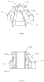
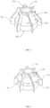
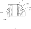
- the mixing impeller includes an impeller body 21, the impeller body 21 defines a cavity 214 extending from the bottom end of the impeller body 21 to the top end of the impeller body 21, and the impeller body 21 defines an overflow hole 213 in communication with the cavity 214 at a side wall of the impeller body 21.
- the impeller body 21 can rotate around its own axis, and during rotation, solid material is transported from top to bottom along an outer flow channel of the impeller body 21, and liquid material is transported from bottom to top through the cavity of the impeller body 21.
- the liquid material flows through the cavity 214 and flows out of the overflow hole 213 defined on the side wall of the impeller body 21 to be mixed with the solid material.
- a liquid level of the liquid material is improved due to the cavity 214 and the overflow hole 213 on the impeller body 21, so as to improve the height of a mixing interface of the solid material and the liquid material, and further improve the mixing efficiency.
- the overflow hole 213 is implemented as multiple overflow holes 213, the multiple overflow holes 213 are arranged around the side wall of the impeller body 21 at intervals, and multiple overflow holes 213 are disposed at the side wall close to a top end of the impeller body 21.
- the overflow hole 213 is disposed on the side wall at the top end of the impeller body 21, and the liquid material is transported from bottom to top and flows out of the overflow hole 213 after flowing through the cavity 214, that is, the liquid material flows out from the top side wall of the impeller, thereby improving the height of the mixing interface of the solid material and the liquid material.
- Multiple overflow holes 213 are arranged at intervals, and when the impeller body 21 rotates around its own axis, the liquid material in the cavity 214 is thrown out of multiple overflow holes 213 under the action of centrifugal force, so as to disperse the liquid material, and further improve the mixing efficiency of the solid material and the liquid material.
- the overflow hole 213 is inclined from the top end of the impeller body 21 to the bottom end of the impeller body 21.
- the overflow hole 213 when the overflow hole 213 is inclined from the top end of the impeller body 21 to the bottom end of the impeller body 21, the liquid material flows downward after the liquid material is thrown out of the overflow hole, and the solid material also flows downward, so that a mixing interface of the solid material and the liquid material forms an inclined surface, thereby increasing a mixing contact area of the solid material and the liquid material, improving the mixing efficiency of the solid material and the liquid material, increasing the downward transporting speed of the solid material, reducing the returning probability of material, and improving the mixing quality of the solid material and the liquid material.
- a caking caused by mixing of the solid material and the liquid material can also be avoided from blocking the overflow hole 213 and affecting the mixing efficiency.
- the impeller body 21 is provided with a baffle 215 above the overflow hole 213, and the baffle 215 is inclined from the top end of the impeller body 21 to the bottom end of the impeller body 21.
- a caking may be generated easily during mixing of the solid material and the liquid material, when the overflow hole 213 is inclined from the bottom end of the impeller body 21 to the top end of the impeller body 21, or when the overflow hole 213 is arranged in a radial direction of the impeller body 21, the solid materials and liquid materials are mixed and in contact at the overflow hole 213, and if the caking is generated and the caking generated is too large, the caking is easy to fall into the overflow hole 213, causing blockage to the overflow hole 213, thus affecting the feeding of the liquid material.
- the impeller body 21 is provided with the baffle 215 above the overflow hole 213, and the baffle 215 is inclined from the top end of the impeller body 21 to the bottom end of the impeller body 21, so that when the solid material flows from top to bottom, under the blocking of the baffle 215, the solid material flows in a direction away from the outer wall of the impeller body 21, avoiding mixing of the solid material and liquid material at the overflow hole 213, thereby avoiding the blockage of the overflow hole 213 caused by the caking generated, and avoiding affecting the mixing efficiency.
- the overflow hole 213 is inclined from the bottom end of the impeller body 21 to the top end of the impeller body 21.
- the overflow hole 213 is inclined from the bottom end of impeller body 21 to the top end of impeller body 21, to further improve the height of the mixing interface of the liquid material and the solid material, thereby improving the mixing quality and increasing the mixing speed.
- the overflow hole 213 is inclined to the same side from inside to outside as a direction opposite to a rotation direction of the impeller body 21.
- the overflow hole 213 is inclined to the same side from inside to outside as the direction opposite to the rotation direction of the impeller body 21.
- the impeller body 21 rotates around its own axis, under the action of the centrifugal force, a direction in which the liquid material flows is the same to that of the centrifugal force, and the liquid material is more easily thrown out of the overflow hole 213, so that the liquid material is dispersed, the higher a dispersion degree of the liquid, the better the quality of mixing with the solid material.
- the overflow hole 213 is arranged in a radial direction of the impeller body 21.
- the overflow hole 213 is a circular hole, an elliptic hole, a polygonal hole, or a flat hole.
- the flat hole facilitates the dispersion of the liquid material, increases the dispersion degree of the liquid material, and improves the mixing quality of the solid material and the liquid material.
- the impeller body 21 includes a cylinder segment 212 and a frustum section 211 smoothly connected to the cylinder segment 212, the frustum section 211 has a large end connected to the cylinder segment 212, and the cavity 214 passes through the cylinder segment 212 and extends into the frustum section 211.
- the overflow hole 213 is defined on a side wall of the frustum section 211.
- the setting of the frustum section 211 facilitates the downward transportation of solid material, and because the side wall of the frustum section 211 is an inclined surface, the feeding speed of solid is increased.
- the cylinder segment 212 is disposed under the frustum segment 211 to increase the height of the impeller body 21.
- the cavity 214 extends through the cylinder segment 212 and the frustum segment 211, and the overflow hole 213 is defined on the side wall of the frustum segment 211 and is connected to the cavity 214.
- the liquid material When the liquid material is transported from bottom to top, the liquid material flows through the cavity 214 and is thrown out of the overflow hole 213 on the side wall of the frustum segment 211 to be mixed with the solid material on the side wall of the frustum segment 211. Because the side wall of the frustum segment 211 is inclined, the mixing interface area of the solid material and the liquid material is increased, the feeding speed is improved, and the mixing efficiency is improved.
- the cavity 214 is a ring cavity, and the ring cavity and the impeller body 21 are disposed coaxially.
- the cavity 214 includes multiple sub-cavities arranged at intervals, and the multiple sub-cavities cooperatively form the cavity 214.
- the cavity 214 serves to provide a temporary storage space for the liquid material, when the impeller body 21 rotates, the liquid material temporarily stored in the cavity 214 can be thrown out of the overflow hole 213 under the action of the centrifugal force, thereby improving the dispersion degree of the liquid material.
- the cavity 214 is a ring cavity, the volume of the cavity 214 is increased, and the liquid material can be fully dispersed when the liquid material flows out, thus improving the mixing quality of the liquid material and the solid material.
- the cavity 214 includes multiple sub-cavities
- the liquid material flows into the multiple sub-cavities from bottom to top, and during the rotation of the impeller body 21, the liquid material can be initially dispersed in the sub-cavities and then dispersed again when the liquid material is thrown out of the overflow hole 213 under the action of the centrifugal force.
- the cavity 214 formed by the multiple sub-cavities can improve the dispersion degree of the liquid material, thereby improving the mixing quality of the solid material and the liquid material and improving the mixing efficiency.
- the impeller body 21 is provided with multiple vanes 22 arranged at intervals at an outer wall of impeller body 21, and at least one overflow hole 213 is defined in an area between two adjacent vanes 22.
- the vane 22 can guide the solid material to be transported downward, a flow channel is defined between two adjacent vanes 22, the solid material is transported in the flow channel from top to bottom, and the overflow hole 213 is defined between two adjacent vanes 22, that is, it is disposed in the flow channel.
- the overflow hole 213 is inclined to the same side from inside to outside as a direction opposite to a rotation direction of the impeller body 21.
- the liquid material in the cavity 214 is thrown out of the overflow holes 213 under the action of the centrifugal force, and is further dispersed after impacting with the vane 22, thereby making the mixing of solid material and liquid material more uniform, reducing the generation of caking, and improving the mixing efficiency.
- the number and apertures of the overflow holes 213 are not considered as limitations to the disclosure.
- the number and apertures of the overflow holes 213 are positively correlated with the flow velocity of the liquid material, and the apertures of the overflow holes 213 are inversely correlated with the dispersion degree of the liquid material.
- the number of overflow holes 213 is greater and the apertures are larger, the flow velocity of the liquid material is faster under a certain pressure of a driving pump.
- the number of the overflow holes 213 is smaller and the apertures are smaller, the flow velocity of the liquid material is slower.
- smaller apertures of the overflow holes 213 may lead to higher dispersion degree of the liquid material. Therefore, specific parameters such as the number and apertures of the overflow holes 213 are selected and determined according to the nature of the liquid material and the pressure of the driving pump.
- the impeller body 21 is provided with multiple vanes 22 arranged at intervals at the outer wall of impeller body 21, and two ends of the baffle 215 abut against vanes 22 at two adjacent sides of the baffle 215.
- the two ends of the baffle 215 may abut against two adjacent vanes 22, or the baffle 215 only covers the aperture of the overflow hole 213, so the width of baffle 215 is not limited in the disclosure.
- the distance between a far end of the baffle 215 and the outer wall of the impeller body 21 should be less than a chord length of the vane 22, so as to avoid affecting feeding efficiency of solid due to excessive accumulation of solids at the baffle 215.
- the disclosure also provides a pulping device.
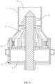
- the pulping device includes a housing 1, and the mixing impeller 2 disposed in the housing 1.
- the housing 1 defines a liquid inlet 11 on a peripheral wall at the bottom of the housing 1.
- the liquid material enters from the liquid inlet 11, the housing 1 is provided with a liquid dispersion device 3 at the bottom the housing 1, the liquid material is dispersed by the liquid dispersion device 3 and flows to the mixing impeller 2.
- the housing 1 defines a solid inlet 12 at the top of the housing 1, the housing 1 is provided with a solid dispersion device 4 at the top of the housing 1, and the solid material is dispersed by the solid dispersion device 4 and flows to the mixing impeller 2.
- the dispersed liquid material enters the cavity 214 from the bottom of the impeller body 21 and is thrown out of the overflow holes 213 under the action of the centrifugal force, and the solid material is transported downward in the outer flow passage of the impeller body 21, after the solid material and the liquid material are fully mixed on the top side wall of the impeller body 21, the mixed solid material and the liquid material flow out of the mixture outlet 13 on the side wall of the housing 1.
- the liquid material enters from the liquid inlet 11, after being dispersed by the dispersion device, the liquid material flows upward under the action of the driving pump, a guide plate is disposed between the liquid dispersion 3 and mixing impeller 2 to make the liquid flow into the cavity 214 of the impeller.
- the solid material flows to the mixing impeller 2 after being dispersed by the solid dispersing device 4, when the mixing impeller 2 rotates, the solid material is transported downward along the flow passage between two adjacent vanes 22 under the guiding downward pressure of the blades 22, and is mixed with the liquid material near the flow hole 213.
- the mixing impeller 2 the height of the mixing interface of the solid material and the liquid material of the pulping device is increased, a feeding speed is increased, and g the pulping efficiency is improved.
Landscapes
- Chemical & Material Sciences (AREA)
- Engineering & Computer Science (AREA)
- Chemical Kinetics & Catalysis (AREA)
- Life Sciences & Earth Sciences (AREA)
- Wood Science & Technology (AREA)
- Mechanical Engineering (AREA)
- Dispersion Chemistry (AREA)
- Food Science & Technology (AREA)
- Aviation & Aerospace Engineering (AREA)
- Mixers Of The Rotary Stirring Type (AREA)
- Paper (AREA)
Priority Applications (1)
| Application Number | Priority Date | Filing Date | Title |
|---|---|---|---|
| MA71470A MA71470B1 (fr) | 2023-03-28 | 2024-03-26 | Roue de mélange et dispositif de réduction en pâte |
Applications Claiming Priority (1)
| Application Number | Priority Date | Filing Date | Title |
|---|---|---|---|
| CN202310370736.7A CN116351272A (zh) | 2023-03-28 | 2023-03-28 | 混合叶轮及制浆设备 |
Publications (2)
| Publication Number | Publication Date |
|---|---|
| EP4445997A1 true EP4445997A1 (de) | 2024-10-16 |
| EP4445997B1 EP4445997B1 (de) | 2025-12-24 |
Family
ID=86908007
Family Applications (1)
| Application Number | Title | Priority Date | Filing Date |
|---|---|---|---|
| EP24166570.2A Active EP4445997B1 (de) | 2023-03-28 | 2024-03-26 | Mischlaufrad und aufschlussvorrichtung |
Country Status (7)
| Country | Link |
|---|---|
| US (1) | US20240325996A1 (de) |
| EP (1) | EP4445997B1 (de) |
| JP (1) | JP7789823B2 (de) |
| KR (1) | KR20240145922A (de) |
| CN (1) | CN116351272A (de) |
| ES (1) | ES3065726T3 (de) |
| MA (1) | MA71470B1 (de) |
Families Citing this family (4)
| Publication number | Priority date | Publication date | Assignee | Title |
|---|---|---|---|---|
| KR20240008893A (ko) | 2021-05-17 | 2024-01-19 | 닛토덴코 가부시키가이샤 | 도막 보호 코트재 및 코팅 조성물 |
| USD1070064S1 (en) * | 2022-01-13 | 2025-04-08 | Delta Electronics, Inc. | Fan blade |
| USD1068058S1 (en) * | 2022-04-27 | 2025-03-25 | Foshan Samyoo Electronic Co., Ltd. | Impeller |
| USD1067419S1 (en) * | 2022-04-27 | 2025-03-18 | Foshan Samyoo Electronic Co., Ltd. | Impeller |
Citations (4)
| Publication number | Priority date | Publication date | Assignee | Title |
|---|---|---|---|---|
| DE879081C (de) * | 1951-02-23 | 1953-06-11 | Michael Philosophow | Ruehrwerk mit Luftzufuehrung |
| CN105457524A (zh) * | 2016-01-07 | 2016-04-06 | 济南多舜信息科技有限公司 | 一种污水处理池 |
| US20170021313A1 (en) * | 2013-12-11 | 2017-01-26 | Invent Umwelt- Und Verfahrenstechnik Ag | Agitating member and agitating device for creating a current in a wastewater treatment basin |
| US20180339277A1 (en) * | 2008-06-16 | 2018-11-29 | Isel Co., Ltd. | Mixing unit and device, and fluid mixing method |
Family Cites Families (11)
| Publication number | Priority date | Publication date | Assignee | Title |
|---|---|---|---|---|
| JPS53148067A (en) * | 1977-05-28 | 1978-12-23 | Kobe Steel Ltd | Pin mixer |
| JPS6033058B2 (ja) * | 1981-06-09 | 1985-07-31 | 松下電器産業株式会社 | 調理機 |
| JP4418019B1 (ja) * | 2009-06-23 | 2010-02-17 | 和久 村田 | 攪拌用回転体および攪拌装置 |
| JP2013111486A (ja) * | 2011-11-24 | 2013-06-10 | Toyota Motor Corp | 粉体吸引型混練装置 |
| CN204685013U (zh) * | 2015-05-14 | 2015-10-07 | 四川海聚环保科技有限责任公司 | 可调粘度的浆料搅拌分散器 |
| CN208553804U (zh) * | 2018-06-22 | 2019-03-01 | 无锡维吉尔机械有限公司 | 搅拌叶轮 |
| CN110394082B (zh) * | 2019-07-31 | 2021-08-13 | 深圳市尚水智能设备有限公司 | 一种叶轮组件及使用该组件的固体和液体混合设备 |
| CN111249941B (zh) * | 2020-02-10 | 2021-09-14 | 深圳市尚水智能设备有限公司 | 一种用于固体在液体中分散的叶轮组件及使用该组件的固液混合设备 |
| US20220347635A1 (en) * | 2021-04-29 | 2022-11-03 | Metso Outotec Finland Oy | Impeller, a diffuser and an arrangement using such impeller and diffuser in a flotation tank |
| CN217042141U (zh) * | 2022-03-01 | 2022-07-26 | 宏工科技股份有限公司 | 一种筒式分散装置 |
| CN116422176B (zh) * | 2023-03-28 | 2025-03-28 | 深圳市尚水智能股份有限公司 | 混合叶轮及制浆设备 |
-
2023
- 2023-03-28 CN CN202310370736.7A patent/CN116351272A/zh active Pending
-
2024
- 2024-03-26 ES ES24166570T patent/ES3065726T3/es active Active
- 2024-03-26 EP EP24166570.2A patent/EP4445997B1/de active Active
- 2024-03-26 MA MA71470A patent/MA71470B1/fr unknown
- 2024-03-27 US US18/618,455 patent/US20240325996A1/en active Pending
- 2024-03-28 KR KR1020240042812A patent/KR20240145922A/ko active Pending
- 2024-03-28 JP JP2024053619A patent/JP7789823B2/ja active Active
Patent Citations (4)
| Publication number | Priority date | Publication date | Assignee | Title |
|---|---|---|---|---|
| DE879081C (de) * | 1951-02-23 | 1953-06-11 | Michael Philosophow | Ruehrwerk mit Luftzufuehrung |
| US20180339277A1 (en) * | 2008-06-16 | 2018-11-29 | Isel Co., Ltd. | Mixing unit and device, and fluid mixing method |
| US20170021313A1 (en) * | 2013-12-11 | 2017-01-26 | Invent Umwelt- Und Verfahrenstechnik Ag | Agitating member and agitating device for creating a current in a wastewater treatment basin |
| CN105457524A (zh) * | 2016-01-07 | 2016-04-06 | 济南多舜信息科技有限公司 | 一种污水处理池 |
Also Published As
| Publication number | Publication date |
|---|---|
| EP4445997B1 (de) | 2025-12-24 |
| MA71470B1 (fr) | 2026-03-31 |
| ES3065726T3 (en) | 2026-05-07 |
| CN116351272A (zh) | 2023-06-30 |
| JP7789823B2 (ja) | 2025-12-22 |
| KR20240145922A (ko) | 2024-10-07 |
| JP2024144369A (ja) | 2024-10-11 |
| US20240325996A1 (en) | 2024-10-03 |
| MA71470A (fr) | 2025-04-30 |
Similar Documents
| Publication | Publication Date | Title |
|---|---|---|
| US20240325996A1 (en) | Mixing Impeller And Pulping Device | |
| CN1024259C (zh) | 搅拌器 | |
| CN116059899B (zh) | 粉液混合设备 | |
| US6402361B1 (en) | Charging assembly for mixing vessel | |
| CN218901577U (zh) | 浆料分散装置 | |
| WO2024192925A1 (zh) | 一种叶轮组件、循环分散机及循环分散系统 | |
| CN1367711A (zh) | 除气离心装置,泵送流体和其除气工艺及生产纸或纸板工艺 | |
| CN108393008A (zh) | 搅拌机构及制浆装置 | |
| US4941752A (en) | Mixing equipment and methods | |
| CN107243288A (zh) | 管道混合装置 | |
| CN111495228A (zh) | 搅拌装置 | |
| CN215539921U (zh) | 一种钛白粉和粉料递进分散装置 | |
| JP2015502846A (ja) | チャンネル状羽根を有する撹拌インペラ | |
| JP2019520207A (ja) | 容器を備える材料を処理するためのデバイス | |
| WO2024198137A1 (zh) | 叶轮组件及制浆设备 | |
| CN114699963B (zh) | 搅拌装置及其应用 | |
| CN219518614U (zh) | 粉液混合设备 | |
| CN116422176A (zh) | 混合叶轮及制浆设备 | |
| US20100214868A1 (en) | Agitator and Agitation Method | |
| WO2024174742A1 (zh) | 粉液混合设备 | |
| CN216395339U (zh) | 一种离心萃取机 | |
| CN219849020U (zh) | 混合叶轮及制浆设备 | |
| CN211358414U (zh) | 药物混合装置 | |
| CN220726597U (zh) | 一种带有扰流板的固液混合离心泵 | |
| EP4491264B1 (de) | Aufschlussvorrichtung |
Legal Events
| Date | Code | Title | Description |
|---|---|---|---|
| PUAI | Public reference made under article 153(3) epc to a published international application that has entered the european phase |
Free format text: ORIGINAL CODE: 0009012 |
|
| STAA | Information on the status of an ep patent application or granted ep patent |
Free format text: STATUS: REQUEST FOR EXAMINATION WAS MADE |
|
| 17P | Request for examination filed |
Effective date: 20240326 |
|
| AK | Designated contracting states |
Kind code of ref document: A1 Designated state(s): AL AT BE BG CH CY CZ DE DK EE ES FI FR GB GR HR HU IE IS IT LI LT LU LV MC ME MK MT NL NO PL PT RO RS SE SI SK SM TR |
|
| RAV | Requested validation state of the european patent: fee paid |
Extension state: MA Effective date: 20250416 |
|
| GRAP | Despatch of communication of intention to grant a patent |
Free format text: ORIGINAL CODE: EPIDOSNIGR1 |
|
| STAA | Information on the status of an ep patent application or granted ep patent |
Free format text: STATUS: GRANT OF PATENT IS INTENDED |
|
| INTG | Intention to grant announced |
Effective date: 20250729 |
|
| RIN1 | Information on inventor provided before grant (corrected) |
Inventor name: BAI, SHUJUAN Inventor name: DU, BAODONG Inventor name: JIN, XUDONG Inventor name: SHI, QIAO Inventor name: ZHANG, WANG |
|
| GRAS | Grant fee paid |
Free format text: ORIGINAL CODE: EPIDOSNIGR3 |
|
| GRAA | (expected) grant |
Free format text: ORIGINAL CODE: 0009210 |
|
| STAA | Information on the status of an ep patent application or granted ep patent |
Free format text: STATUS: THE PATENT HAS BEEN GRANTED |
|
| AK | Designated contracting states |
Kind code of ref document: B1 Designated state(s): AL AT BE BG CH CY CZ DE DK EE ES FI FR GB GR HR HU IE IS IT LI LT LU LV MC ME MK MT NL NO PL PT RO RS SE SI SK SM TR |
|
| REG | Reference to a national code |
Ref country code: CH Ref legal event code: F10 Free format text: ST27 STATUS EVENT CODE: U-0-0-F10-F00 (AS PROVIDED BY THE NATIONAL OFFICE) Effective date: 20251224 Ref country code: GB Ref legal event code: FG4D |
|
| REG | Reference to a national code |
Ref country code: DE Ref legal event code: R096 Ref document number: 602024001779 Country of ref document: DE |
|
| REG | Reference to a national code |
Ref country code: MA Ref legal event code: VAGR Ref document number: 71470 Country of ref document: MA Kind code of ref document: B1 |
|
| REG | Reference to a national code |
Ref country code: LT Ref legal event code: MG9D |
|
| PG25 | Lapsed in a contracting state [announced via postgrant information from national office to epo] |
Ref country code: NO Free format text: LAPSE BECAUSE OF FAILURE TO SUBMIT A TRANSLATION OF THE DESCRIPTION OR TO PAY THE FEE WITHIN THE PRESCRIBED TIME-LIMIT Effective date: 20260324 |
|
| PGFP | Annual fee paid to national office [announced via postgrant information from national office to epo] |
Ref country code: DE Payment date: 20260324 Year of fee payment: 3 |
|
| PG25 | Lapsed in a contracting state [announced via postgrant information from national office to epo] |
Ref country code: FI Free format text: LAPSE BECAUSE OF FAILURE TO SUBMIT A TRANSLATION OF THE DESCRIPTION OR TO PAY THE FEE WITHIN THE PRESCRIBED TIME-LIMIT Effective date: 20251224 Ref country code: HR Free format text: LAPSE BECAUSE OF FAILURE TO SUBMIT A TRANSLATION OF THE DESCRIPTION OR TO PAY THE FEE WITHIN THE PRESCRIBED TIME-LIMIT Effective date: 20251224 |
|
| PGFP | Annual fee paid to national office [announced via postgrant information from national office to epo] |
Ref country code: AT Payment date: 20260301 Year of fee payment: 3 |
|
| VSFP | Annual fee paid to validation state [announced via postgrant information from national office to epo] |
Ref country code: MA Payment date: 20260408 Year of fee payment: 3 |
|
| PG25 | Lapsed in a contracting state [announced via postgrant information from national office to epo] |
Ref country code: RS Free format text: LAPSE BECAUSE OF FAILURE TO SUBMIT A TRANSLATION OF THE DESCRIPTION OR TO PAY THE FEE WITHIN THE PRESCRIBED TIME-LIMIT Effective date: 20260324 |
|
| PGFP | Annual fee paid to national office [announced via postgrant information from national office to epo] |
Ref country code: TR Payment date: 20260325 Year of fee payment: 3 |
|
| PG25 | Lapsed in a contracting state [announced via postgrant information from national office to epo] |
Ref country code: LV Free format text: LAPSE BECAUSE OF FAILURE TO SUBMIT A TRANSLATION OF THE DESCRIPTION OR TO PAY THE FEE WITHIN THE PRESCRIBED TIME-LIMIT Effective date: 20251224 |
|
| REG | Reference to a national code |
Ref country code: NL Ref legal event code: MP Effective date: 20251224 |
|
| PG25 | Lapsed in a contracting state [announced via postgrant information from national office to epo] |
Ref country code: BG Free format text: LAPSE BECAUSE OF FAILURE TO SUBMIT A TRANSLATION OF THE DESCRIPTION OR TO PAY THE FEE WITHIN THE PRESCRIBED TIME-LIMIT Effective date: 20251224 |
|
| REG | Reference to a national code |
Ref country code: ES Ref legal event code: FG2A Ref document number: 3065726 Country of ref document: ES Kind code of ref document: T3 Effective date: 20260507 |