EP4445933A2 - Autoinjektor - Google Patents
Autoinjektor Download PDFInfo
- Publication number
- EP4445933A2 EP4445933A2 EP24197383.3A EP24197383A EP4445933A2 EP 4445933 A2 EP4445933 A2 EP 4445933A2 EP 24197383 A EP24197383 A EP 24197383A EP 4445933 A2 EP4445933 A2 EP 4445933A2
- Authority
- EP
- European Patent Office
- Prior art keywords
- autoinjector
- case
- plunger
- syringe
- syringe carrier
- Prior art date
- Legal status (The legal status is an assumption and is not a legal conclusion. Google has not performed a legal analysis and makes no representation as to the accuracy of the status listed.)
- Pending
Links
Images


Classifications
-
- A—HUMAN NECESSITIES
- A61—MEDICAL OR VETERINARY SCIENCE; HYGIENE
- A61M—DEVICES FOR INTRODUCING MEDIA INTO, OR ONTO, THE BODY; DEVICES FOR TRANSDUCING BODY MEDIA OR FOR TAKING MEDIA FROM THE BODY; DEVICES FOR PRODUCING OR ENDING SLEEP OR STUPOR
- A61M5/00—Devices for bringing media into the body in a subcutaneous, intra-vascular or intramuscular way; Accessories therefor, e.g. filling or cleaning devices, arm-rests
- A61M5/178—Syringes
- A61M5/20—Automatic syringes, e.g. with automatically actuated piston rod, with automatic needle injection, filling automatically
- A61M5/2033—Spring-loaded one-shot injectors with or without automatic needle insertion
-
- A—HUMAN NECESSITIES
- A61—MEDICAL OR VETERINARY SCIENCE; HYGIENE
- A61M—DEVICES FOR INTRODUCING MEDIA INTO, OR ONTO, THE BODY; DEVICES FOR TRANSDUCING BODY MEDIA OR FOR TAKING MEDIA FROM THE BODY; DEVICES FOR PRODUCING OR ENDING SLEEP OR STUPOR
- A61M5/00—Devices for bringing media into the body in a subcutaneous, intra-vascular or intramuscular way; Accessories therefor, e.g. filling or cleaning devices, arm-rests
- A61M5/178—Syringes
- A61M5/31—Details
- A61M5/32—Needles; Details of needles pertaining to their connection with syringe or hub; Accessories for bringing the needle into, or holding the needle on, the body; Devices for protection of needles
- A61M5/3202—Devices for protection of the needle before use, e.g. caps
- A61M5/3204—Needle cap remover, i.e. devices to dislodge protection cover from needle or needle hub, e.g. deshielding devices
-
- A—HUMAN NECESSITIES
- A61—MEDICAL OR VETERINARY SCIENCE; HYGIENE
- A61M—DEVICES FOR INTRODUCING MEDIA INTO, OR ONTO, THE BODY; DEVICES FOR TRANSDUCING BODY MEDIA OR FOR TAKING MEDIA FROM THE BODY; DEVICES FOR PRODUCING OR ENDING SLEEP OR STUPOR
- A61M5/00—Devices for bringing media into the body in a subcutaneous, intra-vascular or intramuscular way; Accessories therefor, e.g. filling or cleaning devices, arm-rests
- A61M5/178—Syringes
- A61M5/20—Automatic syringes, e.g. with automatically actuated piston rod, with automatic needle injection, filling automatically
- A61M2005/2006—Having specific accessories
- A61M2005/2013—Having specific accessories triggering of discharging means by contact of injector with patient body
-
- A—HUMAN NECESSITIES
- A61—MEDICAL OR VETERINARY SCIENCE; HYGIENE
- A61M—DEVICES FOR INTRODUCING MEDIA INTO, OR ONTO, THE BODY; DEVICES FOR TRANSDUCING BODY MEDIA OR FOR TAKING MEDIA FROM THE BODY; DEVICES FOR PRODUCING OR ENDING SLEEP OR STUPOR
- A61M5/00—Devices for bringing media into the body in a subcutaneous, intra-vascular or intramuscular way; Accessories therefor, e.g. filling or cleaning devices, arm-rests
- A61M5/178—Syringes
- A61M5/20—Automatic syringes, e.g. with automatically actuated piston rod, with automatic needle injection, filling automatically
- A61M2005/206—With automatic needle insertion
-
- A—HUMAN NECESSITIES
- A61—MEDICAL OR VETERINARY SCIENCE; HYGIENE
- A61M—DEVICES FOR INTRODUCING MEDIA INTO, OR ONTO, THE BODY; DEVICES FOR TRANSDUCING BODY MEDIA OR FOR TAKING MEDIA FROM THE BODY; DEVICES FOR PRODUCING OR ENDING SLEEP OR STUPOR
- A61M5/00—Devices for bringing media into the body in a subcutaneous, intra-vascular or intramuscular way; Accessories therefor, e.g. filling or cleaning devices, arm-rests
- A61M5/178—Syringes
- A61M5/20—Automatic syringes, e.g. with automatically actuated piston rod, with automatic needle injection, filling automatically
- A61M2005/2073—Automatic syringes, e.g. with automatically actuated piston rod, with automatic needle injection, filling automatically preventing premature release, e.g. by making use of a safety lock
- A61M2005/208—Release is possible only when device is pushed against the skin, e.g. using a trigger which is blocked or inactive when the device is not pushed against the skin
-
- A—HUMAN NECESSITIES
- A61—MEDICAL OR VETERINARY SCIENCE; HYGIENE
- A61M—DEVICES FOR INTRODUCING MEDIA INTO, OR ONTO, THE BODY; DEVICES FOR TRANSDUCING BODY MEDIA OR FOR TAKING MEDIA FROM THE BODY; DEVICES FOR PRODUCING OR ENDING SLEEP OR STUPOR
- A61M5/00—Devices for bringing media into the body in a subcutaneous, intra-vascular or intramuscular way; Accessories therefor, e.g. filling or cleaning devices, arm-rests
- A61M5/178—Syringes
- A61M5/31—Details
- A61M5/32—Needles; Details of needles pertaining to their connection with syringe or hub; Accessories for bringing the needle into, or holding the needle on, the body; Devices for protection of needles
- A61M5/3205—Apparatus for removing or disposing of used needles or syringes, e.g. containers; Means for protection against accidental injuries from used needles
- A61M5/321—Means for protection against accidental injuries by used needles
- A61M5/3243—Means for protection against accidental injuries by used needles being axially-extensible, e.g. protective sleeves coaxially slidable on the syringe barrel
- A61M5/3245—Constructional features thereof, e.g. to improve manipulation or functioning
- A61M2005/3247—Means to impede repositioning of protection sleeve from needle covering to needle uncovering position
-
- A—HUMAN NECESSITIES
- A61—MEDICAL OR VETERINARY SCIENCE; HYGIENE
- A61M—DEVICES FOR INTRODUCING MEDIA INTO, OR ONTO, THE BODY; DEVICES FOR TRANSDUCING BODY MEDIA OR FOR TAKING MEDIA FROM THE BODY; DEVICES FOR PRODUCING OR ENDING SLEEP OR STUPOR
- A61M2205/00—General characteristics of the apparatus
- A61M2205/58—Means for facilitating use, e.g. by people with impaired vision
- A61M2205/581—Means for facilitating use, e.g. by people with impaired vision by audible feedback
-
- A—HUMAN NECESSITIES
- A61—MEDICAL OR VETERINARY SCIENCE; HYGIENE
- A61M—DEVICES FOR INTRODUCING MEDIA INTO, OR ONTO, THE BODY; DEVICES FOR TRANSDUCING BODY MEDIA OR FOR TAKING MEDIA FROM THE BODY; DEVICES FOR PRODUCING OR ENDING SLEEP OR STUPOR
- A61M2205/00—General characteristics of the apparatus
- A61M2205/58—Means for facilitating use, e.g. by people with impaired vision
- A61M2205/582—Means for facilitating use, e.g. by people with impaired vision by tactile feedback
-
- A—HUMAN NECESSITIES
- A61—MEDICAL OR VETERINARY SCIENCE; HYGIENE
- A61M—DEVICES FOR INTRODUCING MEDIA INTO, OR ONTO, THE BODY; DEVICES FOR TRANSDUCING BODY MEDIA OR FOR TAKING MEDIA FROM THE BODY; DEVICES FOR PRODUCING OR ENDING SLEEP OR STUPOR
- A61M2205/00—General characteristics of the apparatus
- A61M2205/58—Means for facilitating use, e.g. by people with impaired vision
- A61M2205/583—Means for facilitating use, e.g. by people with impaired vision by visual feedback
- A61M2205/584—Means for facilitating use, e.g. by people with impaired vision by visual feedback having a color code
-
- A—HUMAN NECESSITIES
- A61—MEDICAL OR VETERINARY SCIENCE; HYGIENE
- A61M—DEVICES FOR INTRODUCING MEDIA INTO, OR ONTO, THE BODY; DEVICES FOR TRANSDUCING BODY MEDIA OR FOR TAKING MEDIA FROM THE BODY; DEVICES FOR PRODUCING OR ENDING SLEEP OR STUPOR
- A61M5/00—Devices for bringing media into the body in a subcutaneous, intra-vascular or intramuscular way; Accessories therefor, e.g. filling or cleaning devices, arm-rests
- A61M5/178—Syringes
- A61M5/31—Details
- A61M5/32—Needles; Details of needles pertaining to their connection with syringe or hub; Accessories for bringing the needle into, or holding the needle on, the body; Devices for protection of needles
- A61M5/3205—Apparatus for removing or disposing of used needles or syringes, e.g. containers; Means for protection against accidental injuries from used needles
- A61M5/321—Means for protection against accidental injuries by used needles
- A61M5/3243—Means for protection against accidental injuries by used needles being axially-extensible, e.g. protective sleeves coaxially slidable on the syringe barrel
- A61M5/326—Fully automatic sleeve extension, i.e. in which triggering of the sleeve does not require a deliberate action by the user
-
- A—HUMAN NECESSITIES
- A61—MEDICAL OR VETERINARY SCIENCE; HYGIENE
- A61M—DEVICES FOR INTRODUCING MEDIA INTO, OR ONTO, THE BODY; DEVICES FOR TRANSDUCING BODY MEDIA OR FOR TAKING MEDIA FROM THE BODY; DEVICES FOR PRODUCING OR ENDING SLEEP OR STUPOR
- A61M5/00—Devices for bringing media into the body in a subcutaneous, intra-vascular or intramuscular way; Accessories therefor, e.g. filling or cleaning devices, arm-rests
- A61M5/50—Devices for bringing media into the body in a subcutaneous, intra-vascular or intramuscular way; Accessories therefor, e.g. filling or cleaning devices, arm-rests having means for preventing re-use, or for indicating if defective, used, tampered with or unsterile
- A61M5/5086—Devices for bringing media into the body in a subcutaneous, intra-vascular or intramuscular way; Accessories therefor, e.g. filling or cleaning devices, arm-rests having means for preventing re-use, or for indicating if defective, used, tampered with or unsterile for indicating if defective, used, tampered with or unsterile
Definitions
- the invention relates to an autoinjector and to methods.
- Administering an injection is a process which presents a number of risks and challenges for users and healthcare professionals, both mental and physical.
- Injection devices typically fall into two categories - manual devices and autoinjectors.
- manual force is required to drive a medicament through a needle. This is typically done by some form of button / plunger that has to be continuously pressed during the injection.
- button / plunger that has to be continuously pressed during the injection.
- There are numerous disadvantages associated with this approach For example, if the button / plunger is released prematurely, the injection will stop and may not deliver an intended dose. Further, the force required to push the button / plunger may be too high (e.g., if the user is elderly or a child). And, aligning the injection device, administering the injection and keeping the injection device still during the injection may require dexterity which some patients (e.g., elderly patients, children, arthritic patients, etc.) may not have.
- Autoinjector devices aim to make self-injection easier for patients.
- a conventional autoinjector may provide the force for administering the injection by a spring, and trigger button or other mechanism may be used to activate the injection.
- Autoinjectors may be single-use or reusable devices.
- an autoinjector comprises a case, a syringe carrier slidably disposed within the case and adapted to hold a syringe including a stopper, a plunger slidably disposed within the syringe carrier and adapted to apply a force on the stopper, and a drive spring disposed within the plunger and biasing the plunger relative to the syringe carrier.
- the autoinjector further comprises a needle shroud slidably disposed within the case.
- the needle shroud is telescopically arranged over the syringe carrier.
- the autoinjector further comprises detent mechanism adapted to couple the needle shroud to the syringe carrier and adapted to couple the needle shroud to the case.
- the detent mechanism comprises a resilient shroud beam on the needle shroud having a shroud boss releasably engaging a carrier opening in the syringe carrier.
- the case includes a proximal case boss abutting the shroud boss when the needle shroud is in a first extended position.
- the autoinjector further comprises a plunger release mechanism adapted to releasably couple the plunger to the syringe carrier.
- the plunger release mechanism comprises a resilient carrier beam on the syringe carrier having a carrier boss releasably engaging a plunger opening in the plunger.
- the autoinjector further comprises a collar slidably arranged on the syringe carrier, and a control spring applying a biasing force to the collar.
- the collar includes a resilient collar beam having a collar boss adapted to releasably engage a step on the syringe carrier. The collar abuts the carrier boss when the needle shroud is in the first extended position. The collar, the needle shroud and the syringe carrier are moved proximally relative to the case when the needle shroud is moved from the first extended position to a first retracted position.
- a proximal end of the syringe carrier abuts a proximal end of the case when the needle shroud is in the first retracted position to provide a feedback.
- the shroud boss is proximal of the proximal case boss when the needle shroud is in the first retracted position.
- the syringe carrier is advanced distally when the needle shroud is in a second retracted position proximal of the first retracted position, and the shroud boss disengages the carrier opening.
- the collar pushes the syringe carrier distally until the syringe carrier abuts a front stop in the case and the collar disengages the syringe carrier under the biasing force of the control spring and pushes the needle shroud into a second extended position relative to the case.
- the carrier boss disengages the plunger opening to release the plunger.
- the shroud boss abuts a distal case boss when the needle shroud is in the second extended position.
- the syringe carrier with the integrated drive spring allows for employing a strong drive spring without any impact on the user when triggering the autoinjector or during needle insertion since these actions are achieved or opposed by the control spring which can be specified considerably weaker than the drive spring. This allows for delivering highly viscous medicaments.
- releasing the drive spring upon the needle reaching an insertion depth avoids a so called wet injection, i.e. medicament leaking out of the needle which is a problem in conventional art autoinjectors, where both needle insertion and injection are achieved by pushing on the stopper.
- the plunger and the drive spring may be arranged within the syringe prior to use of the autoinjector.
- the autoinjector may be configured for delivering of highly viscous medicaments.
- the autoinjector has a particularly low part count compared to most conventional autoinjectors thus reducing manufacturing costs.
- the arrangement with separate control spring for advancing the syringe and the needle shroud and a drive spring for fluid injection allows for using one design for different viscosity liquids by just changing the drive spring, and for different volumes just by changing the length of the plunger. This may be an advantage over conventional designs where the drive spring also serves for needle insertion and/or for advancing a shroud.
- a method of manufacturing an autoinjector may comprise the steps of:
- the autoinjector components may be further configured to combine with a second drive spring based on the second viscosity and/or a second plunger based on the second volume into another autoinjector.
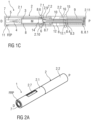
- Figure 1A is a perspective view of an exemplary embodiment of an autoinjector 1 comprising a case 2 and a cap 11 prior to use.
- Figures 1B and 1C are longitudinal sections of the autoinjector 1 prior to use.
- the autoinjector 1 comprises a case 2 including a distal case 2.1 and a proximal case 2.2 which are coupled during assembly.
- a cap 11 is removably coupled to a distal end of the case 2.
- the case 2 comprises a viewing window 2.7, which may be a hole or a transparent portion of the case 2.
- the case 2 is adapted to hold a syringe 3 containing a medicament.
- the syringe 3 may be a pre-filled syringe and have a needle 4 arranged at a distal end.
- the syringe 3 may be a medicament cartridge adapted to removably receive the needle 4 (e.g., by snap-fit, friction, threads, etc.).
- a protective needle sheath 5 may be removably attached to the needle 4.
- a stopper 6 is arranged for sealing the syringe 3 proximally and for displacing a liquid medicament M contained in the syringe 3 through the needle 4.
- a needle shroud 7 is telescoped within the case 2 and movable between an extended position and a retracted position.
- the needle shroud 7 is biased relative to the case 2 toward the extended position by a control spring 9.
- the syringe 3 may be held in a syringe carrier 8, which is slidably arranged within the case 2.
- the syringe carrier 8 may include a distal portion adapted to hold the syringe 3 and a proximal portion adapted to retain a plunger 12.
- a drive spring 10, e.g., a compression spring, may be grounded proximally on a proximal end of the syringe carrier 8 and distally on a distal end of the plunger 12.
- the plunger 12 is telescopically coupled to the proximal portion of the syringe carrier 8, and the drive spring 10 is arranged within the plunger 12 and biases the plunger 12 distally.
- the drive spring 10 is arranged within a proximal part 8.1 of the syringe carrier 8.
- a plunger 12 serves for forwarding the force of the drive spring 10 to the stopper 6.
- the plunger 12 is hollow and telescoped within the proximal part 8.1 of the syringe carrier 8 wherein the drive spring 10 is arranged within the plunger 12 biasing the plunger 12 in the distal direction D against the syringe carrier 8.
- a detent mechanism 14 is provided to initiate automated needle insertion.
- the detent mechanism 14 also locks the needle shroud 7 after autoinjector 1 has been removed from the injection site in an extended position.
- the detent mechanism 14 comprises at least one shroud boss 7.1 adapted to engage in a carrier opening 8.6 within the syringe carrier 8 for locking the needle shroud 7 to the syringe carrier 8. At least one surface of the shroud boss 7.1 and the carrier opening 8.6 may be ramped to reduce a force necessary to displace the needle shroud 7 from the extended position to the retracted position against the biasing force of the control spring 9.
- the shroud boss 7.1 abuts the carrier opening 8.6 and deflects radially via a compliant beam 7.2 coupled to the shroud boss 7.1, disengaging the needle shroud 7 from the syringe carrier 8.
- the shroud boss 7.1 radially abuts a radial case boss 2.9, which prevents the needle shroud 7 from disengaging the syringe carrier 8 when the needle shroud 7 is in the first extended position FEP.
- An axial case boss 2.10 is adapted to distally abut the shroud boss 7.1 such that the needle shroud 7 cannot be moved distally beyond the first extended position FEP prior to use. At least one of the surfaces of the shroud boss 7.1 and the axial case boss 2.10 may be ramped such that if an axial force directed in the distal direction D is applied to the needle shroud 7 relative the case 2, the needle shroud 7 moves in the distal direction D relative the case 2 and the shroud boss 7.1 is radially inwardly deflected via the resilient beam 7.2 around the axial case boss 2.10. Prior to use, the shroud boss 7.1 is prevented from deflecting radially inward by the presence of the syringe carrier 8. Thus, prior to use the needle shroud 7.1 does not disengage the case 2.
- a plunger release mechanism 15 is arranged for preventing release of the plunger 12 prior to the needle 4 reaching an insertion depth and for releasing the plunger 12 once the needle 4 reaches its insertion depth.
- the plunger release mechanism 15 comprises: one or more compliant beams 8.3 with a respective first boss 8.4 arranged on the syringe carrier 8, a respective first opening 12.1 laterally arranged in the plunger 12 for engaging the first boss 8.4, a collar 16 slidably arranged within the case 2 and over the syringe carrier 8. When the needle shroud 7 is in the first extended position FEP, the collar 16 abuts the first boss 8.4, preventing it from disengaging the first opening 12.1.
- the collar 16 moves axially away from the first boss 8.4, so that the first boss 8.4 may deflect via the beam 8.3 and disengage from the first opening 12.1.
- the syringe carrier 8 is then disengaged from the plunger 12.
- At least surface of the first boss 8.4 and the first opening 12.1 may be ramped to reduce a force necessary to disengage the first boss 8.4 from the first opening 12.1.
- a control mechanism 21 (shown in Fig. 3B ) is arranged for selectively coupling the control spring 9 to the syringe carrier 8 or to the needle shroud 7 for advancing either in the distal direction D or opposing movement thereof in the proximal direction P.
- the collar 16 may be a component of the control mechanism 21.
- the control spring 9 is proximally grounded in the case 2 and distally bears against the collar 16 which is movable axially with respect to the case 2 and arranged over the syringe carrier 8.
- the collar 16 comprises at least one collar boss 16.1 adapted to be engaged to a step 8.5 in the carrier 8.
- At least one of the mating surfaces of the carrier boss 16.1 and the step 8.5 may be ramped to reduce a force necessary to deflect the collar boss 16.1 radially via a compliant collar beam 16.2 when it abuts the step 8.5.
- the collar boss 16.1 is prevented from deflecting radially by a narrow section 2.4 in the case 2.
- a wide section 2.5 is arranged distally from the narrow section 2.4.
- control spring 9 prior to use the control spring 9 is compressed between the case 2 and the collar 16.
- the control mechanism 21 couples the collar 16 to the syringe carrier 8 which is in turn coupled to the case 2 by the detent mechanism 14.
- a exemplary embodiment of a sequence of operation of the autoinjector 1 is as follows: Prior to use, the autoinjector 1 is in the state as illustrated in figures 1A to 1C . If applicable, the user removes the autoinjector 1 from a packaging. The medicament M may be viewed through the viewing window 2.7. The cap 11 is removed from the case 2 by pulling the cap 11 in the distal direction D. The cap 11 is coupled to the protective needle sheath 5, and thus removing the cap 11 also removes the protective needle sheath 5. Prior to use, the needle shroud 7 is in the first extended position FEP protruding from the case 2 in the distal direction D. The first extended position FEP is defined by the detent mechanism 14, i.e. by the engagement of the shroud boss 7.1 in the carrier opening 8.6 of the syringe carrier 8 and abutment of the shroud boss 7.1 against the axial case boss 2.10 to prevent it from disengaging the carrier opening 8.6.
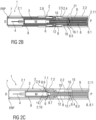
- FIGS 2A-C are perspective views of the autoinjector 1 being pressed against an injection site.
- the needle shroud 7 moves from the first extended position FEP toward a first retracted position FRP relative to the case 2. Because the needle shroud 7 is coupled to the syringe carrier 8 by the detent mechanism 14 (by the shroud boss 7.1 engagement with the carrier opening 8.6), the syringe carrier 8 (and the syringe 3 therein) are retracted relative to the case 2 such that the needle 4 is not exposed. Because the collar 16 is coupled to the syringe carrier 8 (by the collar boss 16.1 abutting the step 8.5), the collar 16 is moved with the syringe carrier 8 in the proximal direction P against the force of the control spring 9.
- the proximal end 8.1 of the syringe carrier 8 may contact (or nearly contact) a proximal end 2.11 of the case 2.
- the contact between the syringe carrier 8 and the case 2 (and/or the increased resistance provided by the control spring 9) may provide a tactile feedback that further depression of the needle shroud 7 will activate the autoinjector 1.
- the shroud boss 7.1 is proximal of the case boss 2.9 such that the shroud boss 7.1 no longer abuts the case boss 2.9.
- the biasing force of the control spring 9 is less than the force required to deflect the shroud boss 7.1 out of the carrier opening 8.6.
- FIGS 3A-C are perspective views of the autoinjector 1 being pressed against an injection site.
- SRP the needle shroud 7 into a second retracted position SRP
- an increase in resistance is experienced as the case 2 advances the syringe carrier 8 in the distal direction D relative to the needle shroud 7 through contact of the proximal ends 2.11, 8.1 of the case 2 and the syringe carrier 8.
- the shroud boss 7.1 is no longer radially supported by the case boss 2.9, as the case 2 is advanced in the distal direction D, the shroud boss 7.1 is deflected radially when it abuts the carrier opening 8.6, causing the syringe carrier 8 to disengage from the needle shroud 7.
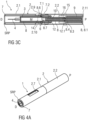
- Figures 4A-C are perspective views of the autoinjector 1 being pressed against an injection site.
- the shroud boss 7.1 disengages the carrier opening 8.6, the syringe carrier 8 is decoupled from the needle shroud 7.
- the control spring 9 applies the biasing force to the collar 16, and the collar boss 16.1 pushes the step 8.5 on the syringe carrier 8 to drive the syringe carrier 8 (and the syringe 3) in the distal direction D.
- the syringe carrier 8 abuts a front stop 2.8 in the case 2, the needle 4 protrudes beyond the distal end of the case 2 and is inserted into the injection site.
- the collar 16 has been advanced in the distal direction D to such an extent, that the collar boss 16.1 is no longer supported by the narrow section 2.4 but has reached the wide section 2.5 of the case 2.
- the control spring 9 continues advancing the collar 16 and due to the syringe carrier 8 having abutted the front stop 2.8, the collar boss 16.1 is deflected radially, disengaging the collar 16 from the syringe carrier 8.
- the collar 16 advances further under the force of the control spring 9 until it abuts the needle shroud 7.
- the collar 16 advances, it is distal of the first boss 8.4 on the syringe carrier 8 so as to allow radially deflection of the first boss 8.4 due to its ramped engagement to the first opening 12.1 under load from the drive spring 10.
- the plunger 12 is thus released and advanced by the drive spring 10 displacing the stopper 6 within the syringe 3 and ejecting the medicament M through the needle 4.
- the release of the plunger release mechanism 15 may provide an audible and/or tactile feedback to the user.
- the progress of the delivery of the medicament M can be observed through the viewing window 2.7 by examining the movement of the plunger 12.
- the plunger 12 (which may be a contrasting color to the case 2) is visible in the viewing window 2.7, providing visual feedback about whether or not the autoinjector 1 has been used.
- the needle shroud 7 moves in the distal direction D, because it is abutted by the collar 16 which is driven by the control spring 9.
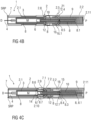
- FIGS 5A-C are perspective views of the autoinjector 1 after it is removed from the injection site.
- the shroud boss 7.1 is deflected radially by the axial case boss 2.10 since the syringe carrier 8 has been moved in the distal direction D during needle insertion and does not abut the shroud boss 7.1.
- the shroud boss 7.1 hence deflects around the case boss 2.10, and then returns to a non-deflected position when it is distal of the case boss 2.10.
- the shroud boss 7.1 abuts a ramped stop 8.7 on the syringe carrier 8 which resolves the remaining axial force of the control spring 9 and arrests the needle shroud's 7 extension.
- the needle shroud 7 is now in a second extended position SEP extending further from the case 2 than in the first extended position FEP and the extended needle 4 is hidden from view and finger access within the needle shroud 7.
- an opening may be arranged in the proximal end 2.11 of the case 2 allowing the proximal part 8.1 of the syringe carrier 8 to protrude proximally from the case 2 and serve as a trigger button (not shown).
- the detent mechanism 14 prevents release of the trigger button prior to depression of the needle shroud 7 into the retracted position RP.
- the needle shroud 7 may be fully depressed into the second retracted position SRP thereby extending the proximal part 8.1 of the syringe carrier 8 from the case 2 which may then be depressed to start an injection.
- the needle shroud 7 can re-extend into the first extended position FEP and the autoinjector 1 can return to its initial state. If the trigger button is depressed, it may be locked to the case in the depressed position to provide a visual indication that the autoinjector 1 has been used.
- the shroud boss 7.1 is no longer supported by the case boss 2.9.
- the trigger button e.g., the proximal end 8.1 of the syringe carrier 8 protruding proximally from the case 2 can now be depressed thereby radially outwardly deflecting the shroud boss 7.1 out of engagement with the carrier opening 8.6 due to their ramped engagement.
- the syringe carrier 8 is thus decoupled from the needle shroud 7 and the control spring 9, coupled to the syringe carrier 8 through the control mechanism 21, advances the syringe carrier 8 in the distal direction D extending the needle 4 from the case 2 in the distal direction D.
- the length of the syringe carrier 8 and the case 2 may be such that the proximal end 8.1 of the syringe carrier 8 is flush with the proximal end 2.11 of the case 2 once the needle 4 reaches its insertion depth.
- drug or “medicament”, as used herein, means a pharmaceutical formulation containing at least one pharmaceutically active compound
- Insulin analogues are for example Gly(A21), Arg(B31), Arg(B32) human insulin; Lys(B3), Glu(B29) human insulin; Lys(B28), Pro(B29) human insulin; Asp(B28) human insulin; human insulin, wherein proline in position B28 is replaced by Asp, Lys, Leu, Val or Ala and wherein in position B29 Lys may be replaced by Pro; Ala(B26) human insulin; Des(B28-B30) human insulin; Des(B27) human insulin and Des(B30) human insulin.
- Insulin derivates are for example B29-N-myristoyl-des(B30) human insulin; B29-N-palmitoyl-des(B30) human insulin; B29-N-myristoyl human insulin; B29-N-palmitoyl human insulin; B28-N-myristoyl LysB28ProB29 human insulin; B28-N-palmitoyl-LysB28ProB29 human insulin; B30-N-myristoyl-ThrB29LysB30 human insulin; B30-N-palmitoyl- ThrB29LysB30 human insulin; B29-N-(N-palmitoyl-Y-glutamyl)-des(B30) human insulin; B29-N-(N-lithocholyl-Y-glutamyl)-des(B30) human insulin; B29-N-( ⁇ -carboxyheptadecanoyl)-des(B30) human insulin and B29-N-( ⁇ -carbox
- Exendin-4 for example means Exendin-4(1-39), a peptide of the sequence H-His-Gly-Glu-Gly-Thr-Phe-Thr-Ser-Asp-Leu-Ser-Lys-Gln-Met-Glu-Glu-Glu-Ala-Val-Arg-Leu-Phe-Ile-Glu-Trp-Leu-Lys-Asn-Gly-Gly-Pro-Ser-Ser-Gly-Ala-Pro-Pro-Pro-Ser-NH2.
- Exendin-4 derivatives are for example selected from the following list of compounds:
- Hormones are for example hypophysis hormones or hypothalamus hormones or regulatory active peptides and their antagonists as listed in Rote Liste, ed. 2008, Chapter 50 , such as Gonadotropine (Follitropin, Lutropin, Choriongonadotropin, Menotropin), Somatropine (Somatropin), Desmopressin, Terlipressin, Gonadorelin, Triptorelin, Leuprorelin, Buserelin, Nafarelin, Goserelin.
- Gonadotropine Follitropin, Lutropin, Choriongonadotropin, Menotropin
- Somatropine Somatropin
- Desmopressin Terlipressin
- Gonadorelin Triptorelin
- Leuprorelin Buserelin
- Nafarelin Goserelin.
- a polysaccharide is for example a glucosaminoglycane, a hyaluronic acid, a heparin, a low molecular weight heparin or an ultra low molecular weight heparin or a derivative thereof, or a sulphated, e.g. a poly-sulphated form of the above-mentioned polysaccharides, and/or a pharmaceutically acceptable salt thereof.
- An example of a pharmaceutically acceptable salt of a poly-sulphated low molecular weight heparin is enoxaparin sodium.
- Antibodies are globular plasma proteins (-150 kDa) that are also known as immunoglobulins which share a basic structure. As they have sugar chains added to amino acid residues, they are glycoproteins.
- the basic functional unit of each antibody is an immunoglobulin (Ig) monomer (containing only one Ig unit); secreted antibodies can also be dimeric with two Ig units as with IgA, tetrameric with four Ig units like teleost fish IgM, or pentameric with five Ig units, like mammalian IgM.
- Ig immunoglobulin
- the Ig monomer is a "Y"-shaped molecule that consists of four polypeptide chains; two identical heavy chains and two identical light chains connected by disulfide bonds between cysteine residues. Each heavy chain is about 440 amino acids long; each light chain is about 220 amino acids long. Heavy and light chains each contain intrachain disulfide bonds which stabilize their folding. Each chain is composed of structural domains called Ig domains. These domains contain about 70-110 amino acids and are classified into different categories (for example, variable or V, and constant or C) according to their size and function. They have a characteristic immunoglobulin fold in which two ⁇ sheets create a "sandwich" shape, held together by interactions between conserved cysteines and other charged amino acids.
- Ig heavy chain There are five types of mammalian Ig heavy chain denoted by ⁇ , ⁇ , ⁇ , ⁇ , and ⁇ .
- the type of heavy chain present defines the isotype of antibody; these chains are found in IgA, IgD, IgE, IgG, and IgM antibodies, respectively.
- Distinct heavy chains differ in size and composition; ⁇ and ⁇ contain approximately 450 amino acids and ⁇ approximately 500 amino acids, while ⁇ and ⁇ have approximately 550 amino acids.
- Each heavy chain has two regions, the constant region (C H ) and the variable region (V H ).
- the constant region is essentially identical in all antibodies of the same isotype, but differs in antibodies of different isotypes.
- Heavy chains ⁇ , ⁇ and ⁇ have a constant region composed of three tandem Ig domains, and a hinge region for added flexibility; heavy chains ⁇ and ⁇ have a constant region composed of four immunoglobulin domains.
- the variable region of the heavy chain differs in antibodies produced by different B cells, but is the same for all antibodies produced by a single B cell or B cell clone.
- the variable region of each heavy chain is approximately 110 amino acids long and is composed of a single Ig domain.
- a light chain has two successive domains: one constant domain (CL) and one variable domain (VL).
- CL constant domain
- VL variable domain
- the approximate length of a light chain is 211 to 217 amino acids.
- Each antibody contains two light chains that are always identical; only one type of light chain, ⁇ or ⁇ , is present per antibody in mammals.
- variable (V) regions are responsible for binding to the antigen, i.e. for its antigen specificity.
- VL variable light
- VH variable heavy chain
- CDRs Complementarity Determining Regions
- an "antibody fragment” contains at least one antigen binding fragment as defined above, and exhibits essentially the same function and specificity as the complete antibody of which the fragment is derived from.
- Limited proteolytic digestion with papain cleaves the Ig prototype into three fragments. Two identical amino terminal fragments, each containing one entire L chain and about half an H chain, are the antigen binding fragments (Fab).
- the Fc contains carbohydrates, complement-binding, and FcR-binding sites.
- F(ab')2 is divalent for antigen binding.
- the disulfide bond of F(ab')2 may be cleaved in order to obtain Fab'.
- the variable regions of the heavy and light chains can be fused together to form a single chain variable fragment (scFv).
- Pharmaceutically acceptable salts are for example acid addition salts and basic salts.
- Acid addition salts are e.g. HCl or HBr salts.
- Basic salts are e.g. salts having a cation selected from alkali or alkaline, e.g. Na+, or K+, or Ca2+, or an ammonium ion N+(R1)(R2)(R3)(R4), wherein R1 to R4 independently of each other mean: hydrogen, an optionally substituted C1-C6-alkyl group, an optionally substituted C2-C6-alkenyl group, an optionally substituted C6-C10-aryl group, or an optionally substituted C6-C10-heteroaryl group.
- solvates are for example hydrates.
- EP 22156678.9 is a divisional application of EP 18189942.8 , the disclosure of which is herewith explicitly incorporated by reference into the present disclosure for all purposes.
- EP 18189942.8 is a divisional application of EP 14736783.3 , the disclosure of which is herewith explicitly incorporated by reference into the present disclosure for all purposes.
Landscapes
- Health & Medical Sciences (AREA)
- Engineering & Computer Science (AREA)
- Heart & Thoracic Surgery (AREA)
- Vascular Medicine (AREA)
- Anesthesiology (AREA)
- Biomedical Technology (AREA)
- Hematology (AREA)
- Life Sciences & Earth Sciences (AREA)
- Animal Behavior & Ethology (AREA)
- General Health & Medical Sciences (AREA)
- Public Health (AREA)
- Veterinary Medicine (AREA)
- Environmental & Geological Engineering (AREA)
- Infusion, Injection, And Reservoir Apparatuses (AREA)
Applications Claiming Priority (5)
| Application Number | Priority Date | Filing Date | Title |
|---|---|---|---|
| EP13175660.3A EP2823837A1 (de) | 2013-07-09 | 2013-07-09 | Autoinjektor |
| EP18189942.8A EP3434302B1 (de) | 2013-07-09 | 2014-07-07 | Autoinjektor |
| EP14736783.3A EP3019217B1 (de) | 2013-07-09 | 2014-07-07 | Autoinjektor |
| EP22156678.9A EP4056212B1 (de) | 2013-07-09 | 2014-07-07 | Autoinjektor |
| PCT/EP2014/064423 WO2015004048A1 (en) | 2013-07-09 | 2014-07-07 | Autoinjector |
Related Parent Applications (4)
| Application Number | Title | Priority Date | Filing Date |
|---|---|---|---|
| EP14736783.3A Division EP3019217B1 (de) | 2013-07-09 | 2014-07-07 | Autoinjektor |
| EP18189942.8A Division EP3434302B1 (de) | 2013-07-09 | 2014-07-07 | Autoinjektor |
| EP22156678.9A Division-Into EP4056212B1 (de) | 2013-07-09 | 2014-07-07 | Autoinjektor |
| EP22156678.9A Division EP4056212B1 (de) | 2013-07-09 | 2014-07-07 | Autoinjektor |
Publications (2)
| Publication Number | Publication Date |
|---|---|
| EP4445933A2 true EP4445933A2 (de) | 2024-10-16 |
| EP4445933A3 EP4445933A3 (de) | 2025-01-01 |
Family
ID=48747442
Family Applications (5)
| Application Number | Title | Priority Date | Filing Date |
|---|---|---|---|
| EP13175660.3A Withdrawn EP2823837A1 (de) | 2013-07-09 | 2013-07-09 | Autoinjektor |
| EP14736783.3A Active EP3019217B1 (de) | 2013-07-09 | 2014-07-07 | Autoinjektor |
| EP18189942.8A Active EP3434302B1 (de) | 2013-07-09 | 2014-07-07 | Autoinjektor |
| EP22156678.9A Active EP4056212B1 (de) | 2013-07-09 | 2014-07-07 | Autoinjektor |
| EP24197383.3A Pending EP4445933A3 (de) | 2013-07-09 | 2014-07-07 | Autoinjektor |
Family Applications Before (4)
| Application Number | Title | Priority Date | Filing Date |
|---|---|---|---|
| EP13175660.3A Withdrawn EP2823837A1 (de) | 2013-07-09 | 2013-07-09 | Autoinjektor |
| EP14736783.3A Active EP3019217B1 (de) | 2013-07-09 | 2014-07-07 | Autoinjektor |
| EP18189942.8A Active EP3434302B1 (de) | 2013-07-09 | 2014-07-07 | Autoinjektor |
| EP22156678.9A Active EP4056212B1 (de) | 2013-07-09 | 2014-07-07 | Autoinjektor |
Country Status (7)
| Country | Link |
|---|---|
| US (3) | US10583260B2 (de) |
| EP (5) | EP2823837A1 (de) |
| JP (1) | JP6475237B2 (de) |
| CN (1) | CN105579083B (de) |
| DK (3) | DK3019217T3 (de) |
| TW (1) | TW201521813A (de) |
| WO (1) | WO2015004048A1 (de) |
Families Citing this family (59)
| Publication number | Priority date | Publication date | Assignee | Title |
|---|---|---|---|---|
| US20090093793A1 (en) | 2007-10-02 | 2009-04-09 | Yossi Gross | External drug pump |
| JP6208136B2 (ja) | 2011-09-22 | 2017-10-04 | アッヴィ・インコーポレイテッド | 自動注入装置 |
| CA2849810A1 (en) | 2011-09-22 | 2013-03-28 | Abbvie Inc. | Automatic injection device |
| EP2823837A1 (de) | 2013-07-09 | 2015-01-14 | Sanofi-Aventis Deutschland GmbH | Autoinjektor |
| GB2538486A (en) * | 2015-04-30 | 2016-11-23 | Owen Mumford Ltd | Injection Device |
| TW201711716A (zh) | 2015-06-03 | 2017-04-01 | 賽諾菲阿凡提斯德意志有限公司 | 護罩鎖 |
| US10576207B2 (en) | 2015-10-09 | 2020-03-03 | West Pharma. Services IL, Ltd. | Angled syringe patch injector |
| JP7044708B2 (ja) | 2015-10-09 | 2022-03-30 | ウェスト ファーマ サービシーズ イスラエル リミテッド | カスタマイズシリンジの充填方法 |
| FR3043563B1 (fr) * | 2015-11-13 | 2022-01-21 | Aptar France Sas | Autoinjecteur. |
| USD822198S1 (en) * | 2015-12-09 | 2018-07-03 | Amgen Inc. | Autoinjector with removable autoinjector cap |
| CN113041432B (zh) | 2016-01-21 | 2023-04-07 | 西医药服务以色列有限公司 | 包括视觉指示物的药剂输送装置 |
| CN109310816B (zh) | 2016-01-21 | 2020-04-21 | 西医药服务以色列有限公司 | 针插入和缩回机构 |
| JP6513297B2 (ja) | 2016-01-21 | 2019-05-22 | ウェスト ファーマ サービシーズ イスラエル リミテッド | 自動注射器、受け入れフレーム及び自動注射器におけるカートリッジの接続方法 |
| US20170246395A1 (en) * | 2016-02-29 | 2017-08-31 | Shl Group Ab | Delivery Device |
| US11065390B2 (en) | 2016-02-29 | 2021-07-20 | Shl Medical Ag | Automatic delivery device with end of injection indication device |
| USD866757S1 (en) * | 2016-03-11 | 2019-11-12 | Millennium Pharmaceuticals, Inc. | Autoinjector |
| WO2017161076A1 (en) * | 2016-03-16 | 2017-09-21 | Medimop Medical Projects Ltd. | Staged telescopic screw assembly having different visual indicators |
| USD818587S1 (en) | 2016-03-29 | 2018-05-22 | Abbevie Inc. | Automatic injection device |
| USD819198S1 (en) | 2016-04-28 | 2018-05-29 | Amgen Inc. | Autoinjector with removable cap |
| US10426897B2 (en) | 2016-04-28 | 2019-10-01 | Carebay Europe Ltd | Container holder assembly for a medicament delivery device and medicament delivery device comprising the container holder assembly |
| USD830539S1 (en) * | 2016-05-02 | 2018-10-09 | Amgen Inc. | Autoinjector |
| KR101805681B1 (ko) | 2016-06-08 | 2017-12-06 | 재단법인대구경북과학기술원 | 주사 가젯 |
| US10792432B2 (en) * | 2016-06-09 | 2020-10-06 | Becton, Dickinson And Company | Drive assembly and spacer for drug delivery system |
| US10549044B2 (en) | 2016-06-09 | 2020-02-04 | Becton, Dickinson And Company | Spacer assembly for drug delivery system |
| EP3490635B1 (de) | 2016-08-01 | 2021-11-17 | West Pharma. Services Il, Ltd. | Feder zur verhinderung eines unvollständigen verschliessen der tür |
| EP3490643B1 (de) | 2016-08-01 | 2021-10-27 | West Pharma. Services Il, Ltd. | Verdrehsicherungsstift |
| EP3503949A1 (de) | 2016-08-26 | 2019-07-03 | Sanofi-Aventis Deutschland GmbH | Hörbarer indikator |
| GB2557655A (en) | 2016-12-14 | 2018-06-27 | Teva Pharma | Medical injection device packaging |
| EP3595750B1 (de) | 2017-03-15 | 2021-08-11 | Owen Mumford Limited | Injektionsvorrichtung |
| USD819804S1 (en) * | 2017-04-28 | 2018-06-05 | Ucb Biopharma Sprl | Injector |
| JP6921997B2 (ja) | 2017-05-30 | 2021-08-18 | ウェスト ファーマ サービシーズ イスラエル リミテッド | ウェアラブル注射器のモジュラ駆動トレイン |
| EP4397336A3 (de) | 2017-10-16 | 2024-10-09 | Becton, Dickinson and Company | Abstandshalteranordnung für eine arzneimittelabgabevorrichtung |
| JP1629608S (de) * | 2017-10-25 | 2019-04-15 | ||
| USD926967S1 (en) * | 2018-05-22 | 2021-08-03 | Sanofi | Injection device |
| USD866752S1 (en) * | 2018-05-22 | 2019-11-12 | Sanofi | Injection device |
| KR102798352B1 (ko) | 2018-05-24 | 2025-04-23 | 노파르티스 아게 | 자동 약물 전달 디바이스 |
| GB2577549B (en) * | 2018-09-28 | 2021-08-04 | Owen Mumford Ltd | Injection device with commit feature |
| EP3930790A1 (de) | 2019-02-26 | 2022-01-05 | Becton Dickinson France | Autoinjektor mit audioindikator |
| WO2020260576A1 (en) * | 2019-06-28 | 2020-12-30 | Novo Nordisk A/S | Drug delivery device with plunger rod having nonuniform stopper interface |
| USD1010811S1 (en) | 2019-09-30 | 2024-01-09 | Amgen Inc. | Handheld drug delivery device |
| USD1030041S1 (en) | 2020-01-14 | 2024-06-04 | Amgen Inc. | Handheld drug delivery device |
| USD1030040S1 (en) | 2020-01-14 | 2024-06-04 | Amgen Inc. | Handheld drug delivery device |
| USD956211S1 (en) | 2020-02-28 | 2022-06-28 | Amgen Inc. | Handheld drug delivery device |
| USD973866S1 (en) | 2020-11-05 | 2022-12-27 | Amgen Inc. | Handheld drug delivery device |
| USD974547S1 (en) | 2020-11-05 | 2023-01-03 | Amgen Inc. | Handheld drug delivery device |
| JP2021500643S (ja) | 2020-11-05 | 2022-12-27 | 注射器 | |
| USD985117S1 (en) | 2021-03-10 | 2023-05-02 | Amgen Inc. | Handheld drug delivery device |
| USD985116S1 (en) | 2021-03-10 | 2023-05-02 | Amgen Inc. | Handheld drug delivery device |
| USD985118S1 (en) | 2021-03-10 | 2023-05-02 | Amgen Inc. | Handheld drug delivery device |
| USD985119S1 (en) | 2021-03-30 | 2023-05-02 | Amgen Inc. | Handheld drug delivery device |
| CN119816338A (zh) * | 2022-09-05 | 2025-04-11 | 贝克顿迪金森法国公司 | 用于将产品自动注射到注射部位中的自动注射装置 |
| JP2025537575A (ja) * | 2022-11-15 | 2025-11-18 | ベクトン ディキンソン フランス | 自動注入器 |
| USD1049366S1 (en) * | 2023-08-08 | 2024-10-29 | Amgen Inc. | Handheld drug delivery device |
| USD1051366S1 (en) | 2023-08-08 | 2024-11-12 | Amgen Inc. | Handheld drug delivery device |
| USD1049367S1 (en) | 2023-08-08 | 2024-10-29 | Amgen Inc. | Handheld drug delivery device |
| USD1049369S1 (en) | 2023-09-25 | 2024-10-29 | Amgen Inc. | Handheld drug delivery device |
| USD1051367S1 (en) * | 2023-09-25 | 2024-11-12 | Amgen Inc. | Handheld drug delivery device |
| USD1050422S1 (en) | 2023-09-25 | 2024-11-05 | Amgen Inc. | Handheld drug delivery device |
| WO2025199106A1 (en) * | 2024-03-19 | 2025-09-25 | Halozyme, Inc. | Autoinjector |
Family Cites Families (19)
| Publication number | Priority date | Publication date | Assignee | Title |
|---|---|---|---|---|
| US20050101919A1 (en) * | 2003-11-07 | 2005-05-12 | Lennart Brunnberg | Device for an injector |
| GB2433032A (en) * | 2005-12-08 | 2007-06-13 | Owen Mumford Ltd | Syringe with dose adjustment means |
| WO2009007229A1 (en) | 2007-07-06 | 2009-01-15 | Shl Medical Ab | One shot injector with dual springs |
| CN101983079B (zh) * | 2007-11-14 | 2014-07-02 | Shl集团有限责任公司 | 能主动触发针筒撤回的自动注射装置 |
| DK3017837T3 (en) * | 2008-10-29 | 2017-04-10 | Shl Group Ab | INJECTION DEVICE |
| AU2010303987B2 (en) * | 2009-10-08 | 2012-10-18 | Shl Medical Ag | Medicament delivery device |
| KR101419160B1 (ko) | 2010-03-01 | 2014-07-11 | 일라이 릴리 앤드 캄파니 | 이중 기능 편위 부재를 포함하는 지연 기구를 구비한 자동 주입 장치 |
| IT1398501B1 (it) | 2010-03-10 | 2013-03-01 | Menarini Int Operations Lu Sa | Dispositivo autoiniettore di due dosi di farmaco |
| EP2438942A1 (de) * | 2010-10-08 | 2012-04-11 | Sanofi-Aventis Deutschland GmbH | Automatischer Injektor |
| EP2438939A1 (de) * | 2010-10-08 | 2012-04-11 | Sanofi-Aventis Deutschland GmbH | Anordnung zum Ankoppeln eines Kolbens an eine Spritze oder einen Stopfer |
| EP2438943A1 (de) * | 2010-10-08 | 2012-04-11 | Sanofi-Aventis Deutschland GmbH | Automatischer Injektor |
| WO2012045833A1 (en) | 2010-10-08 | 2012-04-12 | Sanofi-Aventis Deutschland Gmbh | Auto-injector |
| GB2486693B (en) * | 2010-12-22 | 2016-05-18 | Owen Mumford Ltd | Autoinjectors and manufacturing systems thereof |
| EP2489387A1 (de) * | 2011-02-18 | 2012-08-22 | Sanofi-Aventis Deutschland GmbH | Automatischer Injektor |
| EP2489380A1 (de) * | 2011-02-18 | 2012-08-22 | Sanofi-Aventis Deutschland GmbH | Injektionsvorrichtung |
| PL2750738T3 (pl) | 2011-08-31 | 2024-07-15 | Shl Medical Ag | Urządzenie do wstrzykiwania |
| US9775948B2 (en) * | 2011-09-09 | 2017-10-03 | Merck Patent Gmbh | Auto injector with separate needle injection |
| AU2014260230B2 (en) * | 2013-05-01 | 2019-02-14 | Unl Holdings Llc | Plunger-driven auto-injectors |
| EP2823837A1 (de) | 2013-07-09 | 2015-01-14 | Sanofi-Aventis Deutschland GmbH | Autoinjektor |
-
2013
- 2013-07-09 EP EP13175660.3A patent/EP2823837A1/de not_active Withdrawn
-
2014
- 2014-07-07 US US14/903,390 patent/US10583260B2/en active Active
- 2014-07-07 EP EP14736783.3A patent/EP3019217B1/de active Active
- 2014-07-07 DK DK14736783.3T patent/DK3019217T3/en active
- 2014-07-07 CN CN201480048472.2A patent/CN105579083B/zh active Active
- 2014-07-07 JP JP2016524772A patent/JP6475237B2/ja active Active
- 2014-07-07 EP EP18189942.8A patent/EP3434302B1/de active Active
- 2014-07-07 DK DK22156678.9T patent/DK4056212T3/da active
- 2014-07-07 EP EP22156678.9A patent/EP4056212B1/de active Active
- 2014-07-07 EP EP24197383.3A patent/EP4445933A3/de active Pending
- 2014-07-07 TW TW103123249A patent/TW201521813A/zh unknown
- 2014-07-07 DK DK18189942.8T patent/DK3434302T3/da active
- 2014-07-07 WO PCT/EP2014/064423 patent/WO2015004048A1/en not_active Ceased
-
2020
- 2020-01-30 US US16/777,509 patent/US11951292B2/en active Active
-
2024
- 2024-03-19 US US18/609,407 patent/US20240216618A1/en active Pending
Non-Patent Citations (1)
| Title |
|---|
| "Remington's Pharmaceutical Sciences", 1985, MARK PUBLISHING COMPANY |
Also Published As
| Publication number | Publication date |
|---|---|
| CN105579083B (zh) | 2019-10-25 |
| US11951292B2 (en) | 2024-04-09 |
| DK3019217T3 (en) | 2019-01-21 |
| DK3434302T3 (da) | 2022-05-23 |
| WO2015004048A1 (en) | 2015-01-15 |
| EP3434302A1 (de) | 2019-01-30 |
| EP4056212B1 (de) | 2024-10-09 |
| US10583260B2 (en) | 2020-03-10 |
| HK1218522A1 (en) | 2017-02-24 |
| EP3019217B1 (de) | 2018-09-19 |
| EP3434302B1 (de) | 2022-03-09 |
| TW201521813A (zh) | 2015-06-16 |
| EP4445933A3 (de) | 2025-01-01 |
| JP6475237B2 (ja) | 2019-02-27 |
| CN105579083A (zh) | 2016-05-11 |
| DK4056212T3 (da) | 2025-01-02 |
| US20240216618A1 (en) | 2024-07-04 |
| EP4056212A1 (de) | 2022-09-14 |
| EP3019217A1 (de) | 2016-05-18 |
| US20160151586A1 (en) | 2016-06-02 |
| EP2823837A1 (de) | 2015-01-14 |
| JP2016536060A (ja) | 2016-11-24 |
| US20200164156A1 (en) | 2020-05-28 |
Similar Documents
| Publication | Publication Date | Title |
|---|---|---|
| US20240216618A1 (en) | Autoinjector | |
| US20220143322A1 (en) | Autoinjector | |
| US12070589B2 (en) | Autoinjector | |
| EP2823839A1 (de) | Autoinjektor | |
| EP2823836A1 (de) | Autoinjektor | |
| HK40081254A (en) | Autoinjector | |
| HK40079870A (en) | Autoinjector | |
| HK1218522B (en) | Autoinjector | |
| HK1218400B (en) | Autoinjector | |
| HK1218521B (en) | Autoinjector |
Legal Events
| Date | Code | Title | Description |
|---|---|---|---|
| PUAI | Public reference made under article 153(3) epc to a published international application that has entered the european phase |
Free format text: ORIGINAL CODE: 0009012 |
|
| STAA | Information on the status of an ep patent application or granted ep patent |
Free format text: STATUS: THE APPLICATION HAS BEEN PUBLISHED |
|
| AC | Divisional application: reference to earlier application |
Ref document number: 3019217 Country of ref document: EP Kind code of ref document: P Ref document number: 3434302 Country of ref document: EP Kind code of ref document: P Ref document number: 4056212 Country of ref document: EP Kind code of ref document: P |
|
| AK | Designated contracting states |
Kind code of ref document: A2 Designated state(s): AL AT BE BG CH CY CZ DE DK EE ES FI FR GB GR HR HU IE IS IT LI LT LU LV MC MK MT NL NO PL PT RO RS SE SI SK SM TR |
|
| REG | Reference to a national code |
Ref country code: DE Ref legal event code: R079 Free format text: PREVIOUS MAIN CLASS: A61M0005500000 Ipc: A61M0005200000 |
|
| PUAL | Search report despatched |
Free format text: ORIGINAL CODE: 0009013 |
|
| AK | Designated contracting states |
Kind code of ref document: A3 Designated state(s): AL AT BE BG CH CY CZ DE DK EE ES FI FR GB GR HR HU IE IS IT LI LT LU LV MC MK MT NL NO PL PT RO RS SE SI SK SM TR |
|
| RIC1 | Information provided on ipc code assigned before grant |
Ipc: A61M 5/32 20060101ALN20241126BHEP Ipc: A61M 5/20 20060101AFI20241126BHEP |
|
| STAA | Information on the status of an ep patent application or granted ep patent |
Free format text: STATUS: REQUEST FOR EXAMINATION WAS MADE |
|
| 17P | Request for examination filed |
Effective date: 20250620 |