EP4440974B1 - Aufzugsschutzsystem - Google Patents
Aufzugsschutzsystem Download PDFInfo
- Publication number
- EP4440974B1 EP4440974B1 EP21844197.0A EP21844197A EP4440974B1 EP 4440974 B1 EP4440974 B1 EP 4440974B1 EP 21844197 A EP21844197 A EP 21844197A EP 4440974 B1 EP4440974 B1 EP 4440974B1
- Authority
- EP
- European Patent Office
- Prior art keywords
- protective structure
- elevator
- protective
- elevator cabin
- edge
- Prior art date
- Legal status (The legal status is an assumption and is not a legal conclusion. Google has not performed a legal analysis and makes no representation as to the accuracy of the status listed.)
- Active
Links
Images

Classifications
-
- B—PERFORMING OPERATIONS; TRANSPORTING
- B66—HOISTING; LIFTING; HAULING
- B66B—ELEVATORS; ESCALATORS OR MOVING WALKWAYS
- B66B11/00—Main component parts of lifts in, or associated with, buildings or other structures
- B66B11/02—Cages, i.e. cars
- B66B11/0226—Constructional features, e.g. walls assembly, decorative panels, comfort equipment, thermal or sound insulation
-
- B—PERFORMING OPERATIONS; TRANSPORTING
- B66—HOISTING; LIFTING; HAULING
- B66B—ELEVATORS; ESCALATORS OR MOVING WALKWAYS
- B66B17/00—Hoistway equipment
- B66B17/12—Counterpoises
-
- B—PERFORMING OPERATIONS; TRANSPORTING
- B66—HOISTING; LIFTING; HAULING
- B66B—ELEVATORS; ESCALATORS OR MOVING WALKWAYS
- B66B7/00—Other common features of elevators
- B66B7/06—Arrangements of ropes or cables
Definitions
- the present invention relates to a movable element of an elevator like an elevator cabin or a counterweight, an elevator, a system for protecting an elevator and a method for retrofitting an elevator.
- An elevator comprises at least one movable element, an elevator lifting mechanism and an elevator pathway.
- the at least one movable element comprises the elevator cabin for transporting persons and/or goods.
- the at least one movable element comprises preferably also a counter-weight.
- the elevator can be a person elevator for transporting humans. Such person elevators include control elements within the elevator cabin allowing the transported persons to select the floor they want to go.
- the elevator can also be a goods elevator for transporting (only non-human) objects. Such goods elevators do not have control elements within the elevator cabin allowing to select the floor from within the elevator cabin.
- the elevator pathway is the pathway for the movable elements of the elevator.
- the pathway extends in the movement direction, preferably a vertical direction such that the movable element(s) can move in a vertical direction back and forth, preferably up and down.
- the pathway comprises preferably a plurality of entrance doors at different levels/floors of the pathway or the house in which the elevator is installed.
- the pathway is at least partly open. The open portions of the pathway allow an object to enter the pathway of the movable object so that this object could collide with the moving movable element.
- the object colliding with the movable element can be a non-human object or a (part of a) human body.
- the open portions are partly open meaning that a person cannot enter fully into the pathway but could enter with an arm or a rod into the pathway.
- Partly open portions are for example open portions which are closed by a grid or a grid door. Such a grid door is often installed at the entrances into the pathway at the different floors.
- the pathway is defined as the projection of the movable element into the movement direction of the movable element from the lowest point of the movable element in the pathway to the highest point of the movable element in the pathway.
- the pathway is defined as the three-dimensional space covered by the movable element in any elevation state of the elevator.
- Each movable element has a distinct pathway.
- the elevator cabin can have a first pathway and the counterweight can have a second pathway.
- the highest point of the first pathway can be or lower than the highest point of the second pathway.
- the pathway of the elevator is provided by the combination of the pathways of each movable element.
- the term pathway refers always to the movable element in question.
- the pathway comprises preferably guide means 2 to guide the movable elements into the designated pathway.
- the first pathway comprises guide means 2, preferably two rails 2, to guide the elevator cabin into the designated first pathway.
- elevators without guide means.
- the elevator lifting mechanism is a mechanism for moving the elevator cabin in the pathway back and forth or up and down.
- the elevator lifting mechanism is preferably a cable drive.
- the cable drive comprises a motor and a cable.
- the cable suspends the elevator cabin on one end.
- the cable extends (in the first pathway) from the elevator cabin to the top of the elevator pathway and is guided back down (in the second pathway) to the counterweight.
- the motor is configured to move the cable such that the elevator cabin moves up and down.
- other elevator lifting mechanism like hydraulic lifting mechanism could be used. In this case, the elevator cabin could be supported by a hydraulic piston moving the elevator cabin back and forth. Also, other lifting elevator mechanisms can be used.
- the elevator cabin comprises a top side, a bottom side and at least one lateral side. If the elevator cabin has a rectangular cross-section (perpendicular to the movement direction), the lateral side comprises preferably a first lateral side, a second lateral side, a third lateral side and a fourth lateral side. The first lateral side is opposed to the third lateral side. The second lateral side is opposed to the fourth lateral side.
- the elevator cabin comprises a top edge between the lateral side and the top side. The top edge refers to the peripheral edge of the elevator cabin on the top side.
- the first portion comprises the portion of the elevator cabin between the cabin frame 5 and the first lateral side, preferably also between the (first portion) second lateral side, the (first portion) fourth lateral side, the (first portion) top side and/or the (first portion) bottom side.
- the second portion comprises the portion of the elevator cabin between the cabin frame 5 and the third lateral side, preferably also between the (second portion) second lateral side, the (second portion) fourth lateral side, the (second portion) top side and/or the (second portion) bottom side.
- the first portion top edge refers to the edge between the first portion top side and the first portion lateral side.
- the second portion top edge refers to the edge between the second portion top side and the second portion lateral side.
- the first portion bottom edge refers to the edge between the first portion bottom side and the first portion lateral side.
- the second portion bottom edge refers to the edge between the second portion bottom side and the second portion lateral side.
- the elevator cabin preferably the cabin frame 5 has generally guide means for the guide means 2 of the pathway.
- the guide means of the elevator cabin is arranged the second and/or fourth lateral side of the elevator cabin or cabin frame 5.
- the elevator cabin and/or the cabin box 1 comprises preferably an entrance into the cabin box 1.
- the entrance of the elevator cabin is arranged for example on the first lateral side.
- the entrance of the elevator cabin is arranged such that it corresponds to the entrance into the elevator/pathway in each floor, when the elevator cabin stops at the respective floor.
- the entrance of the elevator cabin is preferably closable by a closing means like a door.
- the closing means is a grill gate 4.
- the entrance comprises on the inner side of the closing means an inner electronic detector for detecting, if an object approaches from the inside of the cabin box 1 towards the closing means, e.g. the grill gate 4.
- the inner electronic detector can be a light curtain being arranged parallel to the closing means.
- the elevator cabin and/or cabin box 1 might have more than one entrance, e.g. at different lateral sides.
- the elevator cabin has preferably a toe guard 3 on the bottom of the entrance of the elevator cabin.
- the toe guard 3 is preferably arranged on the (first) bottom edge of the elevator cabin in the prolongation of the elevator cabin.
- the invention refers to a system for protecting elevator cabin (or other movable elements) of the elevator.
- the system can be easily retrofitted to existing elevators as described above but can also be implemented in new elevators.
- the system comprises a protective structure 6, a shock-absorbing system 7 and a collision detector.
- the protective structure is connected to the elevator cabin via the shock-absorbing system 7 holding the protective structure 6 in an operating position and allowing the protective structure 6 to move against the driving direction of the of the elevator cabin, when the protective structure 6 hits an object during driving of the elevator.
- the protective structure 6 has a top protective element which in the operating position is arranged above the top edge and is extending along the top edge. This means that the top protective element is arranged such that a projection in the driving direction of the peripheral edge/side of the top protective element would correspond to the top edge of the of the elevator cabin. Thus, when the elevator cabin moves upwards and an object is in the pathway of the elevator cabin, the top protective element would hit the object before the object is hit by the top edge of the elevator cabin.
- the peripheral edge of the top protective element must (in the direction perpendicular to the driving direction and to the top edge direction) correspond at least to the (peripheral) top edge of the elevator cabin, preferably must (in the direction perpendicular to the driving direction and to the top edge direction) extend beyond the (peripheral) top edge.
- the protective structure 6 has a bottom protective element which in the operating position is arranged below the bottom edge and is extending along the bottom edge. This means that the bottom protective element is arranged such that a projection in the driving direction of the peripheral edge/side of the bottom protective element would correspond to the bottom edge of the of the elevator cabin. Thus, when the elevator cabin moves downwards and an object is in the pathway of the elevator cabin, the bottom protective element would hit the object before the object is hit by the bottom edge of the elevator cabin.
- the peripheral edge of the bottom protective element must (in the direction perpendicular to the driving direction and to the bottom edge direction) correspond at least to the (peripheral) bottom edge of the elevator cabin, preferably must (in the direction perpendicular to the driving direction and to the bottom edge direction) extend beyond the (peripheral) bottom edge.
- the protective structure 6 is designed such that it allows a person to stand on the top side of the elevator cabin without moving the protective structure 6 out of its operating position. This allows to install the protective structure 6 on historic elevators which require that a maintenance person stands on the roof of the elevator cabin while the elevator cabin is moving.
- the protective structure 6 is preferably realized as a protective frame.
- the frame sides of the protective frame realize preferably the top protective element and the bottom protective elements.
- the protective frame is preferably realized with a frame width smaller than 20 cm, preferably smaller than 15 cm, preferably smaller than 10 cm, preferably 8 cm, preferably smaller than 5 cm, preferably smaller than 4 cm, preferably smaller than 3 cm, preferably smaller than 2 cm.
- the frame width is preferably as thin as possible, but allowing the necessary rigidity. Such a thin frame width reduces the visual impact of the protective frame 6 and increases the space available for the technician on the roof/top side of the elevator cabin.
- the frame width is the dimension of the frame perpendicular to the driving direction and perpendicular to the top edge (at the respective part of the frame). This allows a very light structure which reduces the impulse of the impact of the protective structure/frame 6 on an object or a human part. In addition, this keeps the central portion of the top side free so that maintenance persons stand on the top side during driving the elevator cabin.
- the protective frame can be realized in many different ways as will be shown with the help of some examples.
- the protective frame can have a plurality of sub-frames. For independent sub-frames, each sub-frame is connected with a respective shock-absorbing sub-system to the elevator cabin. However, it is also possible that some or all sub-frames are connected to each other and connected via a common shock-absorbing system to the elevator cabin.
- the shock-absorbing system 7 is configured to holding the protective structure 6 in an operating position and allowing the protective structure 6 to move against the driving direction of the movable element.
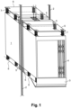
- Fig. 1 shows a first embodiment of the protective frame 6.
- the protective frame 6 comprises a top protective frame and a bottom protective frame.
- the top protective frame is arranged on the top side of the elevator cabin and extends along the top edge of the elevator cabin to form the top protective element.
- the bottom protective frame is arranged on the bottom side of the elevator cabin and extends along the bottom edge of the elevator cabin to form the bottom protective element.
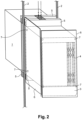
- Fig. 2 shows a second embodiment of the protective frame 6.
- the protective frame 6 comprises a lateral protective frame arranged on the lateral side of the elevator cabin.
- the lateral protective frame comprises the top protective element and the bottom protective element.
- the lateral protective frame extends from (above the top edge) to (below) the bottom edge.
- the top protective element is arranged at the top of the lateral protective frame 6 and the bottom protective element at the bottom of the lateral protective frame 6.
- the lateral protective frame comprises a plurality of lateral sub-frames arranged on different lateral sides of the elevator cabin.
- the different lateral sub-frames can be fixed independently (with distinct shock-absorbing sub-systems) to the elevator cabin. However, it is also possible that the different lateral sub-frames are structurally connected.
- the lateral protective frame comprises a first lateral protective frame arranged at the first lateral side, a second lateral protective frame arranged at the second lateral side, a third lateral protective frame arranged at the third lateral side and/or a fourth lateral protective frame arranged at the fourth lateral side.
- the protective frame comprises preferably a first portion protective frame arranged on the first portion of the elevator cabin and a second portion protective frame arranged on the second portion of the elevator cabin.
- the elevator cabin has then a first portion top protective frame arranged on the top side of the first portion of the elevator cabin, a first portion bottom protective frame arranged on the bottom side of the first portion of the elevator cabin, a second portion top protective frame arranged on the top side of the second portion of the elevator cabin and a second portion bottom protective frame arranged on the bottom side of the second portion of the elevator cabin.
- Fig. 1 the elevator cabin has then a first portion top protective frame arranged on the top side of the first portion of the elevator cabin, a first portion bottom protective frame arranged on the bottom side of the first portion of the elevator cabin, a second portion top protective frame arranged on the top side of the second portion of the elevator cabin and a second portion bottom protective frame arranged on the bottom side of the second portion of the elevator cabin.
- the second lateral protective frame would then have a first portion second lateral protective frame arranged on the first portion of the second lateral side and a second portion second lateral protective frame arranged on the second portion of the second lateral side (not shown).
- the fourth lateral protective frame would then have a first portion fourth lateral protective frame arranged on the first portion of the fourth lateral side (not shown) and a second portion fourth lateral protective frame arranged on the second portion of the fourth lateral side (not shown).
- the top protective element protects more than 50%, preferably more than 60%, preferably more than 70%, preferably more than 80%, preferably more than 90%, preferably more than 95%, preferably 100% of the (peripheral) top edge of the elevator cabin. This means that the top protective element extends along the respective percentage of the top edge.
- the bottom protective element protects more than 50%, preferably more than 60%, preferably more than 70%, preferably more than 80%, preferably more than 90%, preferably more than 95%, preferably 100% of the (peripheral) bottom edge of the elevator cabin. This means that the top protective element extends along the respective percentage of the bottom edge.
- the top protective element extends (only or at least) along the complete risk top edge
- the bottom protective element extends (only or at least) along the complete risk bottom edge.
- the risk (top/bottom) edge is defined as the part of the (top/bottom) edge passing an opening of the pathway of the elevator which allows to invade the pathway of the elevator from the outside.
- the collision detector is configured to detecting when the protective structure 6 is moved out of its operating position to detect a collision.
- This can be for example realized by a mechanical switch which is activated, when the protective structure moves towards the elevator cabin.
- any other detector for detecting that the protective structure is moved out of its operation position is possible to detect a collision.
- the protective system comprises preferably further an electronic detector 10 configured to detect a penetration of an object through the surface spanned between the top edge and the bottom edge.
- This surface provides the lateral envelop of the elevator cabin so that the electronic detector 10 protects the lateral envelop of the elevator cabin from its penetration by an object.
- the object can come from the inside of the elevator cabin or from outside of the pathway.
- the electronic detector is based preferably on the emission of electromagnetic waves.
- the radiation frequency can be in the spectrum of the visible light, infrared light, radar, etc.
- the electronic detector 10 comprises preferably a detector unit and a counter detector unit.
- the detector unit emits preferably the electromagnetic waves.
- the electromagnetic waves are preferably emitted such that they do principally extend in the detection surface.
- the electronic detector, the detector unit and/or the counter detector unit along lateral edges, wherein the lateral edges are formed by the edges between two neighboring lateral sides.
- the electronic detector 10 must be distinguished from the inner electronic detector. While the electronic detector 10 provides a protection from objects entering in the pathway of the elevator from the outside of the elevator, the inner electronic detector protects against objects approaching the entrance of the elevator cabin from the inside.
- FIG. 5 shows an example, in which the electronic detector 10 or one of the detector unit and the counter detector unit is installed on the top protective element (extending along the top protective element) and the electronic detector 10 or the other one of the detector unit and the counter detector unit is installed on the bottom protective element (extending along the bottom protective element).
- the top/bottom protective element or at least the electronic detector 10 installed on them extends therefore beyond the peripheral top/bottom edge of the elevator cabin so that a line/surface of sight is created between the detector unit and the counter detector unit on the top and bottom protective element.
- an electronic "curtain" or envelop is created around the elevator cabin which detects any penetration of this curtain/envelop. It is however also possible to arrange the electronic detector along the lateral frame elements of the lateral protective frame of Fig. 2 so that the electronic curtain is spanned in between the lateral frame elements extending from the top edge or top protective element to the bottom edge or bottom protective element.
Landscapes
- Engineering & Computer Science (AREA)
- Civil Engineering (AREA)
- Mechanical Engineering (AREA)
- Structural Engineering (AREA)
- Cage And Drive Apparatuses For Elevators (AREA)
Claims (12)
- Aufzugskabine (1) eines Aufzugs. Die Aufzugskabine umfasst (1)eine Oberseite,eine Unterseite,eine Querseite,eine Oberkante zwischen der Querseite und der Oberseite,eine Unterkante zwischen der Querseite und der Unterseite,eine Schutzstruktur (6), die mit der Aufzugskabine (1) über ein stoßdämpfendes System (7) verbunden ist, das die Schutzstruktur (6) in einer Betriebsposition hält und der Schutzstruktur (6) ermöglicht, sich entgegen der Fahrtrichtung der Aufzugskabine (1) zu bewegen, wenn die Schutzstruktur (6) während der Fahrt des Aufzugs auf ein Objekt trifft, wobei die Schutzstruktur (6) ein oberes Schutzelement aufweist, das in der Betriebsposition oberhalb der Oberkante angeordnet ist und sich entlang der Oberkante erstreckt, wobei die Schutzstruktur (6) ein unteres Schutzelement aufweist, das in der Betriebsposition unterhalb der Unterkante angeordnet ist und sich entlang der Unterkante erstreckt,einen Kollisionsdetektor zur Feststellung, wenn die Schutzstruktur (6) aus ihrer Betriebsposition bewegt wird, um eine Kollision zu erkennen, wobei der Kollisionsdetektor so konfiguriert ist, dass der Halt der Aufzugskabine (1) während ihrer Fahrt eingeleitet wird, wenn die Kollision erkannt wird.Dies ist dadurch gekennzeichnet, dassdie Schutzstruktur (6) so ausgelegt ist, dass sie einen zentralen Abschnitt der Oberseite frei hält, um einer Person zu ermöglichen, auf der Oberseite der Aufzugskabine (1) zu stehen, ohne dass die Schutzstruktur (6) aus ihrer Betriebsposition bewegt wird, und dassdie Aufzugskabine (1) einen elektronischen Detektor (10) umfasst, der so konfiguriert ist, dass er ein Eindringen eines Objekts durch die Oberfläche, die sich zwischen der Oberkante und der Unterkante erstreckt, zu erkennen.
- Aufzugskabine (1) gemäß der vorhergehenden Angabe, wobei der elektronische Detektor (10) an der Schutzstruktur (6) angeordnet und so konfiguriert ist, dass ein Eindringen eines Objekts durch die sich zwischen dem oberen Schutzelement und dem unteren Schutzelement erstreckende Fläche erkannt wird.
- Aufzugskabine (1) gemäß der vorhergehenden Angabe, wobei ein Sender des Lichtvorhangs entlang eines der oberen und unteren Schutzelemente angeordnet ist und ein Empfänger oder Reflektor an dem anderen der oberen und unteren Schutzelemente angeordnet ist.
- Aufzugskabine (1) gemäß einer der vorhergehenden Angaben. Die Aufzugskabine umfasst (1) einen Kabinenrahmen (5), der sich im Zentrum der Kabine um die Kabine herum erstreckt und ein Befestigungsmittel zur Befestigung der Aufzugskabine an einem Aufzugskabel oder an einem Hydraulikkolben und zum Halten des Kabinengehäuses aufweist, der für das Tragen der Fahrgäste oder einer anderen Gewichtslast konfiguriert ist, wobei der Kabinenrahmen (5) die Aufzugskabine in einem ersten Abschnitt mit einer Querseite (erster Abschnitt), einer Oberseite (erster Abschnitt), einer Unterseite (erster Abschnitt), einer Oberkante (erster Abschnitt) und einer Unterkante (erster Abschnitt) trennt und in einem zweiten Abschnitt mit einer Querseite (zweiter Abschnitt), einer Oberseite (zweiter Abschnitt), einer Unterseite (zweiter Abschnitt), einer Oberkante (zweiter Abschnitt) und einer Unterkante (zweiter Abschnitt), wobei die Schutzstruktur (6) eine Schutzstruktur (erster Abschnitt) und eine Schutzstruktur (zweiter Abschnitt) (6) umfasst, wobei die Schutzstruktur (erster Abschnitt) (6) über ein Stoßdämpfersystem (erster Abschnitt) (7) mit der Aufzugskabine verbunden ist, das die Schutzstruktur (6) des ersten Abschnitts in einer Betriebsposition (erster Abschnitt) hält und der Schutzstruktur (6) des ersten Abschnitts ermöglicht, sich entgegen der Fahrtrichtung der Aufzugskabine zu bewegen, wenn die Schutzstruktur (6) des ersten Abschnitts während der Fahrt der Aufzugskabine auf ein Objekt trifft, wobei die Schutzstruktur (6) des ersten Abschnitts ein oberes Schutzelement des ersten Abschnitts aufweist, das in der Betriebsposition über der oberen Kante des ersten Abschnitts angeordnet ist und sich entlang der oberen Kante des ersten Abschnitts erstreckt, wobei die Schutzstruktur (6) des ersten Abschnitts ein unteres Schutzelement (erster Abschnitt) aufweist, das in der Betriebsposition (erster Abschnitt) unterhalb der Unterkante (erster Abschnitt) angeordnet ist und sich entlang der Unterkante (erster Abschnitt) erstreckt, wobei die Schutzstruktur (6) des zweiten Abschnitts über ein Stoßdämpfersystem (7) des zweiten Abschnitts mit der Aufzugskabine verbunden ist, das die Schutzstruktur (6) des zweiten Abschnitts in einer Betriebsposition des zweiten Abschnitts hält und der Schutzstruktur (6) des zweiten Abschnitts ermöglicht, sich entgegen der Fahrtrichtung des Aufzugskabine zu bewegen, wenn die Schutzstruktur des zweiten Abschnitts während der Fahrt der Aufzugskabine auf ein Objekt trifft, wobei die Schutzstruktur des zweiten Abschnitts ein oberes Schutzelement des zweiten Abschnitts aufweist, das in der Betriebsposition oberhalb der oberen Kante des zweiten Abschnitts angeordnet ist und sich entlang der Oberkante des zweiten Abschnitts erstreckt, wobei die Schutzstruktur des zweiten Abschnitts ein unteres Schutzelement des zweiten Abschnitts aufweist, das in der Betriebsposition des zweiten Abschnitts unterhalb der Unterkante des zweiten Abschnitts angeordnet ist und sich entlang der Unterkante des zweiten Abschnitts erstreckt.
- Aufzugskabine (1) gemäß einer der vorhergehenden Angaben. Die Schutzstruktur (6) umfasst eine obere Schutzstruktur (6), die an der Oberseite angeordnet ist, und eine untere Schutzstruktur (6), die an der Unterseite angeordnet ist, wobei die obere Schutzstruktur (6) mit der Aufzugskabine (1) über ein oberes stoßdämpfendes System (7) verbunden ist, das die obere Schutzstruktur (6) in einer oberen Betriebsposition hält und der oberen Schutzstruktur (6) ermöglicht, sich entgegen der Fahrtrichtung der Aufzugskabine (1) zu bewegen, wenn die obere Schutzstruktur (6) während der Fahrt der Aufzugskabine (1) auf ein Objekt trifft, wobei die obere Schutzstruktur (6) das obere Schutzelement umfasst und die untere Schutzstruktur (6) über ein unteres Stoßdämpfersystem mit der Aufzugskabine (1) verbunden ist, das die untere Schutzstruktur (6) in einer unteren Betriebsposition hält und der unteren Schutzstruktur (6) ermöglicht, sich entgegen der Fahrtrichtung der Aufzugskabine (1) zu bewegen, wenn die untere Schutzstruktur (6) während der Fahrt der Aufzugskabine (1) auf ein Objekt trifft, wobei die untere Schutzstruktur (6) das untere Schutzelement umfasst.
- Aufzugskabine (1) gemäß einer der Angaben 1 bis 5, wobei die Schutzstruktur (6) eine seitliche Schutzstruktur (6) umfasst, die an der Querseite angeordnet ist, und die seitliche Schutzstruktur (6) das obere Schutzelement und das untere Schutzelement umfasst.
- Aufzugskabine (1) gemäß einer der vorhergehenden Angaben, wobei das Stoßdämpfersystem (7) und die Schutzstruktur (6) so konfiguriert sind, dass sich die Schutzstruktur (6) bei einer Kollision mit einem Objekt eine absorbierende Distanz entgegen der Bewegungsrichtung der Aufzugskabine (1) bewegen kann, wobei die absorbierende Distanz mindestens 2 cm beträgt.
- Aufzugskabine (1) gemäß einer der vorhergehenden Angaben,wobei das obere Schutzelement eine Rahmenbreite von weniger als 10 cm aufweist und die Rahmenbreite der Abmessung des oberen Schutzelements (senkrecht zur Fahrtrichtung und senkrecht zur Oberkante) entspricht und/oderdas untere Schutzelement eine Rahmenbreite von weniger als 10 cm aufweist und die Rahmenbreite der Abmessung des unteren Schutzelements (senkrecht zur Fahrtrichtung und senkrecht zur Unterkante) entspricht.
- Aufzug, der eine Aufzugskabine (1) gemäß einer der vorhergehenden Angaben und einen Aufzugsweg umfasst, in dem sich die Aufzugskabine (1) auf und ab bewegen kann, wobei der Aufzug so ausgelegt ist, dass er während der Fahrt der Aufzugskabine (1) in dem Aufzugsweg mindestens eine Öffnung aufweist, durch die ein Objekt in den Aufzugweg eintreten und mit der Aufzugskabine (1) kollidieren kann, wobei die gefährdete Oberkante der Teil der Oberkante ist, der diese (mindestens eine) Öffnung während der Fahrt passiert, und die gefährdete Unterkante der Teil der Unterkante ist, der diese (mindestens eine) Öffnung während der Fahrt passiert, wobei sich das obere Schutzelement entlang der gesamten gefährdeten Oberkante erstreckt, während sich das untere Schutzelement entlang der gesamten gefährdeten Unterkante erstreckt.
- Aufzug gemäß der vorhergehenden Angabe, der ein Gegengewicht aufweist, wobei das Gegengewicht eine Oberseite, eine Unterseite, eine Querseite, eine Oberkante zwischen der Querseite und der Oberseite und eine Unterkante zwischen der Querseite und der Unterseite umfasst, während das System eine Schutzstruktur (6) und ein Stoßdämpfersystem (7) umfasst, wobei die Schutzstruktur (6) über das Stoßdämpfersystem (7), das die Schutzstruktur (6) in einer Betriebsposition hält, mit dem Gegengewicht verbunden ist und der Schutzstruktur (6) ermöglicht wird, sich entgegen der Fahrtrichtung des Gegengewichts zu bewegen, wenn die Schutzstruktur (6) während der Fahrt des Aufzugs auf ein Objekt trifft, wobei die Schutzstruktur (6) ein oberes Schutzelement aufweist, das in der Betriebsposition oberhalb der Oberkante angeordnet ist und sich entlang der Oberkante erstreckt, wobei die Schutzstruktur (6) ein unteres Schutzelement aufweist, das in der Betriebsposition unterhalb der Unterkante angeordnet ist und sich entlang der Unterkante erstreckt. Zudem umfasst das System einen Kollisionsdetektor für die Feststellung, wenn die Schutzstruktur (6) aus ihrer Betriebsposition bewegt wird, um eine Kollision zu erkennen.
- Aufzug gemäß Angabe 9 oder 10, wobei das Stoßdämpfersystem (7) der Aufzugskabine (1) so konfiguriert ist, dass sich die Schutzstruktur (6) bei einer Kollision mit einem Objekt mindestens eine absorbierende Distanz entgegen der Bewegungsrichtung der Aufzugskabine bewegen kann, während die absorbierende Distanz länger ist als die Distanz der Aufzugskabine, die zum Anhalten erforderlich ist, wenn die Kollision mithilfe des Kollisionsdetektors der Aufzugskabine erkannt wird.
- System zum Schutz einer Aufzugskabine (1) eines Aufzugs, bei dem die Aufzugskabine (1) eine Oberseite, eine Unterseite, eine Querseite, eine Oberkante zwischen der Querseite und der Oberseite sowie eine Unterkante zwischen der Querseite und der Unterseite umfasst, wobei das System eine Schutzstruktur (6) und ein Stoßdämpfersystem (7) umfasst, wobei die Schutzstruktur (6) mit der Aufzugskabine (1) über das Stoßdämpfersystem (7) verbunden ist, das die Schutzstruktur (6) in einer Betriebsposition hält und der Schutzstruktur (6) ermöglicht, sich entgegen der Fahrtrichtung der Aufzugskabine (1) zu bewegen, wenn die Schutzstruktur (6) während der Fahrt des Aufzugs auf ein Objekt trifft, wobei die Schutzstruktur (6) ein oberes Schutzelement aufweist, das in der Betriebsposition oberhalb der Oberkante angeordnet ist und sich entlang der Oberkante erstreckt, während die Schutzstruktur (6) ein unteres Schutzelement aufweist, das in der Betriebsposition unterhalb der Unterkante angeordnet ist und sich entlang der Unterkante erstreckt. Zudem umfasst das System einen Kollisionsdetektor, der erkennt, wenn die Schutzstruktur (6) aus ihrer Betriebsposition bewegt wird, um eine Kollision zu erkennen;
dies ist dadurch gekennzeichnet, dass
die Schutzstruktur (6) so ausgelegt ist, dass sich das obere Schutzelement entlang der Oberkante erstreckt, und dass das System ferner einen elektronischen Detektor (10) umfasst, der so konfiguriert ist, dass ein Eindringen eines Objekts durch die Oberfläche, die sich zwischen der Oberkante und der Unterkante erstreckt, erkannt wird.
Priority Applications (1)
| Application Number | Priority Date | Filing Date | Title |
|---|---|---|---|
| HUE21844197A HUE072929T2 (hu) | 2021-12-10 | 2021-12-10 | Védelmi rendszer felvonókhoz |
Applications Claiming Priority (1)
| Application Number | Priority Date | Filing Date | Title |
|---|---|---|---|
| PCT/EP2021/085245 WO2023104318A1 (en) | 2021-12-10 | 2021-12-10 | Protection system for elevators |
Publications (2)
| Publication Number | Publication Date |
|---|---|
| EP4440974A1 EP4440974A1 (de) | 2024-10-09 |
| EP4440974B1 true EP4440974B1 (de) | 2025-07-02 |
Family
ID=79686951
Family Applications (1)
| Application Number | Title | Priority Date | Filing Date |
|---|---|---|---|
| EP21844197.0A Active EP4440974B1 (de) | 2021-12-10 | 2021-12-10 | Aufzugsschutzsystem |
Country Status (4)
| Country | Link |
|---|---|
| US (1) | US20250059002A1 (de) |
| EP (1) | EP4440974B1 (de) |
| HU (1) | HUE072929T2 (de) |
| WO (1) | WO2023104318A1 (de) |
Family Cites Families (19)
| Publication number | Priority date | Publication date | Assignee | Title |
|---|---|---|---|---|
| CN106744177A (zh) * | 2016-11-25 | 2017-05-31 | 吴江骏达电梯部件有限公司 | 一种新型多功能电梯用安全轿厢 |
| CN108249259B (zh) * | 2016-12-29 | 2021-05-28 | 通力股份公司 | 电梯 |
| KR101976607B1 (ko) * | 2017-11-28 | 2019-05-09 | 공주대학교 산학협력단 | 안전성을 향상시킨 승강기용 충격흡수장치 |
| EP3502034A1 (de) * | 2017-12-19 | 2019-06-26 | KONE Corporation | Aufzuggegengewichtsanordnung |
| CN108622774A (zh) * | 2018-07-06 | 2018-10-09 | 苏州福特美福电梯有限公司 | 一种电梯轿厢的减震装置 |
| CN210558710U (zh) * | 2019-06-28 | 2020-05-19 | 东南电梯股份有限公司 | 无井道电梯运行空间安全保护系统 |
| CN110436290A (zh) | 2019-06-28 | 2019-11-12 | 东南电梯股份有限公司 | 无井道电梯运行空间安全保护系统 |
| CN110371830A (zh) * | 2019-08-16 | 2019-10-25 | 南通勇振机电有限公司 | 一种稳定的电梯轿底减震装置 |
| CN213011400U (zh) | 2020-03-04 | 2021-04-20 | 苏州多美适家用电梯有限公司 | 一种无井道智能家用电梯安全运行空间保护装置 |
| CN111170112A (zh) | 2020-03-04 | 2020-05-19 | 苏州多美适家用电梯有限公司 | 一种无井道智能家用电梯安全运行空间保护装置 |
| CN111232802B (zh) * | 2020-03-05 | 2021-06-08 | 广州鼎力金属制品有限公司 | 一种电梯轿厢 |
| CN111362107A (zh) * | 2020-04-11 | 2020-07-03 | 田广申 | 多功能安全的电梯厢体 |
| CN111847200A (zh) * | 2020-07-13 | 2020-10-30 | 湖北铜都通用电梯有限公司 | 一种新型轿厢 |
| CN112141857A (zh) * | 2020-08-20 | 2020-12-29 | 浙江益仓机电有限公司 | 一种带内饰结构的电梯轿箱 |
| CN213864918U (zh) * | 2020-11-30 | 2021-08-03 | 苏州博恩电梯有限公司 | 一种无井道电梯运行空间安全保护系统 |
| CN112707268A (zh) * | 2020-12-22 | 2021-04-27 | 住友富士电梯有限公司 | 一种安全防护性好的升降式电梯 |
| CN112707283A (zh) * | 2020-12-22 | 2021-04-27 | 住友富士电梯有限公司 | 便于检修的电梯 |
| CN116424991A (zh) * | 2023-04-10 | 2023-07-14 | 深圳市追风马科技有限公司 | 一种电梯轿厢的安全装置 |
| CN221565412U (zh) * | 2023-11-14 | 2024-08-20 | 沈阳远大智能工业集团股份有限公司 | 一种电梯轿顶检修防护报警装置 |
-
2021
- 2021-12-10 EP EP21844197.0A patent/EP4440974B1/de active Active
- 2021-12-10 HU HUE21844197A patent/HUE072929T2/hu unknown
- 2021-12-10 US US18/718,349 patent/US20250059002A1/en active Pending
- 2021-12-10 WO PCT/EP2021/085245 patent/WO2023104318A1/en not_active Ceased
Also Published As
| Publication number | Publication date |
|---|---|
| HUE072929T2 (hu) | 2025-12-28 |
| US20250059002A1 (en) | 2025-02-20 |
| EP4440974A1 (de) | 2024-10-09 |
| WO2023104318A1 (en) | 2023-06-15 |
Similar Documents
| Publication | Publication Date | Title |
|---|---|---|
| CN1251957C (zh) | 电梯门的安全装置及其运行方法 | |
| SG193488A1 (en) | Elevator having a minimal elevator shaft well depth and a permanent protective space | |
| RU2234450C2 (ru) | Лифт и устройство временного ограничения хода кабины или противовеса для лифта | |
| US10029885B2 (en) | Elevator | |
| KR101531701B1 (ko) | 관절형 플랫폼 스크린도어 | |
| US20250059002A1 (en) | Protection system for elevators | |
| KR101747682B1 (ko) | 안전 기능을 강화한 승강기 | |
| US20210269284A1 (en) | System for controlling a service access associated with an elevator car | |
| JP2018095457A (ja) | エレベーター装置 | |
| JP6381401B2 (ja) | 可動柵 | |
| AU2019295892B2 (en) | Lift system with a protective screen | |
| JP6157962B2 (ja) | エレベータ装置 | |
| US6615953B1 (en) | Construction hoist with optical monitoring device | |
| EP3328776A1 (de) | Kabinentür für einen aufzug | |
| CN105384017A (zh) | 电梯装置 | |
| JP6275812B1 (ja) | エレベータ装置 | |
| JP3929370B2 (ja) | エレベーターの乗場装置 | |
| NL9100059A (nl) | Beveiligingsinrichting voor een lift. | |
| CN107857177B (zh) | 一种电梯防撞装置 | |
| US12552640B2 (en) | Drive unit placement and access openings for a platform lifting system | |
| JP6026633B1 (ja) | エレベータ装置 | |
| EP4082956A1 (de) | Aufzugstür mit türschutzanordnung | |
| JPH0978872A (ja) | 駐車設備の安全装置 | |
| JP2019099149A (ja) | 乗客及び障害物検知機能を含む電車プラットフォーム安全装置 | |
| HK40035584A (en) | Lift system with a protective screen |
Legal Events
| Date | Code | Title | Description |
|---|---|---|---|
| STAA | Information on the status of an ep patent application or granted ep patent |
Free format text: STATUS: UNKNOWN |
|
| STAA | Information on the status of an ep patent application or granted ep patent |
Free format text: STATUS: THE INTERNATIONAL PUBLICATION HAS BEEN MADE |
|
| PUAI | Public reference made under article 153(3) epc to a published international application that has entered the european phase |
Free format text: ORIGINAL CODE: 0009012 |
|
| STAA | Information on the status of an ep patent application or granted ep patent |
Free format text: STATUS: REQUEST FOR EXAMINATION WAS MADE |
|
| 17P | Request for examination filed |
Effective date: 20240329 |
|
| AK | Designated contracting states |
Kind code of ref document: A1 Designated state(s): AL AT BE BG CH CY CZ DE DK EE ES FI FR GB GR HR HU IE IS IT LI LT LU LV MC MK MT NL NO PL PT RO RS SE SI SK SM TR |
|
| GRAP | Despatch of communication of intention to grant a patent |
Free format text: ORIGINAL CODE: EPIDOSNIGR1 |
|
| STAA | Information on the status of an ep patent application or granted ep patent |
Free format text: STATUS: GRANT OF PATENT IS INTENDED |
|
| GRAS | Grant fee paid |
Free format text: ORIGINAL CODE: EPIDOSNIGR3 |
|
| DAV | Request for validation of the european patent (deleted) | ||
| DAX | Request for extension of the european patent (deleted) | ||
| INTG | Intention to grant announced |
Effective date: 20250123 |
|
| RBV | Designated contracting states (corrected) |
Designated state(s): AL AT BG CH CY CZ DE DK EE ES FI FR GB GR HR HU IE IS IT LI LT LU LV MC MK MT NL NO PL PT RO RS SE SI SK SM TR |
|
| GRAA | (expected) grant |
Free format text: ORIGINAL CODE: 0009210 |
|
| STAA | Information on the status of an ep patent application or granted ep patent |
Free format text: STATUS: THE PATENT HAS BEEN GRANTED |
|
| AK | Designated contracting states |
Kind code of ref document: B1 Designated state(s): AL AT BG CH CY CZ DE DK EE ES FI FR GB GR HR HU IE IS IT LI LT LU LV MC MK MT NL NO PL PT RO RS SE SI SK SM TR |
|
| REG | Reference to a national code |
Ref country code: GB Ref legal event code: FG4D |
|
| REG | Reference to a national code |
Ref country code: CH Ref legal event code: EP |
|
| REG | Reference to a national code |
Ref country code: DE Ref legal event code: R096 Ref document number: 602021033534 Country of ref document: DE |
|
| REG | Reference to a national code |
Ref country code: IE Ref legal event code: FG4D |
|
| REG | Reference to a national code |
Ref country code: NL Ref legal event code: MP Effective date: 20250702 |
|
| PG25 | Lapsed in a contracting state [announced via postgrant information from national office to epo] |
Ref country code: PT Free format text: LAPSE BECAUSE OF FAILURE TO SUBMIT A TRANSLATION OF THE DESCRIPTION OR TO PAY THE FEE WITHIN THE PRESCRIBED TIME-LIMIT Effective date: 20251103 |
|
| PG25 | Lapsed in a contracting state [announced via postgrant information from national office to epo] |
Ref country code: NL Free format text: LAPSE BECAUSE OF FAILURE TO SUBMIT A TRANSLATION OF THE DESCRIPTION OR TO PAY THE FEE WITHIN THE PRESCRIBED TIME-LIMIT Effective date: 20250702 |
|
| REG | Reference to a national code |
Ref country code: AT Ref legal event code: MK05 Ref document number: 1809081 Country of ref document: AT Kind code of ref document: T Effective date: 20250702 |
|
| REG | Reference to a national code |
Ref country code: HU Ref legal event code: AG4A Ref document number: E072929 Country of ref document: HU |
|
| REG | Reference to a national code |
Ref country code: CH Ref legal event code: U11 Free format text: ST27 STATUS EVENT CODE: U-0-0-U10-U11 (AS PROVIDED BY THE NATIONAL OFFICE) Effective date: 20260101 |
|
| PG25 | Lapsed in a contracting state [announced via postgrant information from national office to epo] |
Ref country code: IS Free format text: LAPSE BECAUSE OF FAILURE TO SUBMIT A TRANSLATION OF THE DESCRIPTION OR TO PAY THE FEE WITHIN THE PRESCRIBED TIME-LIMIT Effective date: 20251102 |
|
| PGFP | Annual fee paid to national office [announced via postgrant information from national office to epo] |
Ref country code: GB Payment date: 20251216 Year of fee payment: 5 |
|
| PG25 | Lapsed in a contracting state [announced via postgrant information from national office to epo] |
Ref country code: NO Free format text: LAPSE BECAUSE OF FAILURE TO SUBMIT A TRANSLATION OF THE DESCRIPTION OR TO PAY THE FEE WITHIN THE PRESCRIBED TIME-LIMIT Effective date: 20251002 |
|
| REG | Reference to a national code |
Ref country code: LT Ref legal event code: MG9D |
|
| PG25 | Lapsed in a contracting state [announced via postgrant information from national office to epo] |
Ref country code: AT Free format text: LAPSE BECAUSE OF FAILURE TO SUBMIT A TRANSLATION OF THE DESCRIPTION OR TO PAY THE FEE WITHIN THE PRESCRIBED TIME-LIMIT Effective date: 20250702 |
|
| PG25 | Lapsed in a contracting state [announced via postgrant information from national office to epo] |
Ref country code: FI Free format text: LAPSE BECAUSE OF FAILURE TO SUBMIT A TRANSLATION OF THE DESCRIPTION OR TO PAY THE FEE WITHIN THE PRESCRIBED TIME-LIMIT Effective date: 20250702 |
|
| PGFP | Annual fee paid to national office [announced via postgrant information from national office to epo] |
Ref country code: IT Payment date: 20251215 Year of fee payment: 5 |
|
| PG25 | Lapsed in a contracting state [announced via postgrant information from national office to epo] |
Ref country code: HR Free format text: LAPSE BECAUSE OF FAILURE TO SUBMIT A TRANSLATION OF THE DESCRIPTION OR TO PAY THE FEE WITHIN THE PRESCRIBED TIME-LIMIT Effective date: 20250702 |
|
| PGFP | Annual fee paid to national office [announced via postgrant information from national office to epo] |
Ref country code: HU Payment date: 20251128 Year of fee payment: 5 Ref country code: FR Payment date: 20251216 Year of fee payment: 5 |
|
| PG25 | Lapsed in a contracting state [announced via postgrant information from national office to epo] |
Ref country code: GR Free format text: LAPSE BECAUSE OF FAILURE TO SUBMIT A TRANSLATION OF THE DESCRIPTION OR TO PAY THE FEE WITHIN THE PRESCRIBED TIME-LIMIT Effective date: 20251003 |
|
| PG25 | Lapsed in a contracting state [announced via postgrant information from national office to epo] |
Ref country code: SE Free format text: LAPSE BECAUSE OF FAILURE TO SUBMIT A TRANSLATION OF THE DESCRIPTION OR TO PAY THE FEE WITHIN THE PRESCRIBED TIME-LIMIT Effective date: 20250702 |
|
| PGFP | Annual fee paid to national office [announced via postgrant information from national office to epo] |
Ref country code: CZ Payment date: 20251126 Year of fee payment: 5 |
|
| PG25 | Lapsed in a contracting state [announced via postgrant information from national office to epo] |
Ref country code: LV Free format text: LAPSE BECAUSE OF FAILURE TO SUBMIT A TRANSLATION OF THE DESCRIPTION OR TO PAY THE FEE WITHIN THE PRESCRIBED TIME-LIMIT Effective date: 20250702 |
|
| PG25 | Lapsed in a contracting state [announced via postgrant information from national office to epo] |
Ref country code: PL Free format text: LAPSE BECAUSE OF FAILURE TO SUBMIT A TRANSLATION OF THE DESCRIPTION OR TO PAY THE FEE WITHIN THE PRESCRIBED TIME-LIMIT Effective date: 20250702 Ref country code: BG Free format text: LAPSE BECAUSE OF FAILURE TO SUBMIT A TRANSLATION OF THE DESCRIPTION OR TO PAY THE FEE WITHIN THE PRESCRIBED TIME-LIMIT Effective date: 20250702 |
|
| PG25 | Lapsed in a contracting state [announced via postgrant information from national office to epo] |
Ref country code: RS Free format text: LAPSE BECAUSE OF FAILURE TO SUBMIT A TRANSLATION OF THE DESCRIPTION OR TO PAY THE FEE WITHIN THE PRESCRIBED TIME-LIMIT Effective date: 20251002 |
|
| PG25 | Lapsed in a contracting state [announced via postgrant information from national office to epo] |
Ref country code: ES Free format text: LAPSE BECAUSE OF FAILURE TO SUBMIT A TRANSLATION OF THE DESCRIPTION OR TO PAY THE FEE WITHIN THE PRESCRIBED TIME-LIMIT Effective date: 20250702 |
|
| PG25 | Lapsed in a contracting state [announced via postgrant information from national office to epo] |
Ref country code: RO Free format text: LAPSE BECAUSE OF FAILURE TO SUBMIT A TRANSLATION OF THE DESCRIPTION OR TO PAY THE FEE WITHIN THE PRESCRIBED TIME-LIMIT Effective date: 20250702 |
|
| PG25 | Lapsed in a contracting state [announced via postgrant information from national office to epo] |
Ref country code: SM Free format text: LAPSE BECAUSE OF FAILURE TO SUBMIT A TRANSLATION OF THE DESCRIPTION OR TO PAY THE FEE WITHIN THE PRESCRIBED TIME-LIMIT Effective date: 20250702 |
|
| PG25 | Lapsed in a contracting state [announced via postgrant information from national office to epo] |
Ref country code: DK Free format text: LAPSE BECAUSE OF FAILURE TO SUBMIT A TRANSLATION OF THE DESCRIPTION OR TO PAY THE FEE WITHIN THE PRESCRIBED TIME-LIMIT Effective date: 20250702 |
|
| PGFP | Annual fee paid to national office [announced via postgrant information from national office to epo] |
Ref country code: DE Payment date: 20251222 Year of fee payment: 5 |
|
| PGFP | Annual fee paid to national office [announced via postgrant information from national office to epo] |
Ref country code: CH Payment date: 20260101 Year of fee payment: 5 |
|
| PG25 | Lapsed in a contracting state [announced via postgrant information from national office to epo] |
Ref country code: SK Free format text: LAPSE BECAUSE OF FAILURE TO SUBMIT A TRANSLATION OF THE DESCRIPTION OR TO PAY THE FEE WITHIN THE PRESCRIBED TIME-LIMIT Effective date: 20250702 Ref country code: EE Free format text: LAPSE BECAUSE OF FAILURE TO SUBMIT A TRANSLATION OF THE DESCRIPTION OR TO PAY THE FEE WITHIN THE PRESCRIBED TIME-LIMIT Effective date: 20250702 |
|
| PLBE | No opposition filed within time limit |
Free format text: ORIGINAL CODE: 0009261 |
|
| STAA | Information on the status of an ep patent application or granted ep patent |
Free format text: STATUS: NO OPPOSITION FILED WITHIN TIME LIMIT |