EP4440221A1 - Drahtloses erfassungsverfahren und vorrichtung sowie netzwerkseitige vorrichtung - Google Patents
Drahtloses erfassungsverfahren und vorrichtung sowie netzwerkseitige vorrichtung Download PDFInfo
- Publication number
- EP4440221A1 EP4440221A1 EP22897728.6A EP22897728A EP4440221A1 EP 4440221 A1 EP4440221 A1 EP 4440221A1 EP 22897728 A EP22897728 A EP 22897728A EP 4440221 A1 EP4440221 A1 EP 4440221A1
- Authority
- EP
- European Patent Office
- Prior art keywords
- information
- sensing signal
- sensing
- target
- wireless sensing
- Prior art date
- Legal status (The legal status is an assumption and is not a legal conclusion. Google has not performed a legal analysis and makes no representation as to the accuracy of the status listed.)
- Pending
Links
Images


Classifications
-
- H—ELECTRICITY
- H04—ELECTRIC COMMUNICATION TECHNIQUE
- H04B—TRANSMISSION
- H04B17/00—Monitoring; Testing
- H04B17/30—Monitoring; Testing of propagation channels
- H04B17/309—Measuring or estimating channel quality parameters
-
- G—PHYSICS
- G01—MEASURING; TESTING
- G01S—RADIO DIRECTION-FINDING; RADIO NAVIGATION; DETERMINING DISTANCE OR VELOCITY BY USE OF RADIO WAVES; LOCATING OR PRESENCE-DETECTING BY USE OF THE REFLECTION OR RERADIATION OF RADIO WAVES; ANALOGOUS ARRANGEMENTS USING OTHER WAVES
- G01S13/00—Systems using the reflection or reradiation of radio waves, e.g. radar systems; Analogous systems using reflection or reradiation of waves whose nature or wavelength is irrelevant or unspecified
- G01S13/003—Bistatic radar systems; Multistatic radar systems
-
- G—PHYSICS
- G01—MEASURING; TESTING
- G01S—RADIO DIRECTION-FINDING; RADIO NAVIGATION; DETERMINING DISTANCE OR VELOCITY BY USE OF RADIO WAVES; LOCATING OR PRESENCE-DETECTING BY USE OF THE REFLECTION OR RERADIATION OF RADIO WAVES; ANALOGOUS ARRANGEMENTS USING OTHER WAVES
- G01S13/00—Systems using the reflection or reradiation of radio waves, e.g. radar systems; Analogous systems using reflection or reradiation of waves whose nature or wavelength is irrelevant or unspecified
- G01S13/74—Systems using reradiation of radio waves, e.g. secondary radar systems; Analogous systems
- G01S13/75—Systems using reradiation of radio waves, e.g. secondary radar systems; Analogous systems using transponders powered from received waves, e.g. using passive transponders, or using passive reflectors
- G01S13/751—Systems using reradiation of radio waves, e.g. secondary radar systems; Analogous systems using transponders powered from received waves, e.g. using passive transponders, or using passive reflectors wherein the responder or reflector radiates a coded signal
-
- H—ELECTRICITY
- H04—ELECTRIC COMMUNICATION TECHNIQUE
- H04B—TRANSMISSION
- H04B7/00—Radio transmission systems, i.e. using radiation field
- H04B7/22—Scatter propagation systems, e.g. ionospheric, tropospheric or meteor scatter
-
- H—ELECTRICITY
- H04—ELECTRIC COMMUNICATION TECHNIQUE
- H04W—WIRELESS COMMUNICATION NETWORKS
- H04W16/00—Network planning, e.g. coverage or traffic planning tools; Network deployment, e.g. resource partitioning or cells structures
- H04W16/18—Network planning tools
-
- H—ELECTRICITY
- H04—ELECTRIC COMMUNICATION TECHNIQUE
- H04W—WIRELESS COMMUNICATION NETWORKS
- H04W52/00—Power management, e.g. Transmission Power Control [TPC] or power classes
- H04W52/02—Power saving arrangements
- H04W52/0209—Power saving arrangements in terminal devices
- H04W52/0261—Power saving arrangements in terminal devices managing power supply demand, e.g. depending on battery level
-
- G—PHYSICS
- G01—MEASURING; TESTING
- G01S—RADIO DIRECTION-FINDING; RADIO NAVIGATION; DETERMINING DISTANCE OR VELOCITY BY USE OF RADIO WAVES; LOCATING OR PRESENCE-DETECTING BY USE OF THE REFLECTION OR RERADIATION OF RADIO WAVES; ANALOGOUS ARRANGEMENTS USING OTHER WAVES
- G01S7/00—Details of systems according to groups G01S13/00, G01S15/00, G01S17/00
- G01S7/003—Transmission of data between radar, sonar or lidar systems and remote stations
-
- Y—GENERAL TAGGING OF NEW TECHNOLOGICAL DEVELOPMENTS; GENERAL TAGGING OF CROSS-SECTIONAL TECHNOLOGIES SPANNING OVER SEVERAL SECTIONS OF THE IPC; TECHNICAL SUBJECTS COVERED BY FORMER USPC CROSS-REFERENCE ART COLLECTIONS [XRACs] AND DIGESTS
- Y02—TECHNOLOGIES OR APPLICATIONS FOR MITIGATION OR ADAPTATION AGAINST CLIMATE CHANGE
- Y02D—CLIMATE CHANGE MITIGATION TECHNOLOGIES IN INFORMATION AND COMMUNICATION TECHNOLOGIES [ICT], I.E. INFORMATION AND COMMUNICATION TECHNOLOGIES AIMING AT THE REDUCTION OF THEIR OWN ENERGY USE
- Y02D30/00—Reducing energy consumption in communication networks
- Y02D30/70—Reducing energy consumption in communication networks in wireless communication networks
Definitions
- This application pertains to the field of communications technologies, and specifically, relates to a wireless sensing method and apparatus, and a network-side device.
- sensing and communication systems are usually designed separately and occupy different frequency bands.
- Due to wide deployment of millimeter wave and massive multi-input multi-output (Multi Input Multi Output, MIMO) technologies communication signals in future wireless communication systems often have high resolution in time domain and angle domain, which makes it possible to implement high-precision sensing by using communication signals. Therefore, the best way is to jointly design the sensing and communication systems to share same frequency bands and hardware, thereby improving frequency efficiency and reducing hardware costs. This has prompted research on integrated sensing and communication (Integrated Sensing And Communication, ISAC).
- ISAC Integrated Sensing And Communication
- sensing devices with a conventional radio architecture include power-consuming radio frequency links that contain oscillators, mixers, digital-analog converters, and the like. Therefore, the sensing devices are relatively large and batteries have a relatively short service life, which limits the layout of the sensing devices in the ISAC, and further limits sensing performance of the ISAC system.
- Embodiments of this application provide a wireless sensing method and apparatus, and a network-side device, so as to backscatter a target sensing signal by using a first device in an ISAC system, thereby improving sensing performance of the ISAC system.
- a wireless sensing method includes: backscattering, by a first device, a target sensing signal to a wireless sensing signal receive end, where the target sensing signal comes from a wireless sensing signal transmit end, the wireless sensing signal transmit end includes a first terminal or a first network-side device, and the wireless sensing signal receive end includes a second network-side device.
- a wireless sensing apparatus applied to a first device.
- the apparatus includes: a backscattering module, configured to backscatter a target sensing signal to a wireless sensing signal receive end, where the target sensing signal comes from a wireless sensing signal transmit end, the wireless sensing signal transmit end includes a first terminal or a first network-side device, and the wireless sensing signal receive end includes a second network-side device.
- a wireless sensing method includes:
- a wireless sensing apparatus applied to a wireless sensing signal receive end, where the wireless sensing signal receive end includes a second network-side device, and the apparatus includes:
- a wireless sensing method includes:
- a wireless sensing apparatus applied to a second device.
- the apparatus includes:
- a wireless sensing system including: a first device, a wireless sensing signal transmit end, and a wireless sensing signal receive end;
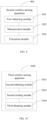
- a network-side device includes a processor and a memory, and a program or instructions capable of running on the processor are stored in the memory.
- the program or the instructions are executed by the processor, the steps of the method according to the third aspect or the fifth aspect are implemented.
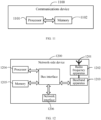
- a network-side device including a processor and a communication interface.
- the communication interface is configured to obtain second information, where the second information includes sensing requirement information and/or target sensing signal related configuration information corresponding to the sensing requirement information; the communication interface is further configured to perform, according to the target sensing signal related configuration information, measurement on a target sensing signal sent by a wireless sensing signal transmit end and at least partially backscattered by a first device, so as to obtain a target measurement quantity, where the wireless sensing signal transmit end includes a first terminal or a first network-side device; and the processor is configured to determine a target sensing result based on the target measurement quantity, or the communication interface configured to send the target measurement quantity; or, in a case that the network-side device is a second device, the communication interface is configured to obtain sensing requirement information and send second information to at least one of the wireless sensing signal transmit end and the wireless sensing signal receive end,
- a wireless sensing system including a terminal and a network-side device, where the network-side device may be configured to execute the steps of the wireless sensing method according to the third aspect and the fifth aspect.
- a readable storage medium where a program or instructions are stored in the readable storage medium; and when the program or the instructions are executed by a processor, the steps of the method according to the first aspect are implemented, or the steps of the method according to the third aspect are implemented, or the steps of the method according to the fifth aspect are implemented.
- a chip is provided, where the chip includes a processor and a communication interface, the communication interface is coupled to the processor, and the processor is configured to run a program or instructions to implement the method according to the first aspect, or implement the method according to the third aspect, or implement the method according to the fifth aspect.
- a computer program product is provided, where the computer program product is stored in a storage medium, and the computer program product is executed by at least one processor to implement the steps of the wireless sensing method according to the first aspect, the third aspect, or the fifth aspect.
- a communications device is provided, and the communications device is configured to execute the method according to the first aspect, the third aspect, or the fifth aspect.
- the first device backscatters the target sensing signal to the wireless sensing signal receive end, where the target sensing signal comes from the wireless sensing signal transmit end, the wireless sensing signal transmit end includes the first terminal or the first network-side device, and the wireless sensing signal receive end includes the second network-side device.
- the target sensing signal sent by the wireless sensing signal transmit end is at least partially backscattered to the wireless sensing signal receive end by using the backscattering function of the first device. This can avoid providing the wireless sensing signal transmit end and receive end at a position of the first device.
- the first device with the backscattering function features a small size and low power consumption because of no power-consuming radio frequency link, and can be more conveniently arranged in an ISAC system than the wireless sensing signal transmit end and receive end, thereby improving sensing performance of the ISAC system.
- first and second are intended to distinguish between similar objects but do not necessarily indicate a specific order or sequence. It should be understood that the data used in this way is interchangeable in appropriate circumstances so that the embodiments of this application can be implemented in other orders than the order illustrated or described herein, and “first” and “second” are usually for distinguishing same-type objects but not limiting the number of objects, for example, there may be one or more first objects.
- first and second are usually for distinguishing same-type objects but not limiting the number of objects, for example, there may be one or more first objects.
- “and/or” in this specification and claims indicates at least one of connected objects, and the symbol “/" generally indicates that the associated objects are in an "or” relationship.
- LTE Long Term Evolution
- LTE-A LTE-Advanced
- SC-FDMA single-carrier Frequency-Division Multiple Access
- system and “network” in the embodiments of this application are usually used interchangeably. Techniques described herein may be used in the aforementioned systems and radio technologies, and may also be used in other systems and radio technologies.
- New Radio New Radio
- NR New Radio
- NR terms are used in most of the following descriptions, although these technologies may also be applied to other applications than an NR system application, for example, the 6th generation (6 th Generation, 6G) communications system.
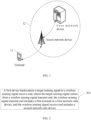
- FIG. 1 is a block diagram of a wireless communication system to which the embodiments of this application are applicable.
- the wireless communication system includes a terminal 11 and a network-side device 12.
- the terminal 11 may be a terminal-side device, such as a mobile phone, a tablet computer (Tablet Personal Computer), a laptop computer (Laptop Computer) or a notebook computer, a personal digital assistant (Personal Digital Assistant, PDA), a palmtop computer, a netbook, an ultra-mobile personal computer (ultra-mobile personal computer, UMPC), a mobile Internet device (Mobile Internet Device, MID), an augmented reality (augmented reality, AR)/virtual reality (virtual reality, VR) device, a robot, a wearable device (Wearable Device), vehicle user equipment (Vehicle User Equipment, VUE), pedestrian user equipment (Pedestrian User Equipment, PUE), a smart home device (a home device with wireless communication function, such as a refrigerator, a television, a washing machine, or a furniture), a game console
- the wearable device includes: a smart watch, a wrist band, smart earphones, smart glasses, smart jewelry (smart bracelet, smart wristband, smart ring, smart necklace, smart anklet, smart ankle bracelet, or the like), smart wristband, smart clothing, game console, and the like. It should be noted that a specific type of the terminal 11 is not limited in the embodiments of this application.
- the network-side device 12 may include an access network device or a core network device, where the access network device may also be referred to as a radio access network device, a radio access network (Radio Access Network, RAN), a radio access network function, or a radio access network unit.
- RAN Radio Access Network
- the access network device may include a base station, a wireless local area network (Wireless Local Area Network, WLAN) access point, a wireless fidelity (Wireless Fidelity, WiFi) node, or the like.
- the base station may be referred to as a NodeB, an evolved NodeB (eNB), an access point, a base transceiver station (Base Transceiver Station, BTS), a radio base station, a radio transceiver, a basic service set (Basic Service Set, BSS), an extended service set (Extended Service Set, ESS), a home NodeB, a home evolved NodeB, a transmission and reception point (Transmitting Receiving Point, TRP), or another appropriate term in the art.
- the base station is not limited to a specific technical term. It should be noted that in the embodiments of this application, the base station in the NR system is merely used as an example, and a specific type of the base station is not limited.
- the core network device may include but is not limited to at least one of the following: a core network node, a core network function, a mobility management entity (Mobility Management Entity, MME), an access and mobility management function (Access and Mobility Management Function, AMF), a session management function (Session Management Function, SMF), a user plane function (User Plane Function, UPF), a policy control function (Policy Control Function, PCF), a policy and charging rules function (Policy and Charging Rules Function, PCRF), an edge application service discovery function (Edge Application Server Discovery Function, EASDF), a unified data management (Unified Data Management, UDM), a unified data repository (Unified Data Repository, UDR), a home subscriber server (Home Subscriber Server, HSS), a centralized network configuration (Centralized network configuration, CNC), a network storage function (Network Repository Function, NRF), a network exposure function (Network Exposure Function, NEF), a local NEF (Local NEF, or L-NE
- the radar and communication systems may be in a same location or even be physically integrated, they transmit two different types of signals in time/frequency domain. They share the same resources through cooperation to minimize mutual interference during working at the same time.
- the corresponding measures include beamforming, cooperative spectrum sharing, primary and secondary spectrum sharing, dynamic coexistence, and so on.
- effective interference cancellation usually imposes strict requirements on mobility of nodes and information exchange between nodes, actually limiting increase of spectrum efficiency. Because interference in the coexistence system is caused by transmitting two independent signals, it is natural to ask whether one transmit signal can be used for communication and radar sensing.
- the radar system usually uses specially designed waveforms, such as short pulses and chirp, which can achieve high power radiation and simplify processing of receivers.
- waveforms are not necessary for radar detection.
- Passive radar or passive sensing takes different radio signals as sensing signals, which is a good example.
- Wireless sensing here may broadly refer to retrieving information from received radio signals, rather than modulating communication data onto the signals on the transmitter.
- dynamic parameters such as reflection delay, angle of arrival (Angle of Arrival, AOA), angle of departure (Angle of Departure, AOD), and Doppler of target signals can be estimated by using a common signal processing method.
- Physical characteristics of the sensing target can be implemented by measuring natural mode signals of devices, objects, and living things. The two sensing manners can be referred to as sensing parameter estimation and pattern recognition.
- wireless sensing refers to more general sensing technologies and applications using radio signals.
- Integrated sensing and communication has the potential to integrate wireless sensing into large-scale mobile networks, which is referred to as perceptive mobile networks (Perceptive Mobile Networks, PMNs) here.
- the PMN may evolve from the current 5G mobile network, and is expected to become a ubiquitous wireless sensing network while providing stable and high-quality mobile communication services. It can be built on the existing mobile network infrastructure without major changes to the network structure and devices. It will release the maximum capacity of the mobile network and avoid spending high infrastructure costs to build a new wide-area wireless sensing network separately. With expansion of coverage, integrated communication and sensing capabilities are expected to implement many new applications.
- Sensing mobile networks can provide communication and wireless sensing services, and may become a ubiquitous wireless sensing solution because of its large broadband coverage and strong infrastructure. The joint and coordinated communication and sensing capabilities will improve the productivity of our society and help to spawn a large number of new applications that cannot be effectively realized by using existing sensor networks.
- Some early work of passive sensing using mobile signals has proved its potential, for example, traffic monitoring, weather forecast, and rainfall remote sensing based on radio signals of the global system for mobile communications (Global System for Mobile Communications, GSM).
- GSM Global System for Mobile Communications
- the wireless sensing signal receive ends can determine sensing measurement quantities and sensing results based on received sensing signals sent by the wireless sensing signal transmit ends, and the wireless sensing signal transmit ends and the wireless sensing signal receive ends include power-consuming radio frequency links, including oscillators, mixers, digital-analog converters, and the like.
- At least part of signals sent by the wireless sensing signal transmit end can be backscattered by a first device with less energy consumption and small size, so as to provide a new sensing path and even new sensing assistance information, thereby improving the sensing performance of the ISAC system.
- the low-power and low-complexity backscatter communications (Backscatter Communications, BSC) technology is a technology that simply relies on passive reflection and modulation of incident radio frequency (Radio Frequency, RF) waves.
- RF radio frequency
- 5G communications technologies, and the big data analysis technologies supported by cloud computing rapid growth of the Internet of things has attracted great attention from the industry and academia.
- One of the main open challenges for the Internet of things is that a large number of Internet of things devices are powered by batteries with limited capacity, resulting in a limited network life cycle.
- the BSC technology has become a promising technology to meet such challenge.
- the conventional radio architecture has a power-consuming radio frequency link, including an oscillator, a mixer and a digital-analog converter, which results in a relatively large device size, thereby greatly limiting a battery life for Internet of things devices.
- the hardware has extremely low power consumption (for example, 10 ⁇ W). This facilitates large-scale deployment in various flexible scenarios and even implantation into the body.
- RFID Radio Frequency Identification
- Passive RFID tags can report IDs to readers for near-field (usually several centimeters to one meter) query.
- RFID devices for logistics and inventory management.
- 6G Internet of things is expected to connect tens of billions of devices, so as to implement more complex tasks with more functions and bring a global impact. This requires that the communication capability and range (tens of meters) between Internet of things nodes far exceed the original RFID, that is, only supporting burst and low-rate transmission within several meters (only pre-written ID sequences of several bytes are transmitted).
- a communication distance of conventional RFID is in the order of m and a communication distance of next-generation BSC is generally expected to reach the order of km.
- the conventional RFID uses binary modulation, with a communication rate being generally not greater than 640 Kbps, and the next-generation BSC can use high-order modulation, with a communication rate reaching up to at least 10 Mbps or even 2 Gbps.
- advanced communication technologies such as small cellular network, full duplex, multi-antenna communication, large-scale access, and wireless power transmission, as well as micro-radios (such as button-sized radios) and low-power electronic device manufacturing have made the foregoing goals come true.
- micro-radios such as button-sized radios
- integration of communication and sensing is able to foster a series of new 6G applications.
- integration of communication and sensing based on low-power communications devices also becomes an important application scenario of 6G.
- wireless sensing based on the radio frequency identification (Radio Frequency Identification, RFID) and backscatter communications (Backscatter Communications) technologies can implement basic sensing functions and also obtain additional sensing target information, which is expected to further enhance the performance of sensing/integrated communication and sensing.
- RFID and backscatter-based sensing and integrated communication and sensing is expected to be widely used in 6G.
- roadside units Roadside Unit, RSU
- RSU roadside Unit
- RFID or backscatter tag tag
- the tag can provide additional assistance information such as a vehicle ID and a current status of the vehicle.
- the RSU By receiving a reflected signal from the tag, the RSU can accurately identify and distinguish different vehicles on the road while implementing high-precision vehicle positioning, speed measurement, and trajectory tracking, thereby expanding the sensing capability.
- key technologies in RFID-based wireless sensing such as waveform design for tag-based integrated communication and sensing, frame structure design, sensing scheme, and algorithm design, are all problems that need to be studied and resolved.
- the embodiments of this application provide a wireless sensing scheme based on a backscattering function of a first device, so that the first device can be applied to wireless sensing.
- a first wireless sensing method provided in an embodiment of this application can be executed by a first device.
- the first device has a backscattering function
- the first device may include devices with the backscattering function (or referred to as backscattering function), such as a radio frequency identification (Radio Frequency Identification, RFID) tag and a backscattering (Backscatter) tag, which are not described one by one herein.
- the first device being a tag is used as an example for description, and the first device may include one tag or a tag array formed by a plurality of tags.
- the first device may also include other devices with the backscattering function, or may even include other sensing components, which is not specifically limited herein.
- the first wireless sensing method may include the following steps.
- Step 201 The first device backscatters a target sensing signal to a wireless sensing signal receive end, where the target sensing signal comes from a wireless sensing signal transmit end, the wireless sensing signal transmit end includes a first terminal or a first network-side device, and the wireless sensing signal receive end includes a second network-side device.
- the first device may have an antenna, and a signal collection range of the antenna is greater than or equal to a first distance between the first device and the wireless sensing signal receive end, and greater than or equal to a second distance between the first device and the wireless sensing signal transmit end, so that the target sensing signal from the wireless sensing signal transmit end can be collected by using the antenna of the first device, and the backscattered target sensing signal can be received by the wireless sensing signal receive end.
- the first device performs processes such as adjusting a matching impedance of the antenna to backscatter a wireless sensing signal collected by the antenna.
- the first device has a backscattering function, that is, the first device is a device with low power consumption and low complexity, and supports backscattering communication.
- the device supporting backscattering communication can send information by modulating and backscattering (hereinafter referred to as "reflection") wireless signals received from the environment, not requiring conventional communication modules such as power-consuming transceivers and amplifiers, thereby implementing extremely low power consumption and low cost communication.
- the device supporting backscattering communication can choose to collect energy of surrounding wireless signals or other energy for its communication, thus implementing even zero-power consumption communication.
- the wireless sensing signal transmit end may be a first network-side device (for example, a base station or a transmission and reception point (Transmit Receive Point, TRP)) or a first terminal
- the wireless sensing signal receive end may be a second network-side device (for example, a base station or a TRP).
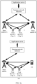
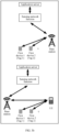
- the wireless sensing signal receive end may be a base station, and the wireless sensing signal transmit end can be a base station or a terminal. That is, a base station A sends a sensing signal, part or all of the signal is backscattered by a tag, and a base station B receives the sensing signal; or user equipment (User Equipment, UE) sends a sensing signal, part or all of the signal is backscattered by a tag, and a base station receives the sensing signal.
- UE User Equipment
- the wireless sensing signal receive end may alternatively be a terminal, or may be a same network-side device or a same terminal as the wireless sensing signal transmit end.
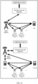
- the wireless sensing signal receive end and the wireless sensing signal transmit end are a same device (base station or terminal), that is, a base station transmits a sensing signal, part or all of the signal is backscattered by a tag, and the base station receives the sensing signal; or UE sends a sensing signal, part or all of the signal is backscattered by a tag, and the UE receives the sensing signal.
- a base station transmits a sensing signal, part or all of the signal is backscattered by a tag
- the base station receives the sensing signal
- UE sends a sensing signal, part or all of the signal is backscattered by a tag, and the UE receives the sensing signal.
- the wireless sensing signal receive end may be UE, and the wireless sensing signal transmit end can be a base station or a terminal. That is, UE A sends a sensing signal, part or all of the signal is backscattered by a tag, and UE B receives the sensing signal; or a base station sends a sensing signal, part or all of the signal is backscattered by a tag, and UE receives the sensing signal.
- This embodiment of this application mainly describes the application scenario shown in FIG. 3a , that is, the base station receives the sensing signal that is sent by the terminal or another base station and at least partially backscattered by the first device, so as to obtain a sensing measurement quantity.
- the method before the backscattering, by a first device, a target sensing signal to a wireless sensing signal receive end, the method further includes:
- the first indication information is used to indicate specified first information that the first device modulates onto the target sensing signal.
- the target sensing signal can be understood as a sensing signal for sensing measurement.
- the first indication information and the target sensing signal may be signals sent by the wireless sensing signal transmit end at different times, for example, the first device obtains the first indication information first, and then determines the first information according to the first indication information. After a time gap (time gap) elapses, the first device modulates the previously determined first information onto a sensing signal and backscatters the sensing signal, and the wireless sensing signal receive end receives the modulated sensing signal.
- That the first device modulates the first information onto the sensing signal can be understood as: the first device performs a process such as adjusting a matching impedance to affect an amplitude, or phase, or frequency of a sensing signal in the environment in which the first device is located, so as to modulate the sensing signal and make the sensing signal carry the first information.
- the first indication information and the target sensing signal may be located in different information fields of a same signal, for example, a header area of a specific signal may carry the first indication information, and other areas of the signal may be considered as a sensing signal for sensing measurement.
- the first device may demodulate a received signal to obtain the first indication information, and according to indication of the first indication information, prepares the first information that needs to be modulated onto the backscattered sensing signal.
- the first device can provide additional first information, such as location information of the first device, information about a target sensing object to which the first device is attached, and the like.
- the first information may be used to provide assistance for the wireless sensing process, and the first information of the first device may even be directly used as a sensing result, thereby improving sensing performance of the wireless sensing process.
- the target sensing signal sent by the wireless sensing signal transmit end may be an unmodulated continuous wave (Continuous Wave, CW) signal, and that the first device modulates the first information onto the target sensing signal includes: the first device modulates the first information onto the CW signal.
- CW Continuous Wave
- the first indication information may indicate which first information the first device needs to modulate onto the backscattered target sensing signal, for example, the first information includes a second measurement quantity collected by the first device, or includes other related information pre-stored in a tag.
- the tag modulates the first information onto the CW signal.
- the first device may modulate the first information onto the backscattered target sensing signal, so as to provide other information than the sensing measurement quantity for the sensing process. This helps improve sensing performance of the sensing system.
- the target sensing signal received by the first device may also be of other signal types, and a manner in which the first device backscatters the target sensing signal and a manner in which the first information is carried in the backscattered target sensing signal can be adaptively adjusted, which is not specifically limited herein.
- the first device may directly backscatter the sensing signal without obtaining the first indication information.
- the sensing signal backscattered by the first device may not carry the first information added by the first device.
- the sensing signal sent by the wireless sensing signal transmit end is a preset sensing signal sequence with known or predetermined signal configuration information, for example, a waveform, a bit sequence, and a frequency range.
- the preset sensing signal sequence is backscattered by the first device to the wireless sensing signal receive end, and the wireless sensing signal receive end can perform target signal processing based on the target sensing signal sequence and the preset sensing signal sequence to obtain a target measurement quantity.
- Target signal processing includes but is not limited to operations such as matched filtering, cross correlation, and sliding correlation, and a result of target signal processing is to obtain a target measurement quantity.
- the sensing signal sent by the wireless sensing signal transmit end may alternatively be at least two sensing signals sent at intervals, which is not specifically limited herein.
- the sensing signal receive end may perform at least one of measurement, demodulation, and other processing on the target sensing signal to obtain the target measurement quantity.
- a target sensing result required for the target sensing requirement information is determined based on the target measurement quantity.
- a node that determines the target sensing result based on the target measurement quantity may be a base station, UE, a core network, or an application server, which is not specifically limited herein.
- the wireless sensing signal receive end may obtain a target sensing result through calculation based on the obtained target measurement quantity, and then directly or indirectly send the target sensing result to an initiator of a sensing service; or the sensing signal receive end may send the target measurement quantity to at least one of another base station, UE, the core network, or the application server, so that the at least one of the another base station, the UE, the core network, or the application server obtains a target sensing result through calculation, and then send it to the initiator of the sensing service.
- adding a tag has the following advantages:
- the target sensing signal may be a sensing signal of a specific sensing service, such as weather monitoring, reconstruction of three-dimensional maps, traffic/crowd sensing, air quality detection such as PM2.5 monitoring, monitoring of pollutants in factories, monitoring of farm animals, or recognition of human actions/postures.
- a specific sensing service such as weather monitoring, reconstruction of three-dimensional maps, traffic/crowd sensing, air quality detection such as PM2.5 monitoring, monitoring of pollutants in factories, monitoring of farm animals, or recognition of human actions/postures.
- An initiator of the sensing service may be a third-party application, a core network (or a network management system or a base station), or UE.
- the sensing method provided in this embodiment of this application may include the following steps:
- At least one of the core network, the application server, the base station, or the UE can determine the target sensing result based on the target measurement quantity.
- step (8) may include the following specific processes:
- step (8) may include the following specific processes:
- step (8) may include the following specific processes:
- a core network function or network element obtains a sensing requirement and/or sensing signal related configuration from an AMF of the core network; or the AMF receives a sensing requirement or sensing signal related configuration information sent by a network management system and forwards it to the sensing network element; or the AMF receives a sensing requirement or sensing signal related configuration information sent by a base station initiating the sensing service and forwards it to the sensing network element (certainly, a sensing requirement or sensing signal related configuration information of the wireless sensing signal transmit end (the base station A or UE) may be directly sent to the wireless sensing signal receive end (the base station B), without being sent to the core network.) After the wireless sensing signal receive end obtains the target measurement quantity, a node
- the initiator of the sensing service may obtain the target sensing result in the following manner:
- the initiator of the sensing service may obtain the target sensing result in the following manner:
- the initiator of the sensing service may obtain the target sensing result in the following manner:
- the core network may not participate in the whole sensing process, for example, the base station or UE initiates the sensing service, and the conversion from the target measurement quantity to the target sensing result is completed by the UE or the base station.
- the sensing service is initiated by UE (UE that sends a target sensing signal, UE that is served by a base station that sends a target sensing signal, or other UEs, which is collectively referred to as a UE initiating the sensing service in this embodiment for ease of description), a difference between the sensing method provided in this embodiment of this application and the specific embodiment 1 is as follows:
- the initiator of the sensing service may obtain the target sensing result in the following manner:
- the initiator of the sensing service may obtain the target sensing result in the following manner: the base station B converts the target measurement quantity into a target sensing result, and sends the target sensing result to the core network (the AMF or the sensing network element).
- the core network (the AMF or the sensing network element) sends the sensing result to the UE initiating the sensing service (via NAS signaling); or the core network (the AMF or the sensing network element) sends the sensing result to an associated base station of the UE initiating the sensing service, and the associated base station sends the sensing result to the UE initiating the sensing service.
- the initiator of the sensing service may obtain the target sensing result in the following manner:
- the core network may not participate in the whole sensing process, for example, the UE initiates the sensing service, and the conversion from the target measurement quantity to the target sensing result is completed by the UE or the base station.
- the foregoing process of determining the target sensing result (for example, three-dimensional map) based on the target measurement quantity (for example, angle information or signal received power information) can be completed by the UE or the base station A or the base station B, or the core network, or the application server.
- Related information of the base station A or UE such as antenna position, synchronization information (SFN start time), AI related information (for example, AI training data), and the like can also be sent to a node that completes conversion of the target measurement quantity to the target sensing result, so as to assist in completing the conversion process.
- a charging function is completed in the core network or application server.
- the core network function or network element (such as the sensing network function/sensing network element) is collectively referred to as a second device in the following embodiments.
- the second device may be a sensing network function/sensing network element in the core network or a sensing network function/sensing network element in the access network, which is not specifically limited herein.
- the second device satisfies at least one of the following characteristics:
- At least one of the a-priori information or the capability information of the tag is reported by the target tag to the network-side device such as the base station or SNF, for example, the first information is read and reported by a reader (such as a base station accessed by the tag) of the tag.
- the first information includes at least one of the following: an identifier of the first device, status indication information about the first device participating in sensing (which may be a participation sensing flag bit (indicating whether it is allowed or agreed to participate in sensing currently)), a sensing time period of the first device (indicating a start and end time/duration of participation in sensing), a sensing service occupancy flag bit (or status indication information with a same meaning, indicating whether sensing service is currently being conducted), an incident angle and reflection angle range of the first device (the incident angle range is an incident angle range of the sensing signal that enables the tag to work normally; and the reflection angle range is a reflection angle range of a reflected signal of the tag), the number of first devices in an associated area, location information of the first device (two-dimensional or three-dimensional, Cartesian coordinates or polar coordinates including a tag and a reference system origin), a sensing distance of the first device, a working bandwidth of the first device, a working frequency of channels of the first device (that is, subcar
- the SNF is capable of determining an association between the base station and the tag in the sensing area based on location information of the base station mastered by the SNF or obtained by the SNF from the AMF and first information stored in tags associated with the target tag area.
- the association criterion is to ensure that a signal-to-noise ratio of the sensing signal reflected by the tag and received by the base station meets requirements (such as meeting a QoS requirement and meeting a sensing condition corresponding to the sensing requirement information), and the sensing distance is greater than or equal to a distance between the base station and the tag.
- the first device participating in sensing needs to access the wireless sensing signal transmit end and the wireless sensing signal receive end, and a sensing signal strength between the first device and the wireless sensing signal transmit end and a signal strength between the first device and the wireless sensing signal receive end meet a sensing condition corresponding to the sensing requirement information.
- the SNF or the core network AMF can determine a tag participating in sensing, a base station A sending the target sensing signal, and a base station B receiving the target sensing signal based on the sensing requirement and pre-obtained capability information and location information of the tags and base stations.
- a tag in a target sensing area corresponding to the sensing requirement is determined as a tag participating in sensing, and a base station A and a base station B are determined based on base stations accessed by the tag participating in sensing and based on capability information and/or location information of the base stations accessed by the tag participating in sensing.
- the first device is determined first, and then the wireless sensing signal transmit end and the wireless sensing signal receive end are determined based on the base stations accessed by the first device.
- the base station A and the base station B are determined from base stations that meet a sensing condition corresponding to the sensing requirement, and a tag accessing the base station A and the base station B is determined as a tag participating in sensing.
- the wireless sensing signal transmit end and the wireless sensing signal receive end are determined first, and then the first device is determined based on the base stations accessed by the tag.
- the SNF can schedule an associated base station of the target tag (the associated base station of the tag may include at least one of a serving base station of the tag and an associated base station in an area where the tag is located) to serve as a reader (reader) of the tag.
- the base station can adjust a beam, read information from a storage area of a tag, or read polling information from storage areas of a plurality of tags in an area. After reading related information, the base station can report the information to the SNF, so as to update a-priori information stored and managed by the SNF or to use it as necessary or assistance information for the sensing service.
- the SNF can schedule an associated base station of the target tag to act as a writer (writer) of the tag.
- the base station can adjust a beam, write information into a storage area of a tag, or write polling information into storage areas of a plurality of tags in an area.
- the SNF can schedule an associated base station of the target tag to perform tag selection.
- a tag selection operation of the base station in the sensing process can be indicated.
- the base station can adjust a beam and select a tag that meets a sensing condition corresponding to the sensing requirement, so that the tag that meets the sensing requirement and the sensing condition enters a corresponding active state while other tags that do not meet the sensing requirement and the sensing condition are in an inactive state.
- the SNF can schedule an associated base station of the target tag to perform inventory for the tag.
- the base station can adjust a beam, circularly scan all tags that meet a selection condition, and the tags return their EPC codes (EPC codes: codes used to identify tag attached objects) respectively.
- EPC codes codes used to identify tag attached objects
- the SNF can schedule an associated base station of the target tag to provide power for the target tag.
- the second device is located at the core network or the base station side. If the second device is located at the base station side, all processes of the sensing service can be completed at the radio access network (Radio Access Network, RAN) side (for example, for a case that the sensing service is triggered for the base station or the UE triggers the sensing service).
- radio access network Radio Access Network, RAN
- the second device may be a separate function/physical entity, or deployed in a general server of the core network as one of the core network functions, or deployed at the base station side as one of the functions of the base station.
- the second device may directly exchange a sensing request (including the sensing requirement information) and a sensing result with an application server (for example, an application server of the operator); or the second device exchanges a sensing request and a sensing result with the AMF, and the AMF can directly or indirectly exchange a sensing request and a sensing result with the application server (such as a third-party application server) (through a gateway mobile location center (Gateway Mobile Location Center, GMLC) and a network exposure function (Network Exposure Function, NEF)).
- GMLC Gateway Mobile Location Center
- NEF Network Exposure Function
- a plurality of sensing network elements may correspond to one AMF, or a single sensing network element may be connected to a plurality of AMFs.
- the AMF when obtaining sensing requirement information, the AMF can determine, based on the sensing requirement information, at least one of the corresponding plurality of sensing network elements as a second device participating in a sensing process corresponding to the sensing requirement information.
- Factors to be considered for determining a sensing network element participating in the sensing process by the AMF include at least one of the following: request QoS (such as sensing accuracy, response time, and sensing QoS level), access type (3GPP access/non-3GPP access), access network AN type (that is, 5G NR or eLTE) and serving AN node (that is, gNodeB or NG-eNodeB) of the target UE, RAN configuration information, capability of the sensing network element, load of the sensing network element, location of the sensing network element, indication of single event reporting or multi-event reporting, event reporting duration, network slice information, and the like.
- request QoS such as sensing accuracy, response time, and sensing QoS level
- access type 3GPP access/non-3GPP access
- access network AN type that is, 5G NR or eLTE
- serving AN node that is, gNodeB or NG-eNodeB
- the sensing requirement is a three-dimensional map of the sensing target area
- information about a base station that may require interactive information is obtained through interaction with other network elements/functions in the core network.
- the core network or the sensing network element
- application server or other nodes (such as the AMF) can complete the supervision procedure.
- a manner of determining the target UE by the core network function or network element may include at least one of the following:
- a manner of determining an associated base station by the core network function or network element may include at least one of the following:
- a manner of determining a target tag by the core network function or network element may include at least one of the following:
- sensing requirement there may be an association between the sensing requirement and the sensing signal related configuration corresponding to the sensing requirement, so that a node obtaining the sensing requirement information can determine the sensing signal related configuration information based on the association between the sensing requirement and the sensing signal related configuration.
- corresponding sensing signal related configuration information may alternatively be determined based on the sensing requirement information in other manners (for example, a bandwidth of the sensing signal is determined based on a sensing resolution requirement), and a node that determines the corresponding sensing signal related configuration information based on the sensing requirement information may be at least one of the base station, the core network, the UE, and the second device.
- Manner 1 The base station A (corresponding to a sensing signal transmission manner in which the base station A sends a sensing signal) or UE (corresponding to a sensing signal transmission manner in which the UE sends a sensing signal) reports its own sensing capability (a capability related to sending of sensing signals, such as a maximum bandwidth for sending sensing signals and a maximum transmit power of sensing signals) to the core network (the AMF or the sensing network element); and/or, the base station B reports its own sensing capability (a capability related to receiving of sensing signals, such as a maximum bandwidth for receiving sensing signals and a supported measurement quantity of sensing signals) to the core network (the AMF or the sensing network element); and/or, the base station A, the UE, or the base station B queries a sensing capability of a tag participating in sensing (a capability related to receiving and backscattering of sensing signals, such as a working bandwidth and frequency point and a maximum read-write frequency supported, where such information is stored in the tag) and then reports the
- Manner 2 The base station A or the base station B (corresponding to a sensing signal transmission manner in which the base station A sends a sensing signal) or the UE and/or base station B (corresponding to a sensing signal transmission manner in which the UE sends a sensing signal) determines the sensing signal related configuration information based on the sensing requirement information.
- Manner 3 The core network determines part of the sensing signal related configuration information, and the base station A and/or base station B (corresponding to a sensing signal transmission manner in which the base station A sends a sensing signal) or the UE and/or base station B (corresponding to a sensing signal transmission manner in which the UE sends a sensing signal) determines another part of the sensing signal related configuration information.
- the core network recommends the sensing signal related configuration information to the base station A and/or base station B (corresponding to a sensing signal transmission manner in which the base station A sends a sensing signal) or to the UE and/or base station B (corresponding to a sensing signal transmission manner in which the UE sends a sensing signal), the base station A and/or base station B or the UE and/or base station B finally determines the sensing signal related configuration information.
- Manner 5 The base station A and/or base station B (corresponding to a sensing signal transmission manner in which the base station A sends a sensing signal) or the UE and/or base station B (corresponding to a sensing signal transmission manner in which the UE sends a sensing signal) recommends the sensing signal related configuration information to the core network based on the sensing requirement, and the core network finally determines the sensing signal related configuration information.
- the sensing signal related configuration information includes at least one of the following:
- the target measurement quantity includes: a first measurement quantity, where the first measurement quantity is a measurement quantity related to the first device and includes at least one of the following: a received signal strength indicator (Received Signal Strength Indicator, RSSI) and/or a received power of a reflected signal backscattered by the first device, a phase of the reflected signal, time stamp information of the reflected signal (time information inserted by a tag or tags in a tag array when signals are transmitted), a backscattering path channel matrix H of the first device, backscattering path channel state information CSI of the first device, a multipath number parameter for a backscattering path multipath channel of the first device (including the quantity of multipath, power, delay, and angle information of each path, and the like), a Doppler frequency and Doppler spread of the reflected signal, an angle of departure of the reflected signal (that is, an angle of departure of a transmitted signal of the tag/tag array), an arrival angle of the reflected signal (that is, an, an
- the target measurement quantity may alternatively include a second measurement quantity, and the second measurement quantity may include at least one of the following:
- the characteristic information of the target object may be information that can reflect an attribute or a state of the target object, and may be at least one of the following : position of the target object, speed of the target object, acceleration of the target object, material of the target object, shape of the target object, category of the target object, and radar cross section (Radar Cross Section, RCS) of the target object.
- the related information of the target event is information related to the target event, that is, information that can be detected/sensed when the target event occurs, and may be at least one of the following: fall detection, intrusion detection, action recognition, respiratory monitoring, heart rate monitoring, and the like.
- the related information of the target environment may be at least one of the following: humidity, brightness, temperature and humidity, atmospheric pressure, air quality, weather conditions, topography, building/vegetation distribution, population statistics, crowd density, vehicle density, and the like.
- the first device may also have an information collection function, for example, the first device also includes a sensor, so that the first device can be further configured to collect the second measurement quantity.
- the first device further has an information collection function
- the method further includes: collecting, by the first device, a second measurement quantity corresponding to a sensing target, where the first information includes the second measurement quantity.
- the sensing target may be a sensing target in the wireless sensing method provided in this embodiment of this application.
- the sensing requirement information is a position of the sensing target object
- the sensing target is a target object
- the second measurement quantity corresponding to the sensing target may be orientation information and location information of the target object collected by the first device by using a position sensor.
- the information collection capability of the first device can be used to collect a sensing measurement quantity, and the collected sensing measurement quantity can be modulated onto the target sensing signal backscattered by the first device, so that the wireless sensing signal receive end can obtain the second measurement quantity based on the received target sensing signal.
- the first device can be used to provide an additional measurement quantity for wireless sensing, and a manner of transmitting a measurement quantity via signaling features lower power consumption and fewer signaling overheads compared to a device-based (device-based) sensing mode.
- the target measurement quantity is a measurement quantity for each antenna or a measurement quantity for each sensing resource.
- the target measurement quantity is a measurement quantity for each antenna (port) at the sensing signal transmit end or sensing signal receive end, or the target measurement quantity is a measurement quantity of each sensing resource, such as a measurement quantity of each resource block (Resource Block, RB), subcarrier, or RB group.
- the related information stored in the tag itself can be used as primary/assistance information for sensing and can be transmitted during the sensing process to a function or entity that implements conversion from the target measurement quantity to the target sensing result, so that the function or entity that implements conversion from the target measurement quantity to the target sensing result can determine a target sensing result based on the related information stored in the tag and/or the sensing measurement quantity obtained through measurement,
- the related information stored in the tag can be modulated onto a received CW signal, and the tag backscatters the modulated CW signal to directly or indirectly transmit the related information to a node (such as the core network (or the sensing network element), the application server, the base station, or the UE) that determines the target sensing result based on the target measurement quantity.
- a node such as the core network (or the sensing network element), the application server, the base station, or the UE
- the core network or the SNF can also schedule the base station or the UE to read the related information pre-stored in the first device, for example, sending second indication information to the base station or the UE.
- the second indication information is used to indicate the base station or UE to read the related information pre-stored in the first device.
- a process of obtaining by the UE B the related information pre-stored in the tag is as follows:
- the core network or the SNF After determining a tag-based sensing mode according to the sensing requirement, the core network or the SNF further needs to determine whether an operation such as selection, inventory, and access (information read/write) needs to be performed on a tag participating in the sensing;
- the base station B may demodulate the target sensing signal to obtain the first information.
- the base station B may forward the obtained first information, the measured target measurement quantity, and other information to the core network, the UE, or other base stations; or the base station B may determine the target sensing result based on the first information, the measured target measurement quantity, and other information, and forwards the target sensing result to the initiator of the sensing service corresponding to the target perception requirement information through at least one of the core network, the UE, and other base stations.
- the process is the same as that in the foregoing embodiment in which at least one of the core network, the application server, the base station, or the UE determines the target sensing result based on the target measurement quantity, and the transmission manner of the target measurement quantity is the same, which is not repeated herein.
- the target measurement quantity may include:
- the target measurement quantity includes the demodulated information backscattered by the tag (that is, the first information modulated by the tag onto the target sensing signal, such as a tag ID and position coordinate information of the tag); or may be the demodulated information backscattered by the tag plus at least one of a tag-based wireless sensing measurement quantity (tag-based measurement quantity) and a tag-free wireless sensing measurement quantity (tag-free measurement quantity).
- the tag-based measurement quantity is a measurement quantity obtained after the signal is processed by the tag, for example, an RSSI/receive power and phase of a plurality of reflected signals of the sensing signal by the tag array, and the reflected signals are modulated by the tag and can be distinguished by different tag IDs; and the tag-free measurement quantity is a measurement quantity that can be obtained without assistance of the tag, for example, the antenna array of the base station obtains an azimuth angle of the tag relative to the base station based on a phase of a reflected signal from the sensing target tag, without any processing on an incident sensing signal, where the phase of the reflected signal of the tag is a tag-free measurement quantity.
- the target sensing result may include a sensing result obtained based on the demodulated information backscattered by the tag (that is, the first information carried in the backscattered target sensing signal), or the demodulated information backscattered by the tag is directly used as the sensing result.
- the target sensing result may also include a sensing result obtained based on at least one of the two types: the tag-based measurement quantity and the tag-free measurement quantity, or the target sensing result may be a comprehensive sensing result obtained from the foregoing three types of sensing results.
- some a-priori information of the tag may be stored in the core network (or the sensing network element), or the base station, or the tag participating in sensing, and needs to be called or transferred during the sensing process.
- the first information may include at least one of the following: a tag ID list, status indication information for participation in sensing (which may be a flag bit for participation in sensing (indicating whether it is allowed or agreed to participate in sensing currently)), a sensing time period (indicating a start and end time/duration of participation in sensing), sensing service occupancy flag bit (or status indication information with a same meaning, indicating whether sensing service is currently being conducted), an incident angle and reflection angle range of the tag (the incident angle range is an incident angle range of the sensing signal that enables the tag to work normally; and the reflection angle range is a reflection angle range of a reflected signal of the tag), the number of tags in an associated area, and a tag location information list (two-dimensional or three-dimensional, Cartesian coordinates or polar coordinates including a tag and a reference system origin), a tag sensing distance list, a tag communication bandwidth list, a working frequency (that is, subcarrier frequency within bandwidth) list of channels of the tag, a tag modulation mode list, a
- the related information of the tag is updated (for example, the tag moves (position coordinates change), a tag is added in the network, a tag is canceled (becomes invalid), or the like), communication between the core network (or sensing network element), the base station (base station, BS), and the tag can also be implemented through the foregoing process, current information of the tag can be obtained based on a communication result, and the a-priori information of the tag in the core network (or the sensing network element) can be updated accordingly.
- the method further includes: the first device cooperates with the wireless sensing signal transmit end and the wireless sensing signal receive end to perform reference measurement, where the reference measurement is used for obtaining a reference measurement quantity or a reference measurement result, and the target sensing result is determined based on the target measurement quantity and the reference measurement quantity or the reference measurement result.
- reference measurement is needed.
- the final sensing result needs to be determined based on a direct sensing result obtained after execution of the sensing service and a sensing result of the reference measurement.
- a direct sensing result obtained after execution of the sensing service and a sensing result of the reference measurement.
- reference measurement needs to be performed when an object is not in the area, and a corresponding measurement quantity is an RSSI or phase of the reflected signal of the tags. After the object enters the tag area, measurement is performed again to complete the sensing process.
- weather such as humidity and rainfall
- reference measurement needs to be performed in a specific humidity or a no-rainfall period.
- a sensing initiator of reference measurement is not necessarily a third-party application, and may alternatively be the core network (or the sensing network element), or a base station, or UE, and that the measurement environment may be different.
- the foregoing reference measurement quantity or reference measurement result may be stored in the core network (or the sensing network element) or the tag participating in sensing, or may be stored in the base station, so that the node that completes conversion from the target measurement quantity to the target measurement result can obtain the reference measurement quantity or reference measurement result.
- reference measurement can be executed first, and then the sensing service can be executed, so as to correct an error of the target measurement quantity or the target measurement result based on the reference measurement quantity or the reference measurement result; or the sensing service may be executed first, reference measurement is then executed, and finally the target sensing result is determined based on the target measurement quantity as well as the reference measurement quantity or the reference measurement result.
- the sensing signal in the foregoing process can be sent by a plurality of base stations or UEs, and/or the sensing signal receive end may also be a plurality of base stations, and/or the number of tags participating in sensing may also be one or more.
- the core network needs to determine a base station set and UE set that send sensing signals, a tag set that participate in sensing, and a UE set that receive sensing signals, sends sensing signal related configuration information of the plurality of base stations or UEs and related information of tags participating in sensing to the corresponding plurality of base stations or UEs, and sends measurement quantities related to sensing signals that need to be measured by the receive base stations and the related information of tags participating in sensing to the corresponding receive base stations.
- a plurality of transmit base stations need to exchange sensing signal related configuration information with UEs (for example, the base station or UE acting as a coordinator sends the sensing signal related configuration information and the related information of tags participating in sensing to other transmit base stations and UEs, and sends sensing signal related measurement quantities and the related information of tags participating in sensing to other receive base stations).
- UEs for example, the base station or UE acting as a coordinator sends the sensing signal related configuration information and the related information of tags participating in sensing to other transmit base stations and UEs, and sends sensing signal related measurement quantities and the related information of tags participating in sensing to other receive base stations.
- Message exchange between the core network function or network element such as the sensing network function/sensing network element
- the UE in the foregoing procedure may be performed through the base station, or the message may be transparent to the base station, such as NAS signaling.
- the base station in the foregoing procedure may be a TRP, for example, the base station A is a TRP A and the base station B is a TRP B.
- the TRP A and TRP B may belong to a same base station or different base stations.
- the method before the backscattering, by a first device, a target sensing signal to a wireless sensing signal receive end, the method further includes:
- the first device obtains the second sensing request message, which may be a second sensing request message received by the first device from the base station/core network, and the first device outputs the second sensing response message, which can be understood as: the first device generates the second sensing response message for the base station or other access devices to read, or modulates the second sensing response message onto a received wireless signal for the base station or other access equipment to receive.
- the base station/core network initially selects a tag participating in sensing according to the sensing requirement information, and sends a second sensing request message to the selected tag, so as to read status indication information for participation in the sensing process. If it indicates that the tag agrees to participate in the sensing process, it can be determined as a first device participating in the sensing process, and if it indicates that the tag does not agree to participate in the sensing process, another tag may be reselected.
- the first device may receive the second sensing request message from the base station/core network and feeds back the second sensing response message to the base station/core network to inform the base station/core network whether the first device agrees to participate in the sensing process or whether it agrees to provide the first information.
- the tag in the process of reflecting the sensing signal, can choose to agree or refuse to participate in the sensing process and/or provide related a-priori information stored in the tag.
- the first device can alternatively use other manners to choose to agree or refuse to participate in the sensing process and/or provide related a-priori information stored in the tag.
- the tag uses the status indication information for participation in sensing to indicate agreeing or refusing to participate in sensing and/or to provide the related a-priori information stored in the tag; or
- the UE can also choose to agree or refuse to participate in the sensing process by using the following method:
- the first device backscatters the target sensing signal to the wireless sensing signal receive end, where the target sensing signal comes from the wireless sensing signal transmit end, the wireless sensing signal transmit end includes the first terminal or the first network-side device, and the wireless sensing signal receive end includes the second network-side device.
- the target sensing signal sent by the wireless sensing signal transmit end is at least partially backscattered to the wireless sensing signal receive end by using the backscattering function of the first device.
- An additional sensing path can be provided for wireless sensing through the backscattering function of the first device.
- the first device with the backscattering function features a small size and low power consumption because of no power-consuming radio frequency link, and can be more conveniently arranged in an ISAC system than the wireless sensing signal transmit end and receive end, thereby improving sensing performance of the ISAC system.
- FIG. 4 is a flowchart of a second wireless sensing method according to an embodiment of this application.
- the wireless sensing method executed by the wireless sensing signal receive end may include the following steps.
- Step 401 The wireless sensing signal receive end obtains second information, where the second information includes sensing requirement information and/or target sensing signal related configuration information corresponding to the sensing requirement information.
- Step 402 The wireless sensing signal receive end performs, according to the target sensing signal related configuration information, measurement on a target sensing signal sent by a wireless sensing signal transmit end and at least partially backscattered by the first device, so as to obtain a target measurement quantity, where the wireless sensing signal transmit end includes a first terminal or a first network-side device (for example, the UE or the base station A shown in FIG. 3a ).
- the wireless sensing signal transmit end includes a first terminal or a first network-side device (for example, the UE or the base station A shown in FIG. 3a ).
- Step 403 The wireless sensing signal receive end determines a target sensing result based on the target measurement quantity, or sends the target measurement quantity.
- the process of obtaining the sensing requirement information and/or sensing signal related configuration information, the transmission process of the target sensing signal, and the conversion process from the target measurement quantity to the target sensing result in this embodiment of this application are the same as those in the method embodiment shown in FIG. 2 , which are not specifically limited herein.
- the performing, by the wireless sensing signal receive end, according to the target sensing signal related configuration information, measurement on a target sensing signal sent by a wireless sensing signal transmit end and at least partially backscattered by the first device, so as to obtain a target measurement quantity includes:
- the sensing signal sent by the wireless sensing signal transmit end is a preset sensing signal sequence with at least one of signal parameters such as waveform, bit sequence, and frequency range being determined in advance.
- the first device may directly backscatter, to the wireless sensing signal receive end, a preset sensing signal sequence sent by the wireless sensing signal transmit end, so that the wireless sensing signal receive end can perform at least one of target signal processing such as matched filtering, cross correlation, and sliding correlation on the received target sensing signal sequence and the preset sensing signal sequence, so as to determine a target measurement quantity based on a result of target signal processing.
- the sensing signal sent by the wireless sensing signal transmit end and at least partially backscattered by the first device can be a conventional sensing signal.
- the wireless sensing signal receive end can perform measurement on the received sensing signal to obtain a target measurement quantity such as a receiving frequency, a receiving time, or a receive power, and determines a target sensing result based on the target measurement quantity.
- the backscattering function of the first device can be used to expand a transmission path of the sensing signal, thereby improving a sensing range and accuracy of the wireless sensing system.
- the wireless sensing signal transmit end may send first indication information and the target sensing signal, where the first indication information is used to indicate the first device to modulate first information onto the target sensing signal, and correspondingly, the wireless sensing signal receive end can demodulate the received target sensing signal to obtain the first information carried by the target sensing signal, that is, the target measurement quantity may include the first information.
- the wireless sensing signal receive end may demodulate the target sensing signal to obtain the first information pre-stored by the first device and modulated onto the sensing signal, so that the wireless sensing signal receive end can use the first information as one of the target measurement quantities, that is, using the first information as one of the bases for determining the target sensing result (other bases may be other sensing measurement quantities obtained by performing measurement on the target sensing signal and other information obtained in advance, such as antenna information and capability information of the wireless sensing signal transmit end), or directly using the first information as the target sensing result, which can improve comprehensiveness of sensing measurement quantities in the wireless sensing method, thereby improving sensing performance of the wireless sensing system.
- the wireless sensing signal receive end can alternatively directly perform, according to the sensing signal related configuration information, measurement on at least part of the target sensing signal backscattered by the first device to obtain the target measurement quantity, which is not specifically limited herein.
- the second wireless sensing method before the performing, by the wireless sensing signal receive end, according to the target sensing signal related configuration information, measurement on a target sensing signal sent by a wireless sensing signal transmit end and at least partially backscattered by a first device, so as to obtain a target measurement quantity, the second wireless sensing method further includes: sending, by the wireless sensing signal receive end, the second information to the wireless sensing signal transmit end.
- the second information obtained by the wireless sensing signal transmit end may be forwarded by the wireless sensing signal receive end.
- the base station B receives the sensing requirement information from the core network or (the sensing network element) and sends the sensing requirement information and/or the wireless sensing signal related configuration information corresponding to the sensing requirement information to the UE.
- the wireless sensing signal transmit end can alternatively forward the second information to the wireless sensing signal receive end.
- the target measurement quantity includes:
- the target sensing signal related configuration information includes at least one of the following: a waveform, a subcarrier spacing, a guard period, a bandwidth, a burst (burst) duration, a time domain interval, a signal transmit power, a signal format, a signal direction, a time resource, a frequency resource, a quasi-co-location QCL relation, identification information of the first device, information related to a target sensing signal configuration of the first device, an initial phase of the target sensing signal, antenna information of the first device, antenna information of the wireless sensing signal transmit end, time stamp information of the target sensing signal sent by each antenna, a time interval for sending signals between different antennas, an amplitude modulation capability of the first device, a phase modulation capability of the first device, a frequency modulation capability of the first device, an encryption algorithm type of the first device, a coding rate corresponding to a channel coding type of the first device, a signal modulation mode related to the first device, a data coding mode related to the first
- the target measurement quantity includes at least one of the following: a first measurement quantity, where the first measurement quantity is a measurement quantity related to the first device and includes at least one of the following: a received signal strength indicator RSSI and/or a received power of a reflected signal backscattered by the first device, a phase of the reflected signal, time stamp information of the reflected signal, a backscattering path channel matrix of the first device, backscattering path channel state information of the first device, a multipath number parameter for a backscattering path multipath channel of the first device, a Doppler frequency and Doppler spread of the reflected signal, an angle of departure of the reflected signal, an arrival angle of the reflected signal, a phase difference between the first devices, a delay difference between the first devices, a phase difference between antennas of the first device, a delay difference between the antennas of the first device, and the identification information of the first device.
- the second wireless sensing method further includes:
- This implementation is similar to the method embodiment shown in FIG. 2 , and the SNF may alternatively schedule the base station to read the related information pre-stored in the first device, which is not specifically limited herein.
- the second wireless sensing method further includes: sending, by the wireless sensing signal receive end, a first sensing response message in response to reception of the sensing requirement information or the first sensing request message, where the first sensing response message indicates that the wireless sensing signal receive end agrees to participate in a sensing process corresponding to the sensing requirement information or the first sensing request message.
- This implementation is similar to the method embodiment shown in FIG. 2 in which the base station chooses to agree or refuse to participate in the sensing process, which is not described in detail herein.
- the second wireless sensing method before the performing, by the wireless sensing signal receive end, according to the sensing signal related configuration information, measurement on a target sensing signal sent by a wireless sensing signal transmit end and at least partially backscattered by a first device, so as to obtain a target measurement quantity, the second wireless sensing method further includes:
- This implementation is similar to the reference sensing process in the method embodiment shown in FIG. 2 , which is not described in detail herein.
- the second wireless sensing method provided in this embodiment of this application corresponds to the method embodiment shown in FIG. 2 , with similar beneficial effects achieved. To avoid repetition, details are not repeated herein.
- FIG. 5 is a flowchart of a third wireless sensing method according to an embodiment of this application.
- a difference between the method embodiment shown in FIG. 5 and the method embodiment shown in FIG. 2 lies in that an execution subject of the method embodiment shown in FIG. 5 is a second device, and an execution subject of the method embodiment shown in FIG. 2 is a first device.
- the wireless sensing method executed by the second device may include the following steps.
- Step 501 The second device obtains sensing requirement information.
- Step 502 The second device sends second information to at least one of a wireless sensing signal transmit end and a wireless sensing signal receive end, where the second information includes the sensing requirement information and/or target sensing signal related configuration information corresponding to the sensing requirement information, and the wireless sensing signal transmit end includes a first network-side device or a first terminal, and the wireless sensing signal receive end includes a second network-side device.
- Step 503 The second device obtains at least one of a target measurement quantity and a target sensing result, where the target measurement quantity is a measurement quantity obtained by the wireless sensing signal receive end through measurement on a target sensing signal that is transmitted by the wireless sensing signal transmit end and at least partially backscattered by a first device, and the target sensing result is determined based on the target measurement quantity.
- the target measurement quantity is a measurement quantity obtained by the wireless sensing signal receive end through measurement on a target sensing signal that is transmitted by the wireless sensing signal transmit end and at least partially backscattered by a first device, and the target sensing result is determined based on the target measurement quantity.
- the process of obtaining the sensing requirement information and/or sensing signal related configuration information, the transmission process of the target sensing signal, and the conversion process from the target measurement quantity to the target sensing result in this embodiment of this application are the same as those in the method embodiment shown in FIG. 2 , which are not specifically limited herein.
- the second device includes at least one of the following:
- the third wireless sensing method further includes: determining, by the second device, at least one of the wireless sensing signal transmit end, the wireless sensing signal receive end, and the first device based on the sensing requirement information.
- This implementation is similar to the process of determining at least one of the associated base station, the associated UE, and the tag participating in sensing by the core network function or network element (such as the sensing network function/sensing network element) based on the sensing requirement in the method embodiment shown in FIG. 2 , which is not repeated herein.
- the determining, by the second device, the wireless sensing signal transmit end, the wireless sensing signal receive end, and the first device based on the sensing requirement information includes:
- This implementation is similar to the method embodiment shown in FIG. 2 in the process in which the base station and/or the UE reports respective capability information, and/or the base station reads and reports the related information stored in the tag, so that the core network or the sensing network element can select the first device participating in the sensing process, the wireless sensing signal transmit end, and the wireless sensing signal receive based on the capability information of the base station and/or the UE and/or the tag, which is not repeated herein.
- terminals in the wireless sensing signal transmit end and the wireless sensing signal receive end meet at least one of the following conditions:
- the target measurement quantity includes:
- the obtaining, by the second device, at least one of a target measurement quantity and a target sensing result includes:
- the second device obtains the first information in the following manner:
- the second device may obtain the first information of the first device in the following manner: a serving base station or an associated base station of the tag reads an EPC code or tagID of the selected tag participating in the sensing process, and determines a-priori information of the selected target tag from a-priori information of a large number of tags stored in advance, or reads the a-priori information of the selected tag through the serving base station or the associated base station of the tag.
- This embodiment of this application is similar to the method embodiment shown in FIG. 2 , in which the core network, the base station, or the UE determines the target sensing result based on the target measurement quantity, or based on the target measurement quantity and the first information, which is not described in detail herein.
- the third wireless sensing method further includes at least one of the following:
- the associated network-side device of the first device can be understood as: the first device is located within coverage of the associated network-side device (such as a base station) of the first device, and intensity of the sensing signal transmitted between the two meets the sensing condition corresponding to the sensing requirement.
- the third wireless sensing method further includes:
- the obtaining, by the second device, a reference measurement quantity or a reference measurement result includes: obtaining, by the second device, a pre-stored reference measurement quantity or reference measurement result, or receiving, by the second device, a reference measurement quantity or reference measurement result from at least one of the following: the wireless sensing signal transmit end, the wireless sensing signal receive end, the first device, a network-side device accessed by the wireless sensing signal transmit end, a network-side device or terminal accessed by the first device, and a target core network element.
- the second device obtains the sensing requirement information includes: obtaining, by the second device, sensing requirement information sent or forwarded by the target core network element, where the target core network element includes an application server, an access and mobility management function AMF network element, or a network management system.
- the third wireless sensing method before the sending, by the second device, second information to at least one of a wireless sensing signal transmit end and a wireless sensing signal receive end, the third wireless sensing method further includes:
- the process that the second device sends the first recommendation information to the wireless sensing signal transmit end based on the sensing requirement information and receives the sensing signal related configuration information from the wireless sensing signal transmit end is similar to the process in the method embodiment shown in FIG. 2 that the core network recommends the sensing signal related configuration information to the base station A (corresponding to a sensing signal transmission manner in which the base station A sends a sensing signal) or the UE (corresponding to a sensing signal transmission manner in which the UE sends a sensing signal) based on the sensing requirement, and the base station A or the UE finally determines the sensing signal related configuration information, which is not specifically limited herein.
- the process that the second device receives the second recommendation information from the wireless sensing signal transmit end and determines the sensing signal related configuration information based on the second recommendation information and the sensing requirement information is similar to the process in the method embodiment shown in FIG. 2 that the base station A (corresponding to a sensing signal transmission manner in which the base station A sends a sensing signal) or the UE (corresponding to a sensing signal transmission manner in which the UE sends a sensing signal) recommends the sensing signal related configuration information to the core network based on the sensing requirement, and the core network finally determines the sensing signal related configuration information, which is not specifically limited herein.
- the target sensing signal related configuration information includes at least one of the following: a waveform, a subcarrier spacing, a guard period, a bandwidth, a burst (burst) duration, a time domain interval, a signal transmit power, a signal format, a signal direction, a time resource, a frequency resource, a quasi-co-location QCL relation, identification information of the first device, information related to a target sensing signal configuration of the first device, an initial phase of the target sensing signal, antenna information of the first device, antenna information of the wireless sensing signal transmit end, time stamp information of the target sensing signal sent by each antenna, a time interval for sending signals between different antennas, an amplitude modulation capability of the first device, a phase modulation capability of the first device, a frequency modulation capability of the first device, an encryption algorithm type of the first device, a coding rate corresponding to a channel coding type of the first device, a signal modulation mode related to the first device, a data coding mode related to the first
- the target measurement quantity includes at least one of the following: a first measurement quantity, where the first measurement quantity is a measurement quantity related to the first device and includes at least one of the following: a received signal strength indicator RSSI and/or a received power of a reflected signal backscattered by the first device, a phase of the reflected signal, time stamp information of the reflected signal, a backscattering path channel matrix of the first device, backscattering path channel state information of the first device, a multipath number parameter for a backscattering path multipath channel of the first device, a Doppler frequency and Doppler spread of the reflected signal, an angle of departure of the reflected signal, an arrival angle of the reflected signal, a phase difference between the first devices, a delay difference between the first devices, a phase difference between antennas of the first device, a delay difference between the antennas of the first device, and the identification information of the first device.
- the target measurement quantity further includes a second measurement quantity collected by the first device, where the first device further has an information collection function.
- the second measurement quantity can be modulated onto the target sensing signal backscattered by the first device, so that the wireless sensing signal receive end can demodulate the received target sensing signal to obtain the second measurement quantity.
- the wireless sensing signal receive end can alternatively obtain the second measurement quantity read from the first device, which is not specifically limited herein.
- the target measurement quantity is in one-to-one correspondence to a sensing antenna or sensing resource.
- the second device sends the second information to at least one of the wireless sensing signal transmit end and the wireless sensing signal receive end includes:
- the obtaining, by the second device, at least one of a target measurement quantity and a target sensing result includes at least one of the following:
- the third wireless sensing method provided in this embodiment of this application corresponds to the method embodiment shown in FIG. 2 and FIG. 4 , with similar beneficial effects achieved. To avoid repetition, details are not repeated herein.
- the wireless sensing method provided in the embodiments of this application is described by using the schematic diagram of information interaction shown in FIG. 6 and FIG. 7 as examples.
- a gNB receives a target sensing signal sent by UE and at least partially backscattered by a tag, and an SNF completes conversion from a target measurement quantity to a target sensing result.
- the wireless sensing method includes the following interaction processes:
- a gNB B receives a target sensing signal sent by a gNB A and at least partially backscattered by a tag, and an SNF completes conversion from a target measurement quantity to a target sensing result.
- the wireless sensing method includes the following interaction processes:
- An embodiment of this application further provides a wireless sensing system, including: a first device, a wireless sensing signal transmit end, and a wireless sensing signal receive end.
- the wireless sensing signal transmit end includes a first network-side device or a first terminal, and the wireless sensing signal receive end includes a second network-side device;
- the first device in this embodiment of this application can perform the processes of the method embodiments shown in FIG. 2
- the wireless sensing signal receive end can perform the processes of the method embodiments shown in FIG. 4 , which is not described herein again.
- the wireless sensing system further includes a second device
- the second device can perform the processes of the method embodiment shown in FIG. 5 , which is not described herein again.
- a sensing signal sent by the wireless sensing signal transmit end is a preset sensing signal sequence
- the wireless sensing signal receive end is specifically configured to receive a target sensing signal sequence coming from the wireless sensing signal transmit end and at least partially backscattered by the first device, and perform target signal processing based on the target sensing signal sequence and a preset sensing signal sequence, so as to obtain a target measurement quantity, where the sensing signal related configuration information includes signal configuration information for the preset sensing signal sequence.
- the wireless sensing signal transmit end is further configured to send first indication information to the first device, the first indication information indicates first information that the first device needs to feed back to the wireless sensing signal receive end, and the first device is specifically configured to modulate the first information onto the target sensing signal, so that the wireless sensing signal receive end receives a modulated target sensing signal.
- the second device includes at least one of the following:
- the first device includes at least one of a backscatter (Backscatter) tag and a radio frequency identification RFID tag.
- Backscatter backscatter
- RFID tag radio frequency identification
- a first node is configured to determine a target sensing result based on fifth information, where the first node includes at least one of the wireless sensing signal transmit end, the wireless sensing signal receive end, the second device, and a network-side device accessed by the first terminal, and the fifth information includes the target measurement quantity or includes the target measurement quantity and a first target measurement quantity; or the wireless sensing system further includes a target core network element, the first node is configured to send the fifth information to the target core network element, and the target core network element is configured to determine a target sensing result based on the fifth information.
- a second node is configured to send a reference measurement quantity or a reference measurement result to the first node or the target core network element; and the first node or the target core network element is configured to determine the target sensing result based on the reference measurement quantity or the reference measurement result, and the fifth information, and the second node includes at least one of the wireless sensing signal transmit end, the wireless sensing signal receive end, the second device, a network-side device accessed by the first terminal, the first device, and a network-side device or terminal accessed by the first device.
- the second node is further configured to send a-priori information of the first device to the first node or the target core network element; the first node or the target core network element is configured to determine the target sensing result based on the following information:
- the target core network element includes an application server, an access and mobility management function AMF network element, or a network management system.
- terminals in the wireless sensing signal transmit end and the wireless sensing signal receive end meet at least one of the following conditions:
- the first device is attached to a sensing target corresponding to the sensing requirement information, or the first device is located in a target sensing area corresponding to the sensing requirement information.
- the wireless sensing system provided in this embodiment of this application can perform the processes of the method embodiments shown in FIG. 2 , FIG. 4 , and FIG. 5 , with the same beneficial effects achieved. To avoid repetition, details are not repeated herein.
- the execution subject may be a wireless sensing apparatus.
- the wireless sensing method being performed by the wireless sensing apparatus is used as an example to describe the wireless sensing apparatus provided in the embodiments of this application.
- the first wireless sensing apparatus 800 may include the following module: a backscattering module 801, configured to backscatter a target sensing signal to a wireless sensing signal receive end, where the target sensing signal comes from a wireless sensing signal transmit end, the wireless sensing signal transmit end includes a first terminal or a first network-side device, and the wireless sensing signal receive end includes a second network-side device.
- a backscattering module 801 configured to backscatter a target sensing signal to a wireless sensing signal receive end, where the target sensing signal comes from a wireless sensing signal transmit end, the wireless sensing signal transmit end includes a first terminal or a first network-side device, and the wireless sensing signal receive end includes a second network-side device.
- the first wireless sensing apparatus 800 further includes: a first receiving module, configured to receive first indication information from the wireless sensing signal transmit end, where the first indication information is used to indicate first information that the first device needs to feed back to the wireless sensing signal receive end.
- a first receiving module configured to receive first indication information from the wireless sensing signal transmit end, where the first indication information is used to indicate first information that the first device needs to feed back to the wireless sensing signal receive end.
- the backscattering module 801 is specifically configured to: modulate the first information onto the target sensing signal, so that the wireless sensing signal receive end receives a modulated target sensing signal.
- the first device includes at least one of a backscatter (Backscatter) tag and a radio frequency identification RFID tag.
- Backscatter backscatter
- RFID tag radio frequency identification
- the first information includes at least one of the following: an identifier of the first device, status indication information about the first device participating in sensing, a sensing time period of the first device, a sensing service occupancy flag bit, an incident angle and reflection angle range of the first device, the number of first devices in an associated area, location information of the first device, a sensing distance of the first device, a working bandwidth of the first device, a working frequency of each channel of the first device, a modulation mode of the first device, a read-write frequency supported by the first device, array form information of the first device, a signal-to-noise ratio of a reflected signal of the first device, the number of transmit antennas of a single first device, the number of receive antennas of the single first device, antenna arrangement information of the single first device, arrangement information of an array including at least two first devices, an error statistical distribution parameter of a reflected signal phase of the first device, a power supply mode of the first device, power information of an active first device, an energy storage capability of the first device
- the first wireless sensing apparatus 800 further includes:
- the first device further has an information collection function
- the first wireless sensing apparatus 800 further includes: a collection module, configured to collect a second measurement quantity corresponding to a sensing target, where the first information includes the second measurement quantity.
- the first wireless sensing apparatus 800 further includes: a first reference measurement module, configured to cooperate with the wireless sensing signal transmit end and the wireless sensing signal receive end to perform reference measurement, where the reference measurement is used for obtaining a reference measurement quantity or a reference measurement result, and the target sensing result is determined based on the target measurement quantity and the reference measurement quantity or the reference measurement result.
- a first reference measurement module configured to cooperate with the wireless sensing signal transmit end and the wireless sensing signal receive end to perform reference measurement, where the reference measurement is used for obtaining a reference measurement quantity or a reference measurement result, and the target sensing result is determined based on the target measurement quantity and the reference measurement quantity or the reference measurement result.
- the first wireless sensing apparatus 800 provided in this embodiment of this application can perform the processes executed by the first device in the method embodiment shown in FIG. 2 , with the same beneficial effects achieved. To avoid repetition, details are not repeated herein.
- a second wireless sensing apparatus provided in an embodiment of this application can be applied to a wireless sensing signal receive end.
- the wireless sensing signal receive end includes a second network-side device.
- the second wireless sensing apparatus 900 may include the following modules:
- the measurement module 902 includes:
- the second wireless sensing apparatus 900 further includes: a second sending module, configured to send the second information to the wireless sensing signal transmit end.
- the target measurement quantity includes:
- the target sensing signal related configuration information includes at least one of the following: a waveform, a subcarrier spacing, a guard period, a bandwidth, a burst (burst) duration, a time domain interval, a signal transmit power, a signal format, a signal direction, a time resource, a frequency resource, a quasi-co-location QCL relation, identification information of the first device, information related to a target sensing signal configuration of the first device, an initial phase of the target sensing signal, antenna information of the first device, antenna information of the wireless sensing signal transmit end, time stamp information of the target sensing signal sent by each antenna, a time interval for sending signals between different antennas, an amplitude modulation capability of the first device, a phase modulation capability of the first device, a frequency modulation capability of the first device, an encryption algorithm type of the first device, a coding rate corresponding to a channel coding type of the first device, a signal modulation mode related to the first device, a data coding mode related to the first
- the target measurement quantity includes at least one of the following: a first measurement quantity, where the first measurement quantity is a measurement quantity related to the first device and includes at least one of the following: a received signal strength indicator RSSI and/or a received power of a reflected signal backscattered by the first device, a phase of the reflected signal, time stamp information of the reflected signal, a backscattering path channel matrix of the first device, backscattering path channel state information of the first device, a multipath number parameter for a backscattering path multipath channel of the first device, a Doppler frequency and Doppler spread of the reflected signal, an angle of departure of the reflected signal, an arrival angle of the reflected signal, a phase difference between the first devices, a delay difference between the first devices, a phase difference between antennas of the first device, a delay difference between the antennas of the first device, and the identification information of the first device.
- the second wireless sensing apparatus 900 further includes:
- the second wireless sensing apparatus 900 further includes: a response module, configured to send a first sensing response message in response to reception of the sensing requirement information or the first sensing request message, where the first sensing response message indicates that the wireless sensing signal receive end agrees to participate in a sensing process corresponding to the sensing requirement information or the first sensing request message.
- a response module configured to send a first sensing response message in response to reception of the sensing requirement information or the first sensing request message, where the first sensing response message indicates that the wireless sensing signal receive end agrees to participate in a sensing process corresponding to the sensing requirement information or the first sensing request message.
- the second wireless sensing apparatus 900 further includes:
- the second wireless sensing apparatus 900 provided in this embodiment of this application can perform the processes executed by the wireless sensing signal receive end in the method embodiment shown in FIG. 4 , with the same beneficial effects achieved. To avoid repetition, details are not repeated herein.
- the first wireless sensing apparatus 800 or the second wireless sensing apparatus 900 in the embodiments of this application may be an electronic device, such as an electronic device with an operating system, or a component in an electronic device, such as an integrated circuit or a chip.
- the electronic device may be a terminal or other devices than the terminal.
- the terminal may include, but is not limited to, the types of the terminal 11 listed above, and other devices may be a server, a network attached storage (Network Attached Storage, NAS), and the like. This is not limited in the embodiment of this application.
- a third wireless sensing apparatus provided in an embodiment of this application can be applied to a second device.
- the third wireless sensing apparatus 1000 may include the following modules:
- the second device includes at least one of the following:
- the second determining module includes:
- terminals in the wireless sensing signal transmit end and the wireless sensing signal receive end meet at least one of the following conditions:
- the target measurement quantity includes:
- the third obtaining module 1003 is specifically configured to:
- the second device obtains the first information in the following manner:
- the third wireless sensing apparatus 1000 further includes at least one of the following:
- the third wireless sensing apparatus 1000 further includes:
- the fifth obtaining module is specifically configured to: obtain a pre-stored reference measurement quantity or reference measurement result, or receive a reference measurement quantity or reference measurement result from at least one of the following: the wireless sensing signal transmit end, the wireless sensing signal receive end, the first device, a network-side device accessed by the wireless sensing signal transmit end, a network-side device or terminal accessed by the first device, and a target core network element.
- the second obtaining module 1001 is specifically configured to: obtain sensing requirement information sent or forwarded by the target core network element, where the target core network element includes an application server, an access and mobility management function AMF network element, or a network management system.
- the third wireless sensing apparatus 1000 further includes:
- the target sensing signal related configuration information includes at least one of the following: a waveform, a subcarrier spacing, a guard period, a bandwidth, a burst (burst) duration, a time domain interval, a signal transmit power, a signal format, a signal direction, a time resource, a frequency resource, a quasi-co-location QCL relation, identification information of the first device, information related to a target sensing signal configuration of the first device, an initial phase of the target sensing signal, antenna information of the first device, antenna information of the wireless sensing signal transmit end, time stamp information of the target sensing signal sent by each antenna, a time interval for sending signals between different antennas, an amplitude modulation capability of the first device, a phase modulation capability of the first device, a frequency modulation capability of the first device, an encryption algorithm type of the first device, a coding rate corresponding to a channel coding type of the first device, a signal modulation mode related to the first device, a data coding mode related to the first
- the target measurement quantity includes at least one of the following: a first measurement quantity, where the first measurement quantity is a measurement quantity related to the first device and includes at least one of the following: a received signal strength indicator RSSI and/or a received power of a reflected signal backscattered by the first device, a phase of the reflected signal, time stamp information of the reflected signal, a backscattering path channel matrix of the first device, backscattering path channel state information of the first device, a multipath number parameter for a backscattering path multipath channel of the first device, a Doppler frequency and Doppler spread of the reflected signal, an angle of departure of the reflected signal, an arrival angle of the reflected signal, a phase difference between the first devices, a delay difference between the first devices, a phase difference between antennas of the first device, a delay difference between the antennas of the first device, and the identification information of the first device.
- the target measurement quantity further includes a second measurement quantity collected by the first device, where the first device further has an information collection capability.
- the target measurement quantity is in one-to-one correspondence to a sensing antenna or sensing resource.
- the first sending module 1002 is specifically configured to:
- the third obtaining module 1003 includes at least one of the following:
- the third wireless sensing apparatus 1000 provided in this embodiment of this application can perform the processes executed by the second device in the method embodiment shown in FIG. 5 , with the same beneficial effects achieved. To avoid repetition, details are not repeated herein.
- an embodiment of this application further provides a communications device 1100, including a processor 1101, a memory 1102, and a program or instructions stored in the memory 1102 and capable of running on the processor 1101.
- a communications device 1100 including a processor 1101, a memory 1102, and a program or instructions stored in the memory 1102 and capable of running on the processor 1101.
- the communications device 1100 is a backscattering communications device and when the program or the instructions are executed by the processor 101, the steps of the foregoing embodiments of the method shown in FIG. 2 are implemented, with the same technical effects achieved.
- the communications device 1100 is a network-side device and when the program or the instructions are executed by the processor 1101, the processes of the foregoing embodiment of the method shown in FIG. 4 or FIG. 5 are implemented, with the same technical effects achieved. To avoid repetition, details are not described herein again.
- An embodiment of this application further provides a network-side device, including a processor and a communication interface.
- the communication interface is configured to obtain second information, where the second information includes sensing requirement information and/or target sensing signal related configuration information corresponding to the sensing requirement information.
- the communication interface is further configured to perform, according to the target sensing signal related configuration information, measurement on a target sensing signal sent by a wireless sensing signal transmit end and at least partially backscattered by a first device, so as to obtain a target measurement quantity, where the wireless sensing signal transmit end includes a first terminal or a first network-side device.
- the processor is configured to determine a target sensing result based on the target measurement quantity, or the communication interface configured to send the target measurement quantity; or, in a case that the network-side device is a second device, the communication interface is configured to obtain sensing requirement information and send second information to at least one of the wireless sensing signal transmit end and the wireless sensing signal receive end, where the second information includes the sensing requirement information and/or sensing signal related configuration information corresponding to the sensing requirement information, and the wireless sensing signal transmit end includes a first network-side device or a first terminal, and the wireless sensing signal receive end includes a second network-side device; the communication interface is further configured to obtain at least one of a target measurement quantity and a target sensing result, where the target measurement quantity is a measurement quantity obtained by the wireless sensing signal receive end through measurement on a target sensing signal sent by the wireless sensing signal transmit end and at least partially backscattered by the first device, and the target sensing result is determined based on the target measurement quantity.
- the network-side device embodiments correspond to the embodiments shown in FIG. 4 or FIG. 5 , and the implementation processes and implementations of the foregoing method embodiments can be applied to the network-side device embodiments, with the same technical effects achieved.
- the network-side device 1200 includes an antenna 1201, a radio frequency apparatus 1202, a baseband apparatus 1203, a processor 1204, and a memory 1205.
- the antenna 1201 is connected to the radio frequency apparatus 1202.
- the radio frequency apparatus 1202 receives information by using the antenna 1201, and sends the received information to the baseband apparatus 1203 for processing.
- the baseband apparatus 1203 processes to-be-sent information, and sends the information to the radio frequency apparatus 1202; and the radio frequency apparatus 1202 processes the received information and then sends the information out by using the antenna 1201.
- the method executed by the network-side device in the foregoing embodiments can be implemented in the baseband apparatus 1203, and the baseband apparatus 1203 includes a baseband processor.
- the baseband apparatus 1203 may include, for example, at least one baseband board, where a plurality of chips are disposed on the baseband board. As shown in FIG. 12 , one of the chips is, for example, a baseband processor and is connected to the memory 1205 through the bus interface, to invoke a program in the memory 1205 to perform the operation of the network device shown in the foregoing method embodiments.
- the network-side device may further include a network interface 1206, where the interface is, for example, a common public radio interface (common public radio interface, CPRI).
- a common public radio interface common public radio interface, CPRI
- the network-side device 1200 in this embodiment of the present invention further includes: instructions or a program stored in the memory 1205 and capable of running on the processor 1204.
- the processor 1204 invokes the instructions or program in the memory 1205 to execute the method executed by the modules shown in FIG. 9 or FIG. 10 (the second device is located in the access network), with the same technical effects achieved. To avoid repetition, details are not repeated herein.
- an embodiment of this application further provides a core network network-side device.
- the network-side device 1300 includes a processor 1301, a network interface 1302, and a memory 1303.
- the network interface 1302 is, for example, a common public radio interface CPRI.
- the network-side device 1300 in this embodiment of the present invention further includes: instructions or a program stored in the memory 1303 and capable of running on the processor 1301.
- the processor 1301 invokes the instructions or program in the memory 1303 to execute the method executed by the modules shown in FIG. 10 (the second device is located in the core network), with the same technical effects achieved. To avoid repetition, details are not repeated herein.
- An embodiment of this application further provides a readable storage medium, where a program or instructions are stored in the readable storage medium.
- a program or instructions are stored in the readable storage medium.
- the processor is a processor in the terminal described in the foregoing embodiments.
- the readable storage medium includes a computer-readable storage medium, for example, a computer read only memory ROM, a random access memory RAM, a magnetic disk, or an optical disc.
- An embodiment of this application further provides a chip, where the chip includes a processor and a communication interface.
- the communication interface is coupled to the processor, and the processor is configured to run a program or instructions to implement the processes of the foregoing method embodiments in FIG. 2 , FIG. 4 , or FIG. 5 , with the same technical effects achieved. To avoid repetition, details are not described herein again.
- the chip mentioned in the embodiments of this application may also be referred to as a system-level chip, a system chip, a chip system, a system-on-chip, or the like.
- An embodiment of this application further provides a computer program product, where the computer program product is stored in a readable storage medium, and when being executed by at least one processor, the computer program product is configured to implement the processes of the foregoing method embodiments shown in FIG. 2 , FIG. 4 , or FIG. 5 , with the same technical effects achieved. To avoid repetition, details are not repeated herein.
- An embodiment of this application further provides a wireless sensing system, including a terminal and a network-side device, where the network-side device may be configured to execute the steps of the wireless sensing method shown in FIG. 4 or FIG. 5 .
- the computer software product is stored in a storage medium (such as a ROM/RAM, a magnetic disk, or an optical disc), and includes several instructions for instructing a terminal (which may be a mobile phone, a computer, a server, a network device, or the like) to perform the methods described in the embodiments of this application.
- a storage medium such as a ROM/RAM, a magnetic disk, or an optical disc
Landscapes
- Engineering & Computer Science (AREA)
- Computer Networks & Wireless Communication (AREA)
- Radar, Positioning & Navigation (AREA)
- Remote Sensing (AREA)
- Signal Processing (AREA)
- Physics & Mathematics (AREA)
- Quality & Reliability (AREA)
- Electromagnetism (AREA)
- General Physics & Mathematics (AREA)
- Mobile Radio Communication Systems (AREA)
Applications Claiming Priority (2)
| Application Number | Priority Date | Filing Date | Title |
|---|---|---|---|
| CN202111416113.6A CN116170092A (zh) | 2021-11-25 | 2021-11-25 | 无线感知方法、装置和网络侧设备 |
| PCT/CN2022/132925 WO2023093645A1 (zh) | 2021-11-25 | 2022-11-18 | 无线感知方法、装置和网络侧设备 |
Publications (2)
| Publication Number | Publication Date |
|---|---|
| EP4440221A1 true EP4440221A1 (de) | 2024-10-02 |
| EP4440221A4 EP4440221A4 (de) | 2025-03-26 |
Family
ID=86410141
Family Applications (1)
| Application Number | Title | Priority Date | Filing Date |
|---|---|---|---|
| EP22897728.6A Pending EP4440221A4 (de) | 2021-11-25 | 2022-11-18 | Drahtloses erfassungsverfahren und vorrichtung sowie netzwerkseitige vorrichtung |
Country Status (4)
| Country | Link |
|---|---|
| US (1) | US20240313870A1 (de) |
| EP (1) | EP4440221A4 (de) |
| CN (1) | CN116170092A (de) |
| WO (1) | WO2023093645A1 (de) |
Families Citing this family (18)
| Publication number | Priority date | Publication date | Assignee | Title |
|---|---|---|---|---|
| WO2018194588A1 (en) * | 2017-04-19 | 2018-10-25 | Tyco Fire & Security Gmbh | Systems and methods for encoding security tags with dynamic display feature |
| EP3748879B1 (de) * | 2019-06-05 | 2023-04-05 | Veoneer Sweden AB | V2x-kommunikationssystem mit radarfunktionalität |
| CN114640410B (zh) * | 2020-12-16 | 2023-12-08 | 大唐移动通信设备有限公司 | 无线信道类型检测方法及其装置 |
| TWI852221B (zh) * | 2022-12-15 | 2024-08-11 | 立積電子股份有限公司 | 物件感測方法及雷達裝置 |
| US20240333556A1 (en) * | 2023-03-27 | 2024-10-03 | Qualcomm Incorporated | Backscatter link channel estimation with psd limitation |
| CN119522581A (zh) * | 2023-06-25 | 2025-02-25 | 北京小米移动软件有限公司 | 信息处理方法、装置、通信设备及存储介质 |
| US20250048309A1 (en) * | 2023-08-01 | 2025-02-06 | Qualcomm Incorporated | USE OF AMBIENT INTERNET-OF-THINGS (IoT) DEVICES IN A POSITIONING ENVIRONMENT |
| WO2025030415A1 (zh) * | 2023-08-09 | 2025-02-13 | 北京小米移动软件有限公司 | 发送或接收能力的方法、终端、网络设备以及存储介质 |
| CN117014801B (zh) * | 2023-08-24 | 2024-03-19 | 北京物资学院 | 无线蜂窝系统中感知性能优化方法 |
| CN119629644A (zh) * | 2023-09-12 | 2025-03-14 | 中兴通讯股份有限公司 | 感知信号的配置方法及系统 |
| WO2025059911A1 (en) * | 2023-09-20 | 2025-03-27 | Qualcomm Incorporated | Sensing operations based on phase coded frequency modulated continuous waveforms |
| WO2025086214A1 (en) * | 2023-10-26 | 2025-05-01 | Nec Corporation | Device, method and computer readable medium for integrated sensing and communication |
| WO2025100922A1 (ko) * | 2023-11-06 | 2025-05-15 | 한국전자통신연구원 | 무선 통신 시스템에서 초정밀, 및 초절전 센싱과 통신을 결합하기 위한 장치 및 방법 |
| CN119967433A (zh) * | 2023-11-07 | 2025-05-09 | 华为技术有限公司 | 通信方法及通信装置 |
| WO2025118259A1 (en) * | 2023-12-08 | 2025-06-12 | Qualcomm Incorporated | Retransmission for ambient internet-of-things devices |
| US11962412B1 (en) * | 2023-12-18 | 2024-04-16 | HaiLa Technologies Inc. | Method and system for preserving a frame check sequence during backscatter communication |
| CN120434816A (zh) * | 2024-02-04 | 2025-08-05 | 华为技术有限公司 | 一种通信方法及装置 |
| CN120166370A (zh) * | 2024-05-31 | 2025-06-17 | 中兴通讯股份有限公司 | 一种目标感知方法、通信节点、存储介质及程序产品 |
Family Cites Families (7)
| Publication number | Priority date | Publication date | Assignee | Title |
|---|---|---|---|---|
| US10164685B2 (en) * | 2014-12-31 | 2018-12-25 | Freelinc Technologies Inc. | Spatially aware wireless network |
| EP3729754A1 (de) * | 2017-12-22 | 2020-10-28 | Telefonaktiebolaget LM Ericsson (publ) | System, netzwerkknoten, drahtlose vorrichtung, verfahren und computerprogramm für niedrigleistungs-backscatterbetrieb |
| WO2019149341A1 (en) * | 2018-01-30 | 2019-08-08 | Huawei Technologies Co., Ltd. | Techniques for location estimation using rfid tags |
| US12302387B2 (en) * | 2020-03-06 | 2025-05-13 | Interdigital Patent Holdings, Inc. | Methods, architectures, apparatuses and systems directed to wireless transmit/receive unit (WTRU) initiated active sensing |
| CN111787499B (zh) * | 2020-06-28 | 2023-09-22 | 中国海洋大学 | 复用基站蜂窝信号的用户识别和计数方法 |
| CN112867008B (zh) * | 2021-01-14 | 2022-06-14 | 浙江大学 | 一种基于帧的时隙aloha协议的射频识别系统防重放方法 |
| CN112804662B (zh) * | 2021-03-18 | 2021-07-30 | 成都极米科技股份有限公司 | 提供无线感知业务的方法、装置、终端设备及存储介质 |
-
2021
- 2021-11-25 CN CN202111416113.6A patent/CN116170092A/zh active Pending
-
2022
- 2022-11-18 WO PCT/CN2022/132925 patent/WO2023093645A1/zh not_active Ceased
- 2022-11-18 EP EP22897728.6A patent/EP4440221A4/de active Pending
-
2024
- 2024-05-24 US US18/674,744 patent/US20240313870A1/en active Pending
Also Published As
| Publication number | Publication date |
|---|---|
| CN116170092A (zh) | 2023-05-26 |
| EP4440221A4 (de) | 2025-03-26 |
| WO2023093645A1 (zh) | 2023-06-01 |
| US20240313870A1 (en) | 2024-09-19 |
Similar Documents
| Publication | Publication Date | Title |
|---|---|---|
| EP4440221A1 (de) | Drahtloses erfassungsverfahren und vorrichtung sowie netzwerkseitige vorrichtung | |
| US20240310509A1 (en) | Wireless sensing method and apparatus, network-side device, and terminal | |
| US20240310508A1 (en) | Wireless sensing method, network-side device, and terminal | |
| US20240154708A1 (en) | Sensing method, apparatus, and network device | |
| US20240155394A1 (en) | Sensing method and apparatus, terminal, and network device | |
| EP4391602A1 (de) | Verfahren und vorrichtung zur herstellung eines erfassungskanals, kommunikationsvorrichtung, speichermedium und system | |
| US20250097755A1 (en) | Measurement processing method and apparatus, communication device, and readable storage medium | |
| EP4432716A1 (de) | Wahrnehmungsverfahren und -vorrichtung sowie kommunikationsvorrichtung | |
| EP4460044A1 (de) | Verfahren und vorrichtung zur bestimmung der erfassungssignalperiode sowie kommunikationsvorrichtung und speichermedium | |
| US20250081020A1 (en) | Sensing mode switching method and apparatus, and communication device | |
| US20250097754A1 (en) | Sensing manner switching method and apparatus, communication device, and storage medium | |
| WO2023231842A1 (zh) | 感知方式切换方法、装置、终端及网络侧设备 | |
| US20250024301A1 (en) | Information indication method and receiving method, apparatus, device, and storage medium | |
| WO2023231846A1 (zh) | 感知方式切换处理方法、装置、通信设备及可读存储介质 | |
| US20250024298A1 (en) | Indication information sending method and apparatus, indication information receiving method and apparatus, device, and storage medium | |
| CN117715128A (zh) | 感知方式切换方法、装置及设备 | |
| US20250024232A1 (en) | Sensing signal processing method and apparatus, and communication device | |
| WO2024113172A1 (zh) | 无线通信的方法和设备 | |
| US20240393445A1 (en) | Positioning based on inter-packet arrival time | |
| CN117715127A (zh) | 感知方式切换方法、装置及设备 | |
| US20250294541A1 (en) | Positioning methods and devices | |
| US20260032537A1 (en) | Measurement method, and terminal device | |
| US20260040055A1 (en) | Wireless communication method, network device, and environmental energy amp device | |
| WO2025124300A1 (zh) | 感知方式切换方法、装置及通信设备 | |
| WO2025124291A1 (zh) | 感知方式切换方法、装置及通信设备 |
Legal Events
| Date | Code | Title | Description |
|---|---|---|---|
| STAA | Information on the status of an ep patent application or granted ep patent |
Free format text: STATUS: THE INTERNATIONAL PUBLICATION HAS BEEN MADE |
|
| PUAI | Public reference made under article 153(3) epc to a published international application that has entered the european phase |
Free format text: ORIGINAL CODE: 0009012 |
|
| STAA | Information on the status of an ep patent application or granted ep patent |
Free format text: STATUS: REQUEST FOR EXAMINATION WAS MADE |
|
| 17P | Request for examination filed |
Effective date: 20240620 |
|
| AK | Designated contracting states |
Kind code of ref document: A1 Designated state(s): AL AT BE BG CH CY CZ DE DK EE ES FI FR GB GR HR HU IE IS IT LI LT LU LV MC ME MK MT NL NO PL PT RO RS SE SI SK SM TR |
|
| REG | Reference to a national code |
Ref country code: DE Ref legal event code: R079 Free format text: PREVIOUS MAIN CLASS: H04W0072040000 Ipc: G01S0013750000 |
|
| DAV | Request for validation of the european patent (deleted) | ||
| DAX | Request for extension of the european patent (deleted) | ||
| A4 | Supplementary search report drawn up and despatched |
Effective date: 20250221 |
|
| RIC1 | Information provided on ipc code assigned before grant |
Ipc: G01S 7/00 20060101ALN20250217BHEP Ipc: G01S 13/74 20060101ALI20250217BHEP Ipc: H04B 17/309 20150101ALI20250217BHEP Ipc: H04B 7/22 20060101ALI20250217BHEP Ipc: H04W 72/04 20230101ALI20250217BHEP Ipc: G01S 13/00 20060101ALI20250217BHEP Ipc: G01S 13/75 20060101AFI20250217BHEP |