EP4438451A1 - Verbindungsvorrichtung zur verbindung eines akkupacks mit einem elektrofahrrad - Google Patents

Verbindungsvorrichtung zur verbindung eines akkupacks mit einem elektrofahrrad Download PDF

Info

Publication number
EP4438451A1
EP4438451A1 EP24163847.7A EP24163847A EP4438451A1 EP 4438451 A1 EP4438451 A1 EP 4438451A1 EP 24163847 A EP24163847 A EP 24163847A EP 4438451 A1 EP4438451 A1 EP 4438451A1
Authority
EP
European Patent Office
Prior art keywords
battery pack
unit
designed
electric bicycle
connecting means
Prior art date
Legal status (The legal status is an assumption and is not a legal conclusion. Google has not performed a legal analysis and makes no representation as to the accuracy of the status listed.)
Pending
Application number
EP24163847.7A
Other languages
English (en)
French (fr)
Inventor
Simone Schramm
Chris Haid
Florian Wolff
Fabian Philipzik
Julian Schwietert
Julia Joerg
Simon Gerold
Marc Dietzen
Michael Stengele
Jeffrey-Marco Moritz
Christoph Sautter
Simon Buck
Aaron Ruthardt
Current Assignee (The listed assignees may be inaccurate. Google has not performed a legal analysis and makes no representation or warranty as to the accuracy of the list.)
Robert Bosch GmbH
Original Assignee
Robert Bosch GmbH
Priority date (The priority date is an assumption and is not a legal conclusion. Google has not performed a legal analysis and makes no representation as to the accuracy of the date listed.)
Filing date
Publication date
Application filed by Robert Bosch GmbH filed Critical Robert Bosch GmbH
Publication of EP4438451A1 publication Critical patent/EP4438451A1/de
Pending legal-status Critical Current

Links

Images

Classifications

    • BPERFORMING OPERATIONS; TRANSPORTING
    • B62LAND VEHICLES FOR TRAVELLING OTHERWISE THAN ON RAILS
    • B62JCYCLE SADDLES OR SEATS; AUXILIARY DEVICES OR ACCESSORIES SPECIALLY ADAPTED TO CYCLES AND NOT OTHERWISE PROVIDED FOR, e.g. ARTICLE CARRIERS OR CYCLE PROTECTORS
    • B62J43/00Arrangements of batteries
    • B62J43/20Arrangements of batteries characterised by the mounting
    • B62J43/28Arrangements of batteries characterised by the mounting hidden within the cycle frame
    • BPERFORMING OPERATIONS; TRANSPORTING
    • B62LAND VEHICLES FOR TRAVELLING OTHERWISE THAN ON RAILS
    • B62JCYCLE SADDLES OR SEATS; AUXILIARY DEVICES OR ACCESSORIES SPECIALLY ADAPTED TO CYCLES AND NOT OTHERWISE PROVIDED FOR, e.g. ARTICLE CARRIERS OR CYCLE PROTECTORS
    • B62J43/00Arrangements of batteries
    • B62J43/10Arrangements of batteries for propulsion
    • B62J43/13Arrangements of batteries for propulsion on rider-propelled cycles with additional electric propulsion
    • BPERFORMING OPERATIONS; TRANSPORTING
    • B62LAND VEHICLES FOR TRAVELLING OTHERWISE THAN ON RAILS
    • B62JCYCLE SADDLES OR SEATS; AUXILIARY DEVICES OR ACCESSORIES SPECIALLY ADAPTED TO CYCLES AND NOT OTHERWISE PROVIDED FOR, e.g. ARTICLE CARRIERS OR CYCLE PROTECTORS
    • B62J43/00Arrangements of batteries
    • B62J43/20Arrangements of batteries characterised by the mounting
    • B62J43/23Arrangements of batteries characterised by the mounting dismounted when charging
    • BPERFORMING OPERATIONS; TRANSPORTING
    • B62LAND VEHICLES FOR TRAVELLING OTHERWISE THAN ON RAILS
    • B62MRIDER PROPULSION OF WHEELED VEHICLES OR SLEDGES; POWERED PROPULSION OF SLEDGES OR SINGLE-TRACK CYCLES; TRANSMISSIONS SPECIALLY ADAPTED FOR SUCH VEHICLES
    • B62M6/00Rider propulsion of wheeled vehicles with additional source of power, e.g. combustion engine or electric motor
    • B62M6/40Rider propelled cycles with auxiliary electric motor
    • BPERFORMING OPERATIONS; TRANSPORTING
    • B62LAND VEHICLES FOR TRAVELLING OTHERWISE THAN ON RAILS
    • B62MRIDER PROPULSION OF WHEELED VEHICLES OR SLEDGES; POWERED PROPULSION OF SLEDGES OR SINGLE-TRACK CYCLES; TRANSMISSIONS SPECIALLY ADAPTED FOR SUCH VEHICLES
    • B62M6/00Rider propulsion of wheeled vehicles with additional source of power, e.g. combustion engine or electric motor
    • B62M6/80Accessories, e.g. power sources; Arrangements thereof
    • B62M6/90Batteries
    • HELECTRICITY
    • H01ELECTRIC ELEMENTS
    • H01MPROCESSES OR MEANS, e.g. BATTERIES, FOR THE DIRECT CONVERSION OF CHEMICAL ENERGY INTO ELECTRICAL ENERGY
    • H01M50/00Constructional details or processes of manufacture of the non-active parts of electrochemical cells other than fuel cells, e.g. hybrid cells
    • H01M50/20Mountings; Secondary casings or frames; Racks, modules or packs; Suspension devices; Shock absorbers; Transport or carrying devices; Holders
    • H01M50/262Mountings; Secondary casings or frames; Racks, modules or packs; Suspension devices; Shock absorbers; Transport or carrying devices; Holders with fastening means, e.g. locks
    • H01M50/264Mountings; Secondary casings or frames; Racks, modules or packs; Suspension devices; Shock absorbers; Transport or carrying devices; Holders with fastening means, e.g. locks for cells or batteries, e.g. straps, tie rods or peripheral frames
    • BPERFORMING OPERATIONS; TRANSPORTING
    • B62LAND VEHICLES FOR TRAVELLING OTHERWISE THAN ON RAILS
    • B62MRIDER PROPULSION OF WHEELED VEHICLES OR SLEDGES; POWERED PROPULSION OF SLEDGES OR SINGLE-TRACK CYCLES; TRANSMISSIONS SPECIALLY ADAPTED FOR SUCH VEHICLES
    • B62M6/00Rider propulsion of wheeled vehicles with additional source of power, e.g. combustion engine or electric motor
    • B62M6/40Rider propelled cycles with auxiliary electric motor
    • B62M6/55Rider propelled cycles with auxiliary electric motor power-driven at crank shafts parts

Definitions

  • the invention relates in particular to a connecting device for connecting a battery pack to an electric bicycle, with a guide unit for linearly guiding the battery pack during the connection process, with a locking unit for locking the battery pack to the electric bicycle, wherein the locking unit is arranged on a first section of the guide unit, with a securing unit for securing the battery pack in the unlocked state. It is proposed that the securing unit is arranged on a second section of the guide unit, wherein the securing unit has a movable securing element. This can advantageously ensure particularly safe removal of the battery pack.
  • the connecting device can be arranged completely or partially on the electric bicycle. Alternatively or additionally, it is conceivable that the connecting device is arranged completely or partially on the battery pack.
  • the battery pack is designed in particular as a removable battery pack, which is preferably designed to be detachable from the consumer without tools.
  • the battery pack is designed in particular to be connectable to a charging device for charging the battery pack.
  • the battery pack can also be designed in such a way that it can be charged when connected to the consumer, for example via a charging socket on the battery pack or on the frame of the electric bicycle.
  • the battery pack comprises a housing in which at least one battery cell is arranged.
  • the housing of the battery pack comprises at least one housing part.
  • the housing is preferably designed as an outer housing is formed, with the individual housing parts also being formed as outer housing parts.
  • an outer housing part is to be understood in particular as a housing part which, when assembled, closes off the battery pack from the outside.
  • the housing of the battery pack can be made of metal and/or plastic.
  • the battery cell can be formed, for example, as a Li-Ion battery cell.
  • the battery cell can be formed as a cylindrical round cell, a prismatic cell or as a pouch cell.
  • a cell holder for receiving the battery cells is preferably arranged in the housing of the battery pack.
  • the cell holder is arranged partially or completely within the housing of the battery pack.
  • the housing of the battery pack can have one or more cell holders.
  • the cell holder can have individual cell receptacles which are designed to receive an individual battery cell.
  • the cell holder is preferably in one piece and made of a metallic material or plastic.
  • an electric bicycle is to be understood in particular as a bicycle that has a drive unit to assist the rider.
  • the electric bicycle is preferably designed as an eBike, a Pedelec, a cargo bike, a folding bike or the like.
  • the drive unit has a motor, which can be designed, for example, as a mid-engine or as a hub motor.
  • the motor is preferably designed as an electric motor.
  • the drive unit is connected to the battery pack to supply the drive unit with energy.
  • the electric bicycle comprises electronics with a control unit for controlling or regulating the electric bicycle.
  • the electronics preferably comprise a sensor unit, wherein the sensor unit can have, for example, motion sensors, torque sensors, speed sensors, a GNSS receiver, magnetic sensors or the like.
  • the electronics comprise a communication interface for wirelessly connecting the electric bicycle to an external device, such as a smartphone, and/or a server.
  • the electric bicycle can comprise other additional components or peripheral devices or be designed to be connectable to them, such as an on-board computer, an electronic gear shift in particular, a light unit for illuminating the road and/or as a rear light, an anti-lock braking system, a lock and/or another component.
  • the guide unit comprises at least one guide element which is used to guide the Battery packs in or on the electric bicycle during the connection process.
  • the guide unit has in particular a plurality of guide elements, with at least one guide element being arranged on the battery pack and at least one corresponding guide element on the electric bicycle.
  • the guide element can be designed, for example, as a guide rail or as a guide groove.
  • the guide element can be designed as one piece or as a single part with the electric bicycle, in particular with a frame of the electric bicycle.
  • “single piece” is to be understood as meaning that several elements are made from one piece and are therefore not connected to one another in any way by force, form or material fit.
  • “single piece” is to be understood as meaning in particular two elements that are connected to one another by material fit.
  • a connection process is to be understood as the process between an unconnected state of the battery pack with the electric bicycle and a connected state of the battery pack with the electric bicycle, as well as the reverse order.
  • the battery pack In the connected state, the battery pack is mechanically and in particular also electrically connected to the electric bicycle, preferably locked. In the connected state, there is at least a certain mechanical contact between the electric bicycle and the battery pack.
  • the connection process can take place simply by a relative movement of the battery pack to the electric bicycle or by means of an additional actuation by the user.
  • the battery pack In the connected state, the battery pack can be in a locked or an unlocked state. In the unlocked state, the battery pack is preferably electrically separated from the electric bicycle. This essentially corresponds in particular to a secondary locking.
  • the locking unit is designed in such a way that the lock can only be released by actuating the locking unit.
  • the connecting device is designed such that the battery pack can be connected and/or detached from the electric bicycle via a pivoting movement and a linear movement. This advantageously makes it possible to implement a convenient connection process.
  • a pivoting movement or a linear movement of the complete battery pack and/or at least part of the battery pack relative to the electric bicycle takes place.
  • the first section and the second section of the guide unit are arranged on opposite sides of the guide unit. The sections can partially overlap or be completely separate from one another.
  • the locking unit be designed to be operable in such a way that the battery pack is partially ejected linearly along the guide unit when unlocked. This advantageously makes it possible to achieve particularly convenient removal of the battery pack.
  • the ejection preferably only takes place partially along an area of a few cm.
  • the locking unit has at least one movable locking element, wherein the locking element is designed to be pre-tensioned in the locked state.
  • the pre-tensioning of the locking element can provide an ejection mechanism for the battery pack.
  • the locking element is preferably designed to be movable relative to the electric bicycle and the battery pack.
  • the locking element can be mounted on the electric bicycle or on the battery pack in a rotationally and/or linearly movable manner.
  • the locking unit is coupled to an actuating unit, via which the locking unit is preferably designed to be manually actuated.
  • the actuating unit is designed in particular as a lock.
  • the lock is preferably designed such that it can be actuated using a key.
  • the actuating unit can also be designed to be electronically controllable and include an actuator. The control can be carried out, for example, via application software on a mobile device or a fingerprint sensor.
  • the locking unit has a linear bearing for storing the battery pack in the locked state. This can advantageously ensure safe storage of the battery pack in the locked state.
  • the security unit has a holding element that only holds the battery pack on the electric bicycle in the locked state.
  • the holding element can be arranged on the electric bicycle, in particular the frame of the electric bicycle, or on the battery pack.
  • the holding element is in particular rigid.
  • the holding element is arranged on the guide unit, wherein the holding element is formed in one piece or in one piece with the guide unit, in particular a guide element of the guide unit.
  • the securing element is designed as a stop against which the battery pack rests in the unlocked state. This advantageously allows the battery pack to be held securely in the unlocked state. In the locked state, the battery pack is arranged at a distance from the stop of the securing element.
  • the securing element is connected to the guide unit, wherein the securing element is designed in particular as a metal sheet spring.
  • the securing element can be designed in one piece or in one part with the guide unit or can be designed in a force-fitting and/or form-fitting manner with the guide unit, in particular a guide element of the guide unit.
  • the securing element is designed in particular to be manually operable.
  • the invention relates in particular to an electric bicycle with a connecting device as described above.
  • the invention relates in particular to a battery pack for the electric bicycle.
  • the invention relates to a connecting device for connecting a battery pack to an electric bicycle, with a guide unit for linearly guiding the battery pack during the connection process, with a locking unit for locking the battery pack to the electric bicycle, wherein the locking unit is arranged on a first section of the guide unit, wherein the connecting device is designed such that the battery pack can be connected to the electric bicycle exclusively via a linear movement.
  • the connecting device has a securing unit for securing the battery pack in the unlocked state, wherein the securing unit has a movable securing element.
  • This enables a particularly secure connection process.
  • connection process is preferably designed as an insertion into a frame or as a sliding of the battery pack onto the electric bicycle.
  • the securing unit is arranged on the first section or on the second section of the guide unit.
  • the first section and the second section can be designed to partially overlap or be completely separate from one another.
  • the securing element is designed to be directly operable. This can advantageously simplify the removal of the battery pack.
  • the locking unit is designed to be operable in such a way that the battery pack is partially ejected when unlocked, whereby the ejected battery pack is advantageously caught by the securing unit.
  • the invention relates to a connecting device for connecting a battery pack to an electric bicycle, with a locking unit for locking the battery pack to the electric bicycle, wherein the locking unit is coupled to an actuating unit via which the locking unit is preferably designed to be manually actuated, wherein the actuating unit is received in a receiving housing of the locking unit along a receiving direction.
  • the connecting device is designed such that the actuating unit can be fixed at least in a first position and in a second position within the receiving housing along the receiving direction. This advantageously allows the connecting device to be optimally adapted to the electric bicycle.
  • the actuating unit has a first connecting element and the receiving housing has a second connecting element for the force-fitting and/or form-fitting connection of the actuating unit to the receiving housing. This can advantageously ensure an effective connection.
  • the actuating unit has at least two first connecting elements and/or the receiving housing has at least two second connecting elements which are designed to connect the actuating unit to the receiving housing via a positioning element.
  • the positioning element can advantageously enable simple assembly.
  • the positioning element has a fixing section for fixing the positioning element in the actuating unit. This can advantageously provide effective fixing.
  • the fixing section is preferably essentially pin-shaped.
  • the fixing section is designed to be resilient in such a way that a frictional connection is created between the positioning element and the first connecting element and/or the second connecting element.
  • the positioning element has a holding section for fastening the positioning element to the receiving housing.
  • the holding section is preferably designed to fix the positioning element to the receiving housing.
  • the holding section is preferably designed such that it can be gripped by the user to release the connection.
  • first connecting element and/or the second connecting element is designed as a recess.
  • first connecting element and/or the second connecting element is designed as an elongated hole.
  • first connecting element and the second connecting element are designed to be directly connectable to one another. This advantageously allows a compact design to be achieved.
  • first connecting element and/or the second connecting element is designed as a thread. This measure advantageously allows the connecting elements to be connected to one another via a screw connection.
  • first connecting element and/or the second connecting element is designed as a locking element or as a plurality of locking elements.
  • the connecting elements can therefore advantageously be connected to one another in a plurality of positions.
  • the invention relates to a battery pack, in particular a removable battery pack, with a housing in which at least one battery cell is arranged, wherein the housing is designed as an outer housing and wherein the housing has at least two housing parts, wherein the housing has a rib structure with a plurality of ribs on an outer surface facing away from the at least one battery cell, wherein the ribs are formed integrally with the housing. It is proposed that the rib structure takes up at least 40% of the outer surface of the housing. This advantageously allows the thermal and mechanical properties of the battery pack to be optimized and/or weight to be saved.
  • At least one of the housing parts is made of a plastic and has the rib structure.
  • the battery pack has a metallic housing part on which the rib structure is formed.
  • the rib structure consists of a plastic.
  • the ribs have a particularly uniform height, with the height preferably being in a range between 0.05 mm and 1 mm. This advantageously further optimizes the thermal and mechanical properties.
  • the housing part comprising the rib structure has a thickness in a range between 0.7 mm and 2.5 mm. This advantageously further optimizes the thermal and mechanical properties.
  • the ratio between the height of the ribs and the thickness of the housing part be in a range between 0.07 and 0.4. This advantageously further optimizes the thermal and mechanical properties.
  • the ribs have a particularly uniform distance from one another at least in some areas, preferably essentially always, the distance being in a range between 0.5 mm and 2 mm. This advantageously further optimizes the thermal and mechanical properties.
  • the distance between adjacent ribs is less than 20% of a diameter of at least one battery cell. This advantageously further optimizes the thermal and mechanical properties.
  • the ribs preferably extend uninterrupted along the entire housing part. This advantageously further optimizes the thermal and mechanical properties.
  • the ribs are arranged at least in sections on a curved outer surface in such a way that adjacent ribs extend away from one another. This advantageously further optimizes the thermal and mechanical properties.
  • the ribs have square edges or rounded edges. This advantageously further optimizes the thermal and mechanical properties.
  • the invention relates in particular to a connecting means, in particular a connecting plate, for a battery pack, wherein the connecting means has at least one fastening element for fastening the connecting means to a housing part of the battery pack, wherein the connecting means is designed for the detachable connection of the battery pack to a consumer, with at least one functional section which, when connected to the battery pack, protrudes beyond the housing part of the battery pack. It is proposed that the functional section has at least two functions. These measures advantageously allow additional functions to be integrated into the connecting means.
  • the functions are preferably carried out by functional elements, such as a guide element, a securing element, a locking element, a Holding element, a centering element, a bearing element or the like.
  • the at least one functional section comprises at least two functional elements.
  • the connecting means When attached to the battery pack, the connecting means is part of the battery pack and is provided in different configurations in order to adapt the battery pack to different connecting devices and/or to different types of installation of the battery pack in the electric bicycle.
  • the battery pack is preferably designed to be connectable to at least two connecting means, whereby the choice of connecting means enables the battery pack to be optimally adapted to the electric bicycle.
  • projecting beyond the housing part of the battery pack is to be understood in particular to mean that the connecting means projects laterally beyond the housing part of the battery pack when viewed along the longitudinal extension of the battery pack and thus enlarges the outer contour of the battery pack in at least two dimensions, preferably in three dimensions.
  • the connecting means has at least two functional sections on adjacent and/or opposite sides. This advantageously allows further functions to be implemented.
  • the connecting means has at least three functional sections, which are each arranged in different quadrants when viewed in cross-section. This advantageously enables further functions to be implemented.
  • the functional section has at least one guide element for guiding the battery pack during a connection process. This can advantageously ensure optimal guidance of the battery pack during the connection process.
  • the guide element of the functional section is preferably designed to correspond to a guide element of the guide unit on the electric bicycle.
  • the guide element of the functional section can, for example, have a sliding surface.
  • the guide element has at least one insertion bevel. This can advantageously further improve the guidance. It is further proposed that the guide element has a preferably elastic damping element and/or a reinforcing element. This can advantageously provide a robust connecting means.
  • the damping element and the guide element can be designed as one piece, one part or multiple parts.
  • the damping element can be made from an elastic plastic, in particular a rubber, or from a spring element.
  • the reinforcing element and the guide element can be designed as one piece, one part or multiple parts.
  • the reinforcing element can be made from a metallic material and/or from a material thickening.
  • the functional section has a connecting element for connecting the connecting means to a corresponding linear bearing element of the consumer.
  • a connecting element for connecting the connecting means to a corresponding linear bearing element of the consumer.
  • the connecting element is designed as an opening, in particular as a rectangular opening, preferably as an L-shaped opening.
  • the battery pack can also be designed for other consumers, for example for a garden tool, for a household appliance or for a machine tool.
  • the functional section has at least one connecting element directed in the direction of the housing part of the battery pack, in particular in the direction of the longer housing part. This can advantageously further improve the connection.
  • the connecting element directed in the direction of the housing part of the battery pack is designed to connect the battery pack to a guide unit of the consumer.
  • the connecting means has a locking element for locking the battery pack. This advantageously allows the locking mechanism to be optimally adapted to the battery pack.
  • the connecting means has a securing element for securing the battery pack in an unlocked state. This can advantageously improve the release process.
  • the invention relates in particular to a battery pack with a connecting means as described above or a first connecting means with a connecting element directed in the direction of the housing part of the battery pack and a second connecting means with a locking element.
  • the invention relates alternatively in particular to an electric bicycle with a frame, wherein the frame has at least one tubular frame part which is designed to accommodate a battery pack with a connecting means, wherein the frame part has at least one guide element and/or at least one connecting element for the connecting means.
  • the frame part can be designed, for example, as a top tube, as a seat tube, as a down tube or the like.
  • the invention relates in particular to a battery pack for an electric bicycle, wherein the battery pack is designed to be partially or completely accommodated within a frame part of the electric bicycle. It is proposed that the battery pack has a removal aid which is designed to support the removal of the battery pack from the frame part of the electric bicycle. This can advantageously make it easier to remove the battery pack from the electric bicycle.
  • the removal aid is preferably provided specifically for removing the battery pack and preferably has no further function, for example no means related to the connection of the battery pack.
  • the battery pack can have one or more removal aids that are arranged adjacent to one another and/or at a distance from one another.
  • the removal aids can be designed the same or different.
  • the removal aid is designed as an access recess. This advantageously allows a compact design of the battery pack to be achieved.
  • the access recess can be arranged, for example, as a depression in a surface of the battery pack, in particular a housing part of the battery pack.
  • the removal aid is arranged essentially flat on a surface or is designed as a raised area on the surface.
  • the removal aid has a surface structure to increase the roughness.
  • the surface structure can be designed, for example, as a plurality of elevations, in particular rib-shaped elevations. Alternatively or additionally, it is conceivable that the surface structure has a plurality of depressions, in particular groove-shaped depressions. However, the structures can also have a different shape, for example circular, oval or rectangular. It is also conceivable that the surface structure is irregularly formed.
  • the surface structure can also be formed from a material that is different from the housing, which has a higher grip and/or friction force and thus has a higher adhesion for the fingers of a user.
  • the removal aid is preferably ergonomically shaped, for example in the form of a finger-shaped recess.
  • the battery pack has a housing to which at least one connecting means for connection to the frame part of the electric bicycle is attached, wherein the connecting means has the removal aid.
  • the removal aid can thus advantageously be arranged and designed as required and specifically for the electric bicycle.
  • the removal aid be designed as one piece with the connecting means.
  • the removal aid be designed as one piece or in multiple pieces with the connecting means and thus from a different material.
  • the removal aid be arranged centrally in the connecting means.
  • the removal aid be arranged in the area of a fastening element receptacle.
  • Fig. 1 a perspective view of a consumer 14 in the form of an electric bicycle 16 is shown.
  • the electric bicycle 16 can be designed, for example, as a Pedelec or as an e-bike.
  • the electric bicycle 16 has a housing in the form of a frame 20 or a bicycle frame. Two wheels 22 are connected to the frame 20.
  • the frame 20 comprises several frame parts, in particular a down tube 21, a top tube and a seat tube.
  • the electric bicycle 16 also has an energy storage device 24 in the form of a battery pack 100.
  • the electric bicycle 16 also has a drive unit 26 which comprises an electric motor or an auxiliary motor.
  • the electric motor is preferably designed as a permanent magnet excited, brushless DC motor.
  • the electric motor is designed as a mid-motor, for example, although a hub motor or the like is also conceivable.
  • the electric bicycle 16, in particular the drive unit 26 of the electric bicycle 16, is supplied with energy via the energy storage device 24.
  • the battery pack 100 is designed as an example to be integrated in the frame 20.
  • the battery pack 100 is designed as a removable battery pack which can be detachably connected to the electric bicycle 16 via a connecting device 200.
  • the drive unit 26 comprises a control unit (not shown) which is designed to control or regulate the electric bicycle 16, in particular the electric motor.
  • the electric bicycle 16 has a pedal crank 28.
  • the pedal crank 28 has a pedal crank shaft (not shown).
  • the control unit of the electric bicycle 16 is connected to a sensor unit (not shown).
  • the sensor unit of the electric bicycle 16 comprises, for example, several sensor elements, such as a torque sensor, a motion sensor, for example in the form of an acceleration sensor, and a magnetic sensor.
  • the control unit and the drive unit 26 with the electric motor and the pedal crankshaft are arranged in a drive housing 27 connected to the frame 20.
  • the drive movement of the electric motor is preferably transmitted to the pedal crankshaft via a gear (not shown), the amount of support provided by the drive unit 26 being controlled by means of the control unit. controlled or regulated.
  • the control unit is designed to control the drive unit 26 in such a way that the driver of the electric bicycle 16 is assisted when pedaling.
  • the control unit is designed to be operable by the driver so that the driver can adjust the level of assistance.
  • the control unit and the sensor unit are assigned to an electronics unit (not shown) of the electric bicycle 16.
  • the electronics comprise, for example, a circuit board on which a computing unit in the form of a CPU, a memory unit and the sensor unit are arranged.
  • the electronics are, for example, arranged entirely in the drive housing 27 of the drive unit 26. However, it is also conceivable that the electronics are only partially arranged in the drive housing 27 and components of the electronics are arranged in other areas of the electric bicycle 16. In addition, an arrangement of the electronics outside the drive housing 27 is also conceivable.
  • the electric bicycle 16 also includes, for example, an on-board computer 30 that is arranged on a handlebar 32 of the electric bicycle 16.
  • the on-board computer 30 is designed to be partially detachable from the electric bicycle 16.
  • the on-board computer 30 includes a display unit 34 that is designed to display information.
  • the on-board computer 30 also includes an operating element (not shown) via which the user or the driver can control the on-board computer 30 and/or the electric bicycle 16.
  • the operating element is designed, for example, as a touch-sensitive screen. However, it is also conceivable that the operating element of the on-board computer 30 is designed from buttons or keys.
  • the on-board computer 30 is connected to the control unit of the electric bicycle 16 in such a way that information can be exchanged. For example, a speed determined by the control unit, a set level of support for the electric motor, route information from a navigation unit and a charge level of the energy storage device 24 can be displayed via the display unit 34.
  • the battery pack 100 is arranged in the down tube 21 of the frame 20.
  • the down tube 21 comprises a receiving shaft 23 in which the battery pack 100 is arranged essentially completely in the connected state. is.
  • the battery pack 100 is pivoted into the down tube 21.
  • the connection is made via the connecting device 200, which is, for example, completely installed in the frame 20. It is also conceivable that the connecting device 200 is only partially installed in the frame 20 of the electric bicycle 16.
  • the battery pack 100 accommodated in the frame 20 of the electric bicycle 16 is shown in a perspective view.
  • the battery pack 100 comprises a housing 102, which has, for example, three housing parts 104.
  • 20 battery cells (not shown) are arranged, for example, which are electrically connected to one another via a series and parallel circuit to form a 36V battery pack.
  • the battery pack 100 has a battery management system (not shown) that is designed to control and monitor the battery pack 100, wherein the battery management system is arranged within the housing 102 of the battery pack 100.
  • the housing 102 has a middle housing part 105, which is, for example, tubular with a cross-section adapted to the accommodated battery cells.
  • the middle housing part 105 is formed in one piece and extends essentially along the entire longitudinal extent of the battery pack 100.
  • the housing 102 On the front side, the housing 102 has two housing parts 104 designed as end plates 106.
  • the end plates 106 are connected to the middle housing part 105 by means of a laser transmission welding process, for example.
  • other types of connection such as a screw connection, would also be conceivable.
  • the connecting device 200 for connecting the battery pack 100 to the electric bicycle 16 has battery pack-side components that are assigned to the battery pack 100 and bicycle-side components that are assigned to the electric bicycle 16.
  • assigned should be understood to mean that the component is attached to the battery pack 100 or to the electric bicycle 16 during normal use.
  • the connecting device 200 has, for example, two battery pack-side components. Alternatively, only one battery pack-side component or several battery pack-side components would be conceivable.
  • the battery pack-side components are designed as connecting means 202, 203, for example.
  • the connecting means 202, 203 are designed as connecting plates 204, for example, which are attached to the end plates 106 of the battery pack 100. The attachment is made via a screw connection, although another force-fitting and/or form-fitting connection or a material connection is also conceivable. It is also conceivable that the connecting means 202, 203 is designed in one piece or in one part with the housing 102 of the battery pack 100. For example, it is conceivable that the end plates 106 are designed as connecting means 202, 203 and take over their function.
  • the connecting means 202, 203 are designed differently and differ in particular in their functions.
  • the first or front connecting means 202 is arranged on the end plate 106 of the battery pack 100, which comprises the electrical interface 108 of the battery pack 100.
  • the electrical interface 108 of the battery pack 100 is designed for the electrical connection of the battery pack 100 to the electric bicycle 16, in particular for power supply and/or for information exchange.
  • the electrical interface 108 of the battery pack 100 comprises, for example, a socket 109.
  • the connecting means 202, 203 are, for example, formed in one piece.
  • the connecting means 202, 203 are also, for example, formed from a plastic, in particular from a hard plastic.
  • the connecting means 202 has, for example, four fastening element receptacles 206, which are designed for fastening the connecting means 202 to the housing 102 of the battery pack 100, in particular to the end plate 106.
  • the fastening element receptacles 206 are designed, for example, as circular recesses for screws 207.
  • the connecting means 202 has a through opening 208 in the region of the electrical interface 108 of the battery pack 100 in order to enable an electrical connection to a corresponding electrical interface of the electric bicycle 16.
  • the connecting means 202 comprises a locking element 210 of a locking unit 212 for releasably locking the battery pack 100 to the electric bicycle 16, a guide element 214 of a guide unit 216 for guiding the battery pack 100 during the connection process with the electric bicycle 16 and two exemplary L-shaped recesses 218 for centering the battery pack 100.
  • the L-shaped recesses 218 are also designed as linear bearing elements 220, which support the battery pack 100 in the connected state and absorb the forces that occur in the event of vibrations.
  • Fig. 3 the bicycle-side components of the connecting device 200 are shown in a side view.
  • the bicycle-side components of the connecting device 200 comprise, for example, a guide element 221 in the form of a guide rail 222 with adjacent guide grooves 223 (see, for example, Fig. 6 ), which is assigned to the guide unit 216 of the connecting device 200.
  • the guide rail 222 is fastened in the frame of the electric bicycle 16, for example, via a screw connection 224.
  • the connecting device 200 comprises a plug 226, which is assigned to an electrical interface 36 of the electric bicycle 16 and corresponds to the electrical interface 108 of the battery pack 100.
  • the plug 226 is detachably connected to the guide unit 216.
  • the electrical interface 36 of the electric bicycle 16 is attached to the frame 20 of the electric bicycle 16 by means of a multi-part connecting means 228.
  • the attachment is carried out, for example, via a screw connection, in particular via the same screw connection 224 that is also used for the guide rail 222.
  • the connecting means 228 comprises a guide element 230, which is designed in such a way that the guide contour of the guide rail 222 is continued.
  • the guide element 230 of the connecting means 228 is made of a metal. Alternatively, it would also be conceivable to form the guide element 230 from a plastic.
  • the connecting means 228 also comprises a housing unit 232, which can optionally be mounted in different configurations or as an alternative to other housing modules not shown.
  • the plug 226 is detachably connected to the housing unit 232.
  • the housing unit 232 is also designed for other plugs, so that the connecting device 200 can also be adapted for other battery packs.
  • the housing unit 232 can also be installed in a different configuration, for example rotated by 90°.
  • the connecting means 228 also comprises a movably mounted locking element 274 (see Fig. 8 ) which is assigned to the locking unit 212 of the connecting device 200.
  • the locking element 274 is arranged in the housing unit 232.
  • the housing unit 232 comprises, for example, two plug receptacles 234 for receiving further plugs 236 of the electric bicycle 16, via which the battery pack 100 can be electrically connected to other components of the electric bicycle 16 via cable elements.
  • the housing unit 232 has a receiving housing 238 for an actuating unit 240.
  • the receiving housing 238 is preferably designed such that it can be mounted in different configurations or orientations.
  • the actuating unit 240 is designed to actuate the locking unit 212, wherein a lock between the battery pack 100 and the electric bicycle 16 can be released by actuating the actuating unit 240.
  • the actuating unit 240 is designed, for example, as a lock 242 which is operated via a key 241 (see, for example, Fig. 21 ) can be actuated.
  • the actuating unit 240 is mechanically coupled to the locking unit 212.
  • the connecting device 200 comprises a securing unit 244, which is designed to secure the battery pack 100 in the unlocked state.
  • the securing unit 244 comprises a securing element 246, which is arranged on a further connecting means 248, wherein the further connecting means 248 is arranged, for example, on an opposite side of the guide rail 222 and is also connected to the latter via a screw connection.
  • the securing unit 244 is designed to secure the battery pack 100 in the unlocked state.
  • the securing element 246 is designed, for example, as a metallic leaf spring 250.
  • the further connecting means 248 also comprises, analogously to the connecting means 228, a guide element 252 which corresponds to the guide rail 222.
  • the connecting means 248 comprises a holding element 254 on the front side, wherein the battery pack 100, in particular a connecting means 202 of the battery pack 100, is held in the locked state by the holding element 254.
  • the holding element 254 is formed as a front opening having a substantially U-shaped cross section.
  • the locking unit 212 is arranged on a first section 1, in particular on a front section, of the guide unit 216.
  • the securing unit 244 is arranged on a second section 2, in particular on a rear section, of the guide unit 216.
  • a distance to the locking unit 212 is smaller than a distance to the securing unit 244.
  • the guide unit 216 can have several guide elements, as described in this embodiment, or alternatively just a single guide element.
  • the length of the guide unit 216 essentially corresponds to the greatest possible distance between the furthest guide elements.
  • the length of the guide unit 216 for example, essentially corresponds to a length of the battery pack 100. However, it is also conceivable that the battery pack 100 is only guided over a small area, for example only 10% of its length or less.
  • the first section 1 and the second section 2 of the guide unit 216 extend in particular from the different ends of the guide unit 216.
  • the second or rear connecting means 203 of the battery pack 100 is shown in a perspective view with an engagement means 256 corresponding to the holding element 254.
  • the connecting means 203 comprises four fastening elements 258 in the form of screw receptacles for screws, which are provided for connection to the corresponding end plate 106 of the battery pack 100.
  • the holding element 254 extends in the direction of the battery pack 100 below the housing 102 of the battery pack 100.
  • the connecting means 202 Adjacent to the holding element 254, has two further holding elements 260, which are provided in particular to counteract tilting of the battery pack 100 in the connected state about the longitudinal axis of the battery pack 100.
  • the engagement means 256 is aligned during insertion such that it engages centrally in the holding element 254. This is achieved in particular by the additional holding elements 260, which are somewhat longer and have additional draft angles.
  • FIG. 5 the further connecting means 248 connected to the guide rail 222 is shown in a perspective view in a perspective starting from the frame 20 or from below.
  • the further connecting means 248 is designed, for example, such that the securing element 246 of the securing unit 244 and the guide element 252 of the guide unit 216 can be connected independently of one another to the guide rail 222 and/or the frame 20 of the electric bicycle 16.
  • the guide element 252 is connected via the screw connection 224 to both the guide rail 222 and the frame 20.
  • the securing element 246 is connected, for example, directly only to the guide rail 222 via a force-fitting and form-fitting connection, for example via clamping.
  • the connecting means 228 of the connecting device 200 is shown in a perspective view.
  • the movable locking element 274 is arranged in a receptacle 262 for the corresponding locking element 210 on the connecting plate 204 of the battery pack 100.
  • the connecting means 228 has two linear bearing elements 264, which extend from a first connecting plane 266 (see Fig. 7 ), at which the connecting means 228 of the consumer 14 and the connecting means 202 essentially abut one another in the locked state, extend in the direction of the battery pack 100 and are correspondingly L-shaped in cross-section.
  • other geometries for example rectangular or square, are also conceivable.
  • Fig. 7 the connecting device 200 with the battery pack 100 is shown in the locked state in a side view.
  • the battery pack 100 is first pivoted relative to the electric bicycle 16 about a connecting axis 268.
  • the connecting axis 268 is shown at one point for illustration purposes, although the pivoting can also take place in an adjacent area due to tolerances.
  • the outwardly protruding locking element 210 of the battery pack 100 is inserted into the corresponding receptacle 262 of the connecting device 200 in the frame 20 of the electric bicycle 16.
  • a partial connection of the electrical interface can already take place.
  • the battery pack 100 After the battery pack 100 has been inserted into the frame, the battery pack 100 rests on the guide rail 222 and can be moved by a linear movement in the connection direction 270 in the direction of the connecting means 228. The relative movement in the direction of the connecting means 228 triggers the locking unit 212 and locks the battery pack 100 on the electric bicycle 16.
  • the socket 109 of the battery pack 100 is connected to the plug 226 of the electric bicycle 16. The mobility of the battery pack 100 along the connection direction 270 is limited by the connecting means 228 and the securing element 246.
  • the securing element 246 is, however, designed to be elastic and can be moved by applying a force to the securing element 246 against the connection direction 270 in such a way that a movement space 271 along the connection direction 270 can be slightly increased.
  • the force on the securing element 246 can be applied directly by the user via the actuating area 269 which is formed integrally with the securing element 246.
  • the lock can be released by actuating the actuating unit 240.
  • the actuating unit can be actuated manually, for example, by inserting the key into the slot provided for this purpose in the lock 242.
  • the lock is released by turning the key in the lock 242 and the locking element movably mounted in the connecting means 228 is actuated in such a way that the battery pack 100 is ejected against the connection direction 270.
  • Fig. 8 the battery pack is shown in a schematic view in the unlocked but connected state with the connecting device 200.
  • the movably mounted locking element 274 is pre-tensioned against the connection direction 270 with a spring element (not shown), so that the battery pack 100 is pushed out of the connecting means 228 against the connection direction 270 during the transition from the locked state to the unlocked state until the battery pack 100 strikes the securing element 246 of the further connecting means 248.
  • the securing unit 244 thus essentially provides a secondary locking.
  • an area of the securing element 246 is designed as a stop element 276.
  • the battery pack 100 in particular the connecting means 203 of the battery pack 200, has a corresponding securing element 110, for example in the form of an exemplary rectangular recess 112, into which the stop element 276 engages in the connected or unlocked state.
  • the safety unit 244 advantageously ensures that the battery pack 100 does not accidentally fall out of the frame 20 of the bicycle when the lock is released. Releasing the connection by swinging it out is initially not possible in this state.
  • the connecting device 200 is designed, for example, in such a way that the user has two options for releasing the connection.
  • the first option is in Fig. 9 shown in a schematic view.
  • the user presses with a force on the actuating area 269 of the securing element 246 and thus moves the securing element 246 against the connection direction 270 and thus increases the movement space 271 of the battery pack 100 in the connected state.
  • the connection of the battery pack 100 to the electric bicycle 16 can be released and removed.
  • the second way to remove the battery pack 100 is in Fig. 10 shown in a schematic view.
  • the battery pack 100 is moved by a user by a small distance in the connection direction 270 and against the spring force of the spring element of the rotatably mounted locking element 274 such that neither the securing element 246 nor the holding element 254 of the connecting means 248 forms a force and/or form fit with the battery pack 100, in particular the connecting means 203 of the battery pack 100, and thus the battery pack 100 can be swung out.
  • the connecting device 200 is designed in such a way that only one of these possibilities exists.
  • the connecting device 200 described is designed for connecting the battery pack 100 via a pivoting movement into the frame 20, for example into the down tube of the frame 20. Following The pivoting movement is supplemented by a linear movement along the connection direction 270 in order to mechanically and electrically connect and lock the battery pack 100 to the electric bicycle 16.
  • the frame 20 has a lateral opening (not shown) for this purpose, for example on the underside. The length of this opening corresponds in particular essentially to the length of the battery pack 100.
  • FIG. 11 an alternative embodiment of the previously described securing unit 244 is shown in a perspective partial view.
  • This alternative embodiment is intended for frames of electric bicycles in which the battery pack 100 is not pivoted in sideways, but only inserted linearly. This can be done, for example, by opening the frame in the area of the drive unit.
  • the connecting device 200 can be made without further adjustments in the area of the connecting means 202, 203 on the battery pack 100 and without adjustments to the front connecting means 228.
  • the securing unit 244a comprises an alternative securing element 246a, which is assigned, for example, as described above, to a connecting means 248a which is connected to a guide rail 222a.
  • the connecting means 248a comprises, as described above, a guide element 252a for guiding the battery pack 100 during the connection process along or against the connection direction 270a.
  • the securing element 246a is, for example, made of metal, although it is also conceivable to manufacture the securing element 246a from a different material, for example plastic.
  • the securing element 246a is designed as a spring stop 247a and has a stop element 276a.
  • the stop element 276a is arranged, for example, at a tip of the securing element 246a.
  • the securing element 246a is designed such that the stop element 276a can be moved downwards, in particular in the direction of the guide rail 222a, by applying a force transversely to the connection direction 270a.
  • Fig. 12 is a perspective view of the connecting means 203 of the battery pack 100, which is used for connection to the securing unit 244a in the unlocked condition is intended.
  • the connecting means 203 has a second securing element 114.
  • the second securing element 114 is provided for the securing element 246a of the alternative securing unit 244a.
  • the connecting means 203 can thus advantageously be used for both securing units 244, 244a and the battery pack 100 can thus be adapted as required.
  • the second securing element 114 is also designed as a rectangular recess 116, for example.
  • the first securing element 110 and the second securing element 114 are separated from one another, for example, by a partition wall 118.
  • the partition wall 118 forms an additional counter contour at least for the securing element 246a of the alternative securing unit 244a.
  • Fig. 13 the battery pack 100 is shown at the beginning of the connection process, in which the battery pack 100 is pushed into the frame of the electric bicycle with the connecting means 202a in front.
  • the securing element 246a is designed in such a way that it has a smaller height than the guide rail 222a even without the application of a force and is therefore lower than the guide rail 222a.
  • the battery pack 100 can thus be pushed in without additional force being applied.
  • the securing element 246a it would also be conceivable for the securing element 246a to be higher and to be pressed down by the battery pack 100 during the connection process.
  • the stop element 276a preferably has a rounded stop surface. The release can be done manually by the user directly actuating the securing element 246a with a finger or indirectly via the battery pack 100 by applying a force against the connection direction 270a.
  • FIG. 14 an alternative embodiment of the connecting means 203b is shown in a longitudinal section in an unlocked and secured state.
  • the connecting means 248a of the electric bicycle corresponds to the previously described connecting means 248a with the alternative securing unit 244a.
  • the connecting means 203b has, analogously to the previous embodiment, a first securing element 110b and a second securing element 114b.
  • the second securing element 114b differs in that the second securing element 114b is designed as a flat stop surface 120b, which is arranged adjacent to a slope 122b, along which the securing element 246a is guided when the lock is released.
  • FIG. 15 the connecting means 203b is shown in a longitudinal section at the beginning of the connection process. While the front connecting means 202 can be connected in the area of the electrical interface 108 of the battery pack 100 without applying pressure to the securing element 246a, the securing element 246a is actuated during insertion by the previously described engagement means 256b, the securing element 246a having an insertion bevel 278a for this purpose.
  • a further embodiment of the securing unit 244c is shown in a top view.
  • the securing unit 244c is provided as in the embodiments described immediately above for linearly or purely axially accommodated battery packs 100.
  • the securing element 246c of the securing unit 244c is not arranged in the second section 2 of the guide unit 216c, but in the first section 1 of the guide unit 216c.
  • the securing unit 244c has a distance 280c from the locking unit 212c that is less than 50% of the length of the battery pack 100.
  • the securing element 246c is designed as a spring element, for example as a wire spring.
  • the securing element 246c is designed in such a way that when the securing element 246c is acted upon by the battery pack 100, the frictional force between the guide unit 216c and the battery pack 100 is increased.
  • the securing element 246c and the battery pack 100 are designed in such a way that the frictional force in the connection direction 270c is greater than in the opposite removal direction.
  • the securing element 246c has an insertion slope 278c which has a smaller gradient relative to the connection direction 270c than the stop element 276c, which is also designed as a slope.
  • the securing element 246c is mounted on the underside of the guide rail 222c and protrudes into the guide groove 223c on one side. When the battery pack 100 is connected or disconnected, the securing element 246c is pressed into the guide rail 222c by the axial movement of the battery pack 100 and is thereby moved.
  • a side view of the battery pack 100 is shown in the unlocked state but secured by the safety unit 244c.
  • the battery pack 100 is ejected by the locking unit 212c in such a way that the battery pack 100, in particular the connecting means 202 of the battery pack 100, comes to rest on the safety element 246c, in particular on the stop element 276c, and is held by the safety element 246c.
  • the connecting means 202 is shaped in particular in such a way that it enlarges the outer diameter of the battery pack 100 in some areas.
  • the battery pack 100 is grasped by the user and pulled against the connection direction 270c.
  • Fig. 18 another alternative embodiment of the securing unit 244c is shown in a perspective view.
  • the securing unit 244d is also intended for the purely axial/linear connection and is arranged in the first section 1 of the guide unit 216d.
  • the securing unit 244d comprises four securing elements 246d, which are designed as metallic leaf springs.
  • the securing elements 246d are connected, for example, to the guide rail 222d and protrude into the two opposite guide grooves 223d.
  • the connecting device 200 is designed according to Fig. 6 designed such that the actuating unit 240 can be mounted in different arrangements relative to the guide unit 216 and/or relative to the locking unit 212.
  • the actuating unit 240 is accommodated in the receiving housing 238.
  • the frames of the electric bicycles usually have an opening in the frame for actuating the lock, the possibility of modularly adjusting the alignment of the actuating unit 240 is very advantageous.
  • an additional component can be mounted on the actuating unit, which is pushed onto the existing unlocking interface and enables a relocation to another unlocking interface via a slope.
  • the connecting device 200 is designed such that the actuating unit 240 can be fixed at a first position 304 and at a second position 304 within the receiving housing 238 along the receiving direction 299, as shown in Fig. 19 to see.
  • the actuating unit 240 has a first connecting element 300, which is designed, for example, as a circular bore 301.
  • the receiving housing 238 for the actuating unit 240 has two second connecting elements 302, which are designed, for example, as circular recesses 303.
  • the connecting elements 300, 302 are arranged such that when the actuating unit 240 is pushed straight into the receiving housing 238, the front second connecting element 302 initially overlaps with the first connecting element 300 in the first position 304 and when it is pushed in further, the rear second connecting element 302 overlaps with the first connecting element 300 in the second position 306.
  • the connecting device 200 has a positioning element 308 which is designed to fix the actuating unit 240 in the receiving housing 238 in the first position 304 and in the second position 306, wherein the actuating unit 240 has a greater installation depth in the second position 306 than in the first position 304.
  • FIG. 20 a cross section through the connecting device 200 is shown with an actuating unit 240 in the fixed state in the second position 306.
  • the positioning element 308 has a fixing section 310 for fixing the positioning element 308 in the actuating unit 240.
  • the fixing section 310 is, for example, essentially pin-shaped and has a spring arm 312 which is pressed in when connected and thereby forms a fixing pre-tensioning force.
  • the pre-tensioning force creates a frictional connection between the positioning element 308 and the first connecting element 300 and the positioning element 308.
  • the positioning element 308 has a holding section 314 which is designed to fasten the positioning element 308 to the receiving housing 238.
  • the holding section 314 is designed, for example, as a latching hook 316 which is designed to connect to a corresponding latching contour 318 on the outer surface of the receiving housing 238.
  • the holding section 314 and the fixing section 310 are connected to one another via a preferably elastic connecting web 320.
  • the actuating unit 240 is first pushed linearly into the receiving housing 238 up to the first position 304 or up to the second position 306.
  • the positioning element 308 is then pushed with the fixing section 310 first through the second connecting element 302 of the receiving housing 238 into the first connecting element 300 of the actuating unit 240.
  • the insertion movement ends with the holding section 314 of the positioning element 308 snapping into the corresponding locking contour 318 on the receiving housing 238.
  • the elastic holding section 314 can be bent outwards by a user in order to pull out the positioning element 308 after the positive connection has been released.
  • actuating unit 240e In Fig. 21 an alternative embodiment of an actuating unit 240e is shown, which can also be mounted in different positions in an alternative receiving housing 238e (see Fig. 22 ) for the actuating unit 240e.
  • the actuating unit 240e comprises, for example, two first connecting elements 300e in the form of of elongated holes 322e, wherein a positioning element 308e in the form of a screw 324e is arranged in each of the elongated holes 322e.
  • the positioning elements 308 are initially arranged in a movable manner in the elongated hole 322e in the unfastened state.
  • the receiving housing 238e comprises, for example, two second connecting elements 302e, which are also designed as elongated holes 326e, wherein the elongated holes 326e of the receiving housing 238e correspond in their positioning and dimensions to the elongated holes 322e of the actuating unit 240e. Furthermore, the receiving housing 238e comprises two fixing elements 328e for clamping the actuating unit 240e to the receiving housing 238e.
  • the actuating unit 240e can be linearly displaced relative to the receiving housing 238e within the limits set by the fixing elements 328e and fixed by the screws 324e.
  • a further alternative embodiment of a receiving housing 238f and an actuating unit 240f is shown, which can be fixed in different positions relative to one another.
  • the first connecting elements 300f of the actuating unit 240f and the second connecting elements 302f of the receiving housing 238f can be connected directly to one another and no additional positioning element is required.
  • the connecting elements 300f, 302f each have a plurality of locking elements 330f, for example ten locking elements 330f.
  • the actuating unit 240f can thus advantageously be accommodated in ten different positions in the receiving housing 238f.
  • the first connecting elements 300f are arranged, for example, on an inner side of a cap 332f, which is firmly connected to the actuating unit 240f.
  • the cap 332f and the actuating unit 240f can be formed as one piece.
  • the firm connection is made, for example, via a material bond by gluing. This can advantageously the actuating unit 240 according to Fig. 19 by the cap 332f for further configurations.
  • the second connecting elements 302f are arranged on an outer side of the receiving housing 238f.
  • the actuating unit 240f is exemplary in a middle position and in Fig. 24 in an end position with the greatest possible installation depth.
  • two spacers 334f are used, for example, which are inserted into the receiving housing 238f before mounting the actuating unit 240f and on which the actuating unit 240f rests.
  • the spacers 334f can, for example, be elastically made of a soft plastic or also of a hard plastic. In the end position, the use of spacers 334f is preferably not necessary.
  • FIG. 25 the housing 102 of the battery pack 100 is shown in a cross section.
  • a cell holder 122 for receiving the battery cells 124 is arranged in the housing 102.
  • the cell holder 122 has individual cell receptacles for individually receiving the battery cells 124.
  • a circuit board 126 is arranged in the housing 102 of the battery pack 100, which is assigned to a battery management system.
  • the contour of the middle housing part 105 of the battery pack 100 essentially follows the shape of the cell holder 122 or the battery cells 124.
  • the housing 102 in particular the middle housing part 105, has a rib structure 130 on its outer surface 128.
  • the rib structure 130 comprises a plurality of ribs 132, between each of which a groove 133 is arranged.
  • the ribs 132 extend parallel to one another and, for example, in a straight line along the entire length of the middle housing part 105.
  • the rib structure 130 advantageously increases the surface of the housing 102 and thereby improves the dissipation of heat from the interior of the housing 102 to the outside. For example, the rib structure takes up a proportion of over 80% of the outer surface 128 of the housing 102.
  • the middle housing part 105 is made, for example, of a plastic, in particular of a hard plastic.
  • the rib structure 130 is preferably formed in one piece with the housing 102, in particular the middle housing part 105, of the battery pack 100.
  • the rib structure 130 preferably covers the entire outer surface 128 of the middle housing part 105.
  • the housing 102 can also have free areas 134 that do not include a rib structure 130 due to manufacturing reasons or as a placeholder for product information.
  • the distance between the middle housing part 105 and the cell holder 122 is preferably smaller than a thickness D of the housing part 104.
  • a section of the rib structure according to Fig. 24 is in Fig. 26 shown in a cross-section.
  • the ribs 132 have a height H and a distance L from one another.
  • the distance L is, for example, essentially uniform.
  • the rib structure 130 is designed such that a ratio between the height H of the ribs 132 and the thickness D of the ribs 132 is approximately 0.4.
  • the distance L between the ribs 132 is selected such that it is less than 20% of a diameter of the battery cells 124. This also has a positive effect on the robustness of the battery pack 100, since the mechanical energy is effectively absorbed by the housing 102 of the battery pack 100 by deforming the large number of ribs 132 in the event of a fall by deforming the ribs 132.
  • the rib structure 130 is also advantageously arranged in the curved areas of the outer surface 128, in which the adjacent ribs extend away from one another and in particular further optimize heat transport.
  • the ribs 132 and the grooves 133 have, for example, a round edge shape.
  • Fig. 27 an alternative profile of a rib structure 130g is shown in a partial cross section.
  • the rib structure 130g has square ribs 132g and square grooves 133g.
  • Fig. 28 another alternative profile of a rib structure 130h is shown, wherein the ribs 132h have round edges and the grooves 133h have square edges. It would also be conceivable for the ribs 132h to have square edges and the grooves 133h to have round edges.
  • Fig. 29 another alternative profile of a rib structure 130i is shown, in which the ribs 132i have a significantly smaller width than the grooves 133i and thus a substantially convex shape of the rib structure 130i is formed for the observer.
  • a housing part 104j of a housing 102j for a battery pack is shown in a cross section, which has a further alternative profile of a rib structure 130j.
  • the profile has a substantially convex shape, which is hardly visible due to the small height H of the ribs 132j in relation to the thickness D of the housing part 104, but nevertheless has an advantageous effect.
  • the connecting means 202, 203 of the battery pack 100 each have at least one functional section 400 which, when connected to the battery pack 100, projects beyond the housing part 104 of the battery pack 100 connected to the connecting means 202, 203.
  • the connecting means 202, 203 are in Fig. 31 and in Fig. 32 shown in a top view in the state connected to the housing 102 of the battery pack 100.
  • the functional sections 400 are located below a contour line 402 of the battery pack 100, which reproduces the contour of the battery pack 100, in particular the middle housing part 105 of the battery pack 100.
  • the outer contour of the battery pack 100 is always enlarged in at least one direction.
  • an enlargement of the outer contour of the battery pack 100 by the connecting means 202, 203 in the connecting direction 270 is mandatory.
  • protruding should be understood to mean in particular an enlargement of the outer contour by the connecting means 202, 203 in at least a second direction, which extends perpendicular to the first direction 270. In this case, the second direction is directed downwards, for example.
  • the front connecting means 202 is screwed to the end plate 106 of the battery pack 100 by means of the fastening element receptacles 206.
  • the connecting means 202 has, for example, a single functional section 400 that protrudes on a single side.
  • the functional section 400 essentially completely encompasses the guide elements 214 of the guide unit 216.
  • the functional section 400 of the connecting means 202 partially encompasses the linear bearing elements 220.
  • the functional section 400 of the connecting means 202 also acts as a stop element 276 for securing the battery pack 100 in the unlocked state (see also Fig. 17 ).
  • the rear connecting means 203 in Fig. 32 also has a functional section 400.
  • the functional section 400 has the partition wall 118 and the second securing element 114 for the alternative securing unit 244a on the side facing away from the battery pack 100 (see also Fig. 12 ).
  • the functional section 400 comprises on an opposite side, in particular on the side facing the battery pack 100), the previously described engagement means 256 and holding elements 260 for connecting the battery pack 100 to the electric bicycle 16 (see Fig. 4 ).
  • Fig. 33 an alternative embodiment of a frame 20k is shown in a schematic view, wherein the frame 20k of the electric bicycle 16k has an integrated guide unit 216k.
  • the frame 20k is shaped such that the battery pack 100 can be guided directly through the frame 20k, in particular a guide element 410k of the frame 20k formed integrally with the frame 20k, by means of the front connecting means 202 and/or the rear connecting means 203 on the battery pack 100.
  • the guide element 410k of the frame 20k corresponds in its geometry essentially to the guide rail 222 of the connecting device 200 according to Fig. 3 with an exemplary trapezoidal cross-section.
  • the guide elements 214 of the battery pack 100 or the connecting means 202 lie directly on the inside of the frame 20k of the electric bicycle 16k for guidance.
  • a first connecting means 202l and a second connecting means 203l are designed for fastening to a battery pack 100 with an alternative embodiment of the functional section 400.
  • the connecting means 202l are connected to the housing 102 of the battery pack 100 via the respective fastening element receptacles 206l, 258l according to Fig. 2 connectable.
  • the connecting means 2021, 203l have a plurality of functional sections 400l that protrude laterally beyond the battery pack 100.
  • the functional sections 400l are designed, for example, as rectangular noses 4121 that extend in a straight line across, in particular perpendicularly, to the longitudinal extension of the battery pack 100.
  • the connecting means 202l, 203l each have two functional sections 400l on each side, i.e. a total of eight functional sections 400l. However, it is also conceivable that only one functional section, several functional sections or a different number of functional sections are arranged on each side.
  • the functional sections 400l arranged on one of the connecting means 202l, 203l have, for example, the same length 4141.
  • the length 4141 is the length by which the functional section 4001 protrudes beyond the contour of the connected housing part 104 of the battery pack 100.
  • the functional sections 400l are designed, for example, as guide elements 214l, which are provided for guiding the battery pack 100 during the connection process.
  • the length 414l, in particular the length 414l and shape, of the guide elements 214l is adapted to a geometry of the frame 20 of the electric bicycle.
  • at least one of the functional sections 400l is designed as a securing element.
  • FIG. 35 another embodiment of a connecting means 202m is shown in a schematic view.
  • the connecting means 202m has, for example, four fastening element holders 206m for fastening the connecting element 202m to the battery pack 100 according to Fig. 2
  • the connecting means 202m is shown in a state connected to a frame 20m of an electric bicycle 16m, wherein the frame 20m has a substantially oval-shaped cross-section in the receiving area for the battery pack 100.
  • the connecting means 202m has, for example, four functional sections 400m, which enlarge the outer contour of the battery pack 100, in particular laterally.
  • the connecting means 202m has three functional sections 400m, which are designed as guide elements 214m, for example in the form of sliding surfaces 416m.
  • the frame 20m has corresponding guide elements 410m on its inner surface.
  • the guide elements 410m of the frame 20m are designed, for example, as damping elements 411m.
  • the damping elements 411m are, for example, made of an elastic plastic, in particular of a rubber.
  • the guide elements 410m in the frame 20m to be made of a metallic material or to be formed in one piece with the frame 20m.
  • the connecting means 202m has a functional section 400m which has an alignment element 418m, wherein the alignment element 418m is provided for aligning and properly connecting the battery pack to the electric bicycle.
  • the alignment element 418m can ensure that the battery pack can only be pivoted or pushed into the frame in a single orientation with respect to the frame.
  • the frame 20m has a corresponding alignment element 420m, wherein the corresponding alignment element 420m of the frame 20m and the alignment element 418m of the connecting means 202m form a positive connection at least in sections during the connection process.
  • the alignment element 418m and/or the corresponding alignment element 420m can additionally have a guide function.
  • the connecting means 202m can have a single alignment element 418m or multiple alignment elements.
  • the alignment element 418m is, for example, notch-shaped with a particularly V-shaped cross-section.
  • a further embodiment of a connecting means 202n is shown in a schematic view.
  • the connecting means 202n has, for example, four fastening element receptacles 206n for fastening the connecting means 202n to the battery pack 100 according to Fig. 2
  • the connecting means 202n is shown in a state connected to a frame 20n of an electric bicycle 16n, wherein the frame 20n has a substantially oval-shaped cross-section, wherein the frame 20n comprises two chambers 21n.
  • the smaller chamber 21n is provided for guiding cable elements 23n in the frame 20n and the larger chamber 21n forms the receiving area for the battery pack 100.
  • the connecting means 202n has, for example, four fastening element receptacles 206n for fastening to the battery pack.
  • the connecting means 202n has a functional section 400n which is adapted to the cross section of the frame 20n, in particular to the cross section of the receiving area for the battery pack.
  • the functional section 400n is designed to be circumferential and forms a guide element 214n for guiding the battery pack 100 in the frame 20n.
  • the frame 20n has no special guide elements on its inner surface. In order to ensure only one connection option with the battery pack, the frame 20n is designed such that the cross section is asymmetrical.
  • the connecting means 203 also has a removal aid 500 (see Fig. 12 ), which is designed to support the removal of the battery pack 100 from the frame 20 of the electric bicycle 16. Due to the integration of the battery pack 100 into the frame 20, releasing the connection can be challenging depending on the frame geometry and also depending on the size of the user's hand. By integrating the removal aid 500 into the connecting means 203, the battery pack 100 can be adapted to existing geometric conditions and optimally designed for the user.
  • the removal aid 500 is designed, for example, as an engagement recess 502.
  • the removal aid 500 is arranged, for example, on a side of the connecting means 203 facing away from the battery pack 100.
  • the removal aid 500 is arranged, for example, centrally in the connecting means 203, but it would also be possible to A non-central arrangement is conceivable.
  • the removal aid 500 is, for example, formed in one piece with the connecting means 203. However, it would also be conceivable for the removal aid 500 to be made of a different material and to be connected to the connecting means 203 in a force-fitting and/or form-fitting or material-fitting manner.
  • the battery pack 100 in particular the connecting means 203, comprises a single removal aid 500.
  • the connecting means 203 or the battery pack 100 to have several removal aids 500, which are arranged, for example, on both connecting means 202, 203.
  • the removal aid 500 comprises a partial area with a surface structure 504 to increase the roughness.
  • the surface structure 504 comprises, for example, three rib-shaped elevations 506 that run parallel to one another.
  • Fig. 37 is an alternative embodiment of a connecting means 202o with a removal aid 502o in a front view and in Fig. 38 shown in a perspective view.
  • the connecting means 202o is provided for a battery pack that can be connected with a pivoting process.
  • the connecting means 202o can be provided for the previously described battery pack 100 or another battery pack.
  • the connecting means 202o comprises a guide unit 216o, which has at least one guide element 214o, which is provided for guiding the battery pack during the connection process along the pivoting direction 506o.
  • the guide element 214o is designed, for example, as a substantially straight web. Adjacent to the guide element 214o, the connecting means 202o has on a first side, in particular on a bottom side, two receiving openings 512o for receiving corresponding connecting elements (not shown) in the electric bicycle.
  • the connecting means 202o comprises a locking element 508o, which is provided for locking the battery pack.
  • the locking element 508o is designed, for example, as a metallic locking element receptacle 510o, into which a locking element (not shown) of the electric bicycle engages in the locked state.
  • the connecting means 202o is made, for example, from a plastic, in particular from a hard plastic.
  • the locking element 508o is fastened to the connecting means 202o, for example, by a clip connection.
  • the connecting means 202o comprises two securing elements 110o of a securing unit 244o, which is designed, for example, to be hook-shaped and can be actuated via an actuating element 245o.
  • the two securing elements 246o are connected to one another in one piece via the actuating element 245o.
  • the actuating element 245o is arranged, for example, on a second side that is arranged opposite the first side.
  • the actuating element 245o is designed in such a way that when the actuating element 245o is subjected to a force in the direction of the battery pack, the securing elements 244o are also pressed in and a securing device can thus be released.
  • the connecting means 202o has, for example, four fastening element receptacles 206o.
  • the connecting means 202o has two first fastening element receptacles 514o in the area of the first side and two second fastening element receptacles 516o in the area of the opposite second side.
  • the first fastening element receptacles 514o in the region of the first side are essentially adapted in cross-section to a head region of the screw, so that the fastening element receptacle 514o is delimited by a continuous wall 515o.
  • the second fastening element receptacles 516o in the area of the second side are only partially adapted to the screw or the head area of the screw.
  • a wall 517o radially delimiting the fastening element receptacle 516o is not continuous and is open to the outside.
  • both fastening element receptacles 516o in the area of the second side are designed as removal aids 500o, with the respective openings 518o for the user to reach in being arranged on opposite sides.
  • the user can grip the connecting means 202o sideways with one hand using the thumb and index finger and, for example, pull the battery pack out of a frame using a pivoting movement.
  • the removal aid 500o in particular the wall 517o delimiting the fastening element receptacle 514o, has a surface structure 504o.
  • the surface structure 504o is designed, for example, as a toothing 520o.
  • the toothing 520 has a plurality of pointed prongs 522o (see enlarged illustration in Fig. 39 ).
  • alternative forms of the surface structure 504o are also conceivable, for example in the form of a surface structure 504p with a toothing 520p with convex curvatures 524p (see removal aid 500p in Fig. 40 ), a ribbing or a comb-like structure.
  • FIG. 41 An alternative embodiment of a removal aid 500q of a connecting means 202q is shown in a perspective view.
  • the removal aid 500q is also formed integrally with the fastening element receptacle 206q, whereby in contrast to the embodiment according to Fig. 37 the user does not intervene from the side, but essentially from the front.
  • the fastening element holder 206q has an essentially spherical shape, with a diameter 523q of the fastening element holder 206q being over 50% larger than a diameter of the screw to be accommodated.
  • a further alternative embodiment of a connecting means 202r is shown in a perspective view, wherein the connecting means 202r differs in particular in the design of the removal aid 500r from the connecting means 202o according to Fig. 37 differs.
  • the removal aid 500r has a connecting element 530r for connecting the connecting means 202r to a loop (not shown).
  • a differently designed means can also be provided. by means of which removal can be made possible or simplified.
  • the connecting element 530r is designed, for example, in the form of a web 532r adjacent to a lateral opening 534r, in particular in the area of the fastening element receptacle 206r of the connecting means 202r.
  • an arrangement of the lateral opening 534r would also be conceivable.
  • the lateral opening 534r is delimited on the outside by the web 532r. When connected to the loop, the battery pack can be easily removed by pulling the loop.
  • the lateral opening 534r is designed, for example, to be essentially square, but other shapes of openings are also conceivable.
  • Fig. 43 is another alternative embodiment of a removal aid 500s, exemplary for the connecting means 202r according to Fig. 42 , shown.
  • the removal aid 500s is designed as an optional removal element 535s.
  • the removal element 535s is partially received via the side opening 534r in the area of the fastening element holder 506r and can be connected to the connecting means 202r, for example, via the screw connection or a clip mechanism.
  • the removal element 535s has a connecting element 530s in the form of a tab 536s, which protrudes laterally when connected to the connecting means 202r.
  • the tab 536s can be used to connect the removal element 535s, in particular the connecting means 202r, to a loop.
  • the tab 536s thus forms a functional section 400s.
  • the connecting means 202r thus has a receptacle for the detachable and in particular optional connection of a functional section 400s.

Landscapes

  • Engineering & Computer Science (AREA)
  • Mechanical Engineering (AREA)
  • Chemical & Material Sciences (AREA)
  • Combustion & Propulsion (AREA)
  • Transportation (AREA)
  • Chemical Kinetics & Catalysis (AREA)
  • Electrochemistry (AREA)
  • General Chemical & Material Sciences (AREA)
  • Battery Mounting, Suspending (AREA)

Abstract

Die Erfindung betrifft eine Verbindungsvorrichtung zur Verbindung eines Akkupacks mit einem Elektrofahrrad, mit einer Führungseinheit zur linearen Führung des Akkupacks im Verbindungsprozess, mit einer Verriegelungseinheit zur Verriegelung des Akkupacks am Elektrofahrrad, wobei die Verriegelungseinheit an einem ersten Abschnitt der Führungseinheit angeordnet ist, wobei die Verbindungsvorrichtung derart ausgebildet ist, dass der Akkupack ausschließlich über eine Linearbewegung mit dem Elektrofahrrad verbindbar ist. Es wird vorgeschlagen, dass die Verbindungsvorrichtung eine Sicherungseinheit zur Sicherung des Akkupacks im entriegelten Zustand aufweist, wobei die Sicherungseinheit ein bewegliches Sicherungselement aufweist.

Description

    Stand der Technik
  • In der DE 20 2016 104 156 U1 ist eine Vorrichtung zur Sicherung der Entnahme eines Akkumulators beschrieben. In der DE 10 2021 104 606 A1 ist ein Akkupack für ein Fortbewegungsmittel mit einer Verbindungsvorrichtung beschrieben.
  • Offenbarung der Erfindung
  • Die Erfindung betrifft insbesondere eine Verbindungsvorrichtung zur Verbindung eines Akkupacks mit einem Elektrofahrrad, mit einer Führungseinheit zur linearen Führung des Akkupacks im Verbindungsprozess, mit einer Verriegelungseinheit zur Verriegelung des Akkupacks am Elektrofahrrad, wobei die Verriegelungseinheit an einem ersten Abschnitt der Führungseinheit angeordnet ist, mit einer Sicherungseinheit zur Sicherung des Akkupacks im entriegelten Zustand. Es wird vorgeschlagen, dass die Sicherungseinheit an einem zweiten Abschnitt der Führungseinheit angeordnet ist, wobei die Sicherungseinheit ein bewegliches Sicherungselement aufweist. Vorteilhaft kann dadurch eine besonders sichere Entnahme des Akkupacks gewährleistet werden.
  • Die Verbindungsvorrichtung kann vollständig oder teilweise am Elektrofahrrad angeordnet sein. Alternativ oder zusätzlich ist denkbar, dass die Verbindungsvorrichtung vollständig oder teilweise am Akkupack angeordnet ist.
  • Der Akkupack ist insbesondere als ein Wechselakkupack ausgebildet, der bevorzugt werkzeuglos lösbar mit dem Verbraucher ausgebildet ist. Der Akkupack ist insbesondere verbindbar mit einer Ladevorrichtung zum Aufladen des Akkupacks ausgebildet. Alternativ oder zusätzlich kann der Akkupack auch derart ausgebildet sein, dass er im mit dem Verbraucher verbundenen Zustand aufladbar ist, beispielsweise über eine Ladebuchse am Akkupack oder am Rahmen des Elektrofahrrads. Der Akkupack umfasst dabei ein Gehäuse in welchem zumindest eine Akkuzelle angeordnet ist. Das Gehäuse des Akkupacks umfasst zumindest ein Gehäuseteil. Das Gehäuse ist vorzugsweise als ein Außengehäuse ausgebildet, wobei die einzelnen Gehäuseteile ebenfalls als Außengehäuseteile ausgebildet sind. Unter einem Außengehäuseteil soll im Zusammenhang dieser Anmeldung dabei insbesondere ein Gehäuseteil verstanden werden, welches im montierten Zustand den Akkupack nach außen abschließt. Das Gehäuse des Akkupacks kann metallisch und/oder aus einem Kunststoff ausgebildet sein. Die Ackuzelle kann beispielsweise als eine Li-Ion Akkuzelle ausgebildet sein. Insbesondere kann die Akkuzelle als eine zylindrische Rundzelle, eine prismatische Zelle oder als eine Pouch Zelle ausgebildet sein. Vorzugsweise ist im Gehäuse des Akkupacks ein Zellenhalter zur Aufnahme der Akkuzellen angeordnet. Der Zellenhalter ist teilweise oder vollständig innerhalb des Gehäuses des Akkupacks angeordnet. Das Gehäuse des Akkupacks kann einen oder mehrere Zellenhalter aufweisen. Der Zellenhalter kann Einzelzellenaufnahmen aufweisen, die zur Aufnahme einer einzelnen Akkuzelle ausgebildet sind. Der Zellenhalter ist bevorzugt einstückig und aus einem metallischen Material oder Kunststoff ausgebildet.
  • Unter einem Elektrofahrrad soll im Zusammenhang dieser Anmeldung insbesondere ein Fahrrad verstanden werden, das eine Antriebseinheit zur Unterstützung des Fahrers aufweist. Das Elektrofahrrad ist vorzugsweise als ein eBike, ein Pedelec, ein Lastenfahrrad, ein Klappfahrrad oder dergleichen ausgebildet. Die Antriebseinheit weist einen Motor auf, der beispielsweise als ein Mittelmotor oder als ein Nabenmotor ausgebildet sein kann. Der Motor ist vorzugsweise als ein Elektromotor ausgebildet. Die Antriebseinheit ist mit dem Akkupack zur Versorgung der Antriebseinheit mit Energie verbunden. Das Elektrofahrrad umfasst eine Elektronik mit einer Steuereinheit zur Steuerung oder Regelung des Elektrofahrrads. Die Elektronik umfasst vorzugsweise eine Sensoreinheit, wobei die Sensoreinheit beispielsweise Bewegungssensoren, Drehmomentsensoren, Geschwindigkeitssensoren, einen GNSS Empfänger, Magnetsensoren oder dergleichen aufweisen kann. Zudem umfasst die Elektronik eine Kommunikationsschnittstelle zur drahtlosen Verbindung des Elektrofahrrads mit einer externen Vorrichtung, wie beispielsweise einem Smartphone, und/oder einem Server. Zudem kann das Elektrofahrrad weitere Zusatzkomponenten oder Peripheriegeräte umfassen oder verbindbar mit diesen ausgebildet sein, wie beispielsweise einen Boardcomputer, eine insbesondere elektronische Gangschaltung, eine Lichteinheit zur Beleuchtung der Straße und/oder als Rückleuchte, ein Antiblockiersystem, ein Schloss und/oder eine weitere Komponente.
  • Die Führungseinheit umfasst zumindest ein Führungselement, das zur Führung des Akkupacks im oder am Elektrofahrrad während des Verbindungsprozesses ausgebildet ist. Die Führungseinheit weist insbesondere mehrere Führungselemente auf, wobei zumindest ein Führungselement am Akkupack und zumindest ein korrespondierendes Führungselement am Elektrofahrrad angeordnet ist. Das Führungselement kann beispielsweise als eine Führungsschiene oder als eine Führungsnut ausgebildet sein. Das Führungselement kann einstückig oder einteilig mit dem Elektrofahrrad, insbesondere mit einem Rahmen des Elektrofahrrads, ausgebildet sein. Unter "einstückig" soll im Zusammenhang dieser Anmeldung verstanden werden, dass mehrere Elemente aus einem Stück gefertigt, und damit nicht in irgendeiner Weise kraft-, form- oder stoffschlüssig miteinander verbunden sind. Unter "einteilig" soll im Zusammenhang dieser Anmeldung insbesondere zwei Elemente verstanden werden, die stoffschlüssig miteinander verbunden sind.
  • Unter einem Verbindungsprozess soll im Rahmen dieser Anmeldung der Prozess zwischen einem unverbundenen Zustand des Akkupacks mit dem Elektrofahrrad zu einem verbundenen Zustand des Akkupacks mit dem Elektrofahrrad sowie die umgekehrte Reihenfolge verstanden werden. Im verbundenen Zustand ist der Akkupack mechanisch und insbesondere auch elektrisch mit dem Elektrofahrrad verbunden, vorzugsweise verriegelt. Im verbundenen Zustand liegt zumindest ein gewisser mechanischer Kontakt zwischen dem Elektrofahrrad und dem Akkupack vor. Der Verbindungsprozess kann dabei lediglich durch eine Relativbewegung des Akkupacks zu dem Elektrofahrrad oder mittels einer zusätzlichen Betätigung durch den Benutzer erfolgen. Im verbundenen Zustand kann der Akkupack in einem verriegelten oder einem entriegelten Zustand vorliegen. Im entriegelten Zustand ist der Akkupack vorzugsweise elektrisch von dem Elektrofahrrad getrennt. Dies entspricht im Wesentlichen insbesondere einer Sekundärverriegelung.
  • Die Verriegelungseinheit ist derart ausgebildet, dass ein Lösen der Verriegelung nur über eine Betätigung der Verriegelungseinheit erfolgen kann.
  • Des Weiteren wird vorgeschlagen, dass die Verbindungsvorrichtung derart ausgebildet ist, dass der Akkupack über eine Schwenkbewegung und eine Linearbewegung mit dem Elektrofahrrad verbindbar und/oder lösbar ist. Vorteilhaft kann dadurch ein komfortabler Verbindungsprozess realisiert werden. Es erfolgt dabei insbesondere eine Schwenkbewegung beziehungsweise eine Linearbewegung des vollständigen Akkupacks und/oder zumindest eines Teils des Akkupacks relativ zu dem Elektrofahrrad. Weiterhin wird vorgeschlagen, dass der erste Abschnitt und der zweite Abschnitt der Führungseinheit auf gegenüberliegenden Seiten der Führungseinheit angeordnet sind. Die Abschnitte können teilweise überlappen oder vollständig getrennt voneinander ausgebildet sein.
  • Zudem wird vorgeschlagen, dass die Verriegelungseinheit derart betätigbar ausgebildet ist, dass der Akkupack bei der Entriegelung teilweise linear entlang der Führungseinheit ausgeworfen wird. Vorteilhaft kann dadurch die eine besonders komfortable Entnahme des Akkupacks realisiert werden. Der Auswurf erfolgt dabei vorzugsweise nur teilweise entlang eines Bereichs von wenigen cm.
  • Des Weiteren wird vorgeschlagen, dass die Verriegelungseinheit zumindest ein bewegliches Verriegelungselement aufweist, wobei das Verriegelungselement im verriegelten Zustand insbesondere vorgespannt ausgebildet ist. Vorteilhaft kann durch die Vorspannung des Verriegelungselements ein Auswurfmechanismus für den Akkupack bereitgestellt werden. DasVerriegelungselement ist vorzugsweise relativ zu dem Elektrofahrrad und dem Akkupack beweglich ausgebildet. Das Verriegelungselement kann rotatorisch und/oder linear beweglich am Elektrofahrrad oder am Akkupack gelagert sein.
  • Weiterhin wird vorgeschlagen, dass die Verriegelungseinheit mit einer Betätigungseinheit gekoppelt ist, über die die Verriegelungseinheit vorzugsweise manuell betätigbar ausgebildet ist. Die Betätigungseinheit ist insbesondere als ein Schloss ausgebildet. Das Schloss ist vorzugsweise derart ausgebildet, dass es über einen Schlüssel betätigbar ist. Alternativ wäre ebenso denkbar, dass die Betätigungseinheit als ein Schalter, als ein Knopf, als eine Taste oder dergleichen ausgebildet und somit direkt über die Hand eines Benutzers betätigbar ist. Alternativ oder zusätzlich kann die Betätigungseinheit auch elektronisch ansteuerbar ausgebildet sein und einen Aktor umfassen. Die Ansteuerung kann dabei beispielsweise über eine Applikationssoftware auf einem mobilen Endgerät oder einen Fingerabdrucksensor erfolgen.
  • Zudem wird vorgeschlagen, dass die Verriegelungseinheit ein Linearlager zur Lagerung des Akkupacks im verriegelten Zustand aufweist. Vorteilhaft kann dadurch eine sichere Lagerung des Akkupacks im verriegelten Zustand gewährleistet werden.
  • Des Weiteren wird vorgeschlagen, dass die Sicherungseinheit ein Halteelement aufweist, dass nur im verriegelten Zustand den Akkupack am Elektrofahrrad hält. Das Halteelement kann dem Elektrofahrrad, insbesondere dem Rahmen des Elektrofahrrads, oder dem Akkupack angeordnet sein. Das Halteelement ist insbesondere starr ausgebildet. Vorzugsweise ist das Halteelement an der Führungseinheit angeordnet, wobei das Halteelement einstückig oder einteilig mit der Führungseinheit, insbesondere einem Führungselement der Führungseinheit, ausgebildet ist.
  • Weiterhin wird vorgeschlagen, dass das Sicherungselement als ein Anschlag ausgebildet ist, an welchem der Akkupack im entriegelten Zustand anliegt. Vorteilhaft kann dadurch der Akkupack im entriegelten Zustand sicher gehalten werden. Im verriegelten Zustand ist der Akkupack beabstandet zu dem Anschlag des Sicherungselements angeordnet.
  • Zudem wird vorgeschlagen, dass das Sicherungselement mit der Führungseinheit verbunden ist, wobei das Sicherungselement insbesondere als eine Metall-Blechfeder ausgebildet ist. Das Sicherungselement kann dabei einstückig oder einteilig mit der Führungseinheit ausgebildet sein oder kraft- und/oder formschlüssig mit der Führungseinheit, insbesondere einem Führungselement der Führungseinheit, ausgebildet sein. Das Sicherungselement ist insbesondere manuell betätigbar ausgebildet.
  • Des Weiteren betrifft die Erfindung insbesondere ein Elektrofahrrad mit einer Verbindungsvorrichtung wie zuvor beschrieben.
  • Weiterhin betrifft die Erfindung insbesondere einen Akkupack für das Elektrofahrrad.
  • Die Erfindung betrifft eine Verbindungsvorrichtung zur Verbindung eines Akkupacks mit einem Elektrofahrrad, mit einer Führungseinheit zur linearen Führung des Akkupacks im Verbindungsprozess, mit einer Verriegelungseinheit zur Verriegelung des Akkupacks am Elektrofahrrad, wobei die Verriegelungseinheit an einem ersten Abschnitt der Führungseinheit angeordnet ist, wobei die Verbindungsvorrichtung derart ausgebildet ist, dass der Akkupack ausschließlich über eine Linearbewegung mit dem Elektrofahrrad verbindbar ist. Es wird vorgeschlagen, dass die Verbindungsvorrichtung eine Sicherungseinheit zur Sicherung des Akkupacks im entriegelten Zustand aufweist, wobei die Sicherungseinheit ein bewegliches Sicherungselement aufweist. Vorteilhaft kann dadurch ein besonders sicherer Verbindungsvorgang realisiert werden.
  • Der Verbindungsprozess ist dabei vorzugsweise als ein Einschieben in einen Rahmen oder als ein Aufschieben des Akkupacks auf das Elektrofahrrad ausgebildet.
  • Des Weiteren wird vorgeschlagen, dass die Sicherungseinheit an dem ersten Abschnitt oder an dem zweiten Abschnitt der Führungseinheit angeordnet ist. Der erste Abschnitt und der zweite Abschnitt können teilweise überlappend oder vollständig getrennt voneinander ausgebildet sein.
  • Weiterhin wird vorgeschlagen, dass das Sicherungselement direkt betätigbar ausgebildet ist. Vorteilhaft kann dadurch die Entnahme des Akkupacks vereinfacht werden. Insbesondere ist dabei die Verriegelungseinheit derart betätigbar ausgebildet ist, dass der Akkupack bei der Entriegelung teilweise ausgeworfen wird, wodurch vorteilhaft der ausgeworfene Akkupack durch die Sicherungseinheit aufgefangen wird.
  • Alternativ betrifft die Erfindung eine Verbindungsvorrichtung zur Verbindung eines Ackupacks mit einem Elektrofahrrad, mit einer Verriegelungseinheit zur Verriegelung des Akkupacks am Elektrofahrrad, wobei die Verriegelungseinheit mit einer Betätigungseinheit gekoppelt ist, über die die Verriegelungseinheit vorzugsweise manuell betätigbar ausgebildet ist, wobei die Betätigungseinheit in einem Aufnahmegehäuse der Verriegelungseinheit entlang einer Aufnahmerichtung aufgenommen ist. Es wird vorgeschlagen, dass die Verbindungsvorrichtung derart ausgebildet ist, dass die Betätigungseinheit zumindest an einer ersten Position und an einer zweiten Position innerhalb des Aufnahmegehäuses entlang der Aufnahmerichtung fixierbar ist. Vorteilhaft kann dadurch die Verbindungsvorrichtung optimal an das Elektrofahrrad angepasst werden.
  • Des Weiteren wird vorgeschlagen, dass die Betätigungseinheit ein erstes Verbindungselement und das Aufnahmegehäuse ein zweites Verbindungselement zur kraft- und/oder formschlüssigen Verbindung der Betätigungseinheit mit dem Aufnahmegehäuse aufweist. Vorteilhaft kann dadurch eine wirksame Verbindung gewährleistet werden.
  • Weiterhin wird vorgeschlagen, dass die Betätigungseinheit zumindest zwei erste Verbindungselemente und/oder das Aufnahmegehäuse zumindest zwei zweite Verbindungselemente aufweist, die zur Verbindung der Betätigungseinheit mit dem Aufnahmegehäuse über ein Positionierungselement ausgebildet sind. Vorteilhaft kann durch das Positionierungselement eine einfache Montage ermöglicht werden.
  • Zudem wird vorgeschlagen, dass das Positionierungselement einen Fixierabschnitt zur Fixierung des Positionierungselements in der Betätigungseinheit aufweist. Vorteilhaft kann dadurch eine wirksame Fixierung bereitgestellt werden. Der Fixierabschnitt ist vorzugsweise im Wesentlichen stiftförmig ausgebildet.
  • Des Weiteren wird vorgeschlagen, dass der Fixierabschnitt derart federnd ausgebildet ist, dass ein Kraftschluss zwischen dem Positionierungselement und dem ersten Verbindungselement und/oder dem zweiten Verbindungselement entsteht.
  • Weiterhin wird vorgeschlagen, dass das Positionierungselement einen Halteabschnitt zur Befestigung des Positionierungselements am Aufnahmegehäuse aufweist. Der Halteabschnitt ist vorzugsweise zur Festlegung des Positionierungselements am Aufnahmegehäuse ausgebildet. Bevorzugt ist der Halteabschnitt derart ausgebildet, dass dieser zum Lösen der Verbindung vom Benutzer gegriffen werden kann.
  • Zudem wird vorgeschlagen, dass das erste Verbindungselement und/oder das zweite Verbindungselement als eine Aussparung ausgebildet ist. Vorzugsweise ist das erste Verbindungselement und/oder das zweite Verbindungselement als ein Langloch ausgebildet ist.
  • Des Weiteren wird vorgeschlagen, dass das erste Verbindungselement und das zweite Verbindungselement direkt miteinander verbindbar ausgebildet sind. Vorteilhaft kann dadurch eine kompakte Bauweise realisiert werden.
  • Weiterhin wird vorgeschlagen, dass das erste Verbindungselement und/oder das zweite Verbindungselement als ein Gewinde ausgebildet ist. Vorteilhaft können die Verbindungselemente durch diese Maßnahme über eine Schraubverbindung miteinander verbunden werden.
  • Zudem wird vorgeschlagen, dass das erste Verbindungselement und/oder das zweite Verbindungselement ein Rastelement oder als eine Vielzahl von Rastelement ausgebildet ist. Vorteilhaft können die Verbindungselemente dadurch in einer Vielzahl von Positionen miteinander verbunden werden.
  • Alternativ betrifft die Erfindung einen Akkupack, insbesondere einen Wechselakkupack, mit einem Gehäuse, in welchem zumindest eine Akkuzelle angeordnet ist, wobei das Gehäuse als ein Außengehäuse ausgebildet ist und wobei das Gehäuse zumindest zwei Gehäuseteile aufweist, wobei das Gehäuse auf einer der zumindest einen Ackuzelle abgewandten Außenfläche eine Rippenstruktur mit einer Vielzahl an Rippen aufweist, wobei die Rippen einstückig mit dem Gehäuse ausgebildet sind. Es wird vorgeschlagen, dass die Rippenstruktur zumindest 40% der Außenfläche des Gehäuses einnimmt. Vorteilhaft können dadurch die thermischen und mechanischen Eigenschaften des Akkupacks optimiert und/oder Gewicht eingespart werden.
  • Des Weiteren wird vorgeschlagen, dass zumindest eines der Gehäuseteile aus einem Kunststoff ausgebildet ist und die Rippenstruktur aufweist. Alternativ oder zusätzlich ist ebenso denkbar, dass der Akkupack ein metallisches Gehäuseteil aufweist, an welchem die Rippenstruktur ausgebildet ist. Insbesondere besteht die Rippenstruktur aus einem Kunststoff.
  • Weiterhin wird vorgeschlagen, dass die Rippen eine insbesondere gleichmäßige Höhe aufweisen, wobei die Höhe vorzugsweise in einem Bereich zwischen 0,05 mm bis 1 mm liegt. Vorteilhaft werden dadurch die thermischen und mechanischen Eigenschaften weiter optimiert.
  • Zudem wird vorgeschlagen, dass das die Rippenstruktur umfassende Gehäuseteil eine Dicke aufweist, wobei die Dicke in einem Bereich zwischen 0,7 mm bis 2,5 mm liegt. Vorteilhaft werden dadurch die thermischen und mechanischen Eigenschaften weiter optimiert.
  • Des Weiteren wird vorgeschlagen, dass ein Verhältnis zwischen der Höhe der Rippen und der Dicke des Gehäuseteils in einem Bereich zwischen 0,07 und 0,4 liegt. Vorteilhaft werden dadurch die thermischen und mechanischen Eigenschaften weiter optimiert.
  • Weiterhin wird vorgeschlagen, dass die Rippen zumindest bereichsweise, vorzugsweise im Wesentlichen stets, einen insbesondere gleichmäßigen Abstand voneinander aufweisen, wobei der Abstand in einem Bereich zwischen 0,5 mm bis 2 mm liegt. Vorteilhaft werden dadurch die thermischen und mechanischen Eigenschaften weiter optimiert.
  • Zudem wird vorgeschlagen, dass der Abstand benachbarter Rippen kleiner als 20% eines Durchmessers der zumindest einen Akkuzellen ausgebildet ist. Vorteilhaft werden dadurch die thermischen und mechanischen Eigenschaften weiter optimiert.
  • Des Weiteren wird vorgeschlagen, dass sich die Rippen vorzugswese unterbrechungslos entlang des gesamten Gehäuseteils erstrecken. Vorteilhaft werden dadurch die thermischen und mechanischen Eigenschaften weiter optimiert.
  • Weiterhin wird vorgeschlagen, dass die Rippen zumindest abschnittsweise derart auf einer gekrümmten Außenfläche angeordnet sind, dass sich benachbarte Rippen voneinander weg erstrecken. Vorteilhaft werden dadurch die thermischen und mechanischen Eigenschaften weiter optimiert.
  • Zudem wird vorgeschlagen, dass die Rippen eckige Kanten oder abgerundete Kanten aufweisen. Vorteilhaft werden dadurch die thermischen und mechanischen Eigenschaften weiter optimiert.
  • Alternativ betrifft die Erfindung insbesondere ein Verbindungsmittel, insbesondere Verbindungsplatte, für einen Akkupack, wobei das Verbindungsmittel zumindest ein Befestigungselement zur Befestigung des Verbindungsmittels an einem Gehäuseteil des Ackupacks aufweist, wobei das Verbindungsmittel zur lösbaren Verbindung des Akkupacks mit einem Verbraucher ausgebildet ist, mit zumindest einem Funktionsabschnitt, der im mit dem Akkupack verbundenen Zustand über das Gehäuseteil des Akkupacks hinausragt. Es wird vorgeschlagen, dass der Funktionsabschnitt zumindest zwei Funktionen aufweist. Voreilhaft können durch diese Maßnahmen zusätzliche Funktionen in das Verbindungsmittel integriert werden.
  • Die Funktionen werden vorzugsweise durch Funktionselemente, wie beispielsweise einem Führungselement, einem Sicherungselement, einer Verriegelungselement, einem Halteelement, einem Zentrierelement, einem Lagerelement oder dergleichen bereitgestellt. Der zumindest eine Funktionsabschnitt umfasst zumindest zwei Funktionselemente.
  • Das Verbindungsmittel ist im am Akkupack befestigten Zustand Teil des Akkupacks und wird in unterschiedlichen Konfigurationen bereitgestellt, um den Akkupack an unterschiedliche Verbindungsvorrichtung und/oder an unterschiedliche Verbauarten des Akkupacks im Elektrofahrrad anzupassen. Vorzugsweise ist der Akkupack mit zumindest zwei Verbindungsmitteln verbindbar ausgebildet, wobei durch die Wahl des Verbindungsmittel der Akkupack optimal an das Elektrofahrrad anpassbar ist.
  • Unter "über das Gehäuseteil des Akkupacks hinausragen" soll im Zusammenhang dieser Anmeldung insbesondere verstand werden, dass das Verbindungsmittel mit Blick entlang der Längserstreckung des Akkupacks gegenüber dem Gehäuseteil des Akkupacks seitlich hinausragt und somit die Außenkontur des Akkupacks in zumindest zwei Dimensionen, bevorzugt in drei Dimensionen, vergrößert.
  • Des Weiteren wird vorgeschlagen, dass das Verbindungsmittel zumindest zwei Funktionsabschnitte auf benachbarten und/oder gegenüberliegenden Seiten aufweist. Vorteilhaft können dadurch weitere Funktionen realisiert werden.
  • Weiterhin wird vorgeschlagen, dass das Verbindungsmittel zumindest drei Funktionsabschnitte aufweist, die im Querschnitt betrachtet jeweils in unterschiedlichen Quadranten angeordnet sind. Vorteilhaft können dadurch weitere Funktionen realisiert werden.
  • Zudem wird vorgeschlagen, dass der Funktionsabschnitt zumindest ein Führungselement zur Führung des Akkupacks während eines Verbindungsvorgangs aufweist. Vorteilhaft kann dadurch eine optimale Führung des Akkupacks während des Verbindungsprozesses gewährleistet werden. Das Führungselement des Funktionsabschnitts ist vorzugsweise korrespondierend zu einem Führungselement der Führungseinheit am Elektrofahrrad ausgebildet. Das Führungselement des Funktionsabschnitt kann beispielsweise als eine Gleitfläche aufweisen.
  • Des Weiteren wird vorgeschlagen, dass das Führungselement zumindest eine Einführschräge aufweist. Vorteilhaft kann dadurch die Führung weiter verbessert werden. Weiterhin wird vorgeschlagen, dass das Führungselement ein vorzugsweise elastisches Dämpfungselement und/oder ein Verstärkungselement aufweist. Vorteilhaft kann dadurch ein robustes Verbindungsmittel bereitgestellt werden. Das Dämpfungselement und das Führungselement können einstückig, einteilig oder mehrteilig miteinander ausgebildet sein. Das Dämpfungselement kann aus einem elastischen Kunststoff, insbesondere einem Gummi, oder aus einem Federelement ausgebildet sein. Das Verstärkungselement und das Führungselement können einstückig, einteilig oder mehrteilig miteinander ausgebildet sein. Das Verstärkungselement kann aus einem metallischen Werkstoff und/oder aus einer Materialverdickung ausgebildet sein.
  • Zudem wird vorgeschlagen, dass der Funktionsabschnitt ein Verbindungselement zur Verbindung des Verbindungsmittels mit einem korrespondierenden Linearlagerelement des Verbrauchers aufweist. Vorteilhaft kann dadurch eine robuste Verbindung zwischen dem Akkupack und einem Verbraucher, insbesondere einem Elektrofahrrad, realisiert werden. Des Weiteren wird vorgeschlagen, dass das Verbindungselement als eine Öffnung, insbesondere als eine rechteckige Öffnung, vorzugsweise als eine L-förmige Öffnung, ausgebildet ist. Der Akkupack kann auch für andere Verbraucher ausgebildet sein, beispielsweise für ein Gartengerät, für ein Haushaltsgerät oder für eine Werkzeugmaschine.
  • Weiterhin wird vorgeschlagen, dass der Funktionsabschnitt zumindest ein in Richtung des Gehäuseteils des Akkupacks, insbesondere in Richtung des längeren Gehäuseteils, gerichtetes Verbindungselement aufweist. Vorteilhaft kann dadurch die Verbindung weiter verbessert werden. Insbesondere ist das in Richtung des Gehäuseteils des Akkupacks gerichtete Verbindungselement zur Verbindung des Akkupacks mit einer Führungseinheit des Verbrauchers ausgebildet.
  • Des Weiteren wird vorgeschlagen, dass das Verbindungsmittel ein Verriegelungselement zur Verriegelung des Akkupacks aufweist. Vorteilhaft kann dadurch die Verriegelung optimal auf den Akkupack angepasst werden.
  • Weiterhin wird vorgeschlagen, dass das Verbindungsmittel ein Sicherungselement zur Sicherung des Akkupacks in einem entriegelten Zustand aufweist. Vorteilhaft kann dadurch der Lösevorgang verbessert werden.
  • Alternativ betrifft die Erfindung insbesondere einen Akkupack mit einem Verbindungsmittel wie zuvor beschrieben oder einem ersten Verbindungsmittel mit einem in Richtung des Gehäuseteils des Akkupacks gerichteten Verbindungselement und einem zweiten Verbindungsmittel mit einem Verriegelungselement.
  • Weiterhin betrifft die Erfindung alternativ insbesondere ein Elektrofahrrad mit einem Rahmen, wobei der Rahmen zumindest ein rohrförmiges Rahmenteil aufweist, das zur Aufnahme eines Akkupacks mit einem Verbindungsmittel ausgebildet ist, wobei das Rahmenteil zumindest ein Führungselement und/oder zumindest ein Verbindungselement für das Verbindungsmittel aufweist. Das Rahmenteil kann dabei beispielhaft als ein Oberrohr, als ein Sattelrohr, als ein Unterrohr oder dergleichen ausgebildet sein.
  • Alternativ betrifft die Erfindung insbesondere einen Akkupack für ein Elektrofahrrad, wobei der Akkupack zur teilweisen oder vollständigen Aufnahme innerhalb eines Rahmenteils des Elektrofahrrads ausgebildet ist. Es wird vorgeschlagen, dass der Akkupack eine Entnahmehilfe aufweist, die zur Unterstützung der Entnahme des Akkupacks aus dem Rahmenteil des Elektrofahrrads ausgebildet ist. Vorteilhaft kann dadurch die Entnahme des Akkupacks aus dem Elektrofahrrad erleichtert werden.
  • Die Entnahmehilfe ist vorzugsweise speziell zur Entnahme des Akkupacks vorgesehen und weist vorzugsweise keine weitere Funktion, beispielsweise kein im Zusammenhang mit der Verbindung des Akkupacks stehendes Mittel, auf. Der Akkupack kann ein oder mehrere Entnahmehilfe aufweisen, die benachbart zueinander und/oder beabstandet zueinander angeordnet sind. Die Entnahmehilfen können dabei gleich oder unterschiedliche ausgebildet sein.
  • Des Weiteren wird vorgeschlagen, dass die Entnahmehilfe als eine Eingriffsmulde ausgebildet ist. Vorteilhaft kann dadurch ein kompakter Aufbau des Akkupacks realisiert werden. Die Eingriffsmulde kann beispielsweise als Vertiefung in einer Oberfläche des Akkupacks, insbesondere eines Gehäuseteils des Akkupacks, angeordnet sein. Alternativ ist auch denkbar, dass die Entnahmehilfe im Wesentlichen eben auf einer Oberfläche angeordnet oder als Erhebung auf der Oberfläche ausgebildet ist.
  • Weiterhin wird vorgeschlagen, dass die Entnahmehilfe eine Oberflächenstruktur zur Erhöhung der Rauigkeit aufweist. Vorteilhaft kann dadurch die Entnahme weiter vereinfacht werden. Die Oberflächenstruktur kann beispielsweise als eine Mehrzahl an insbesondere rippenförmigen Erhebungen ausgebildet sein. Alternativ oder zusätzlich ist denkbar, dass die Oberflächenstruktur eine Mehrzahl an insbesondere nutenförmigen Vertiefungen aufweist. Die Strukturen können allerdings auch eine andere Form, beispielsweise kreisförmig, oval oder rechteckig aufweisen. Es ist ebenso denkbar, dass die Oberflächenstruktur unregelmäßig ausgebildet ist. Die Oberflächenstruktur kann auch durch ein sich von dem Gehäuse unterscheidendes Material ausgebildet sein, welches eine höhere Griffigkeit und/oder Reibkraft aufweist und somit eine höhere Haftung für die Finger eines Benutzers aufweist. Die Entnahmehilfe ist vorzugsweise ergonomisch geformt, beispielsweise in Form einer fingerförmigen Eingriffsmulde.
  • Zudem wird vorgeschlagen, dass der Akkupack ein Gehäuse aufweist, an welchem zumindest ein Verbindungsmittel zur Verbindung mit dem Rahmenteil des Elektrofahrrads befestigt ist, wobei das Verbindungsmittel die Entnahmehilfe aufweist. Vorteilhaft kann dadurch die Entnahmehilfe bei Bedarf und speziell für das Elektrofahrrad angeordnet und ausgebildet sein.
  • Des Weiteren wird vorgeschlagen, dass die Entnahmehilfe einstückig mit dem Verbindungsmittel ausgebildet ist. Alternativ ist auch denkbar, dass die Entnahmehilfe einteilig oder mehrteilig mit Verbindungsmittel und damit aus einem anderen Werkstoff ausgebildet ist.
  • Weiterhin wird vorgeschlagen, dass die Entnahmehilfe mittig im Verbindungsmittel angeordnet ist. Alternativ oder zusätzlich ist denkbar, dass die Entnahmehilfe im Bereich einer Befestigungselementaufnahme angeordnet ist.
  • Zeichnungen
  • Weitere Vorteile ergeben sich aus der folgenden Zeichnungsbeschreibung. Die Zeichnungen, die Beschreibung und die Ansprüche enthalten zahlreiche Merkmale in Kombination. Der Fachmann wird die Merkmale zweckmäßigerweise auch einzeln betrachten und zu sinnvollen weiteren Kombinationen zusammenfassen. Merkmale unterschiedlicher Ausführungsformen werden mit dem gleichen Bezugszeichen und einem zusätzlichen, die Ausführungsform kennzeichnenden, Buchstaben gekennzeichnet. Die Zeichnungen sind dabei wenn nicht anders beschrieben maßstabsgetreu dargestellt.
  • Es zeigen:
    • Fig. 1 eine perspektivische Ansicht eines Elektrofahrrads mit einem Akkupack;
    • Fig. 2 eine perspektivische Ansicht eines Akkupacks;
    • Fig. 3 eine Seitenansicht einer Verbindungsvorrichtung für das Elektrofahrrad;
    • Fig. 4 eine perspektivische Rückansicht eines Verbindungsmittels für den Ackupack gemäß Fig. 2;
    • Fig. 5 eine perspektivische Rückansicht einer Führungseinheit der Verbindungsvorrichtung nach Fig. 3 im zweiten Abschnitt;
    • Fig. 6 eine perspektivische Ansicht der Verbindungsvorrichtung im ersten Abschnitt;
    • Fig. 7 eine Seitenansicht der Verbindungsvorrichtung nach Fig. 3 im mit dem Akkupack nach Fig. 2 verbundenen und verriegelten Zustand;
    • Fig. 8 eine schematische Ansicht der Verbindungsvorrichtung und des Akkupacks in einem entriegelten und gesicherten Zustand;
    • Fig. 9 eine erste Entnahmemöglichkeit für den Akkupack nach Fig. 7;
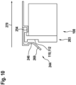
    • Fig. 10 eine zweite Entnahmemöglichkeit für den Akkupack nach Fig. 7;
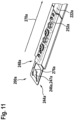
    • Fig. 11 eine alternative Ausführungsform einer Sicherungseinheit für die Verbindungsvorrichtung nach Fig. 3;
    • Fig. 12 eine perspektivische Vorderansicht des Verbindungsmittels gemäß Fig. 4;
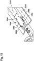
    • Fig. 13 eine perspektivische Ansicht eines Akkupacks zu Beginn eines Verbindungsprozesses;
    • Fig. 14 ein Längsschnitt durch den Akkupack und die Verbindungsvorrichtung im entriegelten und gesicherten Zustand;
    • Fig. 15 ein Längsschnitt durch den Akkupack und die Verbindungsvorrichtung im entriegelten Zustand nach einem Lösen der Sicherung;
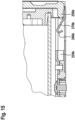
    • Fig. 16 eine Draufsicht auf eine Verbindungsvorrichtung mit einer weiteren alternativen Ausführungsform einer Sicherungseinheit;
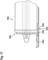
    • Fig. 17 eine Seitenansicht eines Akkupacks nach Fig. 2 im durch die Sicherungseinheit gemäß Fig. 16 gesicherten Zustand;
    • Fig. 18 eine Draufsicht auf eine Verbindungsvorrichtung mit einer weiteren alternativen Ausführungsform einer Sicherungseinheit;
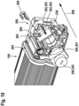
    • Fig. 19 eine perspektivische Ansicht eines Akkupacks nach Fig. 2 im mit der Verbindungsvorrichtung nach Fig. 6 verbundenen Zustand mit einem Aufnahmegehäuse einer Betätigungseinheit in einer Explosionsdarstellung;
    • Fig. 20 ein Querschnitt durch das Aufnahmegehäuse gemäß Fig. 19;
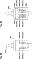
    • Fig. 21 eine alternative Ausführungsform einer Betätigungseinheit für ein Aufnahmegehäuse in einer schematischen Ansicht;
    • Fig. 22 eine alternative Ausführungsform eines Aufnahmegehäuses für eine Betätigungseinheit im mit der Betätigungseinheit nach Fig. 21 verbundenen Zustand;
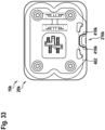
    • Fig. 23 eine perspektivische Ansicht einer weitere Ausführungsform eines Aufnahmegehäuses mit einer Betätigungseinheit in einer ersten Position;
    • Fig. 24 eine weitere Ausführungsform eines Aufnahmegehäuses mit einer Betätigungseinheit in einer zweiten Position;
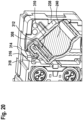
    • Fig. 25 ein Querschnitt durch ein Gehäuse des Akkupacks gemäß Fig. 2;
    • Fig. 26 eine vergrößerte Darstellung eines Ausschnitts des Gehäuses nach Fig. 25;
    • Fig. 27 ein Querschnitt durch eine alternative Rippenstruktur für ein Gehäuse eines Akkupacks;
    • Fig. 28 ein Querschnitt durch eine weitere alternative Rippenstruktur für ein Gehäuse eines Akkupacks;
    • Fig. 29 ein Querschnitt durch eine weitere alternative Rippenstruktur für ein Gehäuse eines Akkupacks;
    • Fig. 30 ein Querschnitt durch eine weitere alternative Ausführungsform eines Gehäuses für einen Akkupack;
    • Fig. 31 eine Vorderansicht des Akkupacks nach Fig. 2;
    • Fig. 32 eine Rückansicht des Akkupacks nach Fig. 2;
    • Fig. 33 eine schematische Abbildung einer alternativen Ausführungsform eines Rahmens eines Elektrofahrrads für ein Verbindungsmittel nach Fig. 31;
    • Fig. 34 perspektivische Ansichten einer alternativen Ausführungsform der Verbindungsmittel für den Akkupack nach Fig. 2;
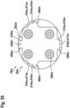
    • Fig. 35 eine schematische Ansicht einer weiteren alternativen Ausführungsform eines Verbindungsmittels für einen Akkupack;
    • Fig. 36 eine schematische Ansicht einer weiteren alternativen Ausführungsform eines Verbindungsmittels für einen Akkupack;
    • Fig. 37 eine Vorderansicht einer weiteren Ausführungsform eines Verbindungsmittels für einen Akkupack mit einer Entnahmehilfe;
    • Fig. 38 eine perspektivische Ansicht des Verbindungsmittels nach Fig. 37;
    • Fig. 39 eine alternative Ausführungsform einer Oberflächenstruktur einer Entnahmehilfe;
    • Fig. 40 eine weitere alternative Ausführungsform einer Oberflächenstruktur einer Entnahmehilfe;
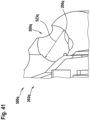
    • Fig. 41 eine weitere alternative Ausführungsform einer Oberflächenstruktur einer Entnahmehilfe.
    Beschreibung der Ausführungsbeispiele
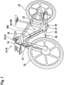
  • In Fig. 1 ist eine perspektivische Ansicht eines Verbrauchers 14 in Form eines Elektrofahrrads 16 gezeigt. Das Elektrofahrrad 16 kann beispielsweise als ein Pedelec oder als ein E-Bike ausgebildet sein.
  • Das Elektrofahrrad 16 weist ein Gehäuse in Form eines Rahmens 20 bzw. eines Fahrradrahmens auf. Mit dem Rahmen 20 sind zwei Räder 22 verbunden. Der Rahmen 20 umfasst mehrere Rahmenteile, insbesondere ein Unterrohr 21, ein Oberrohr und ein Sattelrohr. Zudem weist das Elektrofahrrad 16 einen Energiespeicher 24 in Form eines Akkupacks 100 auf. Zudem weist das Elektrofahrrad 16 eine Antriebseinheit 26 auf, die einen Elektromotor beziehungsweise einen Hilfsmotor umfasst. Der Elektromotor ist vorzugsweise als ein Permanentmagneterregter, bürstenloser Gleichstrommotor ausgebildet. Der Elektromotor ist beispielhaft als ein Mittelmotor ausgebildet, wobei auch ein Nabenmotor oder dergleichen denkbar ist. Das Elektrofahrrad 16, insbesondere die Antriebseinheit 26 des Elektrofahrrads 16, wird über den Energiespeicher 24 mit Energie versorgt. Der Akkupack 100 ist beispielhaft im Rahmen 20 integriert ausgebildet sein. Der Akkupack 100 ist dabei als Wechselakkupack ausgebildet, der über eine Verbindungsvorrichtung 200 lösbar mit dem Elektrofahrrad 16 verbindbar ausgebildet ist.
  • Die Antriebseinheit 26 umfasst eine Steuereinheit (nicht dargestellt), die zur Steuerung oder Regelung des Elektrofahrrads 16, insbesondere des Elektromotors, ausgebildet ist. Das Elektrofahrrad 16 weist eine Tretkurbel 28 auf. Die Tretkurbel 28 weist eine Tretkurbelwelle (nicht dargestellt) auf. Die Steuereinheit des Elektrofahrrads 16 ist mit einer Sensoreinheit (nicht dargestellt) verbunden. Die Sensoreinheit des Elektrofahrrads 16 umfasst beispielhaft mehrere Sensorelemente, wie einen Drehmomentsensor, einen Bewegungssensor, beispielsweise in Form eines Beschleunigungssensors, und einen Magnetsensor.
  • Die Steuereinheit und die Antriebseinheit 26 mit dem Elektromotor und der Tretkurbelwelle sind in einem mit dem Rahmen 20 verbundenen Antriebsgehäuse 27 angeordnet. Die Antriebsbewegung des Elektromotors wird vorzugsweise über ein Getriebe (nicht dargestellt) auf die Tretkurbelwelle übertragen, wobei die Größe der Unterstützung durch die Antriebseinheit 26 mittels der Steuereinheit gesteuert oder geregelt wird. Die Steuereinheit ist dazu ausgebildet, die Antriebseinheit 26 derart anzusteuern, dass der Fahrer des Elektrofahrrads 16 beim Pedalieren unterstützt wird. Vorzugsweise ist die Steuereinheit durch den Fahrer bedienbar ausgebildet, sodass der Fahrer den Unterstützungsgrad einstellen kann.
  • Die Steuereinheit und die Sensoreinheit sind einer Elektronik (nicht dargestellt) des Elektrofahrrads 16 zugeordnet. Die Elektronik umfasst beispielhaft eine Leiterplatte, auf der eine Recheneinheit in Form einer CPU, eine Speichereinheit und die Sensoreinheit angeordnet ist. Die Elektronik ist beispielhaft vollständig in dem Antriebsgehäuse 27 der Antriebseinheit 26 angeordnet. Es ist allerdings auch denkbar, dass die Elektronik nur teilweise im Antriebsgehäuse 27 angeordnet ist und Komponente der Elektronik an anderen Bereichen des Elektrofahrrads 16 angeordnet sind. Zudem ist auch eine Anordnung der Elektronik außerhalb des Antriebsgehäuses 27 denkbar.
  • Das Elektrofahrrad 16 umfasst zudem beispielhaft einen Boardcomputer 30, der an einem Lenker 32 des Elektrofahrrads 16 angeordnet ist. Der Boardcomputer 30 ist teilweise lösbar mit dem Elektrofahrrad 16 ausgebildet. Der Boardcomputer 30 umfasst eine Anzeigeeinheit 34, die zur Anzeige von Informationen ausgebildet ist. Der Boardcomputer 30 umfasst zudem ein Bedienelement (nicht dargestellt), über das der Benutzer beziehungsweise der Fahrer den Boardcomputer 30 und/oder das Elektrofahrrad 16 steuern kann. Das Bedienelement ist beispielhaft als ein berührungsempfindlicher Bildschirm ausgebildet. Es ist aber ebenso denkbar, dass das Bedienelement des Boardcomputers 30 aus Knöpfen oder Tasten ausgebildet ist. Der Boardcomputer 30 ist mit der Steuereinheit des Elektrofahrrads 16 derart verbunden, dass Informationen ausgetauscht werden können. Beispielsweise ist über die Anzeigeeinheit 34 eine von der Steuereinheit ermittelte Geschwindigkeit, ein eingestellter Unterstützungsgrad des Elektromotors, eine Routeninformation einer Navigationseinheit und ein Ladezustand des Energiespeichers 24 anzeigbar.
  • Beispielhaft ist der Akkupack 100 in dem Unterrohr 21 des Rahmens 20 angeordnet. Das Unterrohr 21 umfasst dabei einen Aufnahmeschacht 23, in welchem der Akkupack 100 im Wesentlichen vollständig im verbundenen Zustand angeordnet ist. Zur Verbindung wird der Akkupack 100 dabei in das Unterrohr 21 eingeschwenkt. Die Verbindung erfolgt über die Verbindungsvorrichtung 200, die beispielhaft vollständig im Rahmen 20 verbaut ist. Es ist ebenso denkbar, dass die Verbindungsvorrichtung 200 nur teilweise im Rahmen 20 des Elektrofahrrads 16 verbaut ist.
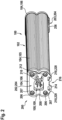
  • In Fig. 2 ist der im Rahmen 20 des Elektrofahrrads 16 aufgenommene Akkupack 100 in einer perspektivischen Ansicht gezeigt. Der Akkupack 100 umfasst ein Gehäuse 102, das beispielhaft drei Gehäuseteile 104 aufweist. Im Gehäuse 102 des Akkupacks 100 sind beispielhaft 20 Akkuzellen (nicht dargestellt) angeordnet, die über eine Serien- und Parallelschaltung elektrisch miteinander zu einem 36V Akkupack verbunden sind. Zudem weist der Akkupack 100 ein Batteriemanagementsystem (nicht dargestellt) auf, das zur Steuerung und Überwachung des Akkupacks 100 ausgebildet ist, wobei das Batteriemanagementsystem innerhalb des Gehäuses 102 des Akkupacks 100 angeordnet ist. Das Gehäuse 102 weist ein mittleres Gehäuseteil 105 auf, das beispielhaft rohrförmig mit einem an die aufgenommenen Akkuzellen angepassten Querschnitt ausgebildet ist. Das mittlere Gehäuseteil 105 ist einstückig ausgebildet und erstreckt sich im Wesentlichen entlang der gesamten Längserstreckung des Akkupacks 100. Stirnseitig weist das Gehäuse 102 zwei als Endplatten 106 ausgebildete Gehäuseteile 104 auf. Die Endplatten 106 sind beispielhaft mittels eines Laserdurchstrahlschweißprozesses mit dem mittleren Gehäuseteil 105 verbunden. Es wären alternativ aber auch andere Verbindungsarten, beispielsweise eine Verschraubung, denkbar.
  • Die Verbindungsvorrichtung 200 zur Verbindung des Akkupacks 100 mit dem Elektrofahrrad 16 weist akkupackseitige Komponenten, die dem Akkupack 100 zugeordnet sind, und fahrradseitige Komponenten, die dem Elektrofahrrad 16 zugeordnet sind, auf. In diesem Zusammenhang soll unter zugeordnet verstanden werden, dass die Komponente im normalen Gebrauch an dem Akkupack 100 beziehungsweise an dem Elektrofahrrad 16 befestigt ist.
  • Die Verbindungsvorrichtung 200 weist beispielhaft zwei akkupackseitige Komponenten auf. Alternativ wäre auch nur eine akkupackseitige Komponente oder mehrere akkupackseitige Komponenten denkbar. Die akkupackseitigen Komponenten sind beispielhaft als Verbindungsmittel 202, 203 ausgebildet. Die Verbindungsmittel 202, 203 sind beispielhaft in Form von Verbindungsplatten 204 ausgebildet, die an den Endplatten 106 des Akkupacks 100 befestigt sind. Die Befestigung erfolgt dabei über eine Schraubverbindung, wobei auch eine andere kraft- und/oder formschlüssige Verbindung oder ein Stoffschluss denkbar ist. Es ist ebenfalls denkbar, dass das Verbindungsmittel 202, 203 einstückig oder einteilig mit dem Gehäuse 102 des Akkupacks 100 ausgebildet ist. Beispielhaft ist denkbar, dass die Endplatten 106 als Verbindungsmittel 202, 203 ausgebildet sind und deren Funktion übernehmen.
  • Die Verbindungsmittel 202, 203 sind dabei unterschiedlich ausgebildet und unterscheiden sich dabei insbesondere in ihren Funktionen. Das erste oder vordere Verbindungsmittel 202 ist an der Endplatte 106 des Akkupacks 100 angeordnet, die die elektrische Schnittstelle 108 des Akkupacks 100 umfasst. Die elektrische Schnittstelle 108 des Akkupacks 100 ist zur elektrischen Verbindung des Akkupacks 100 mit dem Elektrofahrrad 16, insbesondere zur Leistungsversorgung und/oder zum Informationsaustausch, ausgebildet. Die elektrische Schnittstelle 108 des Akkupacks 100 umfasst beispielhaft eine Buchse 109.
  • Die Verbindungsmittel 202, 203 sind beispielhaft einstückig ausgebildet. Die Verbindungsmittel 202, 203 sind zudem beispielhaft aus einem Kunststoff ausgebildet, insbesondere aus einer Hartplastik.
  • Das Verbindungsmittel 202 weist beispielhaft vier Befestigungselementaufnahmen 206 auf, die zur Befestigung des Verbindungsmittels 202 an dem Gehäuse 102 des Akkupacks 100, insbesondere an der Endplatte 106, ausgebildet ist. Die Befestigungselementaufnahmen 206 sind beispielhaft als kreisförmige Aussparungen für Schrauben 207 ausgebildet.
  • Zudem weist das Verbindungsmittel 202 eine Durchgangsöffnung 208 im Bereich der elektrischen Schnittstelle 108 des Akkupacks 100 auf, um eine elektrische Verbindung mit einer korrespondierenden elektrischen Schnittstelle des Elektrofahrrads 16 zu ermöglichen.
  • Weiterhin umfasst das Verbindungsmittel 202 ein Verriegelungselement 210 einer Verriegelungseinheit 212 zur lösbaren Verriegelung des Akkupacks 100 an dem Elektrofahrrad 16, ein Führungselement 214 einer Führungseinheit 216 zur Führung des Akkupacks 100 während des Verbindungsvorgangs mit dem Elektrofahrrad 16 und zwei beispielhaft L-förmige Aussparungen 218 zur Zentrierung des Akkupacks 100. Die L-förmige Aussparungen 218 sind zudem als Linearlagerelemente 220 ausgebildet, die im verbundenen Zustand den Akkupack 100 lagern und im Fall von Vibrationen die auftretenden Kräfte aufnehmen.
  • In Fig. 3 sind die fahrradseitigen Komponenten der Verbindungsvorrichtung 200 in einer Seitenansicht gezeigt. Die fahrradseitigen Komponenten der Verbindungsvorrichtung 200 umfassen beispielhaft ein Führungselement 221 in Form einer Führungsschiene 222 mit benachbarten Führungsnuten 223 (siehe beispielsweise Fig. 6), die der Führungseinheit 216 der Verbindungsvorrichtung 200 zugeordnet ist. Die Befestigung des Führungsschiene 222 im Rahmen des Elektrofahrrads 16 erfolgt beispielhaft über eine Schraubverbindung 224.
  • Zudem umfasst die Verbindungsvorrichtung 200 einen Stecker 226, der einer elektrischen Schnittstelle 36 des Elektrofahrrads 16 zugeordnet ist und zu der elektrischen Schnittstelle 108 des Akkupacks 100 korrespondiert. Der Stecker 226 ist dabei lösbar mit der Führungseinheit 216 verbunden. Die elektrische Schnittstelle 36 des Elektrofahrrads 16 ist mittels eines mehrteiligen Verbindungsmittels 228 am Rahmen 20 des Elektrofahrrads 16 befestigt. Die Befestigung erfolgt dabei beispielhaft über eine Verschraubung, insbesondere über die gleiche Schraubverbindung 224, die auch für die Führungsschiene 222 verwendet wird. Das Verbindungsmittel 228 umfasst dabei ein Führungselement 230, das derart ausgebildet ist, dass die Führungskontur der Führungsschiene 222 fortgeführt wird. Das Führungselement 230 des Verbindungsmittels 228 ist aus einem Metall ausgebildet. Alternativ wäre ebenso denkbar, dass Führungselement 230 aus einem Kunststoff auszubilden.
  • Das Verbindungsmittel 228 umfasst zudem eine Gehäuseeinheit 232, die optional in unterschiedlichen Konfigurationen oder alternativ zu weiteren nicht dargestellten Gehäusemodulen montierbar ist. Der Stecker 226 ist lösbar mit der Gehäuseeinheit 232 verbunden. Insbesondere ist die Gehäuseeinheit 232 auch für andere Stecker ausgelegt, sodass die Verbindungsvorrichtung 200 auch für andere Akkupacks anpassbar ist. Alternativ oder zusätzlich kann die Gehäuseeinheit 232 auch in einer anderen Konfiguration, beispielsweise um 90° gedreht verbaut werden. Das Verbindungsmittel 228 umfasst zudem ein beweglich gelagertes Verriegelungselement 274 (siehe Fig. 8) welches der Verriegelungseinheit 212 der Verbindungsvorrichtung 200 zugeordnet ist. Das Verriegelungselement 274 ist in der Gehäuseeinheit 232 angeordnet. Zudem umfasst die Gehäuseeinheit 232 beispielhaft zwei Steckeraufnahmen 234 zur Aufnahme von weiteren Steckern 236 des Elektrofahrrads 16, über die der Akkupack 100 elektrisch über Kabelelemente mit weiteren Komponenten des Elektrofahrrads 16 verbindbar ist.
  • Weiterhin weist die Gehäuseeinheit 232 ein Aufnahmegehäuse 238 für eine Betätigungseinheit 240 auf. Das Aufnahmegehäuse 238 ist vorzugsweise derart ausgebildet, dass es in unterschiedlichen Konfigurationen beziehungsweise Ausrichtungen montierbar ist. Die Betätigungseinheit 240 ist zur Betätigung der Verriegelungseinheit 212 ausgebildet, wobei mittels einer Betätigung der Betätigungseinheit 240 eine Verriegelung zwischen dem Akkupack 100 und dem Elektrofahrrad 16 lösbar ist. Die Betätigungseinheit 240 ist beispielhaft als ein Schloss 242 ausgebildet, das über einen Schlüssel 241 (siehe beispielsweise Fig. 21) betätigbar ist. Die Betätigungseinheit 240 ist mechanisch mit der Verriegelungseinheit 212 gekoppelt.
  • Zudem umfasst die Verbindungsvorrichtung 200 eine Sicherungseinheit 244, die zur Sicherung des Akkupacks 100 im entriegelten Zustand ausgebildet ist. Die Sicherungseinheit 244 umfasst ein Sicherungselement 246, das an einem weiteren Verbindungsmittel 248 angeordnet ist, wobei das weitere Verbindungsmittel 248 beispielhaft an einer gegenüberliegenden Seite der Führungsschiene 222 mit dieser ebenfalls über eine Schraubverbindung angeordnet ist. Die Sicherungseinheit 244 ist dazu ausgebildet, den Akkupack 100 im entriegelten Zustand zu sichern. Das Sicherungselement 246 ist beispielhaft als eine metallische Blattfeder 250 ausgebildet.
  • Das weitere Verbindungsmittel 248 umfasst zudem analog zu dem Verbindungsmittel 228 ein Führungselement 252, das zu der Führungsschiene 222 korrespondiert. Zudem umfasst das Verbindungsmittel 248 stirnseitig ein Halteelement 254, wobei der Akkupack 100, insbesondere ein Verbindungsmittel 202 des Ackupacks 100, im verriegelten Zustand durch das Halteelement 254 gehalten wird.
  • Das Halteelement 254 ist als eine stirnseitige Öffnung ausgebildet, die einen im Wesentlichen U-förmigen Querschnitt aufweist.
  • Die Verriegelungseinheit 212 ist an einem ersten Abschnitt 1, insbesondere an einem vorderen Abschnitt, der Führungseinheit 216 angeordnet. Die Sicherungseinheit 244 ist an einem zweiten Abschnitt 2, insbesondere an einem hinteren Abschnitt, der Führungseinheit 216 angeordnet. Im ersten Abschnitt 1 ist dabei ein Abstand zu der Verriegelungseinheit 212 kleiner als ein Abstand zu der Sicherungseinheit 244. Die Führungseinheit 216 kann dabei wie in dieser Ausführungsform beschrieben mehrere Führungselemente oder alternativ auch nur ein einziges Führungselement aufweisen. Die Länge der Führungseinheit 216 entspricht im Wesentlichen dem größtmöglichen Abstand zwischen den am weitesten entfernten Führungselementen. Die Länge der Führungseinheit 216 entspricht beispielhaft im Wesentlichen einer Länge des Akkupacks 100. Es ist allerdings ebenfalls denkbar, dass der Akkupack 100 nur über einen kleinen Bereich geführt wird, beispielsweise nur 10% seiner Länge oder weniger. Der erste Abschnitt 1 und der zweite Abschnitt 2 der Führungseinheit 216 erstrecken sich insbesondere ausgehend von den unterschiedlichen Enden der Führungseinheit 216.
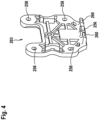
  • In Fig. 4 ist das zweite oder hintere Verbindungsmittel 203 des Akkupacks 100 mit einem zu dem Halteelement 254 korrespondierenden Eingriffsmittel 256 in einer perspektivischen Ansicht gezeigt. Analog zu dem ersten Verbindungsmittel 202 des Akkupacks 100 umfasst das Verbindungsmittel 203 vier Befestigungselemente 258 in Form von Schraubaufnahmen für Schrauben auf, die zur Verbindung mit der korrespondierenden Endplatte 106 des Akkupacks 100 vorgesehen sind. Das Halteelement 254 erstreckt sich dabei in Richtung des Akkupacks 100 unterhalb des Gehäuses 102 des Akkupacks 100. Benachbart zu dem Halteelement 254 weist das Verbindungsmittel 202 zwei weitere Halteelemente 260 auf, die insbesondere zum Entgegenwirken einer Verkippung des Akkupacks 100 im verbundenen Zustand um die Längsachse des Akkupacks 100 vorgesehen sind. Zudem wird das Eingriffsmittel 256 beim Einführen derart ausgerichtet, dass dieses mittig in das Halteelement 254 eingreift. Dies erfolgt insbesondere durch die weiteren Halteelemente 260, die etwas länger ausgebildet sind und zusätzliche Entformungsschrägen aufweisen.
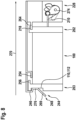
  • In Fig. 5 ist das mit der Führungsschiene 222 verbundene weitere Verbindungsmittel 248 in einer perspektivischen Ansicht in einer Perspektive ausgehend von dem Rahmen 20 beziehungsweise von unten gezeigt. Das weitere Verbindungsmittel 248 ist beispielhaft derart ausgebildet, dass das Sicherungselement 246 der Sicherungseinheit 244 und das Führungselement 252 der Führungseinheit 216 unabhängig voneinander mit der Führungsschiene 222 und/oder dem Rahmen 20 des Elektrofahrrads 16 verbindbar sind. Das Führungselement 252 wird dabei über die Verschraubung 224 sowohl mit der Führungsschiene 222 als auch mit der Rahmen 20 verbunden. Das Sicherungselement 246 wird beispielhaft direkt nur an der Führungsschiene 222 über eine kraft- und formschlüssige Verbindung, beispielhaft über ein Einklemmen, verbunden.
  • In Fig. 6 ist das Verbindungsmittel 228 der Verbindungsvorrichtung 200 in einer perspektivischen Ansicht gezeigt. Das bewegliche Verriegelungselement 274 ist dabei in einer Aufnahme 262 für das korrespondierende Verriegelungselement 210 an der Verbindungsplatte 204 des Akkupacks 100 angeordnet. Zudem weist das Verbindungsmittel 228 zwei Linearlagerelemente 264 auf, die sich ausgehend von einer ersten Verbindungsebene 266 (siehe Fig. 7), an welcher das Verbindungsmittel 228 des Verbrauchers 14 und das Verbindungsmittel 202 im verriegelten Zustand im Wesentlichen aneinander anliegen, in Richtung des Akkupacks 100 erstrecken und im Querschnitt korrespondierend L-förmig ausgebildet sind. Alternativ sind auch andere Geometrien, beispielhaft rechteckig oder quadratisch denkbar.
  • In Fig. 7 ist die Verbindungsvorrichtung 200 mit dem Akkupack 100 im verriegelten Zustand in einer Seitanansicht gezeigt.
  • Zur Verbindung wird der Akkupack 100 relativ zum Elektrofahrrad 16 um ein Verbindungsachse 268 zunächst eingeschwenkt. Die Verbindungsachse 268 ist dabei zur Veranschaulichung an einem Punkt eingezeichnet, wobei toleranzbedingt das Einschwenken auch in einem benachbarten Bereich erfolgen kann. Beim Einschwenken wird das nach außen abstehende Verriegelungselement 210 des Akkupacks 100 in die korrespondierende Aufnahme 262 der Verbindungsvorrichtung 200 im Rahmen 20 des Elektrofahrrads 16 eingeführt. Zudem kann bereits eine teilweise Verbindung der elektrischen Schnittstelle stattfinden.
  • Nachdem der Akkupack 100 in den Rahmen eingelegt wurde, liegt der Akkupack 100 auf der Führungsschiene 222 auf und kann durch eine Linearbewegung in Verbindungsrichtung 270 in Richtung des Verbindungsmittels 228 verschoben werden. Durch die Relativbewegung in Richtung des Verbindungsmittels 228 wird die Verriegelungseinheit 212 ausgelöst und der Akkupack 100 am Elektrofahrrad 16 verriegelt. Zudem wird die Buchse 109 des Akkupacks 100 mit dem Stecker 226 des Elektrofahrrads 16 verbunden. Die Beweglichkeit des Akkupacks 100 entlang der Verbindungsrichtung 270 ist dabei durch das Verbindungsmittel 228 und das Sicherungselement 246 begrenzt. Das Sicherungselement 246 ist allerdings elastisch ausgebildet und kann durch Beaufschlagung des Sicherungselements 246 mit einer Kraft entgegen der Verbindungsrichtung 270 derart bewegt werden, dass ein Bewegungsraum 271 entlang der Verbindungsrichtung 270 geringfügig vergrößerbar ist. Die Kraft auf das Sicherungselement 246 kann dabei direkt durch den Benutzer über den einstückig mit dem Sicherungselement 246 ausgebildeten Betätigungsbereich 269 erfolgen.
  • Die Verriegelung kann über eine Betätigung der Betätigungseinheit 240 gelöst werden. Die Betätigungseinheit ist dabei beispielhaft manuell durch das Einführen des Schlüssels in den hierzu vorgesehenen Schlitz des Schlosses 242 betätigbar. Beispielhaft wird durch ein Drehen des Schlüssels im Schloss 242 die Verriegelung gelöst und das beweglich im Verbindungsmittel 228 gelagerte Verriegelungselement derart betätigt, dass der Akkupack 100 entgegen der Verbindungsrichtung 270 ausgeworfen wird.
  • In Fig. 8 ist der Akkupack im mit der Verbindungsvorrichtung 200 im entriegelten, aber verbundenen Zustand in einer schematischen Ansicht gezeigt. Das beweglich gelagerte Verriegelungselement 274 ist mit einem nicht dargestellten Federelement entgegen der Verbindungsrichtung 270 vorgespannt, sodass der Ackupack 100 beim Übergang vom verriegelten Zustand in den entriegelten Zustand entgegen der Verbindungsrichtung 270 aus dem Verbindungsmittel 228 herausgeschoben wird, bis der Akkupack 100 am Sicherungselement 246 des weiteren Verbindungsmittels 248 anschlägt. Die Sicherungseinheit 244 stellt somit im Wesentlichen eine Sekundärverriegelung bereit. Hierzu ist ein Bereich des Sicherungselements 246 als ein Anschlagelement 276 ausgebildet. Insbesondere weist der Akkupack 100, insbesondere da Verbindungsmittel 203 des Akkupacks 200, ein korrespondierendes Sicherungselement 110 beispielhaft in Form einer beispielhaft rechteckigen Vertiefung 112 auf, in welche das Anschlagelement 276 im verbundenen beziehungsweise im entriegelten Zustand eingreift. Vorteilhaft wird durch die Sicherungseinheit 244 sichergestellt, dass der Akkupack 100 durch das Lösen der Verriegelung nicht ungewollt aus dem Rahmen 20 des Fahrrads herausfällt. Ein Lösen der Verbindung durch ein Ausschwenken ist in diesem Zustand zunächst nicht möglich. Die Verbindungsvorrichtung 200 ist beispielhaft derart ausgebildet, dass der Benutzer zwei Möglichkeiten zum Lösen der Verbindung hat.
  • Die erste Möglichkeit ist in Fig. 9 in einer schematischen Ansicht gezeigt. Hierzu drückt der Benutzer mit einer Kraft auf den Betätigungsbereich 269 des Sicherungselements 246 und verschiebt somit das Sicherungselement 246 entgegen der Verbindungsrichtung 270 und vergrößert damit den Bewegungsraum 271 des Akkupacks 100 im verbundenen Zustand. Mittels des vergrößerten Bewegungsraums 271 kann die Verbindung des Akkupacks 100 mit dem Elektrofahrrad 16 gelöst und dieser entnommen werden.
  • Die zweite Möglichkeit den Akkupack 100 zu entnehmen ist in Fig. 10 in einer schematischen Ansicht gezeigt. Der Akkupack 100 wird hierzu von einem Benutzer um eine kleine Wegstrecke derart in Verbindungsrichtung 270 und entgegen der Federkraft des Federelements des drehbar gelagerten Verriegelungselements 274 bewegt, dass weder das Sicherungselement 246 noch das Halteelement 254 des Verbindungsmittels 248 einen Kraft- und/oder Formschluss mit dem Akkupack 100, insbesondere dem Verbindungsmittel 203 des Akkupacks 100, bildet und somit der Akkupack 100 ausschwenkbar ist.
  • Es ist ebenso denkbar, dass die Verbindungsvorrichtung 200 derart ausgebildet ist, dass nur eine dieser Möglichkeiten besteht. Beispielhaft durch ein nicht bewegliches Sicherungselement 246 oder durch eine Anordnung des Sicherungselements 246 und des Halteelements 254, die derart gestaltet ist, dass nur durch eine Betätigung des Sicherungselements 246 ein Lösen möglich ist.
  • Die in Fig. 1 bis Fig. 10 beschriebene Verbindungsvorrichtung 200 ist für eine Verbindung des Akkupacks 100 über eine Schwenkbewegung in den Rahmen 20, beispielhaft in das Unterrohr des Rahmens 20, ausgebildet. Im Anschluss an die Schwenkbewegung wird diese durch eine Linearbewegung entlang der Verbindungsrichtung 270 ergänzt, um den Akkupack 100 mit dem Elektrofahrrad 16 mechanisch und elektrisch zu verbinden und zu verriegeln. Der Rahmen 20 weist hierzu eine seitliche Öffnung (nicht dargestellt), beispielsweise auf der Unterseite aus. Die Länge dieser Öffnung entspricht dabei insbesondere im Wesentlichen der Länge des Akkupacks 100.
  • In Fig. 11 ist eine alternative Ausführungsform der zuvor beschriebenen Sicherungseinheit 244 in einer perspektivischen Teilansicht gezeigt. Diese alternative Ausführungsform ist dabei für Rahmen von Elektrofahrrädern vorgesehen, bei denen der Akkupack 100 nicht seitlich eingeschwenkt, sondern nur linear eingeschoben wird. Dies kann beispielhaft über eine Öffnung des Rahmens im Bereich der Antriebseinheit erfolgen. Vorteilhaft kann mit der angepassten Sicherungseinheit 244 die Verbindungsvorrichtung 200 ohne weitere Anpassungen im Bereich der Verbindungsmittel 202, 203 am Akkupack 100 und ohne Anpassungen am vorderen Verbindungsmittel 228 erfolgen.
  • Die Sicherungseinheit 244a umfasst ein alternatives Sicherungselement 246a, das beispielhaft wie zuvor beschrieben einem Verbindungsmittel 248a zugeordnet ist, welches mit einer Führungsschiene 222a verbunden ist. Das Verbindungsmittel 248a umfasst dabei wie zuvor beschrieben ein Führungselement 252a zur Führung des Akkupacks 100 beim Verbindungsprozess entlang oder entgegen der Verbindungsrichtung 270a.
  • Das Sicherungselement 246a ist beispielhaft metallisch ausgebildet, wobei es auch denkbar ist, das Sicherungselement 246a aus einem anderen Werkstoff, beispielhaft aus Kunststoff, anzufertigen. Das Sicherungselement 246a ist als ein federnder Anschlag 247a ausgebildet und weist ein Anschlagelement 276a auf. Das Anschlagelement 276a ist beispielhaft an einer Spitze des Sicherungselements 246a angeordnet. Das Sicherungselement 246a ist derart ausgebildet, dass das Anschlagelement 276a durch Beaufschlagung mit einer Kraft quer zur Verbindungsrichtung 270a nach unten, insbesondere in Richtung der Führungsschiene 222a, bewegbar ist.
  • In Fig. 12 ist eine perspektivische Ansicht des Verbindungsmittels 203 des Akkupacks 100, das zur Verbindung mit der Sicherungseinheit 244a im entriegelten Zustand vorgesehen ist.
  • Das Verbindungsmittel 203 weist neben dem bereits beschriebenen Sicherungselement 110, welches im Wesentlichen mittig im Verbindungsmittel 203 angeordnet ist, ein zweites Sicherungselement 114 auf. Das zweite Sicherungselement 114 ist dabei für das Sicherungselement 246a des alternativen Sicherungseinheit 244a vorgesehen. Vorteilhaft kann somit das Verbindungsmittel 203 für beide Sicherungseinheit 244, 244a verwendet und somit der Akkupack 100 nach Bedarf angepasst werden. Das zweite Sicherungselement 114 ist beispielhaft ebenfalls als eine rechteckige Vertiefung 116 ausgebildet. Das erste Sicherungselement 110 und das zweite Sicherungselement 114 sind beispielhaft über eine Trennwand 118 voneinander getrennt. Die Trennwand 118 bildet zumindest für das Sicherungselement 246a der alternativen Sicherungseinheit 244a eine zusätzliche Gegenkontur.
  • In Fig. 13 ist der Akkupack 100 zu Beginn des Verbindungsprozess gezeigt, in welchem der Akkupack 100 mit dem Verbindungsmittel 202a voraus in den Rahmen des Elektrofahrrads geschoben wird. Das Sicherungselement 246a ist derart ausgebildet, dass dieses auch ohne Beaufschlagung mit einer Kraft eine kleinere Höhe als die Führungsschiene 222a aufweist und somit niedriger liegt als die Führungsschiene 222a. Der Akkupack 100 kann somit ohne zusätzlichen Krafteintrag eingeschoben werden. Es wäre allerdings auch denkbar, dass das Sicherungselement 246a höher ausgebildet ist und beim Verbindungsvorgang durch den Akkupack 100 heruntergedrückt wird. Um die Sicherung leichter zu Lösen weist das Anschlagelement 276a bevorzugt eine abgerundete Anschlagfläche auf. Das Lösen kann dabei manuell über eine direkte Betätigung des Sicherungselements 246a durch den Benutzer mit einem Finger oder indirekt über den Akkupack 100 beim Aufbringen einer Kraft entgegen der Verbindungsrichtung 270a.
  • In Fig. 14 ist eine alternative Ausführungsform des Verbindungsmittels 203b in einem Längsschnitt in einem entriegelten und gesicherten Zustand gezeigt. Das Verbindungsmittel 248a des Elektrofahrrads entspricht dabei dem zuvor beschriebenen Verbindungsmittel 248a mit der alternativen Sicherungseinheit 244a.
  • Das Verbindungsmittel 203b weist analog zu der vorherigen Ausführungsform ein erste Sicherungselement 110b und ein zweites Sicherungselement 114b auf. Das zweite Sicherungselement 114b unterscheidet sich dabei dadurch, dass das zweite Sicherungselement 114b als eine ebene Anschlagfläche 120b ausgebildet ist, die benachbart zu einer Schräge 122b angeordnet ist, entlang der das Sicherungselement 246a beim Lösen der Sicherung geführt wird.
  • In Fig. 15 ist das Verbindungsmittel 203b zu Beginn des Verbindungsvorgangs in einem Längsschnitt gezeigt. Während das vordere Verbindungsmittel 202 im Bereich der elektrischen Schnittstelle 108 des Akkupacks 100 ohne Beaufschlagung des Sicherungselements 246a verbindbar ist, wird das Sicherungselement 246a beim Einführen durch das zuvor beschriebene Eingriffsmittel 256b betätigt, wobei das Sicherungselement 246a hierzu eine Einfuhrschräge 278a aufweist.
  • In Fig. 16 ist eine weitere Ausführungsform der Sicherungseinheit 244c in einer Draufsicht gezeigt. Die Sicherungseinheit 244c ist wie in den unmittelbar zuvor beschriebenen Ausführungsformen für linear beziehungsweise rein axial aufgenommene Akkupacks 100 vorgesehen.
  • Das Sicherungselement 246c der Sicherungseinheit 244c ist im Gegensatz zu den vorherigen Sicherungselementen 246c nicht im zweiten Abschnitt 2 der Führungseinheit 216c, sondern im ersten Abschnitt 1 der Führungseinheit 216c angeordnet. Dadurch weist die die Sicherungseinheit 244c einen Abstand 280c von der Verriegelungseinheit 212c auf, der kleiner als 50% der Länge des Akkupacks 100 ist.
  • Das Sicherungselement 246c ist als ein Federelement, beispielhaft als einer Drahtfeder, ausgebildet. Das Sicherungselement 246c ist dabei derart ausgebildet, dass bei einer Beaufschlagung des Sicherungselements 246c durch den Ackupack 100 die Reibungskraft zwischen der Führungseinheit 216c und dem Ackupack 100 vergrößert wird. Das Sicherungselement 246c und der Akkupack 100 sind dabei derart ausgebildet, dass die Reibungskraft in Verbindungsrichtung 270c größer als in die entgegengesetzte Entnahmerichtung ausgebildet ist. Beispielhaft weist das Sicherungselement 246c eine Einfuhrschräge 278c auf die relativ zur Verbindungsrichtung 270c eine geringere Steigung aufweist als das ebenfalls als eine Schräge ausgebildete Anschlagelement 276c.
  • Das Sicherungselement 246c ist auf der Unterseite der Führungsschiene 222c montiert und ragt beispielhaft in die Führungsnut 223c einseitig seitlich hinein. Beim Verbinden oder Lösen des Akkupacks 100 wird das Sicherungselement 246c durch die axiale Bewegung des Akkupacks 100 in die Führungsschiene 222c hineingedrückt und dadurch bewegt.
  • In Fig. 17 ist eine Seitenansicht des Akkupacks 100 im entriegelten aber durch die Sicherungseinheit 244c gesicherten Zustand gezeigt. Der Akkupack 100 wird dabei durch die Verriegelungseinheit 212c derart ausgeworfen, dass der Akkupack 100, insbesondere das Verbindungsmittel 202 des Akkupacks 100, am Sicherungselement 246c, insbesondere am Anschlagelement 276c, zum Anliegen kommt und durch das Sicherungselement 246c gehalten wird. Hierzu ist das Verbindungsmittel 202 insbesondere derart geformt, dass es den Außendurchmesser des Akkupacks 100 bereichsweise vergrößert. Zum Lösen der Sicherung wird der Akkupack 100 durch den Benutzer gegriffen und entgegen der Verbindungsrichtung 270c gezogen.
  • In Fig. 18 ist eine weitere alternative Ausführungsform der Sicherungseinheit 244c in einer perspektivischen Ansicht gezeigt. Die Sicherungseinheit 244d ist dabei ebenfalls für die rein axiale/lineare Verbindung vorgesehen und im ersten Abschnitt 1 der Führungseinheit 216d angeordnet. Die Sicherungseinheit 244d umfasst dabei vier Sicherungselemente 246d, die als metallische Blattfedern ausgebildet sind. Die Sicherungselemente 246d sind beispielhaft mit der Führungsschiene 222d verbunden und ragen in die zwei gegenüberliegenden Führungsnuten 223d hinein.
  • Um eine modulare Lösung für unterschiedliche Rahmengeometrien und Verbauarten von unterschiedlichen Elektrofahrrädern zu ermöglichen ist die Verbindungsvorrichtung 200 gemäß Fig. 6 derart ausgebildet, dass die Betätigungseinheit 240 in unterschiedlichen Anordnungen relativ zur Führungseinheit 216 und/oder relativ zur Verriegelungseinheit 212 montierbar ist. Zum einen ist die Betätigungseinheit 240 in dem Aufnahmegehäuse 238 aufgenommen. Alternativ und nicht dargestellt ist es ebenso möglich, die Betätigungseinheit 240 um 90° verdreht und ohne das Aufnahmegehäuse zu verbinden, sodass das Schloss 242 nicht wie dargestellt seitlich sondern nach oben gerichtet ist. Da die Rahmen der Elektrofahrräder in der Regel eine Öffnung im Rahmen zur Betätigung des Schlosses brauchen, ist die Möglichkeit die Ausrichtung der Betätigungseinheit 240 modular anzupassen sehr vorteilhaft. Hierzu kann auf der Betätigungseinheit ein weiteres Bauteil montiert werden, das auf die bestehende Entriegelungsschnittstelle geschoben wird und eine Umlegung durch eine Schräge auf eine weitere Entriegelungsschnittstelle ermöglicht.
  • Um die Betätigungseinheit 240 beziehungsweise das Schloss 242 nicht nur auf unterschiedlichen Seiten, sondern auch in unterschiedlichen Einbautiefen anordnen zu können, ist die Verbindungsvorrichtung 200 derart ausgebildet, dass die Betätigungseinheit 240 an einer ersten Position 304 und an einer zweiten Position 304 innerhalb des Aufnahmegehäuses 238 entlang der Aufnahmerichtung 299 fixierbar ist, wie in Fig. 19 zu sehen.
  • Die Betätigungseinheit 240 weist hierzu ein erstes Verbindungselement 300 auf, das beispielhaft als eine kreisförmige Bohrung 301 ausgebildet ist. Das Aufnahmegehäuse 238 für die Betätigungseinheit 240 weist zwei zweite Verbindungselemente 302 auf, die beispielhaft als kreisförmige Aussparungen 303 ausgebildet sind.
  • Das Verbindungselemente 300, 302 sind dabei derart angeordnet, dass bei einem geradlinigen Einschieben der Betätigungseinheit 240 in das Aufnahmegehäuse 238 zunächst das vordere zweite Verbindungselement 302 mit dem ersten Verbindungselement 300 in der ersten Position 304 überlappt und bei einem weiteren Einschieben das hintere zweite Verbindungselement 302 in der zweiten Position 306 mit dem ersten Verbindungselement 300 überlappt.
  • Zudem weist die Verbindungsvorrichtung 200 ein Positionierungselement 308 auf, dass zur Fixierung der Betätigungseinheit 240 im Aufnahmegehäuse 238 in der ersten Position 304 und in der zweiten Position 306 ausgebildet ist, wobei die Betätigungseinheit 240 in der zweiten Position 306 ein größere Einbautiefe aufweist als in der ersten Position 304 aufweist.
  • In Fig. 20 ist ein Querschnitt durch die Verbindungsvorrichtung 200 bei einer Betätigungseinheit 240 im in der zweiten Position 306 fixierten Zustand gezeigt.
  • Das Positionierungselement 308 weist einen Fixierabschnitt 310 zur Fixierung des Positionierungselements 308 in der Betätigungseinheit 240 auf. Der Fixierabschnitt 310 ist beispielhaft im Wesentlichen stiftförmig ausgebildet und weist einen Federarm 312 auf, der im verbundenen Zustand eingedrückt ist und dadurch eine fixierende Vorspannkraft ausgebildet. Durch die Vorspannkraft entsteht ein Kraftschluss zwischen dem Positionierungselement 308 und dem ersten Verbindungselement 300 und dem Positionierungselement 308.
  • Zudem weist das Positionierungselement 308 einen Halteabschnitt 314 auf, das zur Befestigung des Positionierungselements 308 am Aufnahmegehäuse 238 ausgebildet ist. Der Halteabschnitt 314 ist beispielhaft als ein Rasthaken 316 ausgebildet, der zur Verbindung mit einer korrespondierenden Rastkontur 318 an der Außenfläche des Aufnahmegehäuses 238 ausgebildet ist. Der Halteabschnitt 314 und der Fixierabschnitt 310 sind über einen vorzugsweise elastischen Verbindungssteg 320 miteinander verbunden.
  • Zur Positionierung der Betätigungseinheit 240 im Aufnahmegehäuse 238 wird zunächst die Betätigungseinheit 240 linear in das Aufnahmegehäuse 238 bis zur ersten Position 304 oder bis zu zweiten Position 306 eingeschoben. Im Anschluss wird das Positionierungselement 308 mit dem Fixierabschnitt 310 voraus durch das zweite Verbindungselement 302 des Aufnahmegehäuses 238 in das erste Verbindungselement 300 der Betätigungseinheit 240 hineingeschoben. Die Einschubbewegung endet dabei mit dem Einschnappen des Halteabschnitts 314 des Positionierungselements 308 in die korrespondierende Rastkontur 318 am Aufnahmegehäuse 238. Zum Lösen der Verbindung kann der elastische Halteabschnitt 314 nach von einem Benutzer nach außen gebogen werden, um nach Lösen des Formschlusses das Positionierungselement 308 herauszuziehen.
  • In Fig. 21 ist eine alternative Ausführungsform einer Betätigungseinheit 240e gezeigt, die ebenfalls in unterschiedlichen Positionen in einem alternativen Aufnahmegehäuse 238e (siehe Fig. 22) für die Betätigungseinheit 240e fixierbar ist.
  • Im Unterschied zu den zwei diskreten Positionen im vorherigen Ausführungsbeispiel ist in dieser Ausführungsform eine stufenlose Einstellung der Position der Betätigungseinheit 240e im Aufnahmegehäuse 238e möglich. Die Betätigungseinheit 240e umfasst beispielhaft zwei erste Verbindungselemente 300e in Form von Langlöchern 322e, wobei in den Langlöchern 322e jeweils ein Positionierungselement 308e in Form einer Schraube 324e angeordnet ist. Die Positionierungselemente 308 sind dabei im unbefestigten Zustand zunächst beweglich im Langloch 322e angeordnet.
  • Das Aufnahmegehäuse 238e umfasst beispielhaft zwei zweite Verbindungselemente 302e, die ebenfalls als Langlöcher 326e ausgebildet sind, wobei die Langlöcher 326e des Aufnahmegehäuses 238e in ihrer Positionierung und Dimension zu den Langlöchern 322e der Betätigungseinheit 240e korrespondieren. Des Weiteren umfasst das Aufnahmegehäuse 238e zwei Fixierelemente 328e zur Verklemmung der Betätigungseinheit 240e am Aufnahmegehäuse 238e.
  • Im verbundenen Zustand kann die Betätigungseinheit 240e innerhalb der durch die Fixierelemente 328e gesetzten Grenzen relativ zu dem Aufnahmegehäuse 238e linear verschoben und durch die Schrauben 324e fixiert werden.
  • In Fig. 23 und in Fig. 24 ist eine weitere alternative Ausführungsform eines Aufnahmegehäuses 238f und einer Betätigungseinheit 240f gezeigt, die in unterschiedlichen Positionen zueinander fixierbar sind. Im Unterschied zu den vorherigen Ausführungsformen sind dabei die ersten Verbindungselemente 300f der Betätigungseinheit 240f und die zweiten Verbindungselemente 302f des Aufnahmegehäuses 238f direkt miteinander verbindbar und es wird kein zusätzliches Positionierungselement benötigt.
  • Die Verbindungselemente 300f, 302f weisen dabei jeweils eine Vielzahl von Rastelementen 330f, beispielhaft zehn Rastelemente 330f, auf. Vorteilhaft kann die Betätigungseinheit 240f dadurch in zehn unterschiedlichen Positionen im Aufnahmegehäuse 238f aufgenommen werden.
  • Die ersten Verbindungselemente 300f sind beispielhaft an einer innenliegenden Seite einer Kappe 332f angeordnet, die fest mit der Betätigungseinheit 240f verbunden ist. Die Kappe 332f und die Betätigungseinheit 240f können dabei einstückig ausgebildet sein. In dieser Ausführungsform erfolgt die feste Verbindung beispielsweise über einen Stoffschluss durch Verkleben. Vorteilhaft kann dadurch die Betätigungseinheit 240 gemäß Fig. 19 durch die Kappe 332f für weitere Konfigurationen angepasst werden. Die zweiten Verbindungselemente 302f sind auf einer Außenseite des Aufnahmegehäuses 238f angeordnet.
  • In Fig. 23 ist die Betätigungseinheit 240f beispielhaft in einer mittleren Position und in Fig. 24 in einer Endposition mit eine größtmöglichen Einbautiefe befestigt. Zur besseren Lagerung werden dabei beispielhaft zwei Abstandshalter 334f verwendet, die in das Aufnahmegehäuse 238f vor Montage der Betätigungseinheit 240f eingesetzt werden und auf denen die Betätigungseinheit 240f aufliegt. Die Abstandshalter 334f können beispielsweise elastisch aus einer Weichplastik oder auch aus einer Hartplastik ausgebildet sein. In der Endposition ist vorzugsweise kein Einsatz von Abstandshaltern 334f nötig.
  • In Fig. 25 ist das Gehäuse 102 des Akkupacks 100 in einem Querschnitt gezeigt. In dem Gehäuse 102 ist ein Zellenhalter 122 zur Aufnahme der Akkuzellen 124 angeordnet. Beispielhaft sind im Gehäuse 102 des Akkupacks 100 fünf Akkuzellen 124 nebeneinander angeordnet. Der Zellenhalter 122 weist Einzelzellenaufnahmen zur einzelnen Aufnahme von den Akkuzellen 124 auf. Zudem ist im Gehäuse 102 des Akkupacks 100 eine Leiterplatte 126 angeordnet, die einem Batteriemanagementsystem zugeordnet ist.
  • Im Querschnitt betrachtet folgt die Kontur des mittleren Gehäuseteils 105 des Ackupacks 100 im Wesentlichen der Form des Zellenhalters 122 beziehungsweise der Akkuzellen 124.
  • Das Gehäuse 102, insbesondere das mittlere Gehäuseteil 105, weist auf seiner Außenfläche 128 eine Rippenstruktur 130 auf. Die Rippenstruktur 130 umfasst dabei eine Vielzahl an Rippen 132 zwischen denen jeweils eine Nut 133 angeordnet ist. Die Rippen 132 erstrecken sich parallel zueinander und beispielhaft geradlinig entlang der gesamten Länge des mittleren Gehäuseteils 105. Vorteilhaft wird durch die Rippenstruktur 130 die Oberfläche des Gehäuses 102 vergrößert und dadurch die Abfuhr von Wärme aus dem inneren des Gehäuses 102 nach außen verbessert. Beispielhaft nimmt die Rippenstruktur einen Anteil von über 80% der Außenfläche 128 des Gehäuse 102 ein.
  • Das mittlere Gehäuseteil 105 besteht beispielhaft aus einem Kunststoff, insbesondere aus einer Hartplastik. Die Rippenstruktur 130 ist vorzugsweise einstückig mit dem Gehäuse 102, insbesondere dem mittleren Gehäuseteil 105, des Akkupacks 100 ausgebildet. Die Rippenstruktur 130 deckt vorzugsweise die gesamte Außenfläche 128 des mittleren Gehäuseteils 105 ab. Allerdings kann das Gehäuse 102 fertigungsbedingt oder als Platzhalter für Produkthinweise auch freie Flächen 134 aufweisen, die keine Rippenstruktur 130 umfassen.
  • Der Abstand zwischen dem mittleren Gehäuseteil 105 und dem Zellenhalter 122 ist dabei vorzugsweise kleiner als eine Dicke D des Gehäuseteils 104. Ein Ausschnitt der Rippenstruktur gemäß Fig. 24 ist in Fig. 26 in einem Querschnitt gezeigt.
  • Die Rippen 132 weisen dabei eine Höhe H und einen Abstand L voneinander auf. Der Abstand L ist dabei beispielhaft im Wesentlichen gleichmäßig ausgebildet. Beispielhaft ist die Rippenstruktur 130 derart ausgebildet, dass ein Verhältnis zwischen der Höhe H der Rippen 132 und der Dicke D der Rippen 132 ungefähr 0,4 beträgt.
  • Zudem ist der Abstand L der Rippen 132 voneinander derart gewählt, dass dieser kleiner als 20% eines Durchmessers der Akkuzellen 124 ist. Dies hat weiterhin einen positiven Effekt auf die Robustheit des Akkupacks 100, da durch eine Verformung der Vielzahl an Rippen 132 im Falle eines Sturzes die mechanische Energie wirksam vom Gehäuse 102 des Akkupacks 100 durch Verformung der Rippen 132 aufgenommen wird. Vorteilhaft ist die Rippenstruktur 130 auch in den gekrümmten Bereichen der Außenfläche 128 angeordnet, in welcher sich die benachbarten Rippen voneinander weg erstrecken und insbesondere den Wärmetransport weiter optimieren.
  • Die Rippen 132 und die Nuten 133 weisen beispielhaft eine runde Kantenform auf.
  • In Fig. 27 ist ein alternatives Profil einer Rippenstruktur 130g in einem Teilquerschnitt gezeigt. Die Rippenstruktur 130g weist dabei eckige Rippen 132g und eckige Nuten 133g auf.
  • In Fig. 28 ist ein weiteres alternatives Profil einer Rippenstruktur 130h gezeigt, wobei die Rippen 132h runde Kanten und die Nuten 133h eckige Kanten aufweisen. Es wäre ebenso denkbar, dass die Rippen 132h eckige Kanten und die Nuten 133h runde Kanten aufweisen.
  • In Fig. 29 ist ein weiteres alternatives Profil einer Rippenstruktur 130i gezeigt, bei der die Rippen 132i eine deutlich kleinere Breite aufweisen als die Nuten 133i und sich somit für den Betrachter eine im Wesentlichen konvexe Gestalt der Rippenstruktur 130i bildet.
  • In Fig. 30 ist ein Gehäuseteil 104j eines Gehäuses 102j für einen Akkupack in einem Querschnitt gezeigt, welches ein weiteres alternatives Profil einer Rippenstruktur 130j aufweist. Das Profil weist eine im Wesentlichen konvexe Form auf, die aufgrund der im Verhältnis zu der Dicke D des Gehäuseteils 104 geringen Höhe H der Rippen 132j kaum zu sehen ist, allerdings dennoch einen vorteilhaften Effekt hat.
  • Die Verbindungsmittel 202, 203 des Akkupacks 100 weisen jeweils zumindest einen Funktionsabschnitt 400 auf, der im mit dem Akkupack 100 verbundenen Zustand über das mit dem Verbindungsmittel 202,203 verbundene Gehäuseteil 104 des Akkupacks 100 hinausragt. Die Verbindungsmittel 202, 203 sind in Fig. 31 und in Fig. 32 in einer Draufsicht im mit dem Gehäuse 102 des Akkupacks 100 verbundenen Zustand gezeigt. Die Funktionsabschnitte 400 liegen dabei unterhalb einer Konturlinie 402 des Akkupacks 100, welche die Kontur des Akkupacks 100, insbesondere des mittleren Gehäuseteils 105 des Akkupacks 100, nachbildet.
  • Durch die Verbindung des Akkupacks 100 mit den Verbindungsmitteln 202,203 wird die Außenkontur des Akkupacks 100 stets in zumindest eine Richtung vergrößert. Beispielhaft ist in der vorliegenden Ausführungsform eine Vergrößerung der Außenkontur des Akkupacks 100 durch die Verbindungsmittel 202, 203 in Verbindungsrichtung 270 zwingend. Unter einem Hinausragen soll in diesem Zusammenhang insbesondere eine Vergrößerung der Außenkontur durch die Verbindungsmittel 202, 203 in zumindest eine zweite Richtung verstand werden, die sich senkrecht zu der ersten Richtung 270 erstreckt. In diesem Fall ist die zweite Richtung beispielhaft nach unten gerichtet.
  • Das vordere Verbindungsmittel 202 wird mittels der Befestigungselementaufnahmen 206 an die Endplatte 106 des Akkupacks 100 angeschraubt. Das Verbindungsmittel 202 weist beispielhaft einen einzelnen Funktionsabschnitt 400 auf, der auf einer einzigen Seite hinausragt. Der Funktionsabschnitt 400 umfasst dabei die Führungselemente 214 der Führungseinheit 216 im Wesentlichen vollständig. Zudem umfasst der Funktionsabschnitt 400 des Verbindungsmittels 202 teilweise die Linearlagerelemente 220.
  • Abhängig von der Ausgestaltung der Sicherungseinheit 244 der Verbindungsvorrichtung 200 wirkt der Funktionsabschnitt 400 des Verbindungsmittels 202 zudem als ein Anschlagelement 276 zur Sicherung des Akkupacks 100 im entriegelten Zustand (siehe auch Fig. 17).
  • Das hintere Verbindungsmittel 203 in Fig. 32 weist ebenfalls einen Funktionsabschnitt 400 auf. Der Funktionsabschnitt 400 weist dabei auf der dem Akkupack 100 abgewandten Seite die Trennwand 118 und das zweite Sicherungselement 114 für die alternative Sicherungseinheit 244a auf (siehe auch Fig. 12). Zudem umfasst der Funktionsabschnitt 400 einer gegenüberliegenden Seite, insbesondere auf der dem Akkupack 100 zugewandten Seite), die zuvor beschriebenen Eingriffsmittel 256 und Halteelemente 260 zur Verbindung des Akkupacks 100 mit der Elektrofahrrad 16 auf (siehe Fig. 4).
  • In Fig. 33 ist eine ein alternative Ausführungsform eines Rahmens 20k in einer schematischen Ansicht gezeigt, wobei der Rahmen 20k des Elektrofahrrads 16k eine integrierte Führungseinheit 216k aufweist. Insbesondere ist der Rahmen 20k derart geformt, dass der Akkupack 100 mittels dem vorderen Verbindungsmittel 202 und/oder dem hinteren Verbindungsmittel 203 am Akkupack 100 unmittelbar durch den Rahmen 20k, insbesondere ein einstückig mit dem Rahmen 20k ausgebildetes Führungselements 410k des Rahmens 20k, führbar ist.
  • Das Führungselement 410k des Rahmens 20k entspricht in seiner Geometrie dabei im Wesentlichen der Führungsschiene 222 der Verbindungsvorrichtung 200 gemäß Fig. 3 mit einem beispielhaft trapezförmigen Querschnitt. Die Führungselemente 214 des Akkupacks 100 beziehungsweise des Verbindungsmittels 202 liegen dabei zur Führung unmittelbar und direkt an der Innenseite des Rahmens 20k des Elektrofahrrads 16k an.
  • In Fig. 34 ist ein erstes Verbindungsmittel 202l und ein zweites Verbindungsmittel 203l zur Befestigung an einem Akkupack 100 mit einer alternativen Ausführungsform des Funktionsabschnitts 400 ausgebildet. Die Verbindungsmittel 202l sind dabei über die jeweiligen Befestigungselementaufnahmen 206l, 258l mit dem Gehäuse 102 des Akkupacks 100 gemäß Fig. 2 verbindbar.
  • Insbesondere weisen die Verbindungsmittel 2021, 203l eine Vielzahl an Funktionsabschnitten 400l auf, die über den Akkupack 100 seitlich hinausragen. Die Funktionsabschnitte 400l sind dabei beispielhaft als rechteckige Nasen 4121 ausgebildet, die sich geradlinig quer, insbesondere senkrecht, zu der Längserstreckung des Akkupacks 100, erstrecken. Beispielhaft weisen die Verbindungsmittel 202l, 203l jeweils zwei Funktionsabschnitte 400l auf jeder Seite, also insgesamt acht Funktionsabschnitte 400l, auf. Es ist aber ebenso denkbar, dass auf jeder Seite nur ein Funktionsabschnitt, mehrere Funktionsabschnitte oder eine unterschiedliche Anzahl an Funktionsabschnitten angeordnet ist.
  • Die an einem der Verbindungsmittel 202l, 203l angeordneten Funktionsabschnitte 400l weisen beispielhaft eine gleiche Länge 4141 auf. Bei der Länge 4141 handelt es sich dabei um die Länge, um die der Funktionsabschnitt 4001 über die Kontur des verbundenen Gehäuseteils 104 des Akkupacks 100 hinausragt.
  • Die Funktionsabschnitte 400l sind beispielhaft als Führungselemente 214l ausgebildet, die Zur Führung des Akkupacks 100 beim Verbindungsprozess vorgesehen sind. Die Länge 414l, insbesondere die Länge 414l und Form, der Führungselemente 214l ist dabei auf eine Geometrie des Rahmens 20 des Elektrofahrrads angepasst. Alternativ oder zusätzlich ist ebenso denkbar, dass zumindest einer der Funktionsabschnitte 400l als ein Sicherungselement ausgebildet ist.
  • In Fig. 35 ist eine weitere Ausführungsform eines Verbindungsmittels 202m in einer schematischen Ansicht gezeigt. Das Verbindungsmittel 202m weist beispielhaft vier Befestigungselementaufnahmen 206m zur Befestigung des Verbindungsmittels 202m an dem Akkupack 100 gemäß Fig. 2 auf. Das Verbindungsmittel 202m ist in einem mit einem Rahmen 20m eines Elektrofahrrads 16m verbundenen Zustand gezeigt, wobei der Rahmen 20m einen im Wesentlichen ovalförmigen Querschnitt im Aufnahmebereich für den Akkupack 100 aufweist.
  • Das Verbindungsmittel 202m weist beispielhaft vier Funktionsabschnitte 400m auf, die die Außenkontur des Akkupacks 100 insbesondere seitlich vergrößern. Insbesondere weist das Verbindungsmittel 202m drei Funktionsabschnitte 400m auf, die als Führungselemente 214m, beispielhaft in Form von Gleitflächen 416m, ausgebildet sind. Der Rahmen 20m weist an seiner Innenfläche korrespondierende Führungselemente 410m auf. Die Führungselemente 410m des Rahmens 20m sind beispielhaft als Dämpfungselemente 411m ausgebildet. Die Dämpfungselemente 411m sind beispielhaft aus einem elastischen Kunststoff, insbesondere aus einem Gummi, ausgebildet. Alternativ wäre ebenso denkbar, dass die Führungselemente 410m im Rahmen 20m aus einem metallischen Werkstoff ausgebildet sind oder einstückig mit dem Rahmen 20m ausgebildet sind.
  • Zudem weist das Verbindungsmittel 202m einen Funktionsabschnitt 400m auf, das ein Ausrichtungselement 418m aufweist, wobei das Ausrichtungselement 418m zur Ausrichtung und ordnungsgemäßen Verbindung des Akkupacks mit dem Elektrofahrrad vorgesehen ist. Insbesondere kann durch das Ausrichtungselement 418m sichergestellt werden, dass der Akkupack nur in einer einzigen Ausrichtung mit Bezug auf den Rahmen in diesen eingeschwenkt oder eingeschoben werden kann. Der Rahmen 20m weist dabei ein korrespondierendes Ausrichtungselement 420m auf, wobei das korrespondierende Ausrichtungselement 420m des Rahmens 20m und das Ausrichtungselement 418m des Verbindungsmittels 202m während des Verbindungsvorgangs zumindest abschnittsweise einen Formschluss bilden. Das Ausrichtungselement 418m und/oder das korrespondierende Ausrichtungselement 420m können zusätzliche eine Führungsfunktion aufweisen. Das Verbindungsmittel 202m kann ein einzelnes Ausrichtungselement 418m oder mehrere Ausrichtungselemente aufweisen. Das Ausrichtungselement 418m ist beispielhaft kerbenförmig mit einem insbesondere V-förmig Querschnitt ausgebildet.
  • In Fig. 36 ist eine weitere Ausführungsform eines Verbindungsmittels 202n in einer schematischen Ansicht gezeigt. Das Verbindungsmittel 202n weist beispielhaft vier Befestigungselementaufnahmen 206n zur Befestigung des Verbindungsmittels 202n an dem Akkupack 100 gemäß Fig. 2 auf. Das Verbindungsmittel 202n ist in einem mit einem Rahmen 20n eines Elektrofahrrads 16n verbundenen Zustand gezeigt, wobei der Rahmen 20n einen im Wesentlichen ovalförmigen Querschnitt aufweist, wobei der Rahmen 20n zwei Kammern 21n umfasst. Die kleinere Kammer 21n ist zur Führung von Kabelelementen 23n im Rahmen 20n vorgesehen und die größere Kammer 21n bildet den Aufnahmebereich für den Akkupack 100.
  • Das Verbindungsmittel 202n weist beispielhaft vier Befestigungselementaufnahmen 206n zu Befestigung am Akkupack auf. Das Verbindungsmittel 202n weist einen Funktionsabschnitt 400n auf, der an den Querschnitt des Rahmens 20n, insbesondere an den Querschnitt des Aufnahmebereichs für den Akkupack angepasst ist. Beispielhaft ist der Funktionsabschnitt 400n umlaufend ausgebildet und bildet ein Führungselement 214n zur Führung des Akkupacks 100 im Rahmen 20n. Der Rahmen 20n weist keine speziellen Führungselemente an seiner Innenfläche auf. Um nur eine einzige Verbindungsmöglichkeit mit dem Akkupack sicherzustellen, ist der Rahmen 20n derart ausgebildet, dass der Querschnitt asymmetrisch ausgebildet ist.
  • Das Verbindungsmittel 203 weist zudem eine Entnahmehilfe 500 auf (siehe Fig. 12), die zur Unterstützung der Entnahme des Akkupacks 100 aus dem Rahmen 20 des Elektrofahrrads 16 ausgebildet ist. Durch die Integration des Akkupacks 100 in den Rahmen 20 kann ein Lösen der Verbindung abhängig von der Rahmengeometrie und auch abhängig von einer Größe einer Hand des Benutzers herausfordernd sein. Durch die Integration der Entnahmehilfe 500 in das Verbindungsmittel 203 kann der Akkupack 100 an vorliegenden geometrischen Bedingungen angepasst und optimal für den Benutzer ausgelegt werden.
  • Die Entnahmehilfe 500 ist beispielhaft als eine Eingriffsmulde 502 ausgebildet. Die Entnahmehilfe 500 ist beispielhaft auf einer dem Akkupack 100 abgewandten Seite des Verbindungsmittels 203 angeordnet. Die Entnahmehilfe 500 ist beispielsweise mittig im Verbindungsmittel 203 angeordnet, es wäre aber auch eine nicht mittige Anordnung denkbar. Die Entnahmehilfe 500 ist beispielhaft einstückig mit dem Verbindungsmittel 203 ausgebildet. Es wäre allerdings ebenso denkbar, dass die Entnahmehilfe 500 aus einem anderen Material besteht und kraft- und/oder formschlüssig oder stoffschlüssig mit dem Verbindungsmittels 203 verbunden ist.
  • Der Akkupack 100, insbesondere das Verbindungsmittel 203, umfasst eine einzige Entnahmehilfe 500. Es wäre allerdings ebenso denkbar, dass das Verbindungsmittel 203 oder der Akkupack 100 mehrere Entnahmehilfen 500 aufweist, die beispielsweise an beiden Verbindungsmitteln 202, 203 angeordnet sind.
  • Die Entnahmehilfe 500 umfasst einen Teilbereich mit einer Oberflächenstruktur 504 zur Erhöhung der Rauigkeit. Die Oberflächenstruktur 504 umfasst dabei beispielhaft drei rippenförmige Erhebungen 506, die parallel zueinander verlaufen.
  • In Fig. 37 ist eine alternative Ausführungsform eines Verbindungsmittels 202o mit einer Entnahmehilfe 502o in einer Vorderansicht und in Fig. 38 in einer perspektivischen Ansicht gezeigt. Das Verbindungsmittel 202o ist dabei für einen mit einem Einschwenkvorgang verbindbaren Akkupack vorgesehen. Das Verbindungsmittel 202o kann dabei für den zuvor beschriebenen Akkupack 100 oder einen anderen Akkupack vorgesehen sein.
  • Das Verbindungsmittel 202o umfasst eine Führungseinheit 216o, die zumindest ein Führungselement 214o aufweist, die zur Führung des Akkupacks während des Verbindungsvorgangs entlang der Schwenkrichtung 506o vorgesehen ist. Das Führungselement 214o ist beispielhaft als ein im Wesentlichen geradlinig ausgebildeter Steg ausgebildet. Benachbart zu dem Führungselement 214o weist das Verbindungsmittel 202o auf einer ersten Seite, insbesondere auf einer Unterseite, zwei Aufnahmeöffnungen 512o zur Aufnahme von korrespondierenden Verbindungselementen (nicht dargestellt) im Elektrofahrrad auf.
  • Des Weiteren umfasst das Verbindungsmittel 202o ein Verriegelungselement 508o, das zur Verriegelung des Akkupacks vorgesehen ist. Das Verriegelungselement 508o ist beispielhaft als eine metallische Verriegelungselementaufnahme 510o ausgebildet, in welche im verriegelten Zustand ein nicht dargestelltes Verriegelungselement des Elektrofahrrads eingreift. Das Verbindungsmittel 202o ist beispielhaft aus einem Kunststoff, insbesondere aus einer Hartplastik, ausgebildet. Das Verriegelungselement 508o ist beispielhaft durch eine Klippsverbindung am Verbindungsmittel 202o befestigt.
  • Zudem umfasst das Verbindungsmittel 202o zwei Sicherungselemente 110o einer Sicherungseinheit 244o, die beispielhaft hakenförmig ausgebildet und über ein Betätigungselement 245o betätigbar ausgebildet ist. Die beiden Sicherungselemente 246o sind dabei über das Betätigungselement 245o einstückig miteinander verbunden. Das Betätigungselement 245o ist beispielhaft auf einer zweiten Seite angeordnet, die der ersten Seite gegenüberliegend angeordnet ist. Das Betätigungselement 245o ist dabei derart ausgebildet, dass bei Beaufschlagung des Betätigungselements 245o mit einer Kraft in Richtung des Akkupacks die Sicherungselemente 244o ebenfalls eingedrückt werden und somit eine Sicherung lösbar ist.
  • Zur Befestigung des Verbindungsmittels 202o an einem Akkupack weist das Verbindungsmittel 202o beispielhaft vier Befestigungselementaufnahmen 206o auf. Im Bereich der ersten Seite weist das Verbindungsmittel 202o zwei erste Befestigungselementaufnahmen 514o im Bereich der ersten Seite und zwei zweite Befestigungselementaufnahmen 516o im Bereich der gegenüberliegenden zweiten Seite auf.
  • Die ersten Befestigungselementaufnahmen 514o im Bereich der ersten Seite sind dabei im Querschnitt im Wesentlichen an einen Kopfbereich der Schraube angepasst, sodass die Befestigungselementaufnahme 514o von einer durchgehenden Wand 515o eingegrenzt ist.
  • Die zweiten Befestigungselementaufnahmen 516o im Bereich der zweiten Seite sind im Unterscheid zu den ersten Befestigungselementaufnahmen 514o im Bereich der ersten Seite nur teilweise an die Schraube beziehungsweise den Kopfbereich der Schraube angepasst. Eine die Befestigungselementaufnahme 516o radial begrenzende Wandung 517o ist nicht durchgehend und nach außen hin geöffnet ausgebildet.
  • Durch die Öffnung 518o nach außen wird die Befestigungselementaufnahme 516o derart vergrößert, dass diese eine Entnahmehilfe 500o zur Entnahme des Akkupacks bildet. Insbesondere sind beide Befestigungselementaufnahmen 516o im Bereich der zweiten Seite als Entnahmehilfe 500o ausgebildet, wobei sich die jeweiligen Öffnung 518o zum Eingreifen für den Benutzer auf gegenüberliegenden Seiten angeordnet sind. Beispielhaft kann dadurch der Benutzer das Verbindungsmittel 202o durch Verwendung des Daumens und des Zeigefingers einhändig seitlich greifen und beispielsweise den Akkupack aus einem Rahmen über eine Schwenkbewegung herausziehen.
  • Um die Entnahme weiter zu erleichtern, weist die Entnahmehilfe 500o, insbesondere die die Befestigungselementaufnahme 514o begrenzende Wandung 517o eine Oberflächenstruktur 504o auf. Die Oberflächenstruktur 504o ist beispielhaft als eine Zahnung 520o ausgebildet. Die Zahnung 520 weist dabei eine Vielzahl an spitzen Zacken 522o auf (siehe vergrößerte Darstellung in Fig. 39). Alternativ sind auch alternative Formen der Oberflächenstruktur 504o denkbar, beispielsweise in Form einer Oberflächenstruktur 504p mit einer Zahnung 520p mit konvexen Wölbungen 524p (siehe Entnahmehilfe 500p in Fig. 40), eine Riffelung oder eine kammartige Struktur.
  • In Fig. 41 ist ein alternative Ausführungsform einer Entnahmehilfe 500q eines Verbindungsmittels 202q in einer perspektivischen Ansicht gezeigt. Die Entnahmehilfe 500q ist ebenfalls integral mit der Befestigungselementaufnahme 206q ausgebildet, wobei im Unterschied zu der Ausführungsform gemäß Fig. 37 der Eingriff durch den Benutzer nicht seitlich, sondern im Wesentlichen von vorne stattfindet. Die Befestigungselementaufnahme 206q weist dabei eine im Wesentlichen kugelförmige Form auf, wobei ein Durchmesser 523q der Befestigungselementaufnahme 206q über 50% größer als ein Durchmesser der aufzunehmenden Schraube ist.
  • In Fig. 42 ist eine weitere alternative Ausführungsform eines Verbindungsmittels 202r in einer perspektivischen Ansicht gezeigt, wobei sich das Verbindungsmittel 202r insbesondere in der Ausgestaltung der Entnahmehilfe 500r von dem Verbindungsmittel 202o gemäß Fig. 37 unterscheidet.
  • Die Entnahmehilfe 500r weist dabei ein Verbindungselement 530r zur Verbindung des Verbindungsmittels 202r mit einer Schlaufe (nicht dargestellt) auf. Alternativ zur Schlaufe kann dabei auch ein andersartig gestaltetes Mittel vorgesehen sein, mittels welchem die Entnahme ermöglich oder vereinfacht werden kann. Das Verbindungselement 530r ist beispielhaft in Form eines Stegs 532r benachbart zu einer seitlichen Öffnung 534r insbesondere im Bereich der Befestigungselementaufnahme 206r des Verbindungsmittels 202r ausgebildet. Alternativ wäre auch eine Anordnung der seitlichen Öffnung 534r denkbar. Die seitliche Öffnung 534r ist dabei nach außen von dem Steg 532r begrenzt. Im mit der Schlaufe verbundenen Zustand kann durch ein Ziehen der Schlaufe der Akkupack einfach entnommen werden. Die seitliche Öffnung 534r ist beispielhaft im Wesentlichen viereckig ausgebildet, es sind allerdings auch andere Formen an Öffnungen denkbar.
  • In Fig. 43 ist eine weitere alternative Ausführungsform einer Entnahmehilfe 500s, beispielhaft für das Verbindungsmittel 202r nach Fig. 42, gezeigt. Die Entnahmehilfe 500s ist dabei als ein optionales Entnahmeelement 535s ausgebildet. Das Entnahmeelement 535s wird dabei teilweise über die seitliche Öffnung 534r im Bereich der Befestigungselementaufnahme 506r aufgenommen und kann beispielsweise über die Schraubverbindung oder einen Klippsmechanismus mit dem Verbindungsmittel 202r verbunden werden. Zudem weist das Entnahmeelement 535s ein Verbindungselement 530s in Form einer Lasche 536s auf, die im mit dem Verbindungsmittel 202r verbundenen Zustand seitlich hinausragt. Die Lasche 536s kann zur Verbindung des Entnahmeelements 535s, insbesondere des Verbindungsmittels 202r, mit einer Schlaufe verwendet werden.
  • Die Lasche 536s bildet somit einen Funktionsabschnitt 400s. Somit weist das Verbindungsmittel 202r eine Aufnahme zur lösbaren und insbesondere optionalen Anbindung eines Funktionsabschnitts 400s auf.

Claims (13)

  1. Verbindungsvorrichtung zur Verbindung eines Akkupacks (100) mit einem Elektrofahrrad (16), mit einer Führungseinheit (216a) zur linearen Führung des Akkupacks (100) im Verbindungsprozess, mit einer Verriegelungseinheit (212) zur Verriegelung des Akkupacks (100) am Elektrofahrrad (16), wobei die Verriegelungseinheit (212) an einem ersten Abschnitt (1) der Führungseinheit (216a) angeordnet ist, wobei die Verbindungsvorrichtung (200a) derart ausgebildet ist, dass der Akkupack (100) ausschließlich über eine Linearbewegung mit dem Elektrofahrrad (16) verbindbar ist,
    dadurch gekennzeichnet, dass
    die Verbindungsvorrichtung (200) eine Sicherungseinheit (244a) zur Sicherung des Akkupacks (100) im entriegelten Zustand aufweist, wobei die Sicherungseinheit (244a) ein bewegliches Sicherungselement (246a) aufweist.
  2. Verbindungsvorrichtung nach Anspruch 1, dadurch gekennzeichnet, dass die Sicherungseinheit (244a) an dem ersten Abschnitt (1) oder an einem zweiten Abschnitt (2) der Führungseinheit (216a) angeordnet ist.
  3. Verbindungsvorrichtung nach einem der vorhergehenden Ansprüche, dadurch gekennzeichnet, dass das Sicherungselement (246a) direkt betätigbar ausgebildet ist.
  4. Verbindungsvorrichtung nach einem der vorhergehenden Ansprüche, dadurch gekennzeichnet, dass die Verriegelungseinheit (212) derart betätigbar ausgebildet ist, dass der Akkupack (100) bei der Entriegelung teilweise ausgeworfen wird.
  5. Verbindungsvorrichtung nach einem der vorhergehenden Ansprüche, dadurch gekennzeichnet, dass die Verriegelungseinheit (212) zumindest ein bewegliches Verriegelungselement (274) aufweist, wobei das Verriegelungselement (274) im verriegelten Zustand insbesondere vorgespannt ausgebildet ist.
  6. Verbindungsvorrichtung nach einem der vorhergehenden Ansprüche, dadurch gekennzeichnet, dass die Verriegelungseinheit (212) mit einer Betätigungseinheit (240) gekoppelt ist, über die die Verriegelungseinheit (212) vorzugsweise manuell betätigbar ausgebildet ist.
  7. Verbindungsvorrichtung nach Anspruch 6, dadurch gekennzeichnet, dass die Betätigungseinheit (240) als ein Schloss (242) ausgebildet ist.
  8. Verbindungsvorrichtung nach einem der vorhergehenden Ansprüche, dadurch gekennzeichnet, dass die Verriegelungseinheit (212) zumindest ein Linearlagerelement (264) zur Lagerung des Akkupacks (100) im verriegelten Zustand aufweist.
  9. Verbindungsvorrichtung nach einem der vorhergehenden Ansprüche, dadurch gekennzeichnet, dass das Sicherungselement (246a) als ein federnder Anschlag (247a) ausgebildet ist, an welchem der Akkupack (100) im entriegelten Zustand anliegt.
  10. Verbindungsvorrichtung nach einem der vorhergehenden Ansprüche, dadurch gekennzeichnet, dass das Sicherungselement (246a) mit der Führungseinheit (216a) verbunden ist.
  11. Verbindungsvorrichtung nach einem der vorhergehenden Ansprüche, dadurch gekennzeichnet, dass Sicherungselement (246a) indirekt manuell betätigbar, insbesondere über den Akkupack (100) betätigbar, ausgebildet ist.
  12. Elektrofahrrad mit einer Verbindungsvorrichtung (200a) nach einem der vorhergehenden Ansprüche.
  13. Akkupack für ein Elektrofahrrad (16) nach Anspruch 12.
EP24163847.7A 2023-03-31 2024-03-15 Verbindungsvorrichtung zur verbindung eines akkupacks mit einem elektrofahrrad Pending EP4438451A1 (de)

Applications Claiming Priority (1)

Application Number Priority Date Filing Date Title
DE102023203034.9A DE102023203034A1 (de) 2023-03-31 2023-03-31 Verbindungsvorrichtung zur Verbindung eines Akkupacks mit einem Elektrofahrrad

Publications (1)

Publication Number Publication Date
EP4438451A1 true EP4438451A1 (de) 2024-10-02

Family

ID=90366427

Family Applications (1)

Application Number Title Priority Date Filing Date
EP24163847.7A Pending EP4438451A1 (de) 2023-03-31 2024-03-15 Verbindungsvorrichtung zur verbindung eines akkupacks mit einem elektrofahrrad

Country Status (4)

Country Link
US (1) US20240326942A1 (de)
EP (1) EP4438451A1 (de)
CN (1) CN118722926A (de)
DE (1) DE102023203034A1 (de)

Families Citing this family (1)

* Cited by examiner, † Cited by third party
Publication number Priority date Publication date Assignee Title
USD1102324S1 (en) * 2023-10-28 2025-11-18 Shenzhen Mikua Technology Co., Ltd. Bicycle

Citations (4)

* Cited by examiner, † Cited by third party
Publication number Priority date Publication date Assignee Title
DE202016104156U1 (de) 2016-07-28 2016-09-09 Robert Bosch Gmbh Vorrichtung zur Sicherung der Entnahme eines Akkumulators
CN215794233U (zh) * 2021-07-28 2022-02-11 松郎科技(广东)有限公司 一种电动自行车电池易装拆结构
DE102021104606A1 (de) 2021-02-26 2022-09-01 Robert Bosch Gesellschaft mit beschränkter Haftung System, aufweisend einen Akkupack und eine Verbindungsvorrichtung
US20220315158A1 (en) * 2019-09-04 2022-10-06 Robert Bosch Gmbh Holding device for releasably holding a bicycle accumulator on a bicycle frame

Family Cites Families (1)

* Cited by examiner, † Cited by third party
Publication number Priority date Publication date Assignee Title
JP7554596B2 (ja) 2020-07-31 2024-09-20 株式会社シマノ 人力駆動車用のバッテリ保持装置、人力駆動車用のドライブユニット、および、人力駆動車用のバッテリユニット

Patent Citations (4)

* Cited by examiner, † Cited by third party
Publication number Priority date Publication date Assignee Title
DE202016104156U1 (de) 2016-07-28 2016-09-09 Robert Bosch Gmbh Vorrichtung zur Sicherung der Entnahme eines Akkumulators
US20220315158A1 (en) * 2019-09-04 2022-10-06 Robert Bosch Gmbh Holding device for releasably holding a bicycle accumulator on a bicycle frame
DE102021104606A1 (de) 2021-02-26 2022-09-01 Robert Bosch Gesellschaft mit beschränkter Haftung System, aufweisend einen Akkupack und eine Verbindungsvorrichtung
CN215794233U (zh) * 2021-07-28 2022-02-11 松郎科技(广东)有限公司 一种电动自行车电池易装拆结构

Also Published As

Publication number Publication date
CN118722926A (zh) 2024-10-01
US20240326942A1 (en) 2024-10-03
DE102023203034A1 (de) 2024-10-02

Similar Documents

Publication Publication Date Title
EP4025482B1 (de) Haltevorrichtung zur lösbaren halterung eines akkumulators an einem fahrradrahmen
DE102008009012B3 (de) Fahrradsicherungssystem
WO2022179844A1 (de) Verriegelungsvorrichtung zur verriegelung eines akkupacks
DE102021104606A1 (de) System, aufweisend einen Akkupack und eine Verbindungsvorrichtung
DE102018006689A1 (de) Fahrzeug
DE102009052525A1 (de) Batterie mit Haltevorrichtung
EP4330120A1 (de) Fahrrad- oder e-bike-schnittstelle und fahrrad oder e-bike
DE102014117466B4 (de) Haltesystem zum Befestigen eines mobilen Kommunikationsgerätes an einem Fahrrad sowie ein Wechselrahmen und ein Halterahmen für ein derartiges Haltesystem
EP4438451A1 (de) Verbindungsvorrichtung zur verbindung eines akkupacks mit einem elektrofahrrad
DE102019213426A1 (de) Haltevorrichtung zur lösbaren Halterung eines Energiespeichers an einer Rahmeneinheit und Fahrradrahmen
EP4221942B1 (de) Halteeinrichtung zur anordnung an einem akkupack einer werkzeugmaschine
DE102011001892A9 (de) Griffeinheit mit Abdeckelement
EP0760333A2 (de) Mitführbefestigung eines Zubehörteils an einem mobilen Objekt
DE102009046967A1 (de) Fahrrad mit einem elektrischen Hilfsantrieb
DE102023203038A1 (de) Verbindungsmittel
DE102023203030A1 (de) Verbindungsvorrichtung zur Verbindung eines Akkupacks mit einem Elektrofahrrad
DE102023203032A1 (de) Verbindungsvorrichtung zur Verbindung eines Akkupacks mit einem Elektrofahrrad
DE102023203040A1 (de) Akkupack für ein Elektrofahrrad
DE102023203033A1 (de) Akkupack
EP2853665B1 (de) Türgriff
DE102021104610A1 (de) Verriegelungsvorrichtung zur Verriegelung eines Akkupacks
WO2023078778A1 (de) Adapter zum befestigen an einem energiespeicher, energiespeicher, ankoppeleinheit, system zum ankoppeln eines energiespeichers
DE4142699A1 (de) Batteriegespeistes elektrohandwerkzeug
EP2955046A1 (de) Elektrisch betreibbares fahrzeug, insbesondere elektrofahrrad, mit verbesserter batterieanordnung
DE102022206526A1 (de) Verbindungsvorrichtung zur Verbindung eines Akkupack mit einem Verbraucher, Akkupack und/oder Verbraucher mit einer Verbindungsvorrichtung

Legal Events

Date Code Title Description
PUAI Public reference made under article 153(3) epc to a published international application that has entered the european phase

Free format text: ORIGINAL CODE: 0009012

STAA Information on the status of an ep patent application or granted ep patent

Free format text: STATUS: THE APPLICATION HAS BEEN PUBLISHED

AK Designated contracting states

Kind code of ref document: A1

Designated state(s): AL AT BE BG CH CY CZ DE DK EE ES FI FR GB GR HR HU IE IS IT LI LT LU LV MC ME MK MT NL NO PL PT RO RS SE SI SK SM TR

STAA Information on the status of an ep patent application or granted ep patent

Free format text: STATUS: REQUEST FOR EXAMINATION WAS MADE

17P Request for examination filed

Effective date: 20250402

STAA Information on the status of an ep patent application or granted ep patent

Free format text: STATUS: EXAMINATION IS IN PROGRESS

17Q First examination report despatched

Effective date: 20250725

GRAP Despatch of communication of intention to grant a patent

Free format text: ORIGINAL CODE: EPIDOSNIGR1

STAA Information on the status of an ep patent application or granted ep patent

Free format text: STATUS: GRANT OF PATENT IS INTENDED