EP4435950A1 - Randträger für batteriefach, batteriefach, batteriepack und fahrzeug - Google Patents
Randträger für batteriefach, batteriefach, batteriepack und fahrzeug Download PDFInfo
- Publication number
- EP4435950A1 EP4435950A1 EP23769772.7A EP23769772A EP4435950A1 EP 4435950 A1 EP4435950 A1 EP 4435950A1 EP 23769772 A EP23769772 A EP 23769772A EP 4435950 A1 EP4435950 A1 EP 4435950A1
- Authority
- EP
- European Patent Office
- Prior art keywords
- side beam
- battery
- plate
- supporting portion
- tray
- Prior art date
- Legal status (The legal status is an assumption and is not a legal conclusion. Google has not performed a legal analysis and makes no representation as to the accuracy of the status listed.)
- Pending
Links
Images


Classifications
-
- H—ELECTRICITY
- H01—ELECTRIC ELEMENTS
- H01M—PROCESSES OR MEANS, e.g. BATTERIES, FOR THE DIRECT CONVERSION OF CHEMICAL ENERGY INTO ELECTRICAL ENERGY
- H01M50/00—Constructional details or processes of manufacture of the non-active parts of electrochemical cells other than fuel cells, e.g. hybrid cells
- H01M50/20—Mountings; Secondary casings or frames; Racks, modules or packs; Suspension devices; Shock absorbers; Transport or carrying devices; Holders
- H01M50/218—Mountings; Secondary casings or frames; Racks, modules or packs; Suspension devices; Shock absorbers; Transport or carrying devices; Holders characterised by the material
- H01M50/22—Mountings; Secondary casings or frames; Racks, modules or packs; Suspension devices; Shock absorbers; Transport or carrying devices; Holders characterised by the material of the casings or racks
-
- B—PERFORMING OPERATIONS; TRANSPORTING
- B60—VEHICLES IN GENERAL
- B60R—VEHICLES, VEHICLE FITTINGS, OR VEHICLE PARTS, NOT OTHERWISE PROVIDED FOR
- B60R16/00—Electric or fluid circuits specially adapted for vehicles and not otherwise provided for; Arrangement of elements of electric or fluid circuits specially adapted for vehicles and not otherwise provided for
- B60R16/02—Electric or fluid circuits specially adapted for vehicles and not otherwise provided for; Arrangement of elements of electric or fluid circuits specially adapted for vehicles and not otherwise provided for electric constitutive elements
- B60R16/03—Electric or fluid circuits specially adapted for vehicles and not otherwise provided for; Arrangement of elements of electric or fluid circuits specially adapted for vehicles and not otherwise provided for electric constitutive elements for supply of electrical power to vehicle subsystems or for
- B60R16/033—Electric or fluid circuits specially adapted for vehicles and not otherwise provided for; Arrangement of elements of electric or fluid circuits specially adapted for vehicles and not otherwise provided for electric constitutive elements for supply of electrical power to vehicle subsystems or for characterised by the use of electrical cells or batteries
-
- H—ELECTRICITY
- H01—ELECTRIC ELEMENTS
- H01M—PROCESSES OR MEANS, e.g. BATTERIES, FOR THE DIRECT CONVERSION OF CHEMICAL ENERGY INTO ELECTRICAL ENERGY
- H01M50/00—Constructional details or processes of manufacture of the non-active parts of electrochemical cells other than fuel cells, e.g. hybrid cells
- H01M50/20—Mountings; Secondary casings or frames; Racks, modules or packs; Suspension devices; Shock absorbers; Transport or carrying devices; Holders
- H01M50/202—Casings or frames around the primary casing of a single cell or a single battery
-
- H—ELECTRICITY
- H01—ELECTRIC ELEMENTS
- H01M—PROCESSES OR MEANS, e.g. BATTERIES, FOR THE DIRECT CONVERSION OF CHEMICAL ENERGY INTO ELECTRICAL ENERGY
- H01M50/00—Constructional details or processes of manufacture of the non-active parts of electrochemical cells other than fuel cells, e.g. hybrid cells
- H01M50/20—Mountings; Secondary casings or frames; Racks, modules or packs; Suspension devices; Shock absorbers; Transport or carrying devices; Holders
- H01M50/233—Mountings; Secondary casings or frames; Racks, modules or packs; Suspension devices; Shock absorbers; Transport or carrying devices; Holders characterised by physical properties of casings or racks, e.g. dimensions
- H01M50/242—Mountings; Secondary casings or frames; Racks, modules or packs; Suspension devices; Shock absorbers; Transport or carrying devices; Holders characterised by physical properties of casings or racks, e.g. dimensions adapted for protecting batteries against vibrations, collision impact or swelling
-
- H—ELECTRICITY
- H01—ELECTRIC ELEMENTS
- H01M—PROCESSES OR MEANS, e.g. BATTERIES, FOR THE DIRECT CONVERSION OF CHEMICAL ENERGY INTO ELECTRICAL ENERGY
- H01M50/00—Constructional details or processes of manufacture of the non-active parts of electrochemical cells other than fuel cells, e.g. hybrid cells
- H01M50/20—Mountings; Secondary casings or frames; Racks, modules or packs; Suspension devices; Shock absorbers; Transport or carrying devices; Holders
- H01M50/244—Secondary casings; Racks; Suspension devices; Carrying devices; Holders characterised by their mounting method
-
- H—ELECTRICITY
- H01—ELECTRIC ELEMENTS
- H01M—PROCESSES OR MEANS, e.g. BATTERIES, FOR THE DIRECT CONVERSION OF CHEMICAL ENERGY INTO ELECTRICAL ENERGY
- H01M50/00—Constructional details or processes of manufacture of the non-active parts of electrochemical cells other than fuel cells, e.g. hybrid cells
- H01M50/20—Mountings; Secondary casings or frames; Racks, modules or packs; Suspension devices; Shock absorbers; Transport or carrying devices; Holders
- H01M50/249—Mountings; Secondary casings or frames; Racks, modules or packs; Suspension devices; Shock absorbers; Transport or carrying devices; Holders specially adapted for aircraft or vehicles, e.g. cars or trains
-
- H—ELECTRICITY
- H01—ELECTRIC ELEMENTS
- H01M—PROCESSES OR MEANS, e.g. BATTERIES, FOR THE DIRECT CONVERSION OF CHEMICAL ENERGY INTO ELECTRICAL ENERGY
- H01M50/00—Constructional details or processes of manufacture of the non-active parts of electrochemical cells other than fuel cells, e.g. hybrid cells
- H01M50/20—Mountings; Secondary casings or frames; Racks, modules or packs; Suspension devices; Shock absorbers; Transport or carrying devices; Holders
- H01M50/271—Lids or covers for the racks or secondary casings
-
- H—ELECTRICITY
- H01—ELECTRIC ELEMENTS
- H01M—PROCESSES OR MEANS, e.g. BATTERIES, FOR THE DIRECT CONVERSION OF CHEMICAL ENERGY INTO ELECTRICAL ENERGY
- H01M2220/00—Batteries for particular applications
- H01M2220/20—Batteries in motive systems, e.g. vehicle, ship, plane
-
- Y—GENERAL TAGGING OF NEW TECHNOLOGICAL DEVELOPMENTS; GENERAL TAGGING OF CROSS-SECTIONAL TECHNOLOGIES SPANNING OVER SEVERAL SECTIONS OF THE IPC; TECHNICAL SUBJECTS COVERED BY FORMER USPC CROSS-REFERENCE ART COLLECTIONS [XRACs] AND DIGESTS
- Y02—TECHNOLOGIES OR APPLICATIONS FOR MITIGATION OR ADAPTATION AGAINST CLIMATE CHANGE
- Y02E—REDUCTION OF GREENHOUSE GAS [GHG] EMISSIONS, RELATED TO ENERGY GENERATION, TRANSMISSION OR DISTRIBUTION
- Y02E60/00—Enabling technologies; Technologies with a potential or indirect contribution to GHG emissions mitigation
- Y02E60/10—Energy storage using batteries
Definitions
- the present disclosure relates to the field of batteries, and specifically to a side beam for a battery tray, a battery tray, a battery pack and a vehicle.
- a battery pack is provided with a battery tray.
- An existing side beam for the battery tray is an integrally formed component.
- a thickness and material of the side beam can be adjusted as a whole only, and a thickness and material at a certain position of the side beam cannot be adjusted alone.
- the side beam cannot meet strength and weight requirements at different positions and has poor versatility.
- a tray bottom plate of the battery tray bears the weight of a battery core, resulting in a large thickness of the tray bottom plate. This is not conducive to a lightweight design and cost reduction of the battery pack.
- an objective of the present disclosure is to provide a side beam for a battery tray.
- the side beam for a battery tray bears most of the weight of a battery core, to reduce a strength requirement for a tray bottom plate and facilitate a lightweight design and cost reduction of a battery pack.
- a second body and a first body can be produced separately, and a thickness and material of the first body and the second body can be flexibly adjusted according to actual needs, so that the side beam meets the design requirements for the strength and weight at different positions and has high versatility.
- the present disclosure further provides a battery tray.
- the present disclosure further provides a battery pack.
- the present disclosure further provides a vehicle.
- the battery tray has an accommodating groove for accommodating a battery core.
- the side beam includes: a first body, where the first body includes a main portion and a supporting portion, the supporting portion is connected to the main portion and provided at an end of the main portion close to the accommodating groove, and the supporting portion is configured to support the battery core; and a second body, where the second body and the first body are split workpieces, the second body is fixed to the first body, and at least part of the structure of the second body is located at a side of the supporting portion away from the accommodating groove.
- the side beam for a battery tray according to the present disclosure, by providing the supporting portion, the side beam bears most of the weight of the battery core, and the tray bottom plate of the battery tray bears a small fraction of the weight of the battery core, which reduce the strength requirement for the tray bottom plate and the thickness of the tray bottom plate, and facilitate the lightweight design and the cost reduction of a battery pack. Furthermore, by configuring the second body and the first body as split workpieces, the second body and the first body can be produced separately, and the thickness and material of the first body and the second body can be flexibly adjusted according to actual needs, so that the side beam meets the design requirements of the strength and weight at different positions and has high versatility.
- a length dimension of the supporting portion for supporting the battery core is A, and A meets the relation formula: 30 mm ⁇ A ⁇ 100 mm.
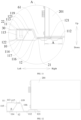
- the main portion includes: a top plate, a bottom plate, a first side plate and a second side plate.
- the top plate and the bottom plate are arranged at intervals in a height direction of the side beam.
- the first side plate and the second side plate are arranged at intervals in the width direction of the side beam.
- the first side plate is connected between the top plate and the bottom plate, the second side plate is connected between the supporting portion and the top plate, and a structure strengthening plate is connected between the top plate and the bottom plate.
- the structure strengthening plate is obliquely connected between the top plate and the bottom plate.
- the structure strengthening plate in a direction from an upper end to a lower end of the side beam, is arranged to tilt away from the accommodating groove.
- the angle between the structure strengthening plate and the bottom plate is ⁇ , and ⁇ meets the relation formula: 110° ⁇ 140°.
- the second side plate in the direction from an upper end to a lower end of the side beam, is arranged to tilt toward the accommodating groove.
- the angle between the second side plate and the structure strengthening plate is ⁇ , and ⁇ meets the relation formula: 50° ⁇ 70°.
- a height difference between a lower surface of the bottom plate and a lower surface of the supporting portion is H, and H meets the relation formula: 5 mm ⁇ H ⁇ 10 mm.
- At least part of the structure of the second body is located below the supporting portion, the structure of the second body located below the supporting portion is provided with a boss protruding toward the first body, and the boss is fixedly connected to the supporting portion.
- the second body is configured as a flat plate structure, the second body is fixedly connected to the supporting portion, and the supporting portion is provided with a boss for supporting the battery core.
- the main portion and the supporting portion are configured as an integrally formed component.
- the battery tray according to the present disclosure includes a side beam, where the side beam is the side beam for a battery tray as described above; a tray bottom plate, where the tray bottom plate has a pressurized area configured to support a battery core.
- the supporting portion is located below and supports the tray bottom plate, and an orthographic projection of the supporting portion and an orthographic projection of the pressurized area in a height direction of the battery tray have an overlapping area.
- the battery pack according to the present disclosure includes: a battery core; a battery tray, where the battery tray is a battery tray as described above; and a cover, where the cover and the battery tray jointly define an accommodating cavity configured to accommodate the battery core, and the cover is connected to the battery tray.
- the vehicle according to the present disclosure a battery pack as described above.
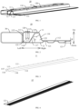
- the battery tray 100 has an accommodating groove 1000 for accommodating a battery core 201.
- the battery tray 100 includes a side frame 60, and the side frame 60 defines a mounting space 61.
- the side frame 60 may include a front beam 40, a rear beam 50 and two side beams 10.
- the two side beams 10, the front beam 40 and the rear beam 50 jointly define the mounting space 61.
- a battery pack 200 is arranged in a pattern as shown in FIG. 8
- the two side beams 10 are arranged at intervals in a left-right direction in FIG. 8
- the front beam 40 and the rear beam 50 are connected between the two side beams 10.
- the front beam 40 and the rear beam 50 are arranged at intervals in a front-rear direction of the battery pack 200. In this way, the front beam 40, the rear beam 50 and the two side beams 10 jointly define the mounting space 61. It is clear that, in other embodiments, two or more side beams 10 may be provided.
- the side beam 10 includes a first body 11 and a second body 12.
- the first body 11 includes a main portion 111 and a supporting portion 112.
- the supporting portion 112 is connected to the main portion 111, the supporting portion 112 is provided at an end of the main portion 111 close to the accommodating groove 1000, and the supporting portion 112 is configured to support the battery core 201.
- the main portion 111 is connected with the supporting portion 112 at a side close to the mounting space 61, and the supporting portion 112 extends toward the interior of the mounting space 61.
- the width direction of the side beam 10 refers to a left-right direction as shown in FIG. 2 .
- the mounting space 61 and the accommodating groove 1000 are right to the side beam 10.
- the second body 12 and the first body 11 are split workpieces, or it can be considered that the second body 12 and the first body 11 are separate members, the second body 12 and the first body 11 are not integrally formed members, the second body 12 and the first body 11 are separately processed and produced, and the second body 12 is fixed to the first body 11. That is to say, the second body 12 and the first body 11 are fixedly connected.
- the second body 12 and the first body 11 can be fixed by welding, the second body 12 and the first body 11 can be fixed by threaded connection, or the second body 12 and the first body 11 can be fixed by rivet connection and bonding.
- description is made by way of example in which the second body 12 and the first body 11 are connected by welding.
- At least part of the structure of the second body 12 is located at a side of supporting portion 112 away from the accommodating groove 1000.
- the at least part of the structure of second body 12 is located at a lower side of the supporting portion 112. That is to say, the at least part of the structure of the second body 12 is located below the supporting portion 112, or it can be considered that the at least part of the structure of the second body 12 is located at a side of the supporting portion 112 away from the battery core 201.
- the at least part of the structure of the second body 12 is located below the supporting portion 112.
- the other part of the structure of the second body 12 can be located below the main portion 111 and/or above the main portion 111 and/or at a side of the main portion 111.
- part of the structure of the second body 12 is located below the supporting portion 112
- the other part of the structure of the second body 12 is located below the main portion 111.
- the battery tray 100 may further include a tray bottom plate 20.
- the tray bottom plate 20 has a pressurized area 2011 configured to support the battery core 201. That is, a bottom wall of the accommodating groove 1000 has the pressurized area 2011.
- the pressurized area 2011 refers to an area where the orthographic projection of the tray bottom plate 20 overlaps with the orthographic projection of the battery core 201 in a height direction of the battery tray 100, when the battery core 201 is mounted on the tray bottom plate 20. Alternatively, it can be considered as a contact area between the battery core 201 and the tray bottom plate 20 when the battery core 201 is mounted on the tray bottom plate 20.
- the contact area includes an area where the battery core 201 is in direct contact or indirect contact with the tray bottom plate 20.
- the battery core 201 is in indirect contact with the tray bottom plate 20 when there is an adhesive or a cooling structure between the battery core 201 and the tray bottom plate 20, and the battery core 201 is in direct contact with the tray bottom plate 20 when there is no an additional object between the battery core 201 and the tray bottom plate 20.
- an area where the weight of the battery core 201 directly acts on the tray bottom plate 20 is the pressurized area 2011.
- the orthogonal projection of a bottom wall of the accommodating groove 1000 is the orthogonal projection of the bottom wall of accommodating groove 1000 to a plane perpendicular to the height direction of the battery tray 100.
- the orthogonal projection of the battery core 201 is the projection of the battery core 201 in a plane perpendicular to the height direction of the battery tray 100.
- the battery core 201 When the battery core 201 is mounted in the battery tray 100, the battery core 201 is located on the tray bottom plate 20 and in the pressurized area 2011 of the tray bottom plate 20.
- the tray bottom plate 20 When the battery pack 200 is arranged in a pattern as shown in FIGs. 8 and 11 , the tray bottom plate 20 is located above the supporting portion 112.
- the orthographic projection of the supporting portion 112 and the orthographic projection of the compressed area 2011 have an overlapping area, to allow the supporting portion 112 to support the battery core 201.
- the weight of the battery core 201 is loaded on the side beam 10.
- the side beam 10 bears most of the weight of the battery core 201, and the tray bottom plate 20 does not bear the weight of the battery core 201 or bears a small fraction of the weight of the battery core 201, greatly reducing the weight bearing requirement for the tray bottom plate 20 and reducing the thickness of the tray bottom plate 20.
- the tray bottom plate 20 is configured as a nonmetallic member.
- the tray bottom plate 20 is configured as an insulating member. Therefore, the tray bottom plate 20 can be made of materials with lower strength and small thickness.
- the tray bottom plate 20 may be formed of a lightweight nonmetallic composite material.
- the lightweight nonmetallic composite material can be made of a resin and glass fiber, where the resin can be epoxy resin or polyurethane, and the present disclosure is not limited thereto.
- the lightweight nonmetallic composite material can also be a composite material that is made of other resins and glass fiber and has the same function. This reduces the weight of the tray bottom plate 20, facilitates the lightweight design of the battery tray 100 and the battery pack 200, and reduces the production cost of the side beam 10, the battery tray 100, and the battery pack 200.
- the second body 12 and the first body 11 By configuring the second body 12 and the first body 11 as split workpieces, the second body 12 and the first body 11 can be produced separately, and the thickness and material of the second body 12 and the first body 11 can be adjusted separately, so that the side beam 10 meets the design requirements of the strength and weight at different positions.
- the side beam 10 of the present disclosure has reduced production cost.
- a complicated cross section is difficult to be integrally rolled.
- a side beam 10 having a complicated cross section can be formed.
- the side beam 10 bears most of the weight of the battery core 201, and the tray bottom plate 20 of the battery tray 100 bears a small fraction of the weight of the battery core 201, which reduce the strength requirement for the tray bottom plate 20, reduce the thickness of the tray bottom plate 20, and facilitate the lightweight design and the cost reduction of the battery pack 200.
- the second body 12 and the first body 11 as split workpieces, the second body 12 and the first body 11 can be produced separately, and the thickness and material of the second body 12 and the first body 11 can be adjusted separately, so that the side beam 10 meets the design requirements of the strength and weight at different positions.
- the width direction of the side beam 10 refers to the left-right direction as shown in FIG. 2 .
- a length dimension of the supporting portion 112 for supporting the battery core 201 is A, and A meets the relation formula: 30 mm ⁇ A ⁇ 100 mm.
- the orthographic projection of the supporting portion 112 and the orthographic projection of the pressurized area 2011 in the up-down direction as shown in FIG. 11 has an overlapping length of 30 mm to100 mm in the width direction of the side beam 10.
- Such an arrangement can ensure a supporting area of the supporting portion 112 to support the battery core 201, and ensure that the supporting portion 112 supports the battery core 201, and allows the supporting portion 112 to reliably support the battery core 201, to reduce the risk of vibration failure of the battery core 201, reduce the risk of vibration failure of the battery pack 200, and ensure the vibration safety of the battery pack 200.
- the main portion 111 may include: a top plate 113, a bottom plate 114, a first side plate 115 and a second side plate 116.
- the top plate 113 and the bottom plate 114 are arranged at intervals in a height direction of the side beam 10.
- the first side plate 115 and the second side plate 116 are arranged at intervals in the width direction of the side beam 10.
- the first side plate 115 is connected between the top plate 113 and the bottom plate 114.
- the first side plate 115 and the second side plate 116 are arranged at intervals.
- the second side plate 116 is located at a side of the first side plate 115 close to the accommodating groove 1000 of the battery tray 100, and the second side plate 116 is connected between the supporting portion 112 and the top plate 113.
- a lower end of the second side plate 116 is connected to the supporting portion 112, and an upper end of the second side plate 116 is connected to the top plate 113.
- the supporting portion 112 is connected to the second body 12 by welding.
- a structure strengthening plate 117 is connected between the top plate 113 and the bottom plate 114.
- the structure strengthening plate 117 is located between the first side plate 115 and the second side plate 116. As shown in FIGs. 2 and 7 , a lower end of the first side plate 115 is connected with the bottom plate 114.
- the bottom plate 114 is connected to both the second body 12 and the structure strengthening plate 117.
- the bottom plate 114 is connected to the second body 12 by welding.
- the structure strengthening plate 117 has a first connecting plate 119 at an upper end.
- the first connecting plate 119 is connected to the top plate 113, for example, the first connecting plate 119 is connected to the top plate 113 by welding.
- the structure strengthening plate 117 is spaced apart from both the first side plate 115 and the second side plate 116.
- the structure strengthening plate 117, the bottom plate 114, the first side plate 115 and the top plate 113 jointly define a first cavity 122.
- the structure strengthening plate 117, the second body 12, the second side plate 116 and the top plate 113 jointly define a second cavity 123.
- the first cavity 122 and the second cavity 123 are arranged in the width direction of the side beam 10.
- the first cavity 122 When the first cavity 122 is impacted, the first cavity 122 can absorb the impact force, which reduces the impact force transmitted to the inside of the battery pack 200, and reduces the risk of damage of the battery core 201 in the battery pack 200, thereby improving the safety of the battery pack 200 during use.
- the height direction of the side beam 10 is consistent with the height direction of the battery tray 100
- the width direction of the side beam 10 is consistent with the width direction or length direction of the battery tray 100.
- the height direction of the side beam 10 may be consistent with the height direction of the vehicle 2000
- the width direction of the side beam 10 may be consistent with the length or the width direction of the vehicle.
- the main portion 111 is provided with a rivet nut 120.
- the rivet nut 120 is provided on the top plate 113.
- the rivet nut 120 extends into the first cavity 122, and the side beam 10 and a cover 202 of the battery pack 200 are assembled by fitting a bolt to the rivet nut 120.
- the structure strengthening plate 117 is obliquely connected between the top plate 113 and the bottom plate 114, and the structure strengthening plate 117 is obliquely supported between the top plate 113 and the bottom plate 114, whereby the structural strength and rigidity of the side beam 10 are further increased, the structural stability of the side beam 10 is improved, and the risk of deformation of the side beam 10 is further reduced, to extend the service life of the side beam 10 and the battery tray 100.
- the structure strengthening plate 117 when the side beam 10 is arranged in a pattern as shown in FIG. 2 , in a direction from an upper end to a lower end of the side beam 10, the structure strengthening plate 117 is arranged to tilt away from the accommodating groove 1000, or it can be considered that the structure strengthening plate 117 is arranged to tilt away from the second side plate 116, or it can be considered that the structure strengthening plate 117 is arranged to tilt away from the mounting space 61 of the battery tray 100. Alternatively, it can be considered that in an up-down direction of the battery tray 100, the structure strengthening plate 117 is arranged to extend obliquely away from the mounting space 61.
- the structural strength and rigidity of the side beam 10 are further increased, and the stability of the side beam 10 is further improved, thereby further improving the capability of the side beam 10 to support the battery core 201, and further reducing the risk of deformation of the side beam 10.
- the angle between the structure strengthening plate 117 and the bottom plate 114 is ⁇ , and ⁇ meets the relation formula: 110° ⁇ 140°.
- ⁇ is 120°.
- the second side plate 116 in the direction from the upper end to the lower end of the side beam 10, is arranged to tilt toward the accommodating groove 1000.
- the structure strengthening plate 116 is arranged to tilt away from the first side plate 115.
- the angle between the second side plate 116 and the structure strengthening plate 117 is ⁇ , and ⁇ meets the relation formula: 50° ⁇ 70°.
- ⁇ is 60°.
- the cross-sectional shape of the first cavity 122 and the cross-sectional shape of the second cavity 123 are both triangular or trapezoidal. Through such an arrangement, the structural stability of the side beam 10 is increased, and the risk of deformation of the side beam 10 is further reduced.
- the cross-sectional shape of the second cavity 123 is triangular. That is, the shape of a cross section of the second cavity 123 that is perpendicular to a length direction of the side beam 10 is triangular, further, isosceles triangle or equilateral triangle.
- the second body 12 serves as a bottom wall of the triangle.
- the angle between the second body 12 and the structure strengthening plate 117 serves as a base angle of the triangle.
- the base angle is ⁇ 1 that meets the relation formula: 50° ⁇ 1 ⁇ 70°.
- ⁇ 1 is 60°.
- the vertex angle of the triangle is ⁇ that meets the relation formula: 50° ⁇ 70°.
- ⁇ is 60°.
- the cross-sectional shape of the second cavity 123 is arranged to be an equilateral triangle.
- the cross-sectional shape of the second cavity 123 is arranged to be a trapezoid. That is, the shape of a cross section of the second cavity 123 that is perpendicular to the length direction of the side beam 10 is trapezoidal.
- the second body 12 serves as a bottom wall of the trapezoid
- the angle between the second body 12 and the structure strengthening plate 117 serves as a base angle of the trapezoidal shape of the second cavity 123.
- the base angle is ⁇ 1 that meets the relation formula: 50° ⁇ 1 ⁇ 70°. For example, ⁇ 1 is 60°.
- the cross-sectional shape of the first cavity 122 is trapezoidal. That is, the shape of a cross section of the first cavity 122 that is perpendicular to the length direction of the side beam 10 is trapezoidal.
- the bottom plate 114 serves as a top wall of the trapezoidal shape of the first cavity 122
- the top plate 113 serves as a bottom wall of the trapezoidal shape of the first cavity 122.
- a height difference between a lower surface of the bottom plate 114 and a lower surface of the supporting portion 112 is H, and H meets the relation formula: 5 mm ⁇ H ⁇ 10 mm.
- H is 8 mm.
- the tray bottom plate 20 is provided on an upper surface of the supporting portion 112, and the supporting portion 112 supports the tray bottom plate 20.
- a thermal insulation layer is provided to a lower surface of the tray bottom plate 20. The thermal insulation layer serves for heat preservation of the battery pack 200.
- the thermal insulation layer is located between two opposite side beams 10.
- a space in which the thermal insulation layer is provided can be formed below the tray bottom plate 20. Accordingly, the insulation layer is ensured to have an appropriate thickness, so as to well thermally insulate the battery pack 200, and a lower surface of the thermal insulation layer is avoided to protruding out of the battery tray 100, so that the bottom of the battery tray 100 becomes more flat.
- At least part of the structure of the second body 12 is located below the supporting portion 112.
- a structure of the second body 12 located below the supporting portion 112 is connected to the main portion 111 and/or the supporting portion 112. Further, as shown in FIGs. 2 and 7 , when the side beam 10 is arranged in a pattern as shown in FIG. 2 , the whole structure of the second body 12 is located below the first body 11, part of the structure of the second body 12 is located below the supporting portion 112, and the other part of the structure of the second body 12 is located below the main portion 111.
- the second body 12 located below the main portion 111 is connected to the bottom plate 114 by welding, and the second body 12 located below the supporting portion 112 is connected to the supporting portion 112 by welding.
- the second body 12 has a structuring strengthening performance. Through such an arrangement, the structural strength and rigidity of the side beam 10 are further increased, and the risk of deformation of the side beam 10 is reduced.
- the structure of the second body 12 is located below the supporting portion 112.
- the structure of the second body 12 located below the supporting portion 112 is provided with a boss 121 protruding toward the first body 11, and the boss 121 is fixedly connected to the supporting portion 112.
- the boss 121 is arranged corresponding to the supporting portion 112, and the boss 121 is connected to the supporting portion 112 by welding.
- the second body 12 protrudes toward the supporting portion 112 to form the boss 121.
- the second body 12 can be formed by rolling.
- the structure of the second body 12 located below the supporting portion 112 is provided with multiple bosses 121, the multiple bosses 121 are arranged in the width direction of the side beam 10 in sequence, and at least one boss 121 of the multiple bosses 121 is located below the pressurized area 2011.
- Such an arrangement enables the boss 121 to support the battery core 201, thereby further improving the weight bearing capacity of the side beam 10 and reducing the risk of deformation of the supporting portion 112.
- a protruding structure is provided at a surface of the second body 12 close to the supporting portion 112 to form the boss 121.
- the boss 121 is internally provided with a weight reducing cavity 124.
- the second body 12 can be formed by extruding, and the boss 121 is located below the supporting portion 112.
- the second body 12 configured as a flat plate structure.
- the structure of the second body 12 is simplified, the manufacturing of the second body 12 is promoted, the production efficiency of the second body 12 is improved, and the first body 11 is facilitated to be formed by rolling.
- the second body 12 is fixedly connected to the supporting portion 112.
- the supporting portion 112 is provided with the boss 121 configured to support the battery core 201.
- the orthographic projection of the boss 121 and the orthographic projection of the battery core 201 have an overlapping area.
- the boss 121 is located below and support the battery core 201, and the boss 121 can support the battery core 201.
- the boss 121 can support the battery core 201, and the strength of supporting battery core 201 is increased, whereby the battery core 201 is reliably supported, and the side beam 10 meets the requirement of supporting the battery core 201.
- the side beam 10 is connected with a lifting lug structure 30, and the side beam 10 and the lifting lug structure 30 can be connected by welding.
- the lifting lug structure 30 is provided with a mounting hole 31, and the lifting lug structure 30 is mounted on the vehicle 2000 by a fastener (such as a bolt), so as to achieve the purpose of mounting the battery pack 200 on the vehicle 2000.
- the side beam 10 according to the first embodiment and the side beam 10 according to the second embodiment differ in that the specific structures of the boss 121 are different, and the specific structures of the lifting lug structure 30 are different.
- the height of the supporting portion 112 is lower than the height of an upper surface of the main portion 111.
- the main portion 111 and the supporting portion 112 are configured as an integrally formed component.
- the first body 11 can be configured as an integrally formed component, and the structural strength and rigidity of the first body 11 are increased, to further improve the weight bearing capacity of the side beam 10.
- the first body 11 and the second body 12 are connected by welding through at least one row of solder joint set.
- Each row of solder joint set includes multiple solder joints, and the distance between any two adjacent solder joints in each row of solder joint set is D that meets the relation formula: 40 mm ⁇ D ⁇ 60 mm.
- the first body 11 and the second body 12 are connected by laser welding. Too dense solder joints will lead to the deformation of the first body 11 and the second body 12, and too few solder joints will lead to insufficient assembly strength of the first body 11 and the second body 12.
- the deformation of the first body 11 and the second body 12 can be avoided, and the assembly strength between the first body 11 and the second body 12 can also be ensured, to avoid the separation of the first body 11 from the second body 12.
- the first body 11 and the second body 12 can be made of an aluminum material, or the first body 11 and the second body 12 can also be made of a steel material, which is not limited in the present disclosure.
- the first body 11 and the second body 12 can also be made of other metal materials that have the same function as steel.
- the first body 11 and the second body 12 are both made of a steel material.
- the first body 11 and the second body 12 can be rolled with the steel material, or the first body 11 and the second body 12 can also be extruded with the steel material.
- the first body 11 and the second body 12 made of a steel material can withstand a high temperature of 1500°C or more, which ensures the integrity of the side beam 10 upon thermal runaway of the battery core 201.
- the battery tray 100 includes: a side beam 10 and a tray bottom plate 20.
- the side beam 10 is a side beam 10 according to the above embodiment
- the tray bottom plate 20 is a tray bottom plate 20 according to the above embodiment.
- the battery tray 100 includes a side frame 60, and the side frame 60 defines a mounting space 61.
- the side frame 60 includes a side beam 10, and the tray bottom plate 20 is mounted in the mounting space 61.
- the tray bottom plate 20 has a pressurized area 2011 configured to support the battery core 201.
- the supporting portion 112 is located below and support the tray bottom plate 20.
- the orthographic projection of the supporting portion 112 and the orthographic projection of the compressed area 2011 have an overlapping area, to allow the supporting portion 112 to support the battery core 201.
- the weight of the battery core 201 is loaded on the side beam 10.
- the side beam 10 bears most of the weight of the battery core 201
- the tray bottom plate 20 bears a small fraction of the weight of the battery core 201, greatly reducing the weight bearing requirement for the tray bottom plate 20. Therefore, the tray bottom plate 20 can be made of materials with lower strength and small thickness. This reduces the weight of the tray bottom plate 20, facilitates the lightweight design of the battery tray 100 and the battery pack 200, and reduces the production cost of the side beam 10, the battery tray 100, and the battery pack 200.
- the width direction of the battery tray 100 may be consistent with the width direction of the vehicle, and the length direction of the battery tray 100 can be consistent with the length direction of the vehicle. It is clear that the width direction of the battery tray 100 may be consistent with the length direction of the vehicle and the length direction of the battery tray 100 may be consistent with the width direction of the vehicle.
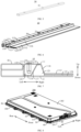
- the battery pack 200 includes a battery core 201, a battery tray 100 and a cover 202.
- the battery tray 100 is a battery tray 100 according to the above embodiment.
- the cover 202 and the battery tray 100 jointly define an accommodating cavity for accommodating the battery core 201, and the cover 202 is connected to the battery tray 100.
- the cover 202, the side frame 60 and the tray bottom plate 20 jointly define an accommodating cavity for accommodating the battery core 201.
- the cover 202 covers the accommodating groove 1000 of the battery tray 100 to form the accommodating cavity.
- the battery core 201 is accommodated in the accommodating cavity.
- the cover 202 is mounted to the side frame 60 by fitting a bolt to the rivet nut 120. Further, a seal (such as a sealing ring) is sandwiched at a joint between the cover 202 and the side frame 60. The gap between the cover 202 and the side frame 60 is sealed by the seal, to seal the accommodating cavity, and ensure the leak tightness of the battery tray 200.
- a seal such as a sealing ring
- the battery pack 200 further includes: a press plate.
- the press plate is configured as a closed ring structure.
- the cover 202 and the seal are sandwiched between the press plate and the side frame 60.
- a bolt extends through the press plate, the cover 202 and the seal and is connected to the rivet nut 120, to assemble the press plate, the cover 202, the seal and the side frame 60 together.
- the press plate allows the whole seal to be uniformly pressed, and ensures the reliable sealing of the accommodating cavity.
- the tray bottom plate 20 includes a bottom plate body 21 and an extension portion 22.
- the bottom plate body 21 defines an accommodating groove 1000 for accommodating the battery core 201 or a battery module. In the present disclosure, description is made by way of example in which the accommodating groove 1000 accommodates the battery core 201.
- a bottom wall of the bottom plate body 21 has a pressurized area 2011 configured to support the battery core 201.
- the extension portion 22 is arranged to extend along a peripheral edge of the bottom plate body 21. Further, the extension portion 22 is configured as a circular structure. Particularly, the extension portion 22 is configured as a closed ring structure.
- the bottom plate body 21 is mounted in the mounting space 61, and the extension portion 22 is located outside the mounting space 61. In the height direction of the battery tray 100, the extension portion 22 is located above the side frame 60 and arranged on the side frame 60.
- the cover 202 is covered at an open end of the accommodating groove 1000 to define the accommodating cavity.
- the extension portion 22 is sandwiched between the cover 202 and the side frame 60.
- the bolt extends through the cover body 202.
- the cover 202, the tray bottom plate 20 and the side frame 60 are assembled together by the extension portion 12 and the side frame 20.
- a seal (such as a sealing ring) is sandwiched between the extension portion 22 and the cover 202, and the seal can seal the accommodating cavity.
- the cover 202 and the tray bottom plate 20 define a sealed insulating cavity (i.e. the accommodating cavity).
- the battery pack 200 further includes: a press plate 203.
- the press plate 203 is configured as a closed ring structure.
- the cover 202, the seal and the extension portion 22 are sandwiched between the press plate 203 and the side frame 60.
- a bolt extends through the press plate 203, the cover 202, the extension portion 22 and the side frame 60 to assemble the press plate 203, the cover 202, the tray bottom plate 20 and the side frame 60 together.
- the press plate 203 allows the whole seal to be uniformly pressed, and ensures the reliable sealing of the accommodating cavity.
- the vehicle 2000 includes a battery pack 200 according to above embodiment.
- the battery pack 200 is mounted on the vehicle 2000 to provide electric energy for the vehicle 2000.
- the side beam 10 bears most of the weight of the battery core 201
- the tray bottom plate 20 of the battery tray 100 bears a small fraction of the weight of the battery core 201, which reduce the strength requirement for the tray bottom plate 20, reduce the thickness of the tray bottom plate 20, facilitate the lightweight design and the cost reduction of the battery pack 200, thereby facilitating the lightweight design and the cost reduction of the vehicle 2000.
- the second body 12 and the first body 11 can be produced separately, and the thickness and material of the second body 12 and the first body 11 can be adjusted separately, so that the side beam 10 meets the design requirements of the strength and weight at different positions.
Landscapes
- Chemical & Material Sciences (AREA)
- Chemical Kinetics & Catalysis (AREA)
- Electrochemistry (AREA)
- General Chemical & Material Sciences (AREA)
- Engineering & Computer Science (AREA)
- Aviation & Aerospace Engineering (AREA)
- Mechanical Engineering (AREA)
- Battery Mounting, Suspending (AREA)
- Arrangement Or Mounting Of Propulsion Units For Vehicles (AREA)
Applications Claiming Priority (2)
| Application Number | Priority Date | Filing Date | Title |
|---|---|---|---|
| CN202220554010.XU CN217158427U (zh) | 2022-03-14 | 2022-03-14 | 用于电池托盘的边梁、电池托盘、电池包以及车辆 |
| PCT/CN2023/081345 WO2023174270A1 (zh) | 2022-03-14 | 2023-03-14 | 用于电池托盘的边梁、电池托盘、电池包以及车辆 |
Publications (2)
| Publication Number | Publication Date |
|---|---|
| EP4435950A1 true EP4435950A1 (de) | 2024-09-25 |
| EP4435950A4 EP4435950A4 (de) | 2025-03-19 |
Family
ID=82693485
Family Applications (1)
| Application Number | Title | Priority Date | Filing Date |
|---|---|---|---|
| EP23769772.7A Pending EP4435950A4 (de) | 2022-03-14 | 2023-03-14 | Randträger für batteriefach, batteriefach, batteriepack und fahrzeug |
Country Status (6)
| Country | Link |
|---|---|
| US (1) | US20240347828A1 (de) |
| EP (1) | EP4435950A4 (de) |
| JP (1) | JP7821287B2 (de) |
| KR (1) | KR20240110045A (de) |
| CN (1) | CN217158427U (de) |
| WO (1) | WO2023174270A1 (de) |
Families Citing this family (6)
| Publication number | Priority date | Publication date | Assignee | Title |
|---|---|---|---|---|
| CN217158427U (zh) * | 2022-03-14 | 2022-08-09 | 比亚迪股份有限公司 | 用于电池托盘的边梁、电池托盘、电池包以及车辆 |
| CN115579562A (zh) * | 2022-10-20 | 2023-01-06 | 江苏天钧精密技术有限公司 | 一种储能轻量化结构电池箱体 |
| JP2025538900A (ja) * | 2023-03-31 | 2025-12-02 | 恵州億緯▲リ▼能股▲フン▼有限公司 | 電池取付筐と電池パケージ |
| JP7831396B2 (ja) * | 2023-05-17 | 2026-03-17 | トヨタ自動車株式会社 | 電池ケースのケース側壁 |
| ES3056641T3 (en) * | 2023-11-13 | 2026-02-23 | Benteler Automobiltechnik Gmbh | Battery support |
| CN120473629A (zh) * | 2024-09-14 | 2025-08-12 | 比亚迪股份有限公司 | 电池托盘的边梁、电池托盘、电池系统及用电设备 |
Family Cites Families (13)
| Publication number | Priority date | Publication date | Assignee | Title |
|---|---|---|---|---|
| JP2010284984A (ja) * | 2009-06-09 | 2010-12-24 | Fuji Heavy Ind Ltd | 車両用バッテリ搭載構造 |
| JP6020958B2 (ja) * | 2012-07-13 | 2016-11-02 | 三菱自動車工業株式会社 | 電池パックトレー |
| JP5967477B2 (ja) * | 2012-07-13 | 2016-08-10 | 三菱自動車工業株式会社 | 電池パック |
| JP2018202887A (ja) * | 2017-05-30 | 2018-12-27 | 本田技研工業株式会社 | 車両の下部構造体 |
| US10773582B2 (en) * | 2018-02-19 | 2020-09-15 | Dura Operating, Llc | Automobile vehicle battery tray with side impact rails |
| JP6689911B2 (ja) * | 2018-05-25 | 2020-04-28 | 本田技研工業株式会社 | 車体下部構造体 |
| WO2020000090A1 (en) * | 2018-06-25 | 2020-01-02 | Magna International Inc. | Battery frame |
| CN210805843U (zh) * | 2019-08-05 | 2020-06-19 | 比亚迪股份有限公司 | 电池托盘、动力电池包及车辆 |
| CN112448086B (zh) * | 2019-08-16 | 2022-04-15 | 比亚迪股份有限公司 | 电池托盘、电池包及车辆 |
| WO2021157648A1 (ja) * | 2020-02-04 | 2021-08-12 | 日本製鉄株式会社 | トレイ及びトレイの製造方法 |
| US12202324B2 (en) * | 2020-04-27 | 2025-01-21 | Hyundai Motor Company | Battery case for vehicle |
| CN213936400U (zh) * | 2020-06-16 | 2021-08-10 | 苏州亿创特智能制造有限公司 | 一种辊压型材、电池包骨架及电池包 |
| CN217158427U (zh) * | 2022-03-14 | 2022-08-09 | 比亚迪股份有限公司 | 用于电池托盘的边梁、电池托盘、电池包以及车辆 |
-
2022
- 2022-03-14 CN CN202220554010.XU patent/CN217158427U/zh active Active
-
2023
- 2023-03-14 JP JP2024535619A patent/JP7821287B2/ja active Active
- 2023-03-14 EP EP23769772.7A patent/EP4435950A4/de active Pending
- 2023-03-14 WO PCT/CN2023/081345 patent/WO2023174270A1/zh not_active Ceased
- 2023-03-14 KR KR1020247020421A patent/KR20240110045A/ko active Pending
-
2024
- 2024-06-26 US US18/755,287 patent/US20240347828A1/en active Pending
Also Published As
| Publication number | Publication date |
|---|---|
| JP7821287B2 (ja) | 2026-02-26 |
| KR20240110045A (ko) | 2024-07-12 |
| CN217158427U (zh) | 2022-08-09 |
| US20240347828A1 (en) | 2024-10-17 |
| EP4435950A4 (de) | 2025-03-19 |
| JP2025505915A (ja) | 2025-03-05 |
| WO2023174270A1 (zh) | 2023-09-21 |
Similar Documents
| Publication | Publication Date | Title |
|---|---|---|
| EP4435950A1 (de) | Randträger für batteriefach, batteriefach, batteriepack und fahrzeug | |
| US20240347837A1 (en) | Edge beam for battery tray, battery tray, battery pack and vehicle | |
| EP4148874B1 (de) | Batteriekasten | |
| CN217134566U (zh) | 电池托盘、电池包以及车辆 | |
| US20240356131A1 (en) | Battery tray, battery pack, and vehicle | |
| US20240356145A1 (en) | Battery pack and vehicle | |
| CN217158461U (zh) | 电池托盘的边框组件、电池托盘、电池包以及车辆 | |
| CN217387409U (zh) | 电池托盘、电池包以及车辆 | |
| US10833303B2 (en) | Composite end plate and battery module | |
| CN217158434U (zh) | 电池托盘、电池包以及车辆 | |
| US20240363943A1 (en) | Edge beam used for battery tray, battery tray, battery pack, and vehicle | |
| CN217788662U (zh) | 电池包以及车辆 | |
| CN217788646U (zh) | 托盘组件、动力电池包和车辆 | |
| CN220042023U (zh) | 电池包及用电装置 | |
| CN217158460U (zh) | 电池托盘的边梁、电池托盘、电池包以及车辆 | |
| CN117832724B (zh) | 电池包及车辆 | |
| CN217656008U (zh) | 电池包的边梁和具有其的电池包 | |
| JP7853425B2 (ja) | 電池トレイ用エッジビーム、電池トレイ、電池パック及び車両 | |
| CN121076368B (zh) | 一种电池包壳体、电池包以及用电设备 |
Legal Events
| Date | Code | Title | Description |
|---|---|---|---|
| STAA | Information on the status of an ep patent application or granted ep patent |
Free format text: STATUS: THE INTERNATIONAL PUBLICATION HAS BEEN MADE |
|
| PUAI | Public reference made under article 153(3) epc to a published international application that has entered the european phase |
Free format text: ORIGINAL CODE: 0009012 |
|
| STAA | Information on the status of an ep patent application or granted ep patent |
Free format text: STATUS: REQUEST FOR EXAMINATION WAS MADE |
|
| 17P | Request for examination filed |
Effective date: 20240619 |
|
| AK | Designated contracting states |
Kind code of ref document: A1 Designated state(s): AL AT BE BG CH CY CZ DE DK EE ES FI FR GB GR HR HU IE IS IT LI LT LU LV MC ME MK MT NL NO PL PT RO RS SE SI SK SM TR |
|
| A4 | Supplementary search report drawn up and despatched |
Effective date: 20250214 |
|
| RIC1 | Information provided on ipc code assigned before grant |
Ipc: H01M 50/249 20210101ALI20250210BHEP Ipc: H01M 50/244 20210101ALI20250210BHEP Ipc: H01M 50/233 20210101ALI20250210BHEP Ipc: H01M 50/22 20210101AFI20250210BHEP |
|
| DAV | Request for validation of the european patent (deleted) | ||
| DAX | Request for extension of the european patent (deleted) |