EP4435459B1 - Shimspulen für ein kompaktes mrt-gradientensystem auf basis von mehrschichtigen flexiblen leiterplatten und anordnungsschema für leiterschichten - Google Patents
Shimspulen für ein kompaktes mrt-gradientensystem auf basis von mehrschichtigen flexiblen leiterplatten und anordnungsschema für leiterschichten Download PDFInfo
- Publication number
- EP4435459B1 EP4435459B1 EP23315058.0A EP23315058A EP4435459B1 EP 4435459 B1 EP4435459 B1 EP 4435459B1 EP 23315058 A EP23315058 A EP 23315058A EP 4435459 B1 EP4435459 B1 EP 4435459B1
- Authority
- EP
- European Patent Office
- Prior art keywords
- coils
- assembly
- printed circuit
- shim
- flexible printed
- Prior art date
- Legal status (The legal status is an assumption and is not a legal conclusion. Google has not performed a legal analysis and makes no representation as to the accuracy of the status listed.)
- Active
Links
Images


Classifications
-
- G—PHYSICS
- G01—MEASURING; TESTING
- G01R—MEASURING ELECTRIC VARIABLES; MEASURING MAGNETIC VARIABLES
- G01R33/00—Arrangements or instruments for measuring magnetic variables
- G01R33/20—Arrangements or instruments for measuring magnetic variables involving magnetic resonance
- G01R33/28—Details of apparatus provided for in groups G01R33/44 - G01R33/64
- G01R33/38—Systems for generation, homogenisation or stabilisation of the main or gradient magnetic field
- G01R33/385—Systems for generation, homogenisation or stabilisation of the main or gradient magnetic field using gradient magnetic field coils
-
- G—PHYSICS
- G01—MEASURING; TESTING
- G01R—MEASURING ELECTRIC VARIABLES; MEASURING MAGNETIC VARIABLES
- G01R33/00—Arrangements or instruments for measuring magnetic variables
- G01R33/0052—Manufacturing aspects; Manufacturing of single devices, i.e. of semiconductor magnetic sensor chips
-
- G—PHYSICS
- G01—MEASURING; TESTING
- G01R—MEASURING ELECTRIC VARIABLES; MEASURING MAGNETIC VARIABLES
- G01R33/00—Arrangements or instruments for measuring magnetic variables
- G01R33/007—Environmental aspects, e.g. temperature variations, radiation, stray fields
- G01R33/0076—Protection, e.g. with housings against stray fields
-
- G—PHYSICS
- G01—MEASURING; TESTING
- G01R—MEASURING ELECTRIC VARIABLES; MEASURING MAGNETIC VARIABLES
- G01R33/00—Arrangements or instruments for measuring magnetic variables
- G01R33/20—Arrangements or instruments for measuring magnetic variables involving magnetic resonance
- G01R33/28—Details of apparatus provided for in groups G01R33/44 - G01R33/64
- G01R33/38—Systems for generation, homogenisation or stabilisation of the main or gradient magnetic field
- G01R33/385—Systems for generation, homogenisation or stabilisation of the main or gradient magnetic field using gradient magnetic field coils
- G01R33/3858—Manufacture and installation of gradient coils, means for providing mechanical support to parts of the gradient-coil assembly
-
- G—PHYSICS
- G01—MEASURING; TESTING
- G01R—MEASURING ELECTRIC VARIABLES; MEASURING MAGNETIC VARIABLES
- G01R33/00—Arrangements or instruments for measuring magnetic variables
- G01R33/20—Arrangements or instruments for measuring magnetic variables involving magnetic resonance
- G01R33/28—Details of apparatus provided for in groups G01R33/44 - G01R33/64
- G01R33/38—Systems for generation, homogenisation or stabilisation of the main or gradient magnetic field
- G01R33/387—Compensation of inhomogeneities
- G01R33/3875—Compensation of inhomogeneities using correction coil assemblies, e.g. active shimming
-
- H—ELECTRICITY
- H01—ELECTRIC ELEMENTS
- H01F—MAGNETS; INDUCTANCES; TRANSFORMERS; SELECTION OF MATERIALS FOR THEIR MAGNETIC PROPERTIES
- H01F27/00—Details of transformers or inductances, in general
- H01F27/08—Cooling; Ventilating
- H01F27/10—Liquid cooling
-
- H—ELECTRICITY
- H01—ELECTRIC ELEMENTS
- H01F—MAGNETS; INDUCTANCES; TRANSFORMERS; SELECTION OF MATERIALS FOR THEIR MAGNETIC PROPERTIES
- H01F27/00—Details of transformers or inductances, in general
- H01F27/08—Cooling; Ventilating
- H01F27/22—Cooling by heat conduction through solid or powdered fillings
-
- H—ELECTRICITY
- H01—ELECTRIC ELEMENTS
- H01F—MAGNETS; INDUCTANCES; TRANSFORMERS; SELECTION OF MATERIALS FOR THEIR MAGNETIC PROPERTIES
- H01F41/00—Apparatus or processes specially adapted for manufacturing or assembling magnets, inductances or transformers; Apparatus or processes specially adapted for manufacturing materials characterised by their magnetic properties
- H01F41/02—Apparatus or processes specially adapted for manufacturing or assembling magnets, inductances or transformers; Apparatus or processes specially adapted for manufacturing materials characterised by their magnetic properties for manufacturing cores, coils, or magnets
- H01F41/04—Apparatus or processes specially adapted for manufacturing or assembling magnets, inductances or transformers; Apparatus or processes specially adapted for manufacturing materials characterised by their magnetic properties for manufacturing cores, coils, or magnets for manufacturing coils
-
- H—ELECTRICITY
- H01—ELECTRIC ELEMENTS
- H01F—MAGNETS; INDUCTANCES; TRANSFORMERS; SELECTION OF MATERIALS FOR THEIR MAGNETIC PROPERTIES
- H01F41/00—Apparatus or processes specially adapted for manufacturing or assembling magnets, inductances or transformers; Apparatus or processes specially adapted for manufacturing materials characterised by their magnetic properties
- H01F41/02—Apparatus or processes specially adapted for manufacturing or assembling magnets, inductances or transformers; Apparatus or processes specially adapted for manufacturing materials characterised by their magnetic properties for manufacturing cores, coils, or magnets
- H01F41/04—Apparatus or processes specially adapted for manufacturing or assembling magnets, inductances or transformers; Apparatus or processes specially adapted for manufacturing materials characterised by their magnetic properties for manufacturing cores, coils, or magnets for manufacturing coils
- H01F41/041—Printed circuit coils
-
- H—ELECTRICITY
- H01—ELECTRIC ELEMENTS
- H01F—MAGNETS; INDUCTANCES; TRANSFORMERS; SELECTION OF MATERIALS FOR THEIR MAGNETIC PROPERTIES
- H01F5/00—Coils
- H01F5/003—Printed circuit coils
-
- H—ELECTRICITY
- H01—ELECTRIC ELEMENTS
- H01F—MAGNETS; INDUCTANCES; TRANSFORMERS; SELECTION OF MATERIALS FOR THEIR MAGNETIC PROPERTIES
- H01F5/00—Coils
- H01F5/04—Arrangements of electric connections to coils, e.g. leads
-
- G—PHYSICS
- G01—MEASURING; TESTING
- G01R—MEASURING ELECTRIC VARIABLES; MEASURING MAGNETIC VARIABLES
- G01R33/00—Arrangements or instruments for measuring magnetic variables
- G01R33/20—Arrangements or instruments for measuring magnetic variables involving magnetic resonance
- G01R33/28—Details of apparatus provided for in groups G01R33/44 - G01R33/64
- G01R33/38—Systems for generation, homogenisation or stabilisation of the main or gradient magnetic field
- G01R33/385—Systems for generation, homogenisation or stabilisation of the main or gradient magnetic field using gradient magnetic field coils
- G01R33/3856—Means for cooling the gradient coils or thermal shielding of the gradient coils
Definitions
- the present invention relates to a combined gradient coil and shim coil assembly for use in MR-devices as defined in claim 1, comprising
- the present invention relates to the field of magnetic resonance analysis of sample materials and, more specifically, to the nuclear spin polarization of samples for analysis using magnetic resonance measurement techniques.
- Nuclear magnetic resonance (NMR) is a phenomenon in which certain atomic nuclei become magnetically polarized in proportion to an applied magnetic field and, as a result, will absorb and re-emit electromagnetic radiation. It serves as the basis for certain measurement techniques, including magnetic resonance imaging (MRI) and NMR spectroscopy.
- MRI magnetic resonance imaging
- Nuclear magnetic resonance spectroscopy is a powerful tool in instrumental chemical analysis. In NMR experiments, a sample is exposed to a strong static magnetic field which interacts with spins of nuclei contained in the sample.
- the sample's reaction depends on the environment of the nuclei in the sample, in particular bonding electrons. Accordingly, information about the chemical structure of the sample can be obtained by analysing the RF signals measured.
- NMR nuclear magnetic resonance
- EPR electron paramagnetic resonance
- gradient coils which are usually designed as solenoid and saddle coils and are part of a hollow cylindrical assembly - the so-called gradient tube or gradient system.
- ohmic losses of up to several kW occur in these coils, which must be dissipated via a suitable cooling concept.
- the quality of the imaging depends largely on the homogeneity of the static magnetic field, which is also negatively affected by the presence of objects in the sample volume. Inherent components of the gradient tube are therefore also a large number of so-called shim coils, which compensate for the disturbing field orders and thus improve the homogeneity.
- the outer diameter Ra of the gradient tube is limited upward by the bore diameter, while the inner diameter Ri is limited downward by the space requirements of the high-frequency transmit/receive coils.
- wire coils with variable pitch or arrangements of several wire coils are usually required.
- the coils, made of enameled copper wire, are complex and delicate to manufacture.
- Frame coils must also be bent to the radius of curvature of the surface in question before application. During application, exact positioning of the coils in the range of a few tenths of a millimeter is important, otherwise deviations from the calculated field geometry are to be expected.
- WO 03/093853 A1 discloses a gradient coil system for a magnetic resonance apparatus having gradient coils, shim coils and at least one cooling tube for cooling the gradient coils using a coolant flowing through the cooling tube.
- the cooling tube is formed of a flexible thermoplastic material, augmented with a filler, and has a thermal conductivity greater than 0.5 W/mK.
- Another aspect of the present invention is the removal of heat generated during operation. Due to the electrical current in the gradient coils and in the shim coils, a lot of heat can be dissipated which can only be removed by an active cooling. According to the state of the art (see f.e. Reference [1] cited above), this is realized by plastic or copper heat exchangers, which are first brought into contact with the respective coils in the best possible way. Subsequently, coils and heat exchangers are provided with a chill casting to achieve the necessary mechanical stability. Said chill casting is generally composed of a liquid reaction resin enriched with filler having particularly high thermal conductivity.
- US 2016/0054407 A1 discloses an arrangement of active shim coils inside MRI systems.
- resistive shims are located inside the gradient coil assembly.
- the sets of saddle-shape shims are preferably constructed on a flexible printed circuit board. Neither a cooling section in the coil assembly nor a heat conducting backfilling with a thermal conductive resin are foreshadowed in Reference [4].
- Reference [5] discloses a gradient coil unit and a shim coil unit comprising a plurality of shim coils which are applied on a flexible PCB is wound on the outer circumferential surface of the gradient coil unit.
- the coil assembly is designed for clinical systems with a large inner bore of at least 50cm.
- the shim coils can be applied on both sides of the flexible printed-circuit boards and interconnected by crossing jumpers.
- the inserted PCB foils are only slightly bent here, since the diameter of the bore is relatively large.
- the different coils are separated by resin tape layers or foils which are wound about the outer circumferential surface of the shim coils for the purpose of protection and insulation. However, no thermal conductivity is mentioned.
- the intermediate insulation foil layers are not efficient for transporting heat, which is generated by the coils.
- the continuous addition of resin during the winding process i.e. while the wire and tape insulation is wound on the bobbin, is commonly referred to as wet winding.
- Dosage of the resin, adjusting the viscosity is delicate, as low viscosity resin will flow quickly and drip down while high viscosity may lead to crevices that are not filled and may develop dielectric issues (not passing high voltage testing, due to insulation breakdown). More resin than necessary is used which is problematic from the waste point of view. Furthermore the entire process is open and thus prone to pollution with dust particles.
- the present invention proposes a way to substantially overcome one or more disadvantages and trade-offs of the above discussed existing prior art devices.
- One major object of the present invention is to provide a particularly compact combined gradient and shim coil assembly with an efficient cooling system allowing a precise positioning of the coils and a time-saving manufacturing.
- the basic idea underlying the present invention was to develop a combined gradient coil and shim coil assembly for use in MR-devices as defined above, which is using flexible shim coils that allow a very compact spatial arrangement.
- the combined coil assembly together with the cooling tube assembly are encapsulated by conjoint backfilling with a heat conductive filler.
- a vacuum casting technique is applied.
- the right vacuum casting technique ensures perfect filling of all crevices, usage of the exact amount and takes place in a hermetically sealed system preventing any pollution and making insulation issues highly unlikely to happen.
- the gradient coil and shim coil assembly is preferably designed for pre-clinical MRI systems, which are used for small animals or for micro-imaging applications.
- the inner diameter Ri of the assembly is preferably between 1cm and 20cm.
- the spacer allows calibrating a defined gap between the foils to ensure that during the casting process the resin can flow. Thereby, an optimal thermal conductivity between the foil and so an optimal cooling of the foils can be guaranteed.
- the helix shape ensures that the resin flow will cover the full surface of the foil while maintaining low pressure drop for the resin.
- the thickness of the copper layer is between 35 ⁇ m to 500 ⁇ m. Due to the production as a whole, the individual coils have a fixed spatial reference to each other, so that the carrier only has to be aligned once as a whole during assembly, preferably with the aid of reference holes. Positioning errors are thus virtually eliminated.
- the coil carrier is wound onto the cylindrical body of the gradient tube as a finished component; the costly manufacture of wire coils is eliminated altogether.
- profiles filaments or other flexible profiles of the desired thickness
- the coil interconnection is preferably realized by selecting a two-sided layout.
- the carrier allows one copper layer each on the top and bottom side.
- the supply lines of one coil group can be routed between the coils of the other side by appropriate placement of the coil groups and setting of vias, so that four conductor coil circuits can effectively be realized (two coil layers and two supply or connection layers).
- a cooling unit is arranged on the outer circumference of the gradient coils.
- the cooling unit comprises a plurality of parallel or meandering arranged tubes or for conducting a refrigerating liquid.
- parallel metallic tubes it is of importance to avoid that closed loops are formed, into which currents can be induced. These currents could distort the gradient switching.
- One solution to avoid the formation of closed metallic loops is to fix the tubes into non-metallic connections which are arranged on either side of the coil assembly.
- the flexible PCB with the shim coils are wound.
- the coils are formed by a micromechanical process or by photolithography. Those methods allow to avoid the complicated handling of wires which is generally not a precise process.
- the shim coils formed on the PCB can be bent and wound easily onto the stack. With the help of the positioning pins and reference holes in the PCB, it is possible to position the shim coils exactly without the need for additional markings. The manufacturing process is straightforward, and scrap can be avoided.
- a layer of screen coils can be applied to the outer circumferential layer of the shim coils.
- the casting process can be a final step for filling all the gaps between the layers at once or every single layer of the stack can be filled with the resin separately.
- a particular problem to be solved in this layered structure is to ensure the electrical insulation between the coils whilst allowing the thermal conducting resin to penetrate down to the smallest crevice.
- Said spacer should allow the special separation of the coils and allowing the penetration of the resin.
- this spacer may be a filament wound helically around the shim coil layer before applying an additional layer on the outer surface.
- Other structures which would allow the flow of the resin from one side to the other of the cylindrical stack are also deployable, provided that the resulting subject-matter falls within the scope of the invention as defined by the claims.
- the flexible printed circuit board on which the active shim coil system is constructed has the shape of a foil or a film, which is wound around the cooling tube assembly.
- the flexible printed circuit board comprises positioning pins and/or reference holes, which can be used for precise mounting in one of the concentrically lower components of the array so that the shim coils are correctly positioned.
- the flexible printed circuit board on which the active shim coil system is constructed may comprise a foil or a film made of polyimide, in particular Kapton ® .
- Kapton ® or another polyimide is that it is a very good insulator with a very good mechanical strength. So it can withstand high voltage test between the different shims while having very good mechanical stability when wrapping the foils.
- the flexible printed circuit board is manufactured using a micromechanical process or a photolithographic process.
- This process allows having very high precision of the shim coils leading to an excellent reproducibility of the coil assemblies. Also, there can be small distances between turns without the risk of having a short circuit between two turns. Furthermore, with this process one can have copper thickness from 35 ⁇ m to 500 ⁇ m and thus keep the coil resistance low and use high-currents up to 10A meaning higher shims strengths.
- 30A/mm 2 can be dissipated with the present design, using casting with a fluid reaction resin augmented with a heat conductive filler.
- the spacer element is a flexible filament or flexible profile of a desired thickness, preferably an electrically non-conducting thread.
- the spacer element in particular the electrically non-conducting thread, can be made of a polyimide, in preferably Kapton ® .
- Kapton ® is its high dielectric strength and high mechanical strength. So, it is possible to apply high mechanical tension on the thread while winding it.
- electronic components are integrated on the flexible printed circuit board, in particular discrete components such as resistors or semiconductors for switching or measuring tasks.
- Integrating discrete components directly onto the PCB allows reducing space requirements and ensure good dielectric strength since the discrete components will be under the polyimide sheet. It also reduces the number of assembly steps since the discrete components are directly integrated.
- the coil interconnection is realized by selecting a two-sided layout on a carrier.
- connection lines are realized by setting of vias.
- the cooling tube assembly is made of a plurality of copper tubes assembled in a cage-like manner or using a single meander structure made from either welded or soldered tubes or a single 3D print structure.
- 3D printed parts allows using non-conventional material for water jacket such as Ceramic or Titanium. Advantages of these materials over copper are that they maintain a good thermal conductivity while having a much higher electrical resistivity. The electrical resistivity reduces dramatically the amount of losses due to Eddy currents in the water jacket.
- the scope of this invention also includes a method as defined in claim 10 of manufacturing a combined gradient coil and shim coil assembly for use in MR-devices modified according to the invention as discussed above, this method comprising the following process steps:
- the gradient coils are preferably cut out of a copper sheet by a water jet or other mechanical method. Additive manufacturing methods such as 3D printing are also possible. Then the gradient coils cut out in this way are bent to the correct diameter and applied to the fiberglass tube.
- this device entails refrigerant conducting tubes that are typically prefabricated and simply slid over the gradient coils.
- This method is characterized in that at least two layers of flexible printed circuit boards with the shim coil systems are wound concentrically around the cooling assembly and that a separating thread is wound helically between the at least two layers of the cylindrical shim coil system.
- a second shim foil can then be hung in and wound up.
- a plurality of holes should be made in the shielding foil when it is first wound around, and the separating thread is threaded through these holes after the first winding around
- positioning pins and/or reference holes on the flexible printed circuit board may be used for precise mounting in one of the concentrically lower components of the array so that the shim coils are correctly positioned, in particular the lower components are hooked into a first winding with a second set of holes.
- shielding coils which are preferably manufactured in a similar way as the gradient coil system, are applied to the outer circumference of the shim coil system before the vacuum casting step.
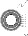
- Fig. 1 schematically depicts an example of the combined gradient coil and shim coil assembly 10 for use in MR-devices.
- the assembly 10 comprises a cylindric carrier tube 11 usually made of glass fiber material, a gradient coil system 12 arranged concentrically onto the carrier tube 11, a cooling tube assembly 13 positioned around the gradient coils 12, and an active shim coil system 14.
- PCB flexible printed circuit board 22
- the flexible printed circuit board 22 on which the active shim coil system 14 is constructed has the shape of a foil or a film, which is wound around the cooling tube assembly 13.
- the shim coil system 14 can be manufactured using a micromechanical process or a photolithographic process.
- electronic components can be integrated on the PCB 22, in particular discrete components such as resistors or semiconductors for switching or measuring tasks.
- the cooling tube assembly 13 can be made of a plurality of copper tubes assembled in a cage-like manner or using a single meander structure made from either welded or soldered tubes or a single 3D print structure.
- Another embodiment of the invention comprising screening coils 18 around the shim coil system 14 is shown in the schematic sectional drawing of Fig. 4 .
- the shim coil system 14 comprises a plurality of layers of flexible PCB 22 which are wound concentrically around the axis of the cylindric carrier tube 11.
- the sealing compound 15 is shown in Fig. 2a , whereas other parts such as gradient and screen coils or cooling system are omitted.
- the embodiment shown in Fig. 2a has just two flexible PCB layers, each of which having a shim coil layer on either side of the PCB, i.e. a first shim coil layer 14' and a second shim coil layer 14".
- the adjacent layers 14'; 14" are separated by a spacer element 17, in particular a flexible filament or flexible profile of a desired thickness, preferably an electrically non-conducting thread.
- Fig. 2b shows in a schematic spatial side view a cylindrically wound shim coil assembly 14 according to the invention on which a spacer element 17 in form of a separating thread or filament is wound around the cylinder in a helical manner.
- FIG. 3 depicts an embodiment of the combined coil assembly 10 according to the present invention before being introduced into an MR magnet 20 and an MR probe 21 to be inserted afterwards into the inner cavity of the combined coil assembly 10 for performing MR measurements.
- Figures 5a and 5b show two typical coil types which are conveniently used for coil patterns in gradients and shims, namely solenoid coils and saddle coil pairs, first contributing predominantly to the axial field and second contributing predominantly to the transverse field where axial refers to the cylinder axis, usually the z-axis of the coordinate system.
- FIG. 5a shows a solenoid coil used in embodiments of the active shim coil system according to the invention.
- Fig. 5b a 3D-view of a pair of saddle coils with a coil interconnection 19' is shown. This may be used in other embodiments of the invention.
- Fig. 6 shows a 3D-view of another pair of meandering saddle coils with a coil interconnection 19 used in further embodiments of the invention.
- This exemplary coil pattern comprises two side by side coils which are connected in series.
- a connecting trace 19 usually interferes with the coil turns if located on the same layer.
- the coil interconnection 19; 19' can be realized by selecting a two-sided layout on a carrier.
- Fig. 7 in a schematic partial sectional drawing of a shim coil illustrates the shim coil radius R coil in relation to the radius R connect of a coil interconnection. It shows the solution to avoid interference by putting the interconnections on a different radius i.e. on a different layer to avoid short circuits.
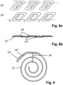
- connections from top layer to bottom layer allow routing these traces in the unused areas between the coils located on the opposite layer of the PCB, as shown in Figures 8a and 8b .
- vias connection layers
- the single working step of applying this foil replaces about four work steps of conventional assembling technique, where the coil layers are attached to the cylindrical support structure followed by manually soldering and routing the interconnect wires.
- Fig. 8a shows in a schematic spatial view of an embodiment of the active shim coil system according to the invention comprising two shim coil layers 14'; 14" arranged in parallel on either side of a flexible printed circuit board (the latter not been shown in this figure).
- Each shim coil layer 14'; 14" has three pairs of meandering saddle coils with coil interconnections between neighboring coils.
- FIG. 8b This situation is depicted in Fig. 8b in a schematic sectional drawing of the two shim coil layers 14'; 14" of Fig. 8a on either side of the flexible PCB 22, with neighboring shim coil layers 14'; 14" each having coil interconnections.
- Fig. 9 shows a schematic sectional drawing of a two-layered embodiment of the active shim coil system 14 according to the invention having a first shim coil layer 14' and a second shim coil layer 14" wound in helical shape and comprising an positioning/alignment pin 16.
- This is a possible realization of a flexible shim coil that comprises multiple layers, but is fabricated as a single piece, again combining multiple work steps.
- One or more locator pins may serve to align the layers and eliminate relative positioning errors.
- the lower components can be hooked into a first winding with a second set of holes.
Landscapes
- Physics & Mathematics (AREA)
- Engineering & Computer Science (AREA)
- Power Engineering (AREA)
- Condensed Matter Physics & Semiconductors (AREA)
- General Physics & Mathematics (AREA)
- Manufacturing & Machinery (AREA)
- Health & Medical Sciences (AREA)
- Environmental & Geological Engineering (AREA)
- Toxicology (AREA)
- Magnetic Resonance Imaging Apparatus (AREA)
Claims (12)
- Kombinierte Gradientenspulen- und Shimspulen-Anordnung (10) zur Verwendung in MR-Geräten, umfassend:- ein zylindrisches Trägerrohr (11),- ein Gradientenspulen-System (12), das konzentrisch auf dem Trägerrohr (11) angeordnet ist,- eine Kühlrohr-Anordnung (13), die um die Gradientenspulen (12) herum positioniert ist, und- ein aktives Shimspulen-System (14),wobei das aktive Shimspulen-System (14) auf einer flexiblen Leiterplatte (22) aufgebaut ist unddie Anordnung ferner umfasst:ein Dichtungsverbund (15) mit einem flüssigen Reaktionsharz, das die Komponenten der Anordnung (10) umschließt, um ein zylindrisches Rohr zu bilden und die Hohlräume des Gradienten- (12) und des Shimspulen-Systems (14) und zwischen den Spulen (12; 14) und dem Trägerrohr (11) zu füllen, wobei das Shimspulen-System (14) eine Vielzahl von Schichten (14'; 14") einer flexiblen Leiterplatte (22) umfasst, wobei die Schichten (14'; 14") konzentrisch um die Achse des zylindrischen Trägerrohrs (11) gewickelt sind, wobei die Schichten (14'; 14") der flexiblen Leiterplatte (22) durch ein Distanzelement (17) getrennt sind,dadurch gekennzeichnet,dass das flüssige Reaktionsharz mit einem wärmeleitenden Füllstoff angereichert ist, unddass das Distanzelement (17) spiralförmig um jede Schicht (14'; 14") der flexiblen Leiterplatte (22) gewickelt ist, um die Vielzahl von Shimspulen (14) voneinander zu trennen und einen spiralförmigen Spalt zwischen den Schichten (14'; 14") zu erzeugen, der es dem Dichtungsverbund (15) ermöglicht, sich auszubreiten und den Spalt zu füllen.
- Anordnung nach Anspruch 1, dadurch gekennzeichnet, dass die flexible Leiterplatte (22), auf der das aktive Shimspulen-System (14) aufgebaut ist, die Form einer Folie oder eines Films hat, die/der um die Kühlrohr-Anordnung (13) gewickelt ist.
- Anordnung nach Anspruch 1 oder 2, dadurch gekennzeichnet, dass die flexible Leiterplatte (22) Positionierstifte (16) und/oder Referenzlöcher umfasst, die zur präzisen Montage in einem der konzentrisch unteren Bauteile der Gruppe verwendet werden, so dass die Shimspulen des aktiven Shimspulen-Systems (14) korrekt positioniert sind.
- Anordnung nach einem der vorhergehenden Ansprüche, dadurch gekennzeichnet, dass die flexible Leiterplatte (22) unter Verwendung eines mikromechanischen Verfahrens oder eines photolithographischen Verfahrens hergestellt wird.
- Anordnung nach einem der vorhergehenden Ansprüche, dadurch gekennzeichnet, dass das Distanzelement (17) ein flexibles Filament oder ein flexibles Profil mit einer gewünschten Dicke, vorzugsweise ein elektrisch nichtleitender Faden, ist.
- Anordnung nach einem der vorhergehenden Ansprüche, dadurch gekennzeichnet, dass das Distanzelement (17), insbesondere der elektrisch nichtleitende Faden, aus einem Polyimid, vorzugsweise Kapton, besteht.
- Anordnung nach einem der vorhergehenden Ansprüche, dadurch gekennzeichnet, dass elektronische Bauelemente auf der flexiblen Leiterplatte (22) integriert sind, insbesondere einzelne Bauteile wie Widerstände oder Halbleiter für Schalt- oder Messaufgaben.
- Anordnung nach einem der vorhergehenden Ansprüche, dadurch gekennzeichnet, dass eine Spulen-Verbindung (19; 19') durch Auswahl eines zweiseitigen Aufbaus auf einem Träger realisiert wird.
- Anordnung nach einem der vorhergehenden Ansprüche, dadurch gekennzeichnet, dass die Kühlrohr-Anordnung (13) aus einer Mehrzahl von Kupferrohren besteht, die in käfigartiger Weise oder unter Verwendung einer einzelnen Mäanderstruktur aus entweder geschweißten oder gelöteten Rohren oder einer einzelnen 3D-Druckstruktur aufgebaut ist.
- Verfahren zur Herstellung einer Anordnung (10) nach einem der vorhergehenden Ansprüche, umfassend die folgenden Verfahrensschritte:- Bereitstellen eines zylindrischen Trägerrohrs (11), das z. B. aus Glasfaser hergestellt ist;- konzentrisches Anbringen des Gradientenspulen-Systems (12) auf das zylindrische Trägerrohr (11);- Anbringen der Kühlrohr-Anordnung (13) um die Gradientenspulen (12) herum;- Wickeln und Positionieren des aktiven Shimspulen-Systems (14), das auf einer flexiblen Leiterplatte (22) als fertiges Bauteil aufgebaut ist, auf der Außenfläche der Kühlrohr-Anordnung (13);- Vergießen oder Vakuumgießen der resultierenden konzentrischen Anordnung als Ganze mit einem Dichtungsverbund (15) mit einem flüssigen Reaktionsharz, das mit einem wärmeleitenden Füllstoff angereichert ist, der sowohl elektrisch isolierend als auch gleichzeitig gut wärmeleitend ist, wodurch die Hohlräume der Gradientenspulen- (12) und Shimspulen-Systeme (14) sowie zwischen den Spulen (12; 14) und dem Trägerrohr (11) gefüllt werden, wobei das aktive Shimspulen-System (14) mindestens zwei Schichten (14'; 14") von Shimspulen auf der flexiblen Leiterplatte (22) umfasst, die konzentrisch um die Kühlrohr-Anordnung (13) gewickelt sind, und dass ein Trennfaden (17) spiralförmig zwischen den mindestens zwei Schichten (14'; 14") von Shimspulen gewickelt ist.
- Verfahren nach Anspruch 10, dadurch gekennzeichnet, dass Positionierstifte (16) und/oder Referenzlöcher auf der flexiblen Leiterplatte (22) für die präzise Montage in einem der konzentrisch unteren Bauteile der Anordnung verwendet werden, so dass die Shimspulen des aktiven Shimspulen-Systems (14) korrekt positioniert sind, insbesondere die unteren Komponenten in eine erste Wicklung mit einem zweiten Satz von Löchern eingehakt sind.
- Verfahren nach einem der Ansprüche 10 oder 11, dadurch gekennzeichnet, dass Abschirm- oder Rasterspulen (18), die vorzugsweise auf ähnliche Weise hergestellt werden wie das Gradientenspulen-System (12), vor dem Schritt des Vakuumgießens auf den äußeren Umfang des aktiven Shimspulen-Systems (14) aufgebracht werden.
Priority Applications (4)
| Application Number | Priority Date | Filing Date | Title |
|---|---|---|---|
| HUE23315058A HUE071402T2 (hu) | 2023-03-21 | 2023-03-21 | Alátéttekercsek kompakt MRI gradiens rendszerhez többrétegû flexibilis nyomtatott áramköri lapok alapján, valamint vezetõrétegek elrendezési sémája |
| EP23315058.0A EP4435459B1 (de) | 2023-03-21 | 2023-03-21 | Shimspulen für ein kompaktes mrt-gradientensystem auf basis von mehrschichtigen flexiblen leiterplatten und anordnungsschema für leiterschichten |
| US18/605,413 US12566227B2 (en) | 2023-03-21 | 2024-03-14 | Shim coils for a compact MRI gradient system based on multilayer flexible printed circuit boards and arrangement scheme of conductor layers |
| CN202410309434.3A CN118688694A (zh) | 2023-03-21 | 2024-03-19 | 用于基于多层柔性印刷电路板的紧凑型mri梯度系统的匀场线圈以及导体层的布置方案 |
Applications Claiming Priority (1)
| Application Number | Priority Date | Filing Date | Title |
|---|---|---|---|
| EP23315058.0A EP4435459B1 (de) | 2023-03-21 | 2023-03-21 | Shimspulen für ein kompaktes mrt-gradientensystem auf basis von mehrschichtigen flexiblen leiterplatten und anordnungsschema für leiterschichten |
Publications (2)
| Publication Number | Publication Date |
|---|---|
| EP4435459A1 EP4435459A1 (de) | 2024-09-25 |
| EP4435459B1 true EP4435459B1 (de) | 2025-05-07 |
Family
ID=86226584
Family Applications (1)
| Application Number | Title | Priority Date | Filing Date |
|---|---|---|---|
| EP23315058.0A Active EP4435459B1 (de) | 2023-03-21 | 2023-03-21 | Shimspulen für ein kompaktes mrt-gradientensystem auf basis von mehrschichtigen flexiblen leiterplatten und anordnungsschema für leiterschichten |
Country Status (4)
| Country | Link |
|---|---|
| US (1) | US12566227B2 (de) |
| EP (1) | EP4435459B1 (de) |
| CN (1) | CN118688694A (de) |
| HU (1) | HUE071402T2 (de) |
Family Cites Families (19)
| Publication number | Priority date | Publication date | Assignee | Title |
|---|---|---|---|---|
| JPH08196518A (ja) | 1995-01-20 | 1996-08-06 | Toshiba Corp | Mri装置 |
| JPH11133129A (ja) * | 1997-10-31 | 1999-05-21 | Jeol Ltd | Nmr用磁石装置 |
| DE10032836C1 (de) * | 2000-07-06 | 2002-01-17 | Siemens Ag | Magnetresonanzgerät mit einem Gradientenspulensystem |
| DE20203908U1 (de) * | 2002-03-11 | 2002-06-06 | Siemens AG, 80333 München | Schichtstruktur |
| JP4335799B2 (ja) * | 2002-05-02 | 2009-09-30 | シーメンス アクチエンゲゼルシヤフト | 磁気共鳴断層撮影装置のための傾斜コイルシステム |
| DE10315539A1 (de) * | 2003-04-04 | 2004-10-28 | Siemens Ag | Gradientenspule |
| WO2005029111A1 (en) * | 2003-09-19 | 2005-03-31 | Multi-Dimension Technology, Llc | Cylindrical bi-planar gradient coil for mri |
| JP4653439B2 (ja) * | 2004-08-10 | 2011-03-16 | ジーイー・メディカル・システムズ・グローバル・テクノロジー・カンパニー・エルエルシー | 勾配コイルおよびmri装置 |
| JP2010088618A (ja) * | 2008-10-07 | 2010-04-22 | Toshiba Corp | 磁場発生コイル装置 |
| DE102010004302A1 (de) * | 2010-01-11 | 2011-07-14 | Siemens Aktiengesellschaft, 80333 | Medizinische Bildaufnahmeeinrichtung zur Magnetresonanz- und PET-Bildgebung |
| DE102010015631B4 (de) * | 2010-04-20 | 2012-09-27 | Siemens Aktiengesellschaft | Gradientenspulenanordnung und Herstellungsverfahren |
| EP2588877A1 (de) * | 2010-06-30 | 2013-05-08 | Koninklijke Philips Electronics N.V. | Gekühlte mr-spulenanordnung |
| JP2012170719A (ja) * | 2011-02-23 | 2012-09-10 | Hitachi Medical Corp | 磁気共鳴イメージング装置及び磁場補正用コイルの製造方法 |
| DE102011077743B3 (de) * | 2011-06-17 | 2012-11-22 | Siemens Ag | Verfahren zur Herstellung einer Gradientenspulen-Baugruppe sowie Wickeldorn |
| US20140184226A1 (en) * | 2012-12-27 | 2014-07-03 | General Electric Company | System and apparatus for active high order shimming |
| DE102013204952B3 (de) | 2013-03-20 | 2014-05-15 | Bruker Biospin Ag | Aktiv abgeschirmtes zylinderförmiges Gradientenspulensystem mit passiver HF-Abschirmung für NMR-Apparate |
| US9638776B2 (en) | 2014-08-22 | 2017-05-02 | General Electric Company | Nested coil configuration of active shims in MRI systems |
| DE102018221322A1 (de) | 2018-12-10 | 2020-06-10 | Bruker Switzerland Ag | Verfahren zum Laden einer HTS-Shim-Vorrichtung und Magnetanordnung |
| DE102022207489A1 (de) | 2022-07-21 | 2024-02-01 | Bruker Switzerland Ag | Aktive Reduzierung der temperaturinduzierten Shimdrift bei NMR-Magnetsystemen |
-
2023
- 2023-03-21 HU HUE23315058A patent/HUE071402T2/hu unknown
- 2023-03-21 EP EP23315058.0A patent/EP4435459B1/de active Active
-
2024
- 2024-03-14 US US18/605,413 patent/US12566227B2/en active Active
- 2024-03-19 CN CN202410309434.3A patent/CN118688694A/zh active Pending
Also Published As
| Publication number | Publication date |
|---|---|
| EP4435459A1 (de) | 2024-09-25 |
| US20240319303A1 (en) | 2024-09-26 |
| CN118688694A (zh) | 2024-09-24 |
| HUE071402T2 (hu) | 2025-08-28 |
| US12566227B2 (en) | 2026-03-03 |
Similar Documents
| Publication | Publication Date | Title |
|---|---|---|
| JP5364288B2 (ja) | 傾斜コイルアセンブリ、傾斜コイルアセンブリを含むマグネットアセンブリ及び、傾斜コイルアセンブリを製造する方法 | |
| US5773976A (en) | Shimming in magnetic resonance imaging | |
| JP5894601B2 (ja) | 傾斜磁場コイル装置及び磁気共鳴イメージング装置 | |
| US7777489B2 (en) | Magnetic resonance imaging apparatus, shield coil, manufacturing method of shield coil, and driving method of magnetic resonance imaging apparatus | |
| EP0629875B1 (de) | Gradientenspule für magnetische Resonanz und Hochfrequenz-Abschirmung | |
| US6930482B2 (en) | Time-variable magnetic fields generator for a magnetic resonance apparatus | |
| US7501826B2 (en) | Dividing wall separating the RF antenna from the patient chamber in an MR scanner | |
| JP5837954B2 (ja) | Nmr装置のためのパッシブrfシールドを有するアクティブシールドされた円筒状傾斜磁場コイル装置 | |
| JPH06277193A (ja) | 磁気共鳴撮像システム | |
| JP6697187B2 (ja) | 固体nmr装置及びマジック角調整方法 | |
| US8766636B2 (en) | MRI short coils | |
| JP2008527376A (ja) | 分割可動キャパシタンスバンドを有するnmrrfコイル | |
| JP2011510261A (ja) | アーチ状鞍形核磁気共鳴用無線周波数コイル | |
| WO2010018479A1 (en) | Magnetic resonance rf coil | |
| US12566227B2 (en) | Shim coils for a compact MRI gradient system based on multilayer flexible printed circuit boards and arrangement scheme of conductor layers | |
| CN109804260B (zh) | 共面的射频线圈馈电 | |
| US5804968A (en) | Gradient coils with reduced eddy currents | |
| WO2010004491A1 (en) | Toroidal coil arrangement | |
| US10809328B2 (en) | High density magnetic resonant imaging gradient driver with integrated cooling | |
| US12504490B2 (en) | Detector unit for a magnetic resonance device with gradient coil unit, shim unit, and radio-frequency antenna unit | |
| US7368915B2 (en) | Shim board system | |
| JP3524607B2 (ja) | 磁気共鳴イメージング装置用磁場発生コイル及びこれを用いた磁気共鳴イメージング装置 | |
| JPH10155760A (ja) | 磁場発生用コイルユニット | |
| JP7675871B2 (ja) | 均一磁場発生のための超伝導磁石システム | |
| JP2008000324A (ja) | 核磁気共鳴イメージング装置の傾斜磁場コイル装置 |
Legal Events
| Date | Code | Title | Description |
|---|---|---|---|
| PUAI | Public reference made under article 153(3) epc to a published international application that has entered the european phase |
Free format text: ORIGINAL CODE: 0009012 |
|
| STAA | Information on the status of an ep patent application or granted ep patent |
Free format text: STATUS: REQUEST FOR EXAMINATION WAS MADE |
|
| 17P | Request for examination filed |
Effective date: 20231117 |
|
| AK | Designated contracting states |
Kind code of ref document: A1 Designated state(s): AL AT BE BG CH CY CZ DE DK EE ES FI FR GB GR HR HU IE IS IT LI LT LU LV MC ME MK MT NL NO PL PT RO RS SE SI SK SM TR |
|
| GRAP | Despatch of communication of intention to grant a patent |
Free format text: ORIGINAL CODE: EPIDOSNIGR1 |
|
| STAA | Information on the status of an ep patent application or granted ep patent |
Free format text: STATUS: GRANT OF PATENT IS INTENDED |
|
| INTG | Intention to grant announced |
Effective date: 20241218 |
|
| P01 | Opt-out of the competence of the unified patent court (upc) registered |
Free format text: CASE NUMBER: APP_109/2025 Effective date: 20250102 |
|
| GRAS | Grant fee paid |
Free format text: ORIGINAL CODE: EPIDOSNIGR3 |
|
| GRAA | (expected) grant |
Free format text: ORIGINAL CODE: 0009210 |
|
| STAA | Information on the status of an ep patent application or granted ep patent |
Free format text: STATUS: THE PATENT HAS BEEN GRANTED |
|
| AK | Designated contracting states |
Kind code of ref document: B1 Designated state(s): AL AT BE BG CH CY CZ DE DK EE ES FI FR GB GR HR HU IE IS IT LI LT LU LV MC ME MK MT NL NO PL PT RO RS SE SI SK SM TR |
|
| REG | Reference to a national code |
Ref country code: GB Ref legal event code: FG4D |
|
| REG | Reference to a national code |
Ref country code: CH Ref legal event code: EP |
|
| REG | Reference to a national code |
Ref country code: DE Ref legal event code: R096 Ref document number: 602023003371 Country of ref document: DE |
|
| REG | Reference to a national code |
Ref country code: IE Ref legal event code: FG4D |
|
| REG | Reference to a national code |
Ref country code: HU Ref legal event code: AG4A Ref document number: E071402 Country of ref document: HU |
|
| REG | Reference to a national code |
Ref country code: NL Ref legal event code: MP Effective date: 20250507 |
|
| PG25 | Lapsed in a contracting state [announced via postgrant information from national office to epo] |
Ref country code: PT Free format text: LAPSE BECAUSE OF FAILURE TO SUBMIT A TRANSLATION OF THE DESCRIPTION OR TO PAY THE FEE WITHIN THE PRESCRIBED TIME-LIMIT Effective date: 20250908 Ref country code: ES Free format text: LAPSE BECAUSE OF FAILURE TO SUBMIT A TRANSLATION OF THE DESCRIPTION OR TO PAY THE FEE WITHIN THE PRESCRIBED TIME-LIMIT Effective date: 20250507 Ref country code: FI Free format text: LAPSE BECAUSE OF FAILURE TO SUBMIT A TRANSLATION OF THE DESCRIPTION OR TO PAY THE FEE WITHIN THE PRESCRIBED TIME-LIMIT Effective date: 20250507 |
|
| REG | Reference to a national code |
Ref country code: LT Ref legal event code: MG9D |
|
| PG25 | Lapsed in a contracting state [announced via postgrant information from national office to epo] |
Ref country code: NO Free format text: LAPSE BECAUSE OF FAILURE TO SUBMIT A TRANSLATION OF THE DESCRIPTION OR TO PAY THE FEE WITHIN THE PRESCRIBED TIME-LIMIT Effective date: 20250807 Ref country code: GR Free format text: LAPSE BECAUSE OF FAILURE TO SUBMIT A TRANSLATION OF THE DESCRIPTION OR TO PAY THE FEE WITHIN THE PRESCRIBED TIME-LIMIT Effective date: 20250808 |
|
| PG25 | Lapsed in a contracting state [announced via postgrant information from national office to epo] |
Ref country code: PL Free format text: LAPSE BECAUSE OF FAILURE TO SUBMIT A TRANSLATION OF THE DESCRIPTION OR TO PAY THE FEE WITHIN THE PRESCRIBED TIME-LIMIT Effective date: 20250507 Ref country code: NL Free format text: LAPSE BECAUSE OF FAILURE TO SUBMIT A TRANSLATION OF THE DESCRIPTION OR TO PAY THE FEE WITHIN THE PRESCRIBED TIME-LIMIT Effective date: 20250507 |
|
| REG | Reference to a national code |
Ref country code: AT Ref legal event code: MK05 Ref document number: 1793025 Country of ref document: AT Kind code of ref document: T Effective date: 20250507 |
|
| PG25 | Lapsed in a contracting state [announced via postgrant information from national office to epo] |
Ref country code: BG Free format text: LAPSE BECAUSE OF FAILURE TO SUBMIT A TRANSLATION OF THE DESCRIPTION OR TO PAY THE FEE WITHIN THE PRESCRIBED TIME-LIMIT Effective date: 20250507 |
|
| PG25 | Lapsed in a contracting state [announced via postgrant information from national office to epo] |
Ref country code: HR Free format text: LAPSE BECAUSE OF FAILURE TO SUBMIT A TRANSLATION OF THE DESCRIPTION OR TO PAY THE FEE WITHIN THE PRESCRIBED TIME-LIMIT Effective date: 20250507 |
|
| PG25 | Lapsed in a contracting state [announced via postgrant information from national office to epo] |
Ref country code: AT Free format text: LAPSE BECAUSE OF FAILURE TO SUBMIT A TRANSLATION OF THE DESCRIPTION OR TO PAY THE FEE WITHIN THE PRESCRIBED TIME-LIMIT Effective date: 20250507 |
|
| PG25 | Lapsed in a contracting state [announced via postgrant information from national office to epo] |
Ref country code: RS Free format text: LAPSE BECAUSE OF FAILURE TO SUBMIT A TRANSLATION OF THE DESCRIPTION OR TO PAY THE FEE WITHIN THE PRESCRIBED TIME-LIMIT Effective date: 20250807 |
|
| PG25 | Lapsed in a contracting state [announced via postgrant information from national office to epo] |
Ref country code: IS Free format text: LAPSE BECAUSE OF FAILURE TO SUBMIT A TRANSLATION OF THE DESCRIPTION OR TO PAY THE FEE WITHIN THE PRESCRIBED TIME-LIMIT Effective date: 20250907 |
|
| PG25 | Lapsed in a contracting state [announced via postgrant information from national office to epo] |
Ref country code: LV Free format text: LAPSE BECAUSE OF FAILURE TO SUBMIT A TRANSLATION OF THE DESCRIPTION OR TO PAY THE FEE WITHIN THE PRESCRIBED TIME-LIMIT Effective date: 20250507 |
|
| PG25 | Lapsed in a contracting state [announced via postgrant information from national office to epo] |
Ref country code: SM Free format text: LAPSE BECAUSE OF FAILURE TO SUBMIT A TRANSLATION OF THE DESCRIPTION OR TO PAY THE FEE WITHIN THE PRESCRIBED TIME-LIMIT Effective date: 20250507 Ref country code: DK Free format text: LAPSE BECAUSE OF FAILURE TO SUBMIT A TRANSLATION OF THE DESCRIPTION OR TO PAY THE FEE WITHIN THE PRESCRIBED TIME-LIMIT Effective date: 20250507 |
|
| PG25 | Lapsed in a contracting state [announced via postgrant information from national office to epo] |
Ref country code: CZ Free format text: LAPSE BECAUSE OF FAILURE TO SUBMIT A TRANSLATION OF THE DESCRIPTION OR TO PAY THE FEE WITHIN THE PRESCRIBED TIME-LIMIT Effective date: 20250507 |
|
| PG25 | Lapsed in a contracting state [announced via postgrant information from national office to epo] |
Ref country code: EE Free format text: LAPSE BECAUSE OF FAILURE TO SUBMIT A TRANSLATION OF THE DESCRIPTION OR TO PAY THE FEE WITHIN THE PRESCRIBED TIME-LIMIT Effective date: 20250507 |
|
| PG25 | Lapsed in a contracting state [announced via postgrant information from national office to epo] |
Ref country code: SK Free format text: LAPSE BECAUSE OF FAILURE TO SUBMIT A TRANSLATION OF THE DESCRIPTION OR TO PAY THE FEE WITHIN THE PRESCRIBED TIME-LIMIT Effective date: 20250507 |
|
| PG25 | Lapsed in a contracting state [announced via postgrant information from national office to epo] |
Ref country code: IT Free format text: LAPSE BECAUSE OF FAILURE TO SUBMIT A TRANSLATION OF THE DESCRIPTION OR TO PAY THE FEE WITHIN THE PRESCRIBED TIME-LIMIT Effective date: 20250507 |
|
| REG | Reference to a national code |
Ref country code: DE Ref legal event code: R097 Ref document number: 602023003371 Country of ref document: DE |
|
| PLBE | No opposition filed within time limit |
Free format text: ORIGINAL CODE: 0009261 |
|
| STAA | Information on the status of an ep patent application or granted ep patent |
Free format text: STATUS: NO OPPOSITION FILED WITHIN TIME LIMIT |
|
| REG | Reference to a national code |
Ref country code: CH Ref legal event code: L10 Free format text: ST27 STATUS EVENT CODE: U-0-0-L10-L00 (AS PROVIDED BY THE NATIONAL OFFICE) Effective date: 20260318 |
|
| PGFP | Annual fee paid to national office [announced via postgrant information from national office to epo] |
Ref country code: DE Payment date: 20260320 Year of fee payment: 4 |
|
| 26N | No opposition filed |
Effective date: 20260210 |
|
| PGFP | Annual fee paid to national office [announced via postgrant information from national office to epo] |
Ref country code: HU Payment date: 20260313 Year of fee payment: 4 |
|
| PGFP | Annual fee paid to national office [announced via postgrant information from national office to epo] |
Ref country code: FR Payment date: 20260324 Year of fee payment: 4 |