EP4435338A1 - Klimaanlage - Google Patents
Klimaanlage Download PDFInfo
- Publication number
- EP4435338A1 EP4435338A1 EP21964132.1A EP21964132A EP4435338A1 EP 4435338 A1 EP4435338 A1 EP 4435338A1 EP 21964132 A EP21964132 A EP 21964132A EP 4435338 A1 EP4435338 A1 EP 4435338A1
- Authority
- EP
- European Patent Office
- Prior art keywords
- refrigerant
- heat exchanger
- valve
- controller
- temperature
- Prior art date
- Legal status (The legal status is an assumption and is not a legal conclusion. Google has not performed a legal analysis and makes no representation as to the accuracy of the status listed.)
- Withdrawn
Links
Images


Classifications
-
- F—MECHANICAL ENGINEERING; LIGHTING; HEATING; WEAPONS; BLASTING
- F24—HEATING; RANGES; VENTILATING
- F24F—AIR-CONDITIONING; AIR-HUMIDIFICATION; VENTILATION; USE OF AIR CURRENTS FOR SCREENING
- F24F11/00—Control or safety arrangements
- F24F11/30—Control or safety arrangements for purposes related to the operation of the system, e.g. for safety or monitoring
- F24F11/32—Responding to malfunctions or emergencies
- F24F11/36—Responding to malfunctions or emergencies to leakage of heat-exchange fluid
-
- F—MECHANICAL ENGINEERING; LIGHTING; HEATING; WEAPONS; BLASTING
- F25—REFRIGERATION OR COOLING; COMBINED HEATING AND REFRIGERATION SYSTEMS; HEAT PUMP SYSTEMS; MANUFACTURE OR STORAGE OF ICE; LIQUEFACTION SOLIDIFICATION OF GASES
- F25B—REFRIGERATION MACHINES, PLANTS OR SYSTEMS; COMBINED HEATING AND REFRIGERATION SYSTEMS; HEAT PUMP SYSTEMS
- F25B41/00—Fluid-circulation arrangements
- F25B41/20—Disposition of valves, e.g. of on-off valves or flow control valves
-
- F—MECHANICAL ENGINEERING; LIGHTING; HEATING; WEAPONS; BLASTING
- F24—HEATING; RANGES; VENTILATING
- F24F—AIR-CONDITIONING; AIR-HUMIDIFICATION; VENTILATION; USE OF AIR CURRENTS FOR SCREENING
- F24F2140/00—Control inputs relating to system states
- F24F2140/10—Pressure
- F24F2140/12—Heat-exchange fluid pressure
-
- F—MECHANICAL ENGINEERING; LIGHTING; HEATING; WEAPONS; BLASTING
- F24—HEATING; RANGES; VENTILATING
- F24F—AIR-CONDITIONING; AIR-HUMIDIFICATION; VENTILATION; USE OF AIR CURRENTS FOR SCREENING
- F24F2140/00—Control inputs relating to system states
- F24F2140/20—Heat-exchange fluid temperature
-
- F—MECHANICAL ENGINEERING; LIGHTING; HEATING; WEAPONS; BLASTING
- F25—REFRIGERATION OR COOLING; COMBINED HEATING AND REFRIGERATION SYSTEMS; HEAT PUMP SYSTEMS; MANUFACTURE OR STORAGE OF ICE; LIQUEFACTION SOLIDIFICATION OF GASES
- F25B—REFRIGERATION MACHINES, PLANTS OR SYSTEMS; COMBINED HEATING AND REFRIGERATION SYSTEMS; HEAT PUMP SYSTEMS
- F25B2313/00—Compression machines, plants or systems with reversible cycle not otherwise provided for
- F25B2313/027—Compression machines, plants or systems with reversible cycle not otherwise provided for characterised by the reversing means
- F25B2313/02741—Compression machines, plants or systems with reversible cycle not otherwise provided for characterised by the reversing means using one four-way valve
Definitions
- the present disclosure relates to an air conditioner.
- An air conditioner includes a compressor that discharges high-temperature, high-pressure refrigerant to a refrigerant circuit, and a heat exchanger.
- PTL 1 describes determining a refrigerant leakage by detecting a decrease in pressure in a heat exchanger while refrigerant is trapped in the heat exchanger by closing a refrigerant inlet and a refrigerant outlet of the heat exchanger.
- the refrigerant When a large amount of refrigerant is trapped in a heat exchanger, the refrigerant may be present in the heat exchanger in a liquid state or a two-phase state. In such a case, even if a refrigerant leakage has occurred in the heat exchanger, a decrease in pressure of the refrigerant in the heat exchanger cannot be detected with high accuracy until the refrigerant in the heat exchanger is gasified and a pressure thereof is made equal to a saturation pressure. As a result, it may take time to determine the refrigerant leakage.
- An object of the present disclosure is to provide an air conditioner that can determine a refrigerant leakage while causing refrigerant in a refrigerant circuit to be suitable for determination of a refrigerant leakage.
- the present disclosure relates to an air conditioner.
- the air conditioner includes: a compressor; a first heat exchanger; a second heat exchanger; a first valve; a second valve; a refrigerant circuit in which refrigerant circulates in order of the compressor, the first heat exchanger, the first valve, the second heat exchanger, the second valve, and the compressor; a first temperature sensor configured to detect a first temperature of a heat medium that exchanges heat with the refrigerant flowing through the first heat exchanger; a second temperature sensor configured to detect a second temperature of a heat medium that exchanges heat with the refrigerant flowing through the second heat exchanger; a first pressure sensor configured to detect a first pressure of the refrigerant of the first heat exchanger; a second pressure sensor configured to detect a second pressure of the refrigerant of the second heat exchanger; and a controller.
- the controller is configured to determine a refrigerant leakage based on the first pressure while closing the first valve and the second valve when the first temperature is higher than the second temperature and determine a refrigerant leakage based on the second pressure while closing the first valve and the second valve when the second temperature is higher than the first temperature.
- an air conditioner can be provided that can determine a refrigerant leakage while causing refrigerant in a refrigerant circuit to be suitable for determination of a refrigerant leakage.
- Fig. 1 is a refrigerant circuit diagram showing a configuration of an air conditioner 100 (Embodiment 1).
- air conditioner 100 includes a compressor 1, a first heat exchanger 2, an electronic expansion valve 3, a second heat exchanger 4, a first valve 11, a second valve 12, and a controller 50. These devices are coupled by a refrigerant pipe 10.
- First valve 11 that closes refrigerant pipe 10 is provided between electronic expansion valve 3 and second heat exchanger 4.
- Second valve 12 that closes refrigerant pipe 10 is provided between the second heat exchanger and compressor 1.
- Each of first valve 11 and second valve 12 is configured of, for example, an electromagnetic valve.
- Each of first valve 11 and second valve 12 may be configured of an electronic expansion valve.
- First valve 11 and second valve 12 constitute a closing mechanism that closes the refrigerant circuit (refrigerant pipe 10).
- First heat exchanger 2 is located on the high pressure side of the refrigerant circuit in driving of compressor 1.
- First heat exchanger 2 thus functions as a condenser.
- Second heat exchanger 4 is located on the low pressure side of the refrigerant circuit in driving of compressor 1.
- Second heat exchanger 4 thus functions as an evaporator.
- air conditioner 100 functions as a heater that heats the indoor space.
- air conditioner 100 functions as a cooling apparatus or a freezing apparatus that cools the indoor space.
- Controller 50 includes a processor 51 and a memory 52.
- Memory 52 includes a read only memory (ROM), a random access memory (RAM), and a flash memory.
- An operating system, an application program, and various types of data are stored in the flash memory.
- Processor 51 executes the operating system and the application program stored in memory 52.
- Controller 50 refers to the various types of data stored in memory 52 in execution of the application program.
- controller 50 is disposed in the indoor unit.
- Controller 50 may be disposed in the outdoor unit.
- Compressor 1 increases the pressure of sucked refrigerant and then discharges the refrigerant, thereby circulating the refrigerant in the refrigerant circuit.
- First heat exchanger 2 performs heat exchange between the refrigerant flowing in first heat exchanger 2 and the outdoor air.
- High-temperature, high-pressure gas refrigerant flows from compressor 1 into first heat exchanger 2.
- a first temperature sensor 21 is provided at a refrigerant inlet of first heat exchanger 2.
- First temperature sensor 21 detects a temperature of a heat medium that exchanges heat with the refrigerant flowing through first heat exchanger 2.
- the heat medium is the air present in the space in which first heat exchanger 2 is installed. In other words, first temperature sensor 21 detects an ambient temperature of first heat exchanger 2.
- a first pressure sensor 31 is provided at a refrigerant outlet of first heat exchanger 2.
- First pressure sensor 31 detects a pressure of the refrigerant of first heat exchanger 2. The positions where first temperature sensor 21 and first pressure sensor 31 are disposed may be reversed.
- Electronic expansion valve 3 adjusts a degree of opening to adjust a flow rate and a pressure of the refrigerant.
- Electronic expansion valve 3 expands the refrigerant condensed by first heat exchanger 2 to reduce the pressure of the refrigerant.
- Electronic expansion valve 3 is configured of a decompressor.
- Low-temperature, low-pressure liquid refrigerant flows from electronic expansion valve 3 into second heat exchanger 4.
- Second heat exchanger 4 performs heat exchange between the refrigerant flowing in second heat exchanger 4 and the outdoor air.
- a second temperature sensor 22 is provided at a refrigerant inlet of second heat exchanger 4.
- Second temperature sensor 22 detects a temperature of a heat medium that exchanges heat with the refrigerant flowing through second heat exchanger 4.
- the heat medium is the air present in the space in which second heat exchanger 4 is installed.
- second temperature sensor 22 detects an ambient temperature of second heat exchanger 4.
- a second pressure sensor 32 is provided at a refrigerant outlet of second heat exchanger 4. Second pressure sensor 32 detects a pressure of the refrigerant of second heat exchanger 4. The positions where second temperature sensor 22 and second pressure sensor 32 are disposed may be reversed.
- the refrigerant such as chlorofluorocarbon circulates in the refrigerant circuit of air conditioner 100.
- the refrigerant may be, for example, ammonia, carbon dioxide, or propane.
- Air conditioner 100 circulates the refrigerant in order of compressor 1, first heat exchanger 2, electronic expansion valve 3, first valve 11, second heat exchanger 4, second valve 12, and compressor 1.
- a first order in which the refrigerant circulates in such an order is indicated by the arrows shown in Fig. 1 .
- Controller 50 has a function to detect a refrigerant leakage in the refrigerant circuit when compressor 1 is not driven. Controller 50 checks changes in pressure of the refrigerant based on a detection value of first pressure sensor 31 or second pressure sensor 32 while closing refrigerant pipe 10 by first valve 11 and second valve 12. Controller 50 determines that a refrigerant leakage has occurred in first heat exchanger 2 when the detection value of first pressure sensor 31 gradually decreases with time. Controller 50 determines that a refrigerant leakage has occurred in second heat exchanger 4 when the detection value of second pressure sensor 32 gradually decreases with time.
- controller 50 determines one of first heat exchanger 2 and second heat exchanger 4, which has a higher ambient temperature, as a determination target for refrigerant leakage. The reason for this will be described below.
- the refrigerant When there is a difference between the ambient temperature of first heat exchanger 2 and the ambient temperature of second heat exchanger 4, the refrigerant is not dispersed evenly to first heat exchanger 2 and second heat exchanger 4 after driving of compressor 1 is stopped. This is because the refrigerant has a property of flowing from a high-temperature space to a low-temperature space.
- the refrigerant circuit on the low temperature side includes a larger amount of refrigerant than the refrigerant circuit on the high temperature side. At this time, the refrigerant may not be completely gasified in the refrigerant circuit on the low temperature side. In other words, the refrigerant may be present in the liquid state or the two-phase state in the refrigerant circuit on the low temperature side.
- controller 50 determines one of first heat exchanger 2 and second heat exchanger 4, which has a higher ambient temperature, as a determination target for refrigerant leakage.
- Controller 50 may first determine a refrigerant leakage of one of first heat exchanger 2 and second heat exchanger 4, which has a higher ambient temperature, and then, determine a refrigerant leakage of the other having a lower ambient temperature. This is because when a refrigerant leakage has occurred in the heat exchanger having a lower ambient temperature, it is expected that the pressure of the refrigerant having a lower ambient temperature will be made equal to the saturation pressure with time.
- Controller 50 decides, as to which of first heat exchanger 2 and second heat exchanger 4, to determine a refrigerant leakage based on the ambient temperature of first heat exchanger 2 and the ambient temperature of second heat exchanger 4. Controller 50 determines the ambient temperature of first heat exchanger 2 and the ambient temperature of second heat exchanger 4 based on the detection values of first temperature sensor 21 and second temperature sensor 22. Controller 50 determines one of first heat exchanger 2 and second heat exchanger 4, which has a higher ambient temperature, as a determination target for refrigerant leakage.
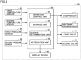
- Fig. 2 is a functional block diagram showing a configuration of air conditioner 100 (Embodiment 1).
- the configuration of controller 50 shown in Fig. 2 is implemented by processor 51 and memory 52 shown in Fig. 1 .
- Controller 50 includes an operation control unit 55, a storage unit 56, a leakage determination unit 57, and a notification unit 58. Controller 50 receives a detection value of first temperature sensor 21, a detection value of second temperature sensor 22, a detection value of first pressure sensor 31, and a detection value of second pressure sensor 32.
- Each of first temperature sensor 21 and second temperature sensor 22 is configured of, for example, a thermistor.
- Each of first pressure sensor 31 and second pressure sensor 32 is configured of, for example, an electronic pressure sensor.
- Operation control unit 55 controls compressor 1, electronic expansion valve 3, first valve 11, and second valve 12. Operation control unit 55 controls an operation frequency of compressor 1, a degree of opening of electronic expansion valve 3, a degree of opening of first valve 11, and a degree of opening of second valve 12 according to a program stored in storage unit 56. Operation control unit 55 receives a start signal and a stop signal transmitted from a remote control or the like. Operation control unit 55 drives compressor 1 upon receipt of the start signal and stops driving of compressor 1 upon receipt of the stop signal.
- Leakage determination unit 57 determines that a refrigerant leakage has occurred in the refrigerant circuit when the refrigerant circuit is partitioned into the first heat exchanger 2 side and the second heat exchanger 4 side by first valve 11 and second valve 12. Leakage determination unit 57 notifies notification unit 58 of a determination result. Notification unit 58 outputs a determination result. For example, notification unit 58 may output a determination result to a display device 60. For example, display device 60 may be mounted in the remote control of air conditioner 100. The user, maintenance personnel, or the like can find the presence or absence of a refrigerant leakage according to the determination result displayed on display device 60.
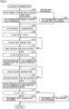
- Fig. 3 is a flowchart showing a procedure for determining a refrigerant leakage (Embodiment 1). The process based on this flowchart is implemented by controller 50.
- controller 50 determines whether it has received a stop signal (step S101).
- the stop signal is a signal for instructing to stop an air-conditioning operation of air conditioner 100.
- the stop signal is transmitted from the remote control of air conditioner 100 to controller 50.
- controller 50 ends the process based on this flowchart.
- controller 50 obtains the ambient temperatures of first heat exchanger 2 and second heat exchanger 4 from first temperature sensor 21 and second temperature sensor 22 (step S102).
- One of first heat exchanger 2 and second heat exchanger 4 is an indoor unit, and the other is an outdoor unit.
- step S102 is a step of obtaining the outdoor and indoor temperatures.
- Controller 50 then performs a leakage determination process (step S103). Controller 50 outputs a determination result after the leakage determination process (step S104). For example, controller 50 outputs the presence or absence of a refrigerant leakage to display device 60 (see Fig. 2 ).
- the leakage determination process (step S103) will be described below in more detail with reference to Fig. 4 .
- Fig. 4 is a flowchart showing the details of the leakage determination process shown in Fig. 3 (Embodiment 1). Controller 50 determines which of first heat exchanger 2 and second heat exchanger 4 has a higher ambient temperature (step S105). Controller 50 performs the determination of step S105 based on the ambient temperatures obtained in step S102 of Fig. 3 .
- Controller 50 sets one of first heat exchanger 2 and second heat exchanger 4, which has a higher ambient temperature, as an examination target for refrigerant leakage (step S106, step S107). In other words, controller 50 sets, as an examination target for refrigerant leakage, one of first heat exchanger 2 and second heat exchanger 4, which has a smaller refrigerant amount when the refrigerant is dispersed, that is, which is gasified more easily.
- Controller 50 then stops driving of compressor 1 (step S108).
- step S108 the refrigerant in the refrigerant circuit is dispersed according to the temperature of the refrigerant circuit. Consequently, a larger amount of refrigerant flows into one of first heat exchanger 2 and second heat exchanger 4, which has a lower ambient temperature.
- Controller 50 may perform step S108 of stopping driving of compressor 1 before the determination of step S105. For example, controller 50 may perform step S108 between step S101 and step S102 of Fig. 3 .
- Controller 50 then closes first valve 11 after the operation frequency of compressor 1 becomes equal to 0 Hz (step S109). Controller 50 then starts counting a first waiting time (step S110) and determines whether the first waiting time has elapsed (step S111). After a lapse of the first waiting time, controller 50 closes second valve 12 (step S112). As first valve 11 and second valve 12 are closed, the refrigerant circuit of air conditioner 100 is partitioned into the first heat exchanger 2 side and the second heat exchanger 4 side. The first waiting time is set to a time required for the refrigerant to be dispersed according to a temperature in the refrigerant circuit.
- Controller 50 then obtains a pressure P1 of the examination target (step 5113).
- pressure P1 is detected by first pressure sensor 31.
- pressure P1 is detected by second pressure sensor 32.
- controller 50 starts counting a second waiting time (step S114).
- Controller 50 determines whether the second waiting time has elapsed (step S115) and counts the second waiting time until the second waiting time has elapsed.
- Controller 50 obtains a pressure P2 of the examination target after a lapse of the second waiting time (step S116).
- Controller 50 determines whether P1 - P2 exceeds a reference value Pth (step S117). When P1 - P2 exceeds reference value Pth, controller 50 determines that the refrigerant has leaked (step S118). When P1 - P2 does not exceed reference value Pth, controller 50 determines that no refrigerant has leaked (step S119). Subsequently, controller 50 ends the process based on this flowchart and proceeds to step S104 of Fig. 3 . In step S104, for example, controller 50 may output a signal for displaying a message "the refrigerant has leaked in first heat exchanger 2" to display device 60 ( Fig. 2 ). The signal may also include the second waiting time and the value of P1 - P2.
- one of first heat exchanger 2 and second heat exchanger 4, which has a smaller refrigerant amount when the refrigerant is dispersed, that is, which has a higher ambient temperature, is set as an examination target for refrigerant leakage.
- inconvenience such as failing to detect a decrease in pressure of the refrigerant in the refrigerant circuit with high accuracy until the pressure of the refrigerant is made equal to the saturation pressure, does not occur.
- air conditioner 100 can be provided that can determine a refrigerant leakage while causing the refrigerant in the refrigerant circuit to be suitable for determination of a refrigerant leakage.
- an imbalance in refrigerant amount is caused to occur in the refrigerant circuit using the phenomenon that the refrigerant flows by itself due to a temperature difference after driving of compressor 1 is stopped.
- Fig. 5 is a refrigerant circuit diagram showing a configuration of an air conditioner 200 according to Embodiment 2.
- air conditioner 100 according to Embodiment 1 is characterized in that a difference in ambient temperature between first heat exchanger 2 and second heat exchanger 4 is used to swiftly determine a refrigerant leakage in a refrigerant circuit. More specifically, air conditioner 100 measures an ambient temperature of first heat exchanger 2 and an ambient temperature of second heat exchanger 4 and checks a decrease in refrigerant pressure in one of the heat exchangers, which has a higher temperature, that is, which has a smaller refrigerant amount, to thereby determine a refrigerant leakage.
- air conditioner 100 according to Embodiment 1 may fail to make full use of the above-mentioned feature when the difference in ambient temperature between first heat exchanger 2 and second heat exchanger 4 is small.
- air conditioner 200 according to Embodiment 2 forces the refrigerant to flow to one of first heat exchanger 2 and second heat exchanger 4 when the difference in ambient temperature between first heat exchanger 2 and second heat exchanger 4 is small.
- air conditioner 200 forces an imbalance in refrigerant amount to occur between first heat exchanger 2 and second heat exchanger 4.
- air conditioner 200 checks a decrease in refrigerant pressure in one of first heat exchanger 2 and second heat exchanger 4, which has a smaller refrigerant amount, to thereby determine a refrigerant leakage.
- Air conditioner 200 will be described below in more detail.
- air conditioner 200 according to Embodiment 2 is different from air conditioner 100 according to Embodiment 1 in that it includes a four-way valve 5.
- Four-way valve 5 is controlled by controller 50.
- Controller 50 switches the state of four-way valve 5 between a first state and a second state to set a target, to which compressor 1 discharges the refrigerant, to first heat exchanger 2 and second heat exchanger 4.
- Fig. 5 shows the state in which the target to which compressor 1 discharges the refrigerant is set to first heat exchanger 2.
- the refrigerant flows in the direction indicated by the arrows in Fig. 5 .
- the first order of circulating the refrigerant is determined by the order of circulating the refrigerant in order of compressor 1, first heat exchanger 2, electronic expansion valve 3, first valve 11, second heat exchanger 4, second valve 12, and compressor 1.
- a second order of circulating the refrigerant is determined by the order of circulating the refrigerant in order of compressor 1, second valve 12, second heat exchanger 4, first valve 11, electronic expansion valve 3, first heat exchanger 2, and compressor 1.
- controller 50 when first heat exchanger 2 is an outdoor unit and second heat exchanger 4 is an indoor unit, controller 50 performs a cooling operation of cooling the interior of a room. Controller 50 switches the state of four-way valve 5 to switch the operation mode from the cooling operation of cooling the interior of a room to a heating operation of heating the interior of a room.
- Fig. 6 is a functional block diagram showing a configuration of air conditioner 200 (Embodiment 2).
- the configuration of air conditioner 200 is different from the configuration of air conditioner 100 shown in Fig. 2 in that four-way valve 5 is added.
- operation control unit 55 is connected to four-way valve 5.
- Operation control unit 55 controls four-way valve 5 to set the target to which compressor 1 discharges the refrigerant to first heat exchanger 2 and second heat exchanger 4.
- the configuration of air conditioner 200 is similar to the configuration of air conditioner 100 except for the configuration of four-way valve 5. Thus, no further description will be repeated.
- Fig. 7 is a refrigerant circuit diagram showing a first pump down operation (Embodiment 2).
- Fig. 8 is a refrigerant circuit diagram showing a second pump down operation (Embodiment 2).
- controller 50 is not shown.
- the pump down operation means an operation of driving a compressor while closing a refrigerant circuit at an outlet of a condenser in the direction in which the refrigerant flows.
- the pump down operation forces the refrigerant in the refrigerant circuit to be collected in the condenser.
- the pump down operation may be performed for, for example, flowing the refrigerant in the refrigerant circuit to the outdoor unit and collecting the refrigerant before air conditioner 200 is relocated.
- Air conditioner 200 uses the pump down operation to force the refrigerant to flow to one of first heat exchanger 2 and second heat exchanger 4. As a result, air conditioner 200 forces an imbalance in refrigerant amount to occur between first heat exchanger 2 and second heat exchanger 4.
- Air conditioner 200 is configured to perform the first pump down operation and the second pump down operation. As shown in Figs. 7 and 8 , the first pump down operation and the second pump down operation will be described by taking, as an example, a case where outdoor unit 201 is configured of first heat exchanger 2 and indoor unit 202 is configured of second heat exchanger 4.
- the first pump down operation is performed to collect the refrigerant in first heat exchanger 2.
- four-way valve 5 is set to the state shown in Fig. 7 .
- first valve 11 is closed, and the second valve is open. In this state, as compressor 1 is driven, high-temperature, high-pressure refrigerant is discharged to first heat exchanger 2.
- controller 50 can effectively determine a refrigerant leakage based on a detection value of second pressure sensor 32.
- the second pump down operation is performed to collect the refrigerant in second heat exchanger 4.
- four-way valve 5 is set to the state shown in Fig. 8 .
- first valve 11 is closed, and the second valve is open. In this state, as compressor 1 is driven, high-temperature, high-pressure refrigerant is discharged to second heat exchanger 4.
- controller 50 can effectively determine a refrigerant leakage based on a detection value of first pressure sensor 31.
- Outdoor unit 201 shown in Figs. 7 and 8 includes first valve 11 and second valve 12.
- indoor unit 202 may be configured to include first valve 11 and second valve 12.
- One of first valve 11 and second valve 12 may be included in outdoor unit 201, and the other may be included in indoor unit 202.
- Fig. 9 is a flowchart showing a procedure for determining a refrigerant leakage (Embodiment 2). The process based on this flowchart is implemented by controller 50.
- controller 50 determines whether it has received a stop signal (step S201).
- the stop signal is a signal for instructing to stop an air-conditioning operation of air conditioner 100.
- the stop signal is transmitted from the remote control of air conditioner 100 to controller 50.
- controller 50 ends the process based on this flowchart.
- controller 50 obtains the ambient temperatures of first heat exchanger 2 and second heat exchanger 4 from first temperature sensor 21 and second temperature sensor 22 (step S202).
- first heat exchanger 2 configures outdoor unit 201
- second heat exchanger 4 configures indoor unit 202.
- step S202 is a step of obtaining the outdoor and indoor temperatures.
- Controller 50 determines whether a temperature difference between the ambient temperature obtained from first temperature sensor 21 and the ambient temperature obtained from second temperature sensor 22 exceeds a threshold Tth (step S203). When determining that the temperature difference exceeds threshold Tth, controller 50 performs a leakage determination process (step S204).
- step S204 The process performed in step S204 is step S105 to step S119 described in Embodiment 1.
- controller 50 cause the refrigerant to disperse by itself in the refrigerant circuit by the technique described in Embodiment 1, thereby causing an imbalance in refrigerant amount in the refrigerant circuit.
- controller 50 checks a decrease in refrigerant pressure in one of first heat exchanger 2 and second heat exchanger 4, which has a higher ambient temperature, that is, which has a smaller refrigerant amount, to thereby determine a refrigerant leakage.
- step S105 to step S119 The details of the process of step S204 have been described as step S105 to step S119, and accordingly, no further description will be repeated.
- controller 50 When determining that the temperature difference does not exceed threshold Tth, controller 50 performs an indoor leakage determination process (step S206) and an outdoor leakage determination process (step S208) and also performs the process of outputting a determination result (step S207, step S209).
- the indoor leakage determination process is a process of determining a refrigerant leakage in second heat exchanger 4 configuring indoor unit 202.
- the indoor leakage determination process includes the first pump down operation for collecting the refrigerant in first heat exchanger 2.
- the details of the indoor leakage determination process are shown in Fig. 10 .
- the outdoor leakage determination process is a process of determining a refrigerant leakage in first heat exchanger 2 configuring outdoor unit 201.
- the outdoor leakage determination process includes the second pump down operation for collecting the refrigerant in second heat exchanger 4.
- the details of the indoor leakage determination process are shown in Fig. 11 .
- Controller 50 outputs a determination result to the outside after the indoor leakage determination process (step S207), and outputs a determination result to the outside after the outdoor leakage determination process (step S209).
- step S207 and step S209 are similar to the process of step S104 described above, and accordingly, description thereof will not be repeated.
- Fig. 10 is a flowchart showing the details of the indoor leakage determination process shown in Fig. 9 (Embodiment 2).
- controller 50 closes first valve 11 (step S211).
- Controller 50 then starts the first pump down operation (step S212).
- four-way valve 5 is set as shown in Fig. 7 and compressor 1 is driven, so that the refrigerant is collected in first heat exchanger 2 of outdoor unit 201.
- Controller 50 then counts a third waiting time (step S213).
- the third waiting time is set to a suitable time as a time required for most of the refrigerant in the refrigerant circuit to flow to first heat exchanger 2.
- Controller 50 determines whether the third waiting time has elapsed (step S214) and counts the third waiting time until the third waiting time has elapsed.
- Controller 50 closes second valve 12 after a lapse of the third waiting time (step S215). Consequently, the refrigerant circuit of air conditioner 200 is partitioned into the first heat exchanger 2 side and the second heat exchanger 4 side. Controller 50 then stops driving of compressor 1 (step S216). As a result, the first pump down operation ends. Since most of the refrigerant is collected in first heat exchanger 2, a large imbalance in refrigerant amount occurs between first heat exchanger 2 and second heat exchanger 4. An amount of the remaining refrigerant is much smaller in second heat exchanger 4 than in first heat exchanger 2. This results in a state in which a refrigerant leakage can be effectively determined based on a detection value of second pressure sensor 32.
- controller 50 obtains pressure P1 of second heat exchanger 4 from second pressure sensor 32 (step S217). Controller 50 starts counting the second waiting time in order to check changes in pressure P1 (step S218). Controller 50 then determines whether the second waiting time has elapsed (step S219) and counts the second waiting time until the second waiting time has elapsed. After a lapse of the second waiting time, controller 50 obtains pressure P2 of second heat exchanger 4 from second pressure sensor 32 (step S220).
- Controller 50 determines whether P1 - P2 exceeds reference value Pth (step S221). When P1 - P2 exceeds reference value Pth, controller 50 determines that the refrigerant has leaked (step S222). When P1 - P2 does not exceed reference value Pth, controller 50 determines that no refrigerant has leaked (step S223). Controller 50 then opens first valve 11 and second valve 12. Subsequently, controller 50 ends the process based on this flowchart and proceeds to step S207 of Fig. 9 . In step S207, for example, controller 50 may output a signal for displaying a message "the refrigerant has leaked in second heat exchanger 4" to display device 60 ( Fig. 2 ). The signal may also include the second waiting time and the value of P1 - P2.
- Fig. 11 is a flowchart showing the details of the outdoor leakage determination process shown in Fig. 9 (Embodiment 2). This flowchart is different from the flowchart of Fig. 10 in that the second pump down operation is performed as the pump down operation and a refrigerant leakage is determined for the refrigerant circuit on the first heat exchanger 2 side.
- the flowchart of Fig. 11 is similar to the flowchart of Fig. 10 except for step S232, step S237, and step S240 of Fig. 11 .
- controller 50 closes first valve 11 (step S231). Controller 50 then starts the second pump down operation (step S232). In the second pump down operation, four-way valve 5 is set as shown in Fig. 8 and compressor 1 is driven, so that the refrigerant is collected in second heat exchanger 4 of indoor unit 202.
- Controller 50 then counts the third waiting time (step S233).
- the third waiting time is set to a suitable time as a time required for most of the refrigerant in the refrigerant circuit to flow to second heat exchanger 4.
- Controller 50 determines whether the third waiting time has elapsed (step S234) and counts the third waiting time until the third waiting time has elapsed.
- Controller 50 closes second valve 12 after a lapse of the third waiting time (step S235). Consequently, the refrigerant circuit of air conditioner 200 is partitioned into the first heat exchanger 2 side and the second heat exchanger 4 side. Controller 50 then stops driving of compressor 1 (step S236). As a result, the second pump down operation ends. Since most of the refrigerant is collected in second heat exchanger 4, a large imbalance in refrigerant amount occurs between first heat exchanger 2 and second heat exchanger 4. An amount of the remaining refrigerant is much smaller in first heat exchanger 2 than in second heat exchanger 4. This results in a state in which a refrigerant leakage can be effectively determined based on a detection value of first pressure sensor 31.
- controller 50 obtains pressure P1 of first heat exchanger 2 from second first pressure sensor 31 (step S237). Controller 50 starts counting the second waiting time in order to check changes in pressure P1 (step S238). Controller 50 then determines whether the second waiting time has elapsed (step S239) and counts the second waiting time until the second waiting time has elapsed. After a lapse of the second waiting time, controller 50 obtains pressure P2 of first heat exchanger 2 from first pressure sensor 31 (step S240).
- Controller 50 determines whether P1 - P2 exceeds reference value Pth (step S241). When P1 - P2 exceeds reference value Pth, controller 50 determines that the refrigerant has leaked (step S242). When P1 - P2 does not exceed reference value Pth, controller 50 determines that no refrigerant has leaked (step S243). Controller 50 then opens first valve 11 and second valve 12 (step S244). Subsequently, controller 50 ends the process based on this flowchart and proceeds to step S209 of Fig. 9 . In step S209, for example, controller 50 may output a signal for displaying a message "the refrigerant has leaked in first heat exchanger 2" to display device 60 ( Fig. 2 ). The signal may also include the second waiting time and the value of P1 - P2.
- air conditioner 200 according to Embodiment 2 can force an imbalance in refrigerant amount to occur between first heat exchanger 2 and second heat exchanger 4 to swiftly determine a refrigerant leakage in the refrigerant circuit as in air conditioner 100 according to Embodiment 1, even when the difference in ambient temperature between first heat exchanger 2 and second heat exchanger 4 is small.
- the first pump down operation and the second pump down operation can be performed using four-way valve 5 to determine a refrigerant leakage in both of outdoor unit 201 and indoor unit 202.
- a refrigerant leakage has occurred in outdoor unit 201 or in indoor unit 202 can be determined. Since a location where a refrigerant leakage has occurred can be determined, a repair suitable for eliminating the refrigerant leakage can be performed more quickly.
- Embodiment 2 In general, when flammable refrigerant is sealed in the refrigerant circuit, it is required to find a refrigerant leakage in an indoor unit earlier than a refrigerant leakage in an outdoor unit.
- the process is performed in order of the indoor leakage determination (step S206) and the outdoor leakage determination (step S208).
- a refrigerant leakage in indoor unit 202 is determined in preference to outdoor unit 201, a refrigerant leakage in the indoor unit can be found earlier than a refrigerant leakage in the outdoor unit.
- Fig. 12 is a refrigerant circuit diagram showing a configuration of an air conditioner 300 (Embodiment 3).
- a decompressor 30 serves as electronic expansion valve 3 and first valve 11 of air conditioner 100 according to Embodiment 1.
- Decompressor 30 expands the refrigerant condensed by first heat exchanger 2 to reduce the pressure of the refrigerant flowing from first heat exchanger 2 to second heat exchanger 4.
- Decompressor 30 closes the refrigerant circuit together with second valve 12 in determination of a refrigerant leakage.
- Decompressor 30 is controlled by controller 50.
- Embodiment 3 can reduce the number of components compared with Embodiment 1.
- Decompressor 30 may be applied to air conditioner 200 according to Embodiment 2.
- Fig. 13 is a flowchart showing a procedure for determining a refrigerant leakage (Embodiment 4).
- the process of the flowchart shown in Fig. 13 is applied to air conditioner 100 described as Embodiment 1.
- air conditioner 100 determines a refrigerant leakage upon receipt of a stop signal.
- air conditioner 100 repeatedly determines a refrigerant leakage while the operation of air conditioner 100 is stopped.
- controller 50 determines whether an operation is stopped or not, that is, whether driving of compressor 1 is stopped or not (step S301). When driving of compressor 1 is not stopped, controller 50 ends the process based on this flowchart. When driving of compressor 1 is stopped, controller 50 starts counting a fourth waiting time (step S302).
- Controller 50 determines whether the fourth waiting time has elapsed (step S303) and counts the fourth waiting time until the fourth waiting time has elapsed. As the fourth waiting time has elapsed, controller 50 obtains the ambient temperatures of first heat exchanger 2 and second heat exchanger 4 from first temperature sensor 21 and second temperature sensor 22 (step S304).
- Controller 50 then performs a leakage determination process (step S305).
- the leakage determination process is similar to the process of the flowchart shown in Fig. 4 . Accordingly, description thereof will not be repeated.
- Controller 50 then outputs a determination result (step S306). This process is similar to step S104 of Fig. 3 . Accordingly, description thereof will not be repeated.
- Controller 50 determines whether it has received a start signal or not (step S307).
- the start signal is transmitted from a remote control or the like when the operation of air conditioner 100 is started.
- controller 50 When no start signal has been received, controller 50 returns the process to step S302. Upon receipt of a start signal, controller 50 ends the process based on this flowchart.
- Embodiment 4 since a refrigerant leakage is determined while the operation is stopped, upon detection of a refrigerant leakage, air conditioner 100 can be repaired using the period in which the operation is stopped.
- Embodiments 1 to 4 have been described in order, Embodiments 1 to 4 may be combined optionally. Modifications will be described below.
- the positions of electronic expansion valve 3 and first valve 11 may be interchanged.
- the ambient temperatures of first heat exchanger 2 and second heat exchanger 4 are measured, and then, first valve 11 and second valve 12 are closed.
- first valve 11 and second valve 12 may be closed, and then, the ambient temperatures of first heat exchanger 2 and second heat exchanger 4 may be measured.
- Embodiment 2 it is desirable particularly in Embodiment 2 that the ambient temperatures of first heat exchanger 2 and second heat exchanger 4 be measured and then first valve 11 and second valve 12 be closed. This is because a temperature difference between the ambient temperature of first heat exchanger 2 and the ambient temperature of second heat exchanger 4 may not exceed a threshold.
- First temperature sensor 21 may be provided at any position of air conditioner 100 as long as it can detect the temperature of the air that exchanges heat with the refrigerant flowing through first heat exchanger 2.
- First temperature sensor 21 is desirably provided in first heat exchanger 2 itself. This is because, for example, if first temperature sensor 21 is provided in the cover or the like that covers first heat exchanger 2, the temperature to be measured may be affected by disturbances.
- second temperature sensor 22 is desirably provided in second heat exchanger 4 itself.
- first valve 11 is closed, and then, second valve 12 is closed.
- second valve 12 may be closed, and then, first valve 11 may be closed.
- an air conditioner can be provided that can determine a refrigerant leakage while causing the refrigerant in the refrigerant circuit to be suitable for determination of a refrigerant leakage.
- the air conditioner further includes a four-way valve (5).
- the four-way valve switches an order in which the refrigerant circulates between a first order and a second order.
- the refrigerant circulates in order of the compressor, the first heat exchanger, the first valve, the second heat exchanger, the second valve, and the compressor.
- the refrigerant circulates in order of the compressor, the second valve, the second heat exchanger, the first valve, the first heat exchanger, and the compressor ( Fig. 7 , Fig. 8 ).
- the first operation is an operation of collecting, when the order in which the refrigerant circulates is set to the first order, the refrigerant in the first heat exchanger by driving the compressor with the first valve closed and then closing the second valve ( Fig. 7 ).
- the second operation is an operation of collecting, when the order in which the refrigerant circulates is set to the second order, the refrigerant in the second heat exchanger by driving the compressor with the first valve closed and then closing the second valve ( Fig. 8 ).
- the controller is configured to perform any one of the first operation and the second operation when a difference between the first temperature and the second temperature is smaller than a threshold (step S203, step S206, step S208), when performing the first operation, determine a refrigerant leakage based on the second pressure after the first operation (step S217 to step S223), and when performing the second operation, determine a refrigerant leakage based on the first pressure after the second operation (step S237 to step S243).
- a refrigerant leakage can be determined while causing the refrigerant in the refrigerant circuit to be suitable for determination of a refrigerant leakage.
- one of the first heat exchanger and the second heat exchanger configures an outdoor unit (201), and the other configures an indoor unit (202).
- the controller is configured to determine a refrigerant leakage that occurs in the indoor unit in preference to determining a refrigerant leakage that occurs in the outdoor unit (step S206, step S208).
- a refrigerant leakage in the outdoor unit is determined in preference to the outdoor unit, and thus, a refrigerant leakage in the indoor unit can be found earlier.
- the controller is configured to output a signal for notifying a determination result of a refrigerant leakage (58).
- a determination result of a refrigerant leakage can be determined.
- the controller is configured to close the first valve and close the second valve upon receipt of a stop signal for instructing to stop driving of the compressor (step S108 to step S112).
- a refrigerant leakage can be determined while the operation of the air conditioner is stopped.
- the controller is configured to close one of the first valve and the second valve, and after a lapse of a reference time, close the other (step S109 to step S112).
- the time in which the refrigerant flows according to the difference between the temperature of the first heat exchanger and the temperature of the second heat exchanger can be secured.
- the controller is configured to determine the first temperature and the second temperature, and then close the first valve and close the second valve (step S105, step S109 to step S112).
- a first circulation path can be closed with the determination that there is a sufficient difference between a detection value of the first temperature sensor and a detection value of the second temperature sensor.
- the second valve is configured of a decompressor (30) configured to reduce a pressure of the refrigerant flowing from the first heat exchanger to the second heat exchanger in the refrigerant circuit.
Landscapes
- Engineering & Computer Science (AREA)
- Mechanical Engineering (AREA)
- General Engineering & Computer Science (AREA)
- Chemical & Material Sciences (AREA)
- Combustion & Propulsion (AREA)
- Physics & Mathematics (AREA)
- Thermal Sciences (AREA)
- Air Conditioning Control Device (AREA)
Applications Claiming Priority (1)
| Application Number | Priority Date | Filing Date | Title |
|---|---|---|---|
| PCT/JP2021/041927 WO2023084779A1 (ja) | 2021-11-15 | 2021-11-15 | 空気調和機 |
Publications (1)
| Publication Number | Publication Date |
|---|---|
| EP4435338A1 true EP4435338A1 (de) | 2024-09-25 |
Family
ID=86335473
Family Applications (1)
| Application Number | Title | Priority Date | Filing Date |
|---|---|---|---|
| EP21964132.1A Withdrawn EP4435338A1 (de) | 2021-11-15 | 2021-11-15 | Klimaanlage |
Country Status (5)
| Country | Link |
|---|---|
| US (1) | US20240418382A1 (de) |
| EP (1) | EP4435338A1 (de) |
| JP (1) | JPWO2023084779A1 (de) |
| CN (1) | CN118215806A (de) |
| WO (1) | WO2023084779A1 (de) |
Families Citing this family (1)
| Publication number | Priority date | Publication date | Assignee | Title |
|---|---|---|---|---|
| EP4455579A4 (de) * | 2021-12-22 | 2025-11-05 | Toshiba Carrier Corp | Klimaanlage |
Family Cites Families (18)
| Publication number | Priority date | Publication date | Assignee | Title |
|---|---|---|---|---|
| JPH04369370A (ja) * | 1991-06-14 | 1992-12-22 | Hitachi Ltd | 冷凍装置 |
| JP3126266B2 (ja) * | 1993-06-18 | 2001-01-22 | 三菱電機株式会社 | 空気調和装置 |
| JP3733674B2 (ja) | 1997-01-30 | 2006-01-11 | 株式会社デンソー | 空調装置 |
| JP2005241050A (ja) * | 2004-02-24 | 2005-09-08 | Mitsubishi Electric Building Techno Service Co Ltd | 空調システム |
| JP4548502B2 (ja) * | 2008-03-24 | 2010-09-22 | 三菱電機株式会社 | 冷凍装置 |
| CN203274347U (zh) * | 2013-04-28 | 2013-11-06 | 钟飞 | 自动变量式多用途空调以及冷热水装置 |
| JP6521571B2 (ja) * | 2014-04-18 | 2019-05-29 | 日立ジョンソンコントロールズ空調株式会社 | 冷温熱機器 |
| GB2566201B (en) * | 2016-07-15 | 2021-02-24 | Mitsubishi Electric Corp | Air-conditioning apparatus |
| JP6647406B2 (ja) * | 2016-07-29 | 2020-02-14 | 三菱電機株式会社 | 冷凍サイクル装置 |
| US11181303B2 (en) * | 2016-11-22 | 2021-11-23 | Mitsubishi Electric Corporation | Air-conditioning apparatus and air-conditioning system |
| JP6804631B2 (ja) * | 2017-03-13 | 2020-12-23 | 三菱電機株式会社 | 冷凍サイクル装置 |
| JP7002227B2 (ja) * | 2017-06-14 | 2022-01-20 | 日立ジョンソンコントロールズ空調株式会社 | 空気調和機 |
| ES2943107T3 (es) * | 2018-07-06 | 2023-06-09 | Mitsubishi Electric Corp | Dispositivo de ciclo de refrigeración |
| JP7413896B2 (ja) * | 2020-03-31 | 2024-01-16 | 株式会社富士通ゼネラル | 空気調和装置 |
| CN111486612A (zh) * | 2020-04-29 | 2020-08-04 | 广东美的暖通设备有限公司 | 多联机系统及其制热阀泄漏检测方法、装置和存储介质 |
| CN111503948A (zh) * | 2020-04-29 | 2020-08-07 | 广东美的暖通设备有限公司 | 多联机系统及其制冷阀泄漏检测方法、装置和存储介质 |
| US11131471B1 (en) * | 2020-06-08 | 2021-09-28 | Emerson Climate Technologies, Inc. | Refrigeration leak detection |
| CN114857741B (zh) * | 2022-05-20 | 2024-05-28 | 江苏科技大学 | 一种具有故障诊断和应急启动的空调系统及其控制方法 |
-
2021
- 2021-11-15 EP EP21964132.1A patent/EP4435338A1/de not_active Withdrawn
- 2021-11-15 WO PCT/JP2021/041927 patent/WO2023084779A1/ja not_active Ceased
- 2021-11-15 JP JP2023559385A patent/JPWO2023084779A1/ja not_active Withdrawn
- 2021-11-15 US US18/701,775 patent/US20240418382A1/en active Pending
- 2021-11-15 CN CN202180104077.1A patent/CN118215806A/zh active Pending
Also Published As
| Publication number | Publication date |
|---|---|
| US20240418382A1 (en) | 2024-12-19 |
| WO2023084779A1 (ja) | 2023-05-19 |
| JPWO2023084779A1 (de) | 2023-05-19 |
| CN118215806A (zh) | 2024-06-18 |
Similar Documents
| Publication | Publication Date | Title |
|---|---|---|
| US11578887B2 (en) | HVAC system leak detection | |
| CN107084494B (zh) | 电子膨胀阀的故障检测方法、检测装置和多联式空调系统 | |
| EP3680585B1 (de) | Klimatisierungsvorrichtung | |
| CN100549573C (zh) | 空气调节器及其制冷剂量判定方法 | |
| EP2233862A2 (de) | Klima- und Energieanlage | |
| JP6121075B1 (ja) | 冷凍サイクル装置 | |
| CN104136858B (zh) | 空气调节机 | |
| EP2204621A2 (de) | Klimaanlage und Verfahren zur Erkennung der Fehlfunktion davon | |
| EP2239518A2 (de) | Klimaanlage | |
| WO2019239556A1 (ja) | 空気調和装置 | |
| KR20140056965A (ko) | 공기조화기 및 그 제어 방법 | |
| EP3441689B1 (de) | Klimaanlage | |
| CN109073306B (zh) | 制冷循环装置 | |
| CN102062458A (zh) | 空调压缩机故障判断和控制停机的方法 | |
| KR20110001667A (ko) | 공기조화기 및 그 동작방법 | |
| EP2639516A2 (de) | Hydronischer Wärmepumpenheizer | |
| JPWO2017002214A1 (ja) | 冷凍サイクルシステム | |
| EP2416078A1 (de) | Klimaanlage | |
| CN108603681B (zh) | 冷气机以及空气调节机 | |
| EP3130868A1 (de) | Wärmepumpensystem | |
| US12209782B2 (en) | Abnormality determination device, freezing device including this abnormality determination device, and abnormality determination method for compressor | |
| EP4435338A1 (de) | Klimaanlage | |
| US12359836B2 (en) | Air-conditioning apparatus, and air discharge method for air-conditioning apparatus | |
| JP3915819B2 (ja) | 空気調和装置 | |
| KR20100136004A (ko) | 동파방지 기능을 구비한 히트펌프 시스템 |
Legal Events
| Date | Code | Title | Description |
|---|---|---|---|
| STAA | Information on the status of an ep patent application or granted ep patent |
Free format text: STATUS: THE INTERNATIONAL PUBLICATION HAS BEEN MADE |
|
| PUAI | Public reference made under article 153(3) epc to a published international application that has entered the european phase |
Free format text: ORIGINAL CODE: 0009012 |
|
| STAA | Information on the status of an ep patent application or granted ep patent |
Free format text: STATUS: REQUEST FOR EXAMINATION WAS MADE |
|
| STAA | Information on the status of an ep patent application or granted ep patent |
Free format text: STATUS: THE APPLICATION HAS BEEN WITHDRAWN |
|
| 17P | Request for examination filed |
Effective date: 20240509 |
|
| AK | Designated contracting states |
Kind code of ref document: A1 Designated state(s): AL AT BE BG CH CY CZ DE DK EE ES FI FR GB GR HR HU IE IS IT LI LT LU LV MC MK MT NL NO PL PT RO RS SE SI SK SM TR |
|
| 18W | Application withdrawn |
Effective date: 20240830 |