EP4434650A1 - Biegevorrichtung - Google Patents
Biegevorrichtung Download PDFInfo
- Publication number
- EP4434650A1 EP4434650A1 EP23162871.0A EP23162871A EP4434650A1 EP 4434650 A1 EP4434650 A1 EP 4434650A1 EP 23162871 A EP23162871 A EP 23162871A EP 4434650 A1 EP4434650 A1 EP 4434650A1
- Authority
- EP
- European Patent Office
- Prior art keywords
- bending
- die
- receiving space
- bending device
- displacement
- Prior art date
- Legal status (The legal status is an assumption and is not a legal conclusion. Google has not performed a legal analysis and makes no representation as to the accuracy of the status listed.)
- Pending
Links
- 238000005452 bending Methods 0.000 title claims abstract description 144
- 238000006073 displacement reaction Methods 0.000 claims abstract description 61
- 238000009413 insulation Methods 0.000 claims abstract description 33
- 238000000034 method Methods 0.000 claims abstract description 16
- 230000007704 transition Effects 0.000 claims description 9
- 244000089486 Phragmites australis subsp australis Species 0.000 description 2
- 230000001419 dependent effect Effects 0.000 description 2
- 239000011159 matrix material Substances 0.000 description 2
- 239000002184 metal Substances 0.000 description 2
- 239000002131 composite material Substances 0.000 description 1
- 230000003247 decreasing effect Effects 0.000 description 1
- 239000006260 foam Substances 0.000 description 1
- 239000000463 material Substances 0.000 description 1
- XLYOFNOQVPJJNP-UHFFFAOYSA-N water Substances O XLYOFNOQVPJJNP-UHFFFAOYSA-N 0.000 description 1
Images

Classifications
-
- B—PERFORMING OPERATIONS; TRANSPORTING
- B21—MECHANICAL METAL-WORKING WITHOUT ESSENTIALLY REMOVING MATERIAL; PUNCHING METAL
- B21D—WORKING OR PROCESSING OF SHEET METAL OR METAL TUBES, RODS OR PROFILES WITHOUT ESSENTIALLY REMOVING MATERIAL; PUNCHING METAL
- B21D7/00—Bending rods, profiles, or tubes
- B21D7/02—Bending rods, profiles, or tubes over a stationary forming member; by use of a swinging forming member or abutment
- B21D7/022—Bending rods, profiles, or tubes over a stationary forming member; by use of a swinging forming member or abutment over a stationary forming member only
-
- B—PERFORMING OPERATIONS; TRANSPORTING
- B29—WORKING OF PLASTICS; WORKING OF SUBSTANCES IN A PLASTIC STATE IN GENERAL
- B29C—SHAPING OR JOINING OF PLASTICS; SHAPING OF MATERIAL IN A PLASTIC STATE, NOT OTHERWISE PROVIDED FOR; AFTER-TREATMENT OF THE SHAPED PRODUCTS, e.g. REPAIRING
- B29C53/00—Shaping by bending, folding, twisting, straightening or flattening; Apparatus therefor
- B29C53/02—Bending or folding
- B29C53/08—Bending or folding of tubes or other profiled members
- B29C53/083—Bending or folding of tubes or other profiled members bending longitudinally, i.e. modifying the curvature of the tube axis
-
- B—PERFORMING OPERATIONS; TRANSPORTING
- B21—MECHANICAL METAL-WORKING WITHOUT ESSENTIALLY REMOVING MATERIAL; PUNCHING METAL
- B21D—WORKING OR PROCESSING OF SHEET METAL OR METAL TUBES, RODS OR PROFILES WITHOUT ESSENTIALLY REMOVING MATERIAL; PUNCHING METAL
- B21D28/00—Shaping by press-cutting; Perforating
- B21D28/24—Perforating, i.e. punching holes
- B21D28/26—Perforating, i.e. punching holes in sheets or flat parts
-
- B—PERFORMING OPERATIONS; TRANSPORTING
- B21—MECHANICAL METAL-WORKING WITHOUT ESSENTIALLY REMOVING MATERIAL; PUNCHING METAL
- B21D—WORKING OR PROCESSING OF SHEET METAL OR METAL TUBES, RODS OR PROFILES WITHOUT ESSENTIALLY REMOVING MATERIAL; PUNCHING METAL
- B21D28/00—Shaping by press-cutting; Perforating
- B21D28/24—Perforating, i.e. punching holes
- B21D28/32—Perforating, i.e. punching holes in other articles of special shape
- B21D28/325—Perforating, i.e. punching holes in other articles of special shape using cam or wedge mechanisms, e.g. aerial cams
Definitions
- the present invention relates to a bending device for bending pipes having an insulating jacket according to claim 1 and an actuating arrangement for actuating two dies according to claim 13.
- Pipe bending devices have become known from the state of the art.
- the US$8,375,764 a bending device for a pipe so that the pipe can be bent by an angle of, for example, 90°.
- Pipes for water pipes that are covered by an insulating jacket are known from the state of the art.
- the bending device according to the US$8,375,764 has the disadvantage that such pipes cannot be bent or can only be bent with a loss of quality.
- the present invention is based on the object of specifying a bending device for bending a pipe with an insulating jacket, which overcomes the disadvantages of the prior art.
- it is a particularly preferred object to specify a bending device for a pipe with an insulating jacket, with which the pipe can be bent without problems, in particular without kinks.
- a bending device for bending a pipe with an insulation jacket a bending die arrangement with at least one bending die.
- the at least one bending die provides a receiving space partially delimited by side walls, which receiving space has an access opening through which the pipe with the insulation jacket can be inserted into the receiving space for the bending process.
- At least one bending surface is arranged in the receiving space, which extends partially around a central axis.
- at least one displacement recess is arranged in such a way that it enlarges the receiving space, so that the insulation jacket can be displaced into the displacement recess during the bending process.
- the possibility of displacing the insulation jacket into the displacement recess ensures that the pipe rests against the bending surface with a minimal insulation jacket volume, thereby ensuring that the pipe can be bent without negative influence, in particular without kinking.
- a further advantage is that the displacement of the insulation jacket means that the insulation jacket is treated gently.
- the bending surface can have a certain width or can be very narrow, in which case the bending surface is a bending edge.
- the bending surface preferably extends over an arc segment of 90° around the central axis. Depending on the application, larger or smaller angles are also conceivable.
- the bending surface can run parallel or at an angle to the central axis.
- the cross section of the at least one displacement recess when the pipe is inserted has an area of 60% to 120% of the area of the receiving space between the inserted pipe and the access opening.
- the displacement recess extends along the bending surface.
- the displacement recess and the bending surface run essentially parallel to one another.
- the displacement recess can be located directly next to the bending surface or at a distance from the bending surface as seen in the direction of the central axis.
- the bending surface of the displacement recess is connected via a convex curve.
- the convex curve is designed in such a way that a gentle Transition from the bending surface to the displacement recess can be provided.
- two or more bending surfaces are arranged parallel to each other. This ensures that the pipe is optimally supported in the holder and the force generated during the bending process can be distributed over a larger area.
- two or more displacement recesses are arranged. This allows the spatial area into which the insulation jacket can be displaced to be increased.
- one displacement recess is arranged per bending surface.
- one bending surface and one displacement recess form a pair, with preferably two pairs being arranged.
- At least one bending surface is arranged between two displacement recesses spaced apart from one another, viewed transversely to the central axis.
- two bending surfaces are located between the two displacement recesses.
- the two bending surfaces are oriented at an angle to the central axis.
- the bending surfaces are positioned relative to one another in such a way that a V-shaped receptacle can be created.
- the receiving space has an upper side wall, as viewed from the access opening, a lower side wall spaced apart from the upper side wall, and a rear wall closing off the receiving space towards the rear and located opposite the access opening.
- the displacement recess extends, as viewed from the receiving space, into the upper side wall and/or the lower side wall and/or the rear wall.
- the bending surface is preferably part of the rear wall.
- the displacement recess extends from the receiving space into the bending die.
- the displacement recess extends in cross section along the central axis in a first section as a conical surface segment and in a second section as a rounded surface segment.
- the spatial area can be optimally enlarged by the rounded surface segment.
- the bending die is formed in two parts with a first die part and a second die part.
- the first die part lies on one side of an imaginary plane and the second die part lies on another side of the imaginary plane.
- the imaginary plane extends perpendicular to the central axis and centrally through the receiving space.
- each die part has the at least one bending surface; wherein either each die part has the at least one displacement recess, or wherein only one of the two die parts has the at least one displacement recess.
- only one of the two die parts has the at least one displacement recess; wherein either each die part has the at least one bending surface, or wherein only one of the two die parts has the at least one bending surface.
- the two die parts are connected to one another via a guide structure so that they can move relative to one another.
- the two die parts can be moved towards one another via an actuating arrangement with an actuating element, wherein the guide structure preferably has a return element which pushes the two die parts away from one another.
- the die parts are in an initial position before the pipe is inserted into the receiving space and the two die parts are moved towards each other into a bending position before the bending process, such that the insulation of the inserted pipe is partially compressed and partially pressed into the displacement recess and that the pipe is clamped by the die parts.
- the die parts are spaced apart from each other in the bending position or can be brought into contact with each other via contact surfaces.
- the distance between the two die parts depends essentially on the diameter of the pipe. With a minimum pipe diameter, the two die parts can be moved "to block” in the bending position so that the two die parts can be brought into contact with each other via the contact surfaces. Contact are.
- the actuating arrangement for the bending device described herein comprises a bearing rod extending along a bearing rod axis, which is connected to the first die part via a bearing section and extends through an opening on the second die part, and a pivot rod extending along a pivot rod axis and which is arranged on the bearing rod opposite the bearing section.
- the pivot rod axis runs at right angles to the bearing rod axis.
- the said actuating element is pivotally connected to the pivot rod.
- the actuating element has a contact surface with which the actuating element acts on an actuator surface on the second die part, wherein the contact surface has at least two surface segments, the distance of which from the pivot rod axis is different in each case, such that when one surface segment is in contact with the actuator surface, the distance between the die parts is different than when another of the surface segments is in contact with the actuator surface.
- An actuating arrangement for providing movement between a first die part and a second die part is specified in claim 13.
- the actuating arrangement according to claim 13 comprises a bearing rod extending along a bearing rod axis, which is connected to the first die part via a bearing section and extends through an opening in the second die part, and a pivot rod extending along a pivot rod axis and which is arranged on the bearing rod opposite the bearing section.
- the pivot rod axis runs perpendicular to the bearing rod axis.
- the said actuating element is pivotally connected to the pivot rod.
- the actuating element has a contact surface with which the actuating element acts on an actuator surface on the second die part, wherein the contact surface has at least two surface segments, the distance from the pivot rod axis of which is different in each case, such that when one surface segment is in contact with the actuator surface, the distance between the die parts is different than when another of the surface segments is in contact with the actuator surface.
- the actuating element has a lever section.
- the lever section extends essentially transversely away from the pivot rod axis.
- the surface segments can be designed as flat or rounded surface segments.
- a transition surface is arranged between the surface segments, wherein the transition surface is rounded with a curve.
- the curve is designed such that the distance between the curve and the pivot rod axis preferably changes continuously between the two surface segments.
- the actuating element has at least one marking which, when the actuating element is in the appropriate position, specifies the distance between the two die parts.
- the figures show a bending device 1 according to an embodiment of the present invention.
- the figures also show an actuating arrangement 17.
- the bending device 1 can be designed with the actuating arrangement 17. Both the actuating arrangement 17 and the bending device 1 can be designed independently of one another.
- the actuating arrangement 17 can be used in other devices not shown here, and the bending device 1 can be actuated with other actuating arrangements not shown here.
- the bending device 1 is used to bend a pipe R with an insulation jacket I.
- the pipe R is typically made of metal or a composite material with metal and plastic.
- the insulation jacket I is made of foam.
- the insulation jacket I surrounds the outside of the pipe R and typically extends over its entire length.
- Bending device 1 comprises a bending die arrangement 2 with at least one bending die 3.
- the bending die 3 comprises two die parts, namely a first die part 14 and a second die part 15.
- the bending die consists of only one die part.
- the bending die 3 provides a receiving space 6 partially delimited by side walls 4, 5.
- the receiving space 6 has an access opening 7 through which the pipe R with the insulation jacket I can be inserted into the receiving space 6 for the bending process.
- At least one bending surface 8 is arranged in the receiving space 6, which extends partially around a central axis M.
- the pipe R with the insulation jacket I is bent around the bending surface 8.
- the bending surface extends around the central axis M by an angle of at least 90°, in particular of at least 100°.
- the angle is essentially dependent on the desired pipe bending angle. Depending on the material of the pipe, the angle must be slightly larger than the pipe bending angle, because the pipe can spring back after the bending process has taken place.
- the bending die 8 comprises at least one displacement recess 9.
- the at least one displacement recess 9 is arranged such that it enlarges the receiving space 6 so that the insulation jacket I can be displaced into the displacement recess 9 during the bending process.
- the displacement of the insulation jacket I is shown accordingly.
- the pipe R in the Figures 5a, 5b has a larger diameter than the pipe R in the Figures 8a, 8b .
- the insulation jacket I is displaced into the at least one displacement recess 9. This means that the insulation jacket I flows into the at least one displacement recess 9.
- the pipe R lies indirectly on the bending surface 8 via the insulation jacket I, with the insulation jacket I being compressed at this point.
- the insulation jacket I not only extends into the at least one displacement recess 9, but is also displaced outwards via the access opening 7.
- the at least one displacement recess 9 extends along the at least one bending surface 8. This means that the at least one displacement recess 9 is located adjacent to the bending surface 8. In the embodiment shown, the displacement recess 9 merges with the bending surface 8 via a convex curve 10. In the embodiment shown, two bending surfaces 8 and two displacement recesses 9 are arranged. The two bending surfaces 8 are located between the two displacement recesses 9.
- the receiving space 6 has, as seen from the access opening 7, an upper side wall 4, a lower side wall 5 located at a distance from the upper side wall 4, and a rear wall 11 which closes off the receiving space 6 towards the rear and is located opposite the access opening 7.
- the two side walls 4, 5 extend from the access opening 7 to the rear wall 11.
- the displacement recesses 9 extend, as seen from the receiving space 6, into the respective side wall 4, 5 and into the rear wall 11.
- the displacement recesses 9 are located in the region of the transition from the side wall 4, 5 to the rear wall 11.
- the bending surface 11 is also located on the rear wall 11 or, depending on the design of the bending surface 11, the bending surface 11 is provided by the rear wall.
- the displacement recess 9 extends here in cross section along the central axis in a first section 12 as a conical surface segment and in a second section 13 extends as a rounded surface segment.
- the conical surface segment is positioned such that the clear width between the two displacement recesses 9 increases with increasing depth from the access opening 7 into the receiving space 6.
- the rounded surface segment is designed as a concave curve. The rounded surface segment merges with the convex curve 10 to the bending surface 8.
- the receiving space 6 has a cross-section, as seen from the access opening 7, which is constant up to the beginning of the first section and then widens due to the displacement recess 9. Due to the constant cross-section, the pipe R with the insulation jacket I can be easily guided along the bending surface 8 during the bending process. The pipe R slides further into the receiving space 6 with increasing degree of bending.
- the cross-section of the displacement recess 9 is substantially constant over its entire length around the central axis M.
- the displacement recess 9 preferably runs in such a way that its cross-section becomes continuously smaller with decreasing distance from the beginning or the end.
- the bending die 3 is designed in two parts with a first die part 14 and a second die part 15.
- the two die parts 14, 15 can be moved from a starting position to a bending position towards each other and then moved away from each other again from the bending position to the starting position.
- the starting position is shown.
- the pipe R with the insulation jacket I can be inserted into the receiving space 6 via the access opening 7.
- the two die parts are then moved into the bending position and the pipe R can be bent.
- the insulation jacket I is continuously displaced into the displacement recess 9.
- the first die part 14 lies on one side of an imaginary plane E and the second die part 15 lies on another side of the imaginary plane E.
- the imaginary plane E extends at right angles to the central axis M and centrally through the receiving space 6.
- each die part 14, 15 has a bending surface 8 and a displacement recess 9.
- the two die parts 14, 15 are connected to one another via a guide structure 16.
- the guide structure 16 here has several guide pins via which the die parts 14, 15 are connected.
- the upper die part 14 is movable with respect to the guide pins, and the lower die part 15 is fixedly mounted to the guide pins.
- the two die parts 14, 15 can be moved towards one another from the starting position into the bending position via an actuating arrangement 17 with an actuating element 18. Furthermore, the guide structure 16 preferably has a return element 19 which pushes the two die parts 14, 15 away from one another. When the actuation with the actuating element 18 is no longer used, the two die parts 14, 15 are returned to the starting position by the return element 19. As mentioned, the die parts 14, 15 are in the starting position before the pipe R is inserted into the receiving space 6, and the die parts 14, 15 are moved towards one another into the bending position before the bending process, such that the insulation I of the inserted pipe R is partially compressed and partially pressed into the displacement recess, and that the pipe R is held by the die parts 14, 15.
- the die parts 14, 15 are positioned relative to each other depending on the pipe diameter.
- the die parts 14, 15 are spaced apart from one another in the bending position and, with the smaller diameter, the two die parts 14, 15 are in contact with one another in the bending position via contact surfaces 20.
- the actuating arrangement 17 comprises a bearing rod 21 which extends along a bearing rod axis L and is connected to the first die part 14 via a bearing section 22 and extends through an opening 23 on the second die part 15, and a pivot rod 24 which extends along a pivot rod axis S and which is arranged on the bearing rod 21 opposite the bearing section 22.
- the pivot rod axis S is perpendicular to the bearing rod axis L.
- the actuating element 18 is pivotably connected to the pivot rod 24.
- the actuating element 18 has an opening 32 into which the pivot rod 24 projects.
- the actuating element 18 has a contact surface 25. With the contact surface 15, the actuating element 18 acts on an actuator surface 26 on the second die part 15.
- the contact surface 25 has at least two surface segments 27, 28, the distance of which from the pivot rod axis S is different, such that when one surface segment 27 is in contact with the actuator surface 26, the distance between the die parts 14, 15 is different than when another of the surface segments 28 is in contact with the actuator surface 26. This is due to the Figures 5a and 8a clearly visible.
- the actuating element 18 has a lever portion 29.
- the lever portion 29 can be grasped by a user and pivoted about the pivot axis S.
- the surface segments 27, 28 are designed as flat surface segments.
- a design as rounded surface segments is also conceivable.
- a transition surface 30 is arranged between the surface segments 27, 28, wherein the transition surface 30 is rounded with a curve, wherein the curve is formed such that the distance between the curve and the pivot rod axis S preferably changes continuously between the two surface segments 27, 28.
- the actuating element 18 has at least one marking 31 which, when the actuating element 18 is in a corresponding position, specifies the distance between the two die parts 14, 15.
Landscapes
- Engineering & Computer Science (AREA)
- Mechanical Engineering (AREA)
- Bending Of Plates, Rods, And Pipes (AREA)
Abstract
Eine Biegevorrichtung (1) zur Biegung von einem Rohr (R) mit einem Isolationsmantel (I), umfassend eine Biegematrizenanordnung (2) mit mindestens einer Biegematrize (3),wobei die mindestens eine Biegematrize (3) einen mit Seitenwänden (4, 5) teilweise begrenzten Aufnahmeraum (6) bereitstellt, welcher Aufnahmeraum (6) eine Zugangsöffnung (7) aufweist, über welche das Rohr (R) mit dem Isolationsmantel (I) in den Aufnahmeraum (6) für den Biegevorgang einlegbar ist,wobei mindestens eine Biegefläche (8) im Aufnahmeraum (6) angeordnet ist, welche sich um eine Mittelachse (M) teilweise herum erstreckt, undwobei mindestens eine Verdrängungsausnehmung (9) derart angeordnet ist, dass diese den Aufnahmeraum (6) vergrössert, so dass der Isolationsmantel (I) beim Biegevorgang in die Verdrängungsausnehmung (9) verdrängbar ist.
Description
- Die vorliegende Erfindung betrifft eine Biegevorrichtung zum Biegen von Rohren, die einen Isolationsmantel aufweisen, nach Anspruch 1 und eine Betätigungsanordnung zur Betätigung von zwei Matrizen nach Anspruch 13.
- Aus dem Stand der Technik sind Rohrbiegevorrichtungen bekannt geworden. Beispielsweise offenbart die
US 8,375,764 eine Biegevorrichtung für ein Rohr, so dass das Rohr um einen Winkel von beispielsweise 90° gebogen werden kann. - Aus dem Stand der Technik sind Rohre für Wasserleitungen bekannt geworden, welche durch einen Isolationsmantel umhüllt werden. Die Biegevorrichtung nach der
US 8,375,764 weist den Nachteil auf, dass derartige Rohre nicht oder nur mit Qualitätseinbussen gebogen werden können. - Ausgehend von diesem Stand der Technik liegt der vorliegenden Erfindung eine Aufgabe zugrunde, eine Biegevorrichtung zur Biegung von einem Rohr mit einem Isolationsmantel anzugeben, welche die Nachteile des Standes der Technik überwindet. Insbesondere ist es eine besonders bevorzugte Aufgabe, eine Biegevorrichtung für ein Rohr mit einem Isolationsmantel anzugeben, mit welcher das Rohr störungsfrei, insbesondere knickfrei, gebogen werden kann.
- Diese Aufgabe und andere Aufgaben löst der Gegenstand nach Anspruch 1. Demgemäss umfasst eine Biegevorrichtung zur Biegung von einem Rohr mit einem Isolationsmantel, eine Biegematrizenanordnung mit mindestens einer Biegematrize. Die mindestens eine Biegematrize stellt einen teilweise mit Seitenwänden begrenzten Aufnahmeraum bereit, welcher Aufnahmeraum eine Zugangsöffnung aufweist, über welche das Rohr mit dem Isolationsmantel in den Aufnahmeraum für den Biegevorgang einlegbar ist. Mindestens eine Biegefläche ist im Aufnahmeraum angeordnet, welche sich um eine Mittelachse teilweise herum erstreckt. Weiterhin ist mindestens eine Verdrängungsausnehmung derart angeordnet, dass diese den Aufnahmeraum vergrössert, so dass der Isolationsmantel beim Biegevorgang in die Verdrängungsausnehmung verdrängbar ist.
- Durch die Möglichkeit der Verdrängung des Isolationsmantels in die Verdrängungsausnehmung wird sichergestellt, dass das Rohr mit einem minimalen Isolationsmantelvolumen an der Biegefläche anliegt, wodurch sichergestellt wird, dass das Rohr ohne negative Einwirkung, insbesondere knickfrei, gebogen werden kann.
- Ein weiterer Vorteil ist, dass durch die Verdrängung des Isolationsmantel, der Isolationsmantel schonend behandelt wird.
- Die Biegefläche kann eine gewisse Breite aufweisen oder aber sehr schmal ausgebildet sein, wobei dann die Biegefläche eine Biegekante ist. Die Biegefläche erstreckt sich vorzugsweise um ein Bogensegment von 90° um die Mittelachse. Je nach Anwendung sind grössere oder kleinere Winkel auch denkbar.
- Die Biegefläche kann parallel oder winklig geneigt zur Mittelachse verlaufen.
- Vorzugsweise weist der Querschnitt der mindestens einen Verdrängungsausnehmung bei eingelegtem Rohr eine Fläche von 60% bis 120% von der Fläche des Aufnahmeraums zwischen dem eingelegten Rohr und der Zugangsöffnung auf.
- Vorzugsweise erstreckt sich die Verdrängungsausnehmung entlang der Biegefläche. Mit anderen Worten gesagt verlaufen die Verdrängungsausnehmung und die Biegefläche im Wesentlichen parallel zueinander. Die Verdrängungsausnehmung kann dabei direkt neben der Biegefläche liegen oder in einem in Richtung der Mittelachse gesehen Abstand beanstandet zur Biegefläche.
- Vorzugsweise schliesst sich die Biegefläche der Verdrängungsausnehmung über eine konvexe Rundung an. Die konvexe Rundung ist derart ausgebildet, dass ein sanfter Übergang von der Biegefläche zur Verdrängungsausnehmung bereitgestellt werden kann.
- Vorzugsweise sind zwei oder mehr Biegeflächen parallel zueinander angeordnet. Hierdurch wird das Rohr optimal in der Aufnahme abgestützt und die Kraft, die beim Biegevorgang entsteht, kann über eine grössere Fläche verteilt werden.
- Vorzugsweise sind zwei oder mehr Verdrängungsausnehmungen angeordnet. Hierdurch kann der Raumbereich, in welchen der Isolationsmantel verdrängt werden kann, vergrössert werden.
- Vorzugsweise ist pro Biegefläche eine Verdrängungsausnehmung angeordnet. In einer besonders bevorzugten Ausführungsform bilden jeweils eine Biegefläche und eine Verdrängungsausnehmung ein Paar, wobei vorzugsweise zwei Paare angeordnet sind.
- Vorzugsweise ist quer zur Mittelachse gesehen mindestens eine Biegefläche zwischen zwei beabstandet zueinander liegenden Verdrängungsausnehmungen angeordnet.
- Vorzugsweise liegen zwei Biegeflächen zwischen den beiden Verdrängungsausnehmungen. Besonders bevorzugt sind die beiden Biegeflächen winklig geneigt zur Mittelachse orientiert. Die Biegeflächen liegen dabei derart zueinander, dass eine V-förmige Aufnahme geschaffen werden kann.
- Vorzugsweise weist der Aufnahmeraum von der Zugangsöffnung her gesehen eine obere Seitenwand, eine beabstandet zur oberen Seitenwand liegende untere Seitenwand, und einen den Aufnahmeraum nach hinten hin abschliessende und gegenüber der Zugangsöffnung liegende Rückwand auf. Die Verdrängungsausnehmung erstreckt sich vom Aufnahmeraum her gesehen in die obere Seitenwand und/oder die untere Seitenwand und/oder die Rückwand hinein. Die Biegefläche ist vorzugsweise Teil der Rückwand.
- Mit anderen Worten gesagt erstreckt sich die Verdrängungsausnehmung vom Aufnahmeraum her in die Biegematrize hinein.
- Vorzugsweise erstreckt sich die Verdrängungsausnehmung im Querschnitt entlang der Mittelachse in einem ersten Abschnitt als konisch verlaufendes Flächensegment und in einem zweiten Abschnitt als gerundetes Flächensegment. Durch das gerundete Flächensegment kann der Raumbereich optimal vergrössert werden.
- Vorzugsweise ist die Biegematrize zweiteilig mit einem ersten Matrizenteil und einem zweiten Matrizenteil ausgebildet.
- Vorzugsweise liegt das erste Matrizenteil auf einer Seite einer imaginären Ebene und das zweite Matrizenteil liegt auf einer anderen Seite der imaginären Ebene. Die imaginäre Ebene erstreckt sich rechtwinklig zur Mittelachse und mittig durch den Aufnahmeraum hindurch.
- In einer Variante weist jedes Matrizenteil die mindestens eine Biegefläche auf; wobei entweder jedes Matrizenteil die mindestens eine Verdrängungsausnehmung aufweist, oder wobei nur eines der beiden Matrizenteile die mindestens eine Verdrängungsausnehmung aufweist.
- In einer anderen Variante weist nur eines der beiden Matrizenteile die mindestens eine Verdrängungsausnehmung auf; wobei entweder jedes Matrizenteil die mindestens eine Biegefläche aufweist, oder wobei nur eines der beiden Matrizenteile die mindestens eine Biegefläche aufweist.
- Vorzugsweise stehen die beiden Matrizenteile über eine Führungsstruktur bewegbar zueinander miteinander in Verbindung. Die beiden Matrizenteile sind über eine Betätigungsanordnung mit einem Betätigungselement aufeinander zu bewegbar, wobei die Führungsstruktur vorzugsweise ein Rückstellelement aufweist, welches die beiden Matrizenteile voneinander weg drückt.
- Vorzugsweise liegen die Matrizenteile vor dem Einlegen des Rohrs in den Aufnahmeraum in einer Ausgangslage und die beiden Matrizenteile werden vor dem Biegevorgang in eine Biegelage aufeinander zu bewegt, derart, dass die Isolation des eingelegten Rohrs teilweise komprimiert wird und teilweise in die Verdrängungsausnehmung gedrückt wird und dass das Rohr durch die Matrizenteile geklemmt wird.
- Vorzugsweise liegen die Matrizenteile in der Biegelage beabstandet zueinander oder sind über Kontaktflächen miteinander in Kontakt bringbar. Der Abstand zwischen den beiden Matrizenteilen ist im Wesentlichen vom Durchmesser des Rohrs abhängig. Bei einem minimalen Rohrdurchmesser können die beiden Matrizenteile in der Biegelage "auf Block" gefahren werden, so dass die beiden Matrizenteile über die Kontaktflächen miteinander in Kontakt sind.
- Die Betätigungsanordnung für die hierin beschriebene Biegevorrichtung umfasst eine sich entlang einer Lagerstangenachse erstreckende Lagerstange, die über einen Lagerabschnitt mit dem ersten Matrizenteil in Verbindung steht und sich durch eine Öffnung am zweiten Matrizenteil hindurch erstreckt, und eine Schwenkstange, die sich entlang einer Schwenkstangenachse erstreckt, und die gegenüber dem Lagerabschnitt an der Lagerstange anordnet ist. Die Schwenkstangenachse verläuft rechtwinklig zur Lagerstangenachse. Das genannte Betätigungselement steht schwenkbar mit der Schwenkstange in Verbindung. Das Betätigungselement weist eine Kontaktfläche auf, mit welcher das Betätigungselement auf eine Aktuatorfläche am zweiten Matrizenteil wirkt, wobei die Kontaktfläche mindestens zwei Flächensegmente aufweist, deren Abstand zur Schwenkstangenachse jeweils unterschiedlich ist, derart, dass wenn das eine Flächensegment mit der Aktuatorfläche in Kontakt ist, der Abstand zwischen den Matrizenteilen unterschiedlich ist, als wenn ein anderes der Flächensegmente mit der Aktuatorfläche in Kontakt ist.
- Eine Betätigungsanordnung zur Bereitstellung einer Bewegung zwischen einem ersten Matrizenteil und einem zweiten Matrizenteil ist in Anspruch 13 angegeben. Die Betätigungsanordnung nach Anspruch 13 umfasst eine sich entlang einer Lagerstangenachse erstreckende Lagerstange, die über einen Lagerabschnitt mit ersten Matrizenteil in Verbindung steht und sich durch eine Öffnung am zweiten Matrizenteil hindurch erstreckt, und eine Schwenkstange, die sich entlang einer Schwenkstangenachse erstreckt, und die gegenüber dem Lagerabschnitt an der Lagerstange anordnet ist. Die Schwenkstangenachse verläuft rechtwinklig zur Lagerstangenachse. Das genannte Betätigungselement steht schwenkbar mit der Schwenkstange in Verbindung. Das Betätigungselement weist eine Kontaktfläche auf, mit welcher das Betätigungselement auf eine Aktuatorfläche am zweiten Matrizenteil wirkt, wobei die Kontaktfläche mindestens zwei Flächensegmente aufweist, deren Abstand zur Schwenkstangenachse jeweils unterschiedlich ist, derart, dass wenn das eine Flächensegment mit der Aktuatorfläche in Kontakt ist, der Abstand zwischen den Matrizenteilen unterschiedlich ist, als wenn ein anderes der Flächensegmente mit der Aktuatorfläche in Kontakt ist.
- In der Folge werden optionale Merkmale für die oben beschriebenen Betätigungsanordnungen beschrieben:
Vorzugsweise weist das Betätigungselement einen Hebelabschnitt auf. Der Hebelabschnitt erstreckt sich dabei im Wesentlichen quer von der Schwenkstangenachse weg. - Die Flächensegmente können als ebene oder als gerundete Flächensegmente ausgebildet sein.
- Vorzugsweise ist zwischen den Flächensegmenten eine Übergangsfläche angeordnet, wobei die Übergangsfläche mit einer Rundung gerundet ausgebildet ist. Die Rundung ist derart ausgebildet, dass der Abstand zwischen der Rundung und der Schwenkstangenachse sich zwischen den beiden Flächensegmenten vorzugsweise kontinuierlich verändert.
- Vorzugsweise weist das Betätigungselement mindestens eine Markierung auf, welche bei entsprechender Stellung des Betätigungselements den Abstand zwischen den beiden Matrizenteilen vorgibt.
- Weitere Ausführungsformen sind in den abhängigen Ansprüchen angegeben.
- Bevorzugte Ausführungsformen der Erfindung werden im Folgenden anhand der Zeichnungen beschrieben, die lediglich zur Erläuterung dienen und nicht einschränkend auszulegen sind. In den Zeichnungen zeigen:
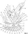
- Fig. 1
- eine perspektivische Ansicht einer Biegevorrichtung gemäss einer besonders bevorzugten Ausführungsform in einer Ausgangslage;
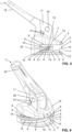
- Fig. 2
- eine Seitenansicht der
Figur 1 ; - Fig. 3
- eine Seitenansicht der Biegevorrichtung nach den vorhergehenden Figuren in einer ersten Biegelage;
- Fig. 4
- eine perspektivische Ansicht der
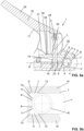
Figur 3 ; - Fig. 5a
- eine Schnittdarstellung der
Figuren 3 und 4 mit eingelegtem Rohr; - Fig. 5b
- eine Detailansicht der
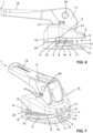
Figur 5a ; - Fig. 6
- eine Seitenansicht der Biegevorrichtung nach den vorhergehenden Figuren in einer zweiten Biegelage;
- Fig. 7
- eine perspektivische Ansicht der
Figur 6 ; - Fig. 8a
- eine Schnittdarstellung der
Figuren 6 und 7 mit eingelegtem Rohr; und - Fig. 8b
- eine Detailansicht der
Figur 8a . - In den Figuren wird eine Biegevorrichtung 1 gemäss einer Ausführungsform der vorliegenden Erfindung gezeigt. Ebenfalls wird in den Figuren eine Betätigungsanordnung 17 gezeigt. Die Biegevorrichtung 1 kann mit der Betätigungsanordnung 17 ausgebildet sein. Sowohl die Betätigungsanordnung 17 als auch die Biegevorrichtung 1 können unabhängig voneinander ausgebildet sein. Die Betätigungsanordnung 17 kann bei anderen, hier nicht gezeigten Vorrichtungen eingesetzt werden, und die Biegevorrichtung 1 kann mit anderen, hier nicht gezeigten Betätigungsanordnungen betätigt werden.
- Die Biegevorrichtung 1 dient zur Biegung von einem Rohr R mit einem Isolationsmantel I. Das Rohr R ist typischerweise aus Metall oder aus Verbundwerkstoff mit Metall und Kunststoff. Der Isolationsmantel I ist aus Schaumstoff. Der Isolationsmantel I umgibt das Rohr R aussenseitig und erstreckt sich typischerweise über dessen gesamten Länge.
- Biegevorrichtung 1 umfasst eine Biegematrizenanordnung 2 mit mindestens einer Biegematrize 3. In der gezeigten Ausführungsform umfasst die Biegematrize 3 zwei Matrizenteile, nämlich ein erstes Matrizenteil 14 und ein zweites Matrizenteil 15. Es ist aber auch denkbar, dass die Biegematrize nur aus einem Matrizenteil besteht.
- Die Biegematrize 3 stellt einen mit Seitenwänden 4, 5 teilweise begrenzten Aufnahmeraum 6 bereit. Der Aufnahmeraum 6 weist eine Zugangsöffnung 7 auf, über welche das Rohr R mit dem Isolationsmantel I in den Aufnahmeraum 6 für den Biegevorgang einlegbar ist.
- Weiter ist im Aufnahmeraum 6 mindestens eine Biegefläche 8 angeordnet, welche sich um eine Mittelachse M teilweise herum erstreckt. Beim Biegevorgang wird das Rohr R mit dem Isolationsmantel I um die Biegefläche 8 herum gebogen. In der gezeigten Ausführungsform erstreckt sich die Biegefläche um einen Winkel von mindestens 90°, insbesondere von mindestens 100°, um die Mittelachse M herum. Der Winkel ist im Wesentlichen vom gewünschten Rohr-Biegewinkel abhängig. Je nach Materialisierung des Rohrs muss der Winkel etwas grösser sein als der Rohr-Biegewinkel, weil das Rohr nach erfolgtem Biegevorgang zurückfedern kann.
- Weiter umfasst die Biegematrize 8 mindestens eine Verdrängungsausnehmung 9. Die mindestens eine Verdrängungsausnehmung 9 ist derart angeordnet, dass diese den Aufnahmeraum 6 vergrössert, so dass der Isolationsmantel I beim Biegevorgang in die Verdrängungsausnehmung 9 verdrängbar ist.
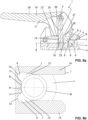
- In den
Figuren 5a, 5b und8a, 8b wird die Verdrängung des Isolationsmantels I entsprechend dargestellt. Das Rohr R in denFiguren 5a, 5b weist einen grösseren Durchmesser auf als das Rohr R in denFiguren 8a, 8b . Im eingelegten Zustand wird der Isolationsmantel I in die mindestens eine Verdrängungsausnehmung 9 verdrängt. Das heisst, der Isolationsmantel I fliesst gewissermassen in die mindestens eine Verdrängungsausnehmung 9 hinein. Das Rohr R liegt indirekt über den Isolationsmantel I an der Biegefläche 8 an, wobei an dieser Stelle der Isolationsmantel I komprimiert ist. Weiter erstreckt sich der Isolationsmantel I nicht nur in die mindestens eine Verdrängungsausnehmung 9 hinein, sondern er wird auch über die Zugangsöffnung 7 nach aussen hin verdrängt. - Von den Figuren wird ersichtlich, dass sich die mindestens eine Verdrängungsausnehmung 9 entlang der mindestens einen Biegefläche 8 erstreckt. Das heisst, die mindestens eine Verdrängungsausnehmung 9 liegt benachbart neben der Biegefläche 8. In der gezeigten Ausführungsform geht die Verdrängungsausnehmung 9 über eine konvexe Rundung 10 zur Biegefläche 8 über. In der gezeigten Ausführungsform sind zwei Biegeflächen 8 und zwei Verdrängungsausnehmungen 9 angeordnet. Die beiden Biegeflächen 8 liegen dabei zwischen den beiden Verdrängungsausnehmungen 9.
- Der Aufnahmeraum 6 weist von der Zugangsöffnung 7 her gesehen eine obere Seitenwand 4, eine beabstandet zur oberen Seitenwand 4 liegende untere Seitenwand 5, und eine den Aufnahmeraum 6 nach hinten hin abschliessende und gegenüber der Zugangsöffnung 7 liegende Rückwand 11 auf. Die beiden Seitenwände 4, 5 erstrecken sich von der Zugangsöffnung 7 zur Rückwand 11 hin. In der gezeigten Ausführungsform erstrecken sich die Verdrängungsausnehmungen 9 vom Aufnahmeraum 6 her gesehen in die jeweilige Seitenwand 4, 5 und in die Rückwand 11 hinein. Mit anderen Worten gesagt liegen die Verdrängungsausnehmungen 9 im Bereich des Übergangs von der Seitenwand 4, 5 zur Rückwand 11. An der Rückwand 11 liegt weiter die Biegefläche 11 bzw. je nach Ausbildung der Biegefläche 11 wird die Biegefläche 11 durch die Rückwand bereitgestellt.
- Die Verdrängungsausnehmung 9 erstreckt sich hier im Querschnitt entlang der Mittelachse in einem ersten Abschnitt 12 als konisch verlaufendes Flächensegment und in einem zweiten Abschnitt 13 als gerundetes Flächensegment erstreckt. Das konisch verlaufende Flächensegment liegt dabei so, dass die lichte Weite zwischen den beiden Verdrängungsausnehmungen 9 mit zunehmender Tiefe von der Zugangsöffnung 7 in den Aufnahmeraum 6 grösser wird. Das gerundete Flächensegment ist als konkave Rundung ausgebildet. Das gerundete Flächensegment geht mit der konvexen Rundung 10 zur Biegefläche 8 über.
- Der Aufnahmeraum 6 weist von der Zugangsöffnung 7 her gesehen einen Querschnitt auf, welcher bis zu Beginn des ersten Abschnitts konstant ist und sich dann aufgrund der Verdrängungsausnehmung 9 aufweitet. Durch den konstanten Querschnitt kann das Rohr R mit dem Isolationsmantel I während des Biegevorgangs gut entlang der Biegefläche 8 geführt werden. Hierbei gleitet das Rohr R mit zunehmendem Grad der Biegung weiter in den Aufnahmeraum 6 ein.
- Vorzugsweise ist der Querschnitt der Verdrängungsausnehmung 9 über deren gesamte Länge um die Mittelachse M im Wesentlichen konstant. Am Beginn und am Ende der Verdrängungsausnehmung 9 verläuft die Verdrängungsausnehmung 9 vorzugsweise so, dass deren Querschnitt mit geringer werdenden Distanz zum Beginn bzw. zum Ende kontinuierlich kleiner.
- Wie oben bereits erwähnt, ist die Biegematrize 3 zweiteilig mit einem ersten Matrizenteil 14 und einem zweiten Matrizenteil 15 ausgebildet. Die beiden Matrizenteile 14, 15 lassen sich von einer Ausgangslage in eine Biegelage aufeinander zu bewegen und dann wieder von der Biegelage in die Ausgangslage voneinander weg bewegen. In den
Figuren 1 und2 wird die Ausgangslage gezeigt. In der Ausgangslage lässt sich das Rohr R mit dem Isolationsmantel I über die Zugangsöffnung 7 in den Aufnahmeraum 6 einlegen. Anschliessend werden die beiden Matrizenteile in die Biegelage bewegt und das Rohr R kann gebogen werden. Während dem Biegevorgang wird der Isolationsmantel I kontinuierlich in die Verdrängungsausnehmung 9 verdrängt. - Das erste Matrizenteil 14 liegt auf einer Seite einer imaginären Ebene E und das zweite Matrizenteil 15 liegt auf einer anderen Seite der imaginären Ebene E. Die imaginäre Ebene E erstreckt sich rechtwinklig zur Mittelachse M und mittig durch den Aufnahmeraum 6 hindurch. Wenn die beiden Matrizenteile 14, 15 «auf Block» gefahren sind, so wie in den
Figuren 6 bis 8b gezeigt, bildet die imaginäre Ebene E eine Trennebene zwischen den beiden Matrizenteilen 14, 15. - In der gezeigten Ausführungsform weist jedes Matrizenteil 14, 15 Biegefläche 8 und eine Verdrängungsausnehmung 9 auf.
- In der gezeigten Ausführungsform stehen die beiden Matrizenteile 14, 15 über eine Führungsstruktur 16 bewegbar zueinander miteinander in Verbindung. Die Führungsstruktur 16 weist hier mehrere Führungsstifte auf, über die die Matrizenteile 14, 15 in Verbindung stehen. Das obere Matrizenteil 14 ist bezüglich den Führungsstiften bewegbar, und das untere Matrizenteil 15 ist fest zu den Führungsstiften gelagert.
- Die beiden Matrizenteile 14, 15 sind über eine Betätigungsanordnung 17 mit einem Betätigungselement 18 von der Ausgangslage in die Biegelage aufeinander zu bewegbar. Weiter weist die Führungsstruktur 16 vorzugsweise ein Rückstellelement 19 auf, welches die beiden Matrizenteile 14, 15 voneinander weg drückt. Bei Wegfall der Betätigung mit dem Betätigungselement 18 werden die beiden Matrizenteile 14, 15 durch das Rückstellelement 19 wieder in die Ausgangslage. Wie erwähnt, liegen die Matrizenteile 14, 15 vor dem Einlegen des Rohrs R in den Aufnahmeraum 6 in der Ausgangslage, und die Matrizenteile 14, 15 werden vor dem Biegevorgang in die Biegelage aufeinander zu bewegt, derart, dass die Isolation I des eingelegten Rohrs R teilweise komprimiert wird und teilweise in die Verdrängungsausnehmung gedrückt wird, und dass das Rohr R durch die Matrizenteile 14, 15 gehalten wird.
- In der gezeigten Ausführungsform liegen die Matrizenteile 14, 15 in Abhängigkeit vom Rohrdurchmesser relativ zueinander. Beim grösseren Rohrdurchmesser nach den
Figuren 3 bis 5b liegen die Matrizenteile 14, 15 in der Biegelage beabstandet zueinander und beim kleineren Durchmesser sind die beiden Matrizenteile 14, 15 in der Biegelage über Kontaktflächen 20 miteinander in Kontakt. - Die Betätigungsanordnung 17 umfasst eine sich entlang einer Lagerstangenachse L erstreckende Lagerstange 21, die über einen Lagerabschnitt 22 mit dem ersten Matrizenteil 14 in Verbindung steht und sich durch eine Öffnung 23 am zweiten Matrizenteil 15 hindurch erstreckt, und eine Schwenkstange 24, die sich entlang einer Schwenkstangenachse S erstreckt und die gegenüber dem Lagerabschnitt 22 an der Lagerstange 21 anordnet ist.
- Die Schwenkstangenachse S verläuft rechtwinklig zur Lagerstangenachse L. Das Betätigungselement 18 steht schwenkbar mit der Schwenkstange 24 in Verbindung. Hierfür weist das Betätigungselement 18 eine Öffnung 32 auf, in welche die Schwenkstange 24 einragt.
- Das Betätigungselement 18 weist eine Kontaktfläche 25 auf. Mit der Kontaktfläche 15 wirkt das Betätigungselement 18 auf eine Aktuatorfläche 26 am zweiten Matrizenteil 15. Die Kontaktfläche 25 weist mindestens zwei Flächensegmente 27, 28 auf, deren Abstand zur Schwenkstangenachse S unterschiedlich ist, derart, dass wenn das eine Flächensegment 27 mit der Aktuatorfläche 26 in Kontakt ist, der Abstand zwischen den Matrizenteilen 14, 15 unterschiedlich ist, als wenn ein anderes der Flächensegmente 28 mit der Aktuatorfläche 26 in Kontakt ist. Dies ist von den
Figuren 5a und8a gut ersichtlich. - Das Betätigungselement 18 weist einen Hebelabschnitt 29 auf. Der Hebelabschnitt 29 kann von einem Benutzer ergriffen werden und um die Schwenkachse S verschwenkt werden.
- Die Flächensegmente 27, 28 sind in den gezeigten Ausführungsformen als ebene Flächensegmente ausgebildet. Eine Ausbildung als gerundete Flächensegmente ist auch denkbar.
- Vorzugsweise ist zwischen den Flächensegmenten 27, 28 eine Übergangsfläche 30 angeordnet, wobei die Übergangsfläche 30 mit einer Rundung gerundet ausgebildet ist, wobei die Rundung derart ausgebildet ist, dass der Abstand zwischen der Rundung und der Schwenkstangenachse S sich zwischen den beiden Flächensegmenten 27, 28 vorzugsweise kontinuierlich verändert.
- Vorzugsweise weist das Betätigungselement 18 mindestens eine Markierung 31 auf, welche bei entsprechender Stellung des Betätigungselements 18 den Abstand zwischen den beiden Matrizenteilen 14, 15 vorgibt.
BEZUGSZEICHENLISTE 1 Biegevorrichtung 28 Flächensegment 2 Biegematrizenanordnung 29 Hebelabschnitt 3 Biegematrize 30 Übergangsfläche 4 Seitenwand 31 Markierung 5 Seitenwand 32 Öffnung 6 Aufnahmeraum 7 Zugangsöffnung M Mittelachse 8 Biegefläche R Rohr 9 Verdrängungsausnehmung I Isolationsmantel 10 konvexe Rundung 11 Rückwand E Ebene 12 erster Abschnitt 13 zweiter Abschnitt L Lagerstangenachse 14 erstes Matrizenteil S Schwenkstangenachse 15 zweites Matrizenteil 16 Führungsstruktur 17 Betätigungsanordnung 18 Betätigungselement 19 Rückstellelement 20 Kontaktfläche 21 Lagerstange 22 Lagerabschnitt 23 Öffnung 24 Schwenkstange 25 Kontaktfläche 26 Aktuatorfläche 27 Flächensegment
Claims (15)
- Biegevorrichtung (1) zur Biegung von einem Rohr (R) mit einem Isolationsmantel (I), umfassend eine Biegematrizenanordnung (2) mit mindestens einer Biegematrize (3),wobei die mindestens eine Biegematrize (3) einen mit Seitenwänden (4, 5) teilweise begrenzten Aufnahmeraum (6) bereitstellt, welcher Aufnahmeraum (6) eine Zugangsöffnung (7) aufweist, über welche das Rohr (R) mit dem Isolationsmantel (I) in den Aufnahmeraum (6) für den Biegevorgang einlegbar ist,wobei mindestens eine Biegefläche (8) im Aufnahmeraum (6) angeordnet ist, welche sich um eine Mittelachse (M) teilweise herum erstreckt, undwobei mindestens eine Verdrängungsausnehmung (9) derart angeordnet ist, dass diese den Aufnahmeraum (6) vergrössert, so dass der Isolationsmantel (I) beim Biegevorgang in die Verdrängungsausnehmung (9) verdrängbar ist.
- Biegevorrichtung (1) nach Anspruch 1, dadurch gekennzeichnet, dass sich die Verdrängungsausnehmung (9) entlang der Biegefläche (8) erstreckt, und/oder dass sich die Biegefläche (8) der Verdrängungsausnehmung (9) über eine konvexe Rundung (10) anschliesst.
- Biegevorrichtung (1) nach Anspruch 1 oder 2, dadurch gekennzeichnet, dass zwei oder mehr Biegeflächen (8) parallel zueinander angeordnet sind; und/oder dass zwei oder mehr Verdrängungsausnehmungen (9) angeordnet sind; und/oder dass pro Biegefläche (8) eine Verdrängungsausnehmung (9) angeordnet ist.
- Biegevorrichtung (1) nach einem der vorhergehenden Ansprüche, dadurch gekennzeichnet, dass quer zur Mittelachse (M) gesehen mindestens eine Biegefläche (8) zwischen zwei beabstandet zueinander liegenden Verdrängungsausnehmungen (9) angeordnet ist.
- Biegevorrichtung (1) nach einem der vorhergehenden Ansprüche, dadurch gekennzeichnet, dass der Aufnahmeraum (6) von der Zugangsöffnung her gesehen eine obere Seitenwand (4), eine beabstandet zur oberen Seitenwand (4) liegende untere Seitenwand (5), und den Aufnahmeraum (6) nach hinten hin abschliessende und gegenüber der Zugangsöffnung (7) liegende Rückwand (11) aufweist, wobei sich die Verdrängungsausnehmung (9) vom Aufnahmeraum (6) her gesehen in die obere Seitenwand (4) und/oder die untere Seitenwand (5) und/oder die Rückwand (11) hinein erstreckt.
- Biegevorrichtung (1) nach Anspruch 5, dadurch gekennzeichnet, dass sich die Verdrängungsausnehmung (9) im Querschnitt entlang der Mittelachse in einem ersten Abschnitt (12) als konisch verlaufendes Flächensegment und in einem zweiten Abschnitt (13) als gerundetes Flächensegment erstreckt.
- Biegevorrichtung (1) nach einem der vorhergehenden Ansprüche, dadurch gekennzeichnet, dass die Biegematrize (3) zweiteilig mit einem ersten Matrizenteil (14) und einem zweiten Matrizenteil (15) ausgebildet ist.
- Biegevorrichtung (1) nach Anspruch 7, dadurch gekennzeichnet, dass das erste Matrizenteil (14) auf einer Seite einer imaginären Ebene (E) liegt und dass das zweite Matrizenteil (15) auf einer anderen Seite der imaginären Ebene (E) liegt, wobei die imaginäre Ebene (E) sich rechtwinklig zur Mittelachse (M) und mittig durch den Aufnahmeraum (6) hindurch erstreckt.
- Biegevorrichtung (1) nach Anspruch 7 oder 8, dadurch gekennzeichnet,dass jedes Matrizenteil (14, 15) die mindestens eine Biegefläche (8) aufweist; wobei entweder jedes Matrizenteil (14, 15) die mindestens eine Verdrängungsausnehmung (9) aufweist, oder wobei nur eines der beiden Matrizenteile (14, 15) die mindestens eine Verdrängungsausnehmung (9) aufweist; oderdass nur eines der beiden Matrizenteile (14, 15) die mindestens eine Verdrängungsausnehmung (9) aufweist; wobei entweder jedes Matrizenteil (14, 15) die mindestens eine Biegefläche (8) aufweist, oder wobei nur eines der beiden Matrizenteile die mindestens eine Biegefläche (8) aufweist.
- Biegevorrichtung (1) nach einem der Ansprüche 7 bis 9, dadurch gekennzeichnet, dass die beiden Matrizenteile (14, 15) über eine Führungsstruktur (16) bewegbar zueinander miteinander in Verbindung stehen, wobei die beiden Matrizenteile (14, 15) über eine Betätigungsanordnung (17) mit einem Betätigungselement (18) aufeinander zu bewegbar sind, und wobei die Führungsstruktur (16) vorzugsweise ein Rückstellelement (19) aufweist, welches die beiden Matrizenteile (14, 15) voneinander weg drückt.
- Biegevorrichtung (1) nach einem der vorhergehenden Ansprüche 7 bis 10, dadurch gekennzeichnet, dass die Matrizenteile (14, 15) vor dem Einlegen des Rohrs (R) in den Aufnahmeraum (6) in einer Ausgangslage liegen und dass die Matrizenteile (14, 15) vor dem Biegevorgang in eine Biegelage aufeinander zu bewegt werden, derart, dass die Isolation (I) des eingelegten Rohrs (R) teilweise komprimiert wird und teilweise in die Verdrängungsausnehmung gedrückt wird, und dass das Rohr (R) durch die Matrizenteile (14, 15) geklemmt wird.
- Biegevorrichtung (1) nach Anspruch 11, dadurch gekennzeichnet, dass die Matrizenteile (14, 15) in der Biegelage beabstandet zueinander liegen oder über Kontaktflächen (20) miteinander in Kontakt bringbar sind.
- Biegevorrichtung (1) nach einem der Ansprüche 10 bis 12 oder Betätigungsanordnung (17) mit einem Betätigungselement (18) zur Bereitstellung einer Bewegung zwischen einem ersten Matrizenteil (14) und einem zweiten Matrizenteil (15),wobei die Betätigungsanordnung (17)eine sich entlang einer Lagerstangenachse (L) erstreckende Lagerstange (21), die über einen Lagerabschnitt (22) mit dem ersten Matrizenteil (14) in Verbindung steht und sich durch eine Öffnung (23) am zweiten Matrizenteil (15) hindurch erstreckt, undeine Schwenkstange (24), die sich entlang einer Schwenkstangenachse (S) erstreckt und die gegenüber dem Lagerabschnitt (22) an der Lagerstange (21) anordnet ist, umfasst,wobei die Schwenkstangenachse (S) rechtwinklig zur Lagerstangenachse (L) verläuft,dass das Betätigungselement (18) schwenkbar mit der Schwenkstange (24) in Verbindung steht,wobei das Betätigungselement (18) eine Kontaktfläche (25) aufweist, mit welcher das Betätigungselement (18) auf eine Aktuatorfläche (26) am zweiten Matrizenteil (15) wirkt, wobei die Kontaktfläche (25) mindestens zwei Flächensegmente (27, 28) aufweist, deren Abstand zur Schwenkstangenachse (S) unterschiedlich ist, derart, dass wenn das eine Flächensegment (27) mit der Aktuatorfläche (26) in Kontakt ist, der Abstand zwischen den Matrizenteilen (14, 15) unterschiedlich ist, als wenn ein anderes der Flächensegmente (28) mit der Aktuatorfläche (26) in Kontakt ist.
- Biegevorrichtung (1) oder Betätigungsanordnung (17) nach Anspruch 13, dadurch gekennzeichnet,dass das Betätigungselement (18) einen Hebelabschnitt (29) aufweist und/oderdass die Flächensegmente (27, 28) als ebene oder als gerundete Flächensegmente ausgebildet sind; und/oderdass zwischen den Flächensegmenten (27, 28) eine Übergangsfläche (30) angeordnet ist, wobei die Übergangsfläche (30) mit einer Rundung gerundet ausgebildet ist, wobei die Rundung derart ausgebildet ist, dass der Abstand zwischen der Rundung und der Schwenkstangenachse (S) sich zwischen den beiden Flächensegmenten (27, 28) vorzugsweise kontinuierlich verändert.
- Biegevorrichtung (1) oder Betätigungsanordnung (17) nach Anspruch 13 oder 14, dadurch gekennzeichnet, dass das Betätigungselement (18) mindestens eine Markierung (31) aufweist, welche bei entsprechender Stellung des Betätigungselements (18) den Abstand zwischen den beiden Matrizenteilen (14, 15) vorgibt.
Priority Applications (1)
| Application Number | Priority Date | Filing Date | Title |
|---|---|---|---|
| EP23162871.0A EP4434650A1 (de) | 2023-03-20 | 2023-03-20 | Biegevorrichtung |
Applications Claiming Priority (1)
| Application Number | Priority Date | Filing Date | Title |
|---|---|---|---|
| EP23162871.0A EP4434650A1 (de) | 2023-03-20 | 2023-03-20 | Biegevorrichtung |
Publications (1)
| Publication Number | Publication Date |
|---|---|
| EP4434650A1 true EP4434650A1 (de) | 2024-09-25 |
Family
ID=85704601
Family Applications (1)
| Application Number | Title | Priority Date | Filing Date |
|---|---|---|---|
| EP23162871.0A Pending EP4434650A1 (de) | 2023-03-20 | 2023-03-20 | Biegevorrichtung |
Country Status (1)
| Country | Link |
|---|---|
| EP (1) | EP4434650A1 (de) |
Citations (13)
| Publication number | Priority date | Publication date | Assignee | Title |
|---|---|---|---|---|
| US3023650A (en) * | 1960-02-01 | 1962-03-06 | Marie C Sterner | Hand-operated tube-bending machine |
| US4132100A (en) * | 1976-04-07 | 1979-01-02 | Schuler Jacob P | Hand-operated tool for bending pipes |
| GB2226268A (en) * | 1988-12-13 | 1990-06-27 | Lee Chin Piao | A paper-perforator |
| US5142895A (en) * | 1989-05-15 | 1992-09-01 | Amana Refrigeration, Inc. | Method for bending tubes |
| US5337590A (en) * | 1993-12-27 | 1994-08-16 | Schuchert Eugene H | Method and apparatus for bending tubes using split bend die |
| EP0878250A2 (de) * | 1997-05-13 | 1998-11-18 | Megatronic Schweissmaschinenbau GmbH | Biegestelle eines dornlos gebogenen dünnwendigen Metallrohres und Vorrichtung zur Herstellung einer solchen Biegestelle |
| CN2467222Y (zh) * | 2001-02-18 | 2001-12-26 | 王福华 | 多功位铝合金手动冲压机 |
| US20080110223A1 (en) * | 2006-11-15 | 2008-05-15 | Benteler Automobiltechnik Gmbh | Bending device for a tubular member |
| DE102008031276A1 (de) * | 2008-07-02 | 2010-01-07 | Benteler Automobiltechnik Gmbh | Biegewerkzeug und Faltenglätter für ein Biegewerkzeug |
| US20110314982A1 (en) * | 2009-03-06 | 2011-12-29 | Nitta Corporation | Sheet cutter and belt processing tool |
| US8375764B2 (en) | 2010-10-07 | 2013-02-19 | Chang Yang Huang | Pipe bender |
| CN110064684A (zh) * | 2018-01-24 | 2019-07-30 | 宁波兴业盛泰集团有限公司 | 一种金属带材折弯机及其折弯工艺 |
| WO2020100048A1 (en) * | 2018-11-16 | 2020-05-22 | Cml International S.P.A. | Machine for bending an elongated workpiece without wrinkling |
-
2023
- 2023-03-20 EP EP23162871.0A patent/EP4434650A1/de active Pending
Patent Citations (13)
| Publication number | Priority date | Publication date | Assignee | Title |
|---|---|---|---|---|
| US3023650A (en) * | 1960-02-01 | 1962-03-06 | Marie C Sterner | Hand-operated tube-bending machine |
| US4132100A (en) * | 1976-04-07 | 1979-01-02 | Schuler Jacob P | Hand-operated tool for bending pipes |
| GB2226268A (en) * | 1988-12-13 | 1990-06-27 | Lee Chin Piao | A paper-perforator |
| US5142895A (en) * | 1989-05-15 | 1992-09-01 | Amana Refrigeration, Inc. | Method for bending tubes |
| US5337590A (en) * | 1993-12-27 | 1994-08-16 | Schuchert Eugene H | Method and apparatus for bending tubes using split bend die |
| EP0878250A2 (de) * | 1997-05-13 | 1998-11-18 | Megatronic Schweissmaschinenbau GmbH | Biegestelle eines dornlos gebogenen dünnwendigen Metallrohres und Vorrichtung zur Herstellung einer solchen Biegestelle |
| CN2467222Y (zh) * | 2001-02-18 | 2001-12-26 | 王福华 | 多功位铝合金手动冲压机 |
| US20080110223A1 (en) * | 2006-11-15 | 2008-05-15 | Benteler Automobiltechnik Gmbh | Bending device for a tubular member |
| DE102008031276A1 (de) * | 2008-07-02 | 2010-01-07 | Benteler Automobiltechnik Gmbh | Biegewerkzeug und Faltenglätter für ein Biegewerkzeug |
| US20110314982A1 (en) * | 2009-03-06 | 2011-12-29 | Nitta Corporation | Sheet cutter and belt processing tool |
| US8375764B2 (en) | 2010-10-07 | 2013-02-19 | Chang Yang Huang | Pipe bender |
| CN110064684A (zh) * | 2018-01-24 | 2019-07-30 | 宁波兴业盛泰集团有限公司 | 一种金属带材折弯机及其折弯工艺 |
| WO2020100048A1 (en) * | 2018-11-16 | 2020-05-22 | Cml International S.P.A. | Machine for bending an elongated workpiece without wrinkling |
Similar Documents
| Publication | Publication Date | Title |
|---|---|---|
| DE69705851T2 (de) | Vorrichtung zum richten von draht | |
| DE69215724T2 (de) | Wendeschneidplatte | |
| EP3718184A2 (de) | Klemmbacken und schneiden für eine abisolierzange, sowie abisolierzange | |
| DE2715178A1 (de) | Handwerkzeug zum biegen von rohren | |
| WO2019105707A1 (de) | Abisolierzange | |
| EP3718186A1 (de) | Abisolierzange | |
| EP3587173A1 (de) | Verstellbarer höhenbegrenzer | |
| DE19817849B4 (de) | Kipphebel | |
| DE68911386T2 (de) | Verriegelungsfeder für Verbinder. | |
| DE2708841C2 (de) | Anschlußklemme für isolierte elektrische Leiter | |
| DE1900741C3 (de) | Vorrichtung zur Formgebung konischer Metallrohre | |
| EP3098357B1 (de) | Betätigungsvorrichtung für ein ablaufventil eines spülkastens | |
| DE4231564C2 (de) | Buchsenkontakt mit einem Anker | |
| DE102006052309A1 (de) | Tellerfeder-Vorrichtung, Führungsachse und Tellerfeder hierfür | |
| EP1183114B1 (de) | Biegedorn für eine biegevorrichtung und biegeverfahren für rohre | |
| EP0675564B1 (de) | Schrägstehender Schneid-Klemm-Kontakt | |
| DE3508939A1 (de) | Elektrische klemme | |
| DE2006109A1 (de) | Vorrichtung zum Biegen von Metallrohren | |
| DE69003021T2 (de) | Isolierender Abstandshalter. | |
| DE3300769A1 (de) | Aehrenheber fuer fingerbalkenmaehwerke von erntemaschinen | |
| DE69820398T2 (de) | Verfahren zum Stanzen von Schubladenführungen | |
| EP3918699B1 (de) | Vorrichtung zum biegen mindestens eines in einem ausgangszustand u-förmigen leiterstücks und ein entsprechendes verfahren | |
| DE19640119C2 (de) | Biegewerkzeug | |
| DE8702746U1 (de) | Vorrichtung zum Entfernen von Isolierung | |
| DE2058464A1 (de) | Loesbares Spann- und Halteglied fuer Seile |
Legal Events
| Date | Code | Title | Description |
|---|---|---|---|
| PUAI | Public reference made under article 153(3) epc to a published international application that has entered the european phase |
Free format text: ORIGINAL CODE: 0009012 |
|
| STAA | Information on the status of an ep patent application or granted ep patent |
Free format text: STATUS: THE APPLICATION HAS BEEN PUBLISHED |
|
| AK | Designated contracting states |
Kind code of ref document: A1 Designated state(s): AL AT BE BG CH CY CZ DE DK EE ES FI FR GB GR HR HU IE IS IT LI LT LU LV MC ME MK MT NL NO PL PT RO RS SE SI SK SM TR |
|
| STAA | Information on the status of an ep patent application or granted ep patent |
Free format text: STATUS: REQUEST FOR EXAMINATION WAS MADE |
|
| 17P | Request for examination filed |
Effective date: 20250122 |