EP4434412A1 - Vorrichtung zur herstellung von brauchwasser mit automatischer gasfüllung und funktionen zur erkennung verbleibender mengen und verwendungsverfahren dafür - Google Patents
Vorrichtung zur herstellung von brauchwasser mit automatischer gasfüllung und funktionen zur erkennung verbleibender mengen und verwendungsverfahren dafür Download PDFInfo
- Publication number
- EP4434412A1 EP4434412A1 EP22894409.6A EP22894409A EP4434412A1 EP 4434412 A1 EP4434412 A1 EP 4434412A1 EP 22894409 A EP22894409 A EP 22894409A EP 4434412 A1 EP4434412 A1 EP 4434412A1
- Authority
- EP
- European Patent Office
- Prior art keywords
- air inlet
- gas filling
- machine
- snap
- rod
- Prior art date
- Legal status (The legal status is an assumption and is not a legal conclusion. Google has not performed a legal analysis and makes no representation as to the accuracy of the status listed.)
- Pending
Links
Images


Classifications
-
- B—PERFORMING OPERATIONS; TRANSPORTING
- B67—OPENING, CLOSING OR CLEANING BOTTLES, JARS OR SIMILAR CONTAINERS; LIQUID HANDLING
- B67D—DISPENSING, DELIVERING OR TRANSFERRING LIQUIDS, NOT OTHERWISE PROVIDED FOR
- B67D1/00—Apparatus or devices for dispensing beverages on draught
- B67D1/0042—Details of specific parts of the dispensers
- B67D1/0057—Carbonators
- B67D1/0069—Details
- B67D1/0071—Carbonating by injecting CO2 in the liquid
-
- A—HUMAN NECESSITIES
- A47—FURNITURE; DOMESTIC ARTICLES OR APPLIANCES; COFFEE MILLS; SPICE MILLS; SUCTION CLEANERS IN GENERAL
- A47J—KITCHEN EQUIPMENT; COFFEE MILLS; SPICE MILLS; APPARATUS FOR MAKING BEVERAGES
- A47J31/00—Apparatus for making beverages
-
- A—HUMAN NECESSITIES
- A23—FOODS OR FOODSTUFFS; TREATMENT THEREOF, NOT COVERED BY OTHER CLASSES
- A23L—FOODS, FOODSTUFFS OR NON-ALCOHOLIC BEVERAGES, NOT OTHERWISE PROVIDED FOR; PREPARATION OR TREATMENT THEREOF
- A23L2/00—Non-alcoholic beverages; Dry compositions or concentrates therefor; Preparation or treatment thereof
- A23L2/52—Adding ingredients
- A23L2/54—Mixing with gases
-
- A—HUMAN NECESSITIES
- A47—FURNITURE; DOMESTIC ARTICLES OR APPLIANCES; COFFEE MILLS; SPICE MILLS; SUCTION CLEANERS IN GENERAL
- A47J—KITCHEN EQUIPMENT; COFFEE MILLS; SPICE MILLS; APPARATUS FOR MAKING BEVERAGES
- A47J31/00—Apparatus for making beverages
- A47J31/40—Beverage-making apparatus with dispensing means for adding a measured quantity of ingredients, e.g. coffee, water, sugar, cocoa, milk, tea
-
- B—PERFORMING OPERATIONS; TRANSPORTING
- B01—PHYSICAL OR CHEMICAL PROCESSES OR APPARATUS IN GENERAL
- B01F—MIXING, e.g. DISSOLVING, EMULSIFYING OR DISPERSING
- B01F23/00—Mixing according to the phases to be mixed, e.g. dispersing or emulsifying
- B01F23/20—Mixing gases with liquids
- B01F23/23—Mixing gases with liquids by introducing gases into liquid media, e.g. for producing aerated liquids
- B01F23/231—Mixing gases with liquids by introducing gases into liquid media, e.g. for producing aerated liquids by bubbling
-
- B—PERFORMING OPERATIONS; TRANSPORTING
- B01—PHYSICAL OR CHEMICAL PROCESSES OR APPARATUS IN GENERAL
- B01F—MIXING, e.g. DISSOLVING, EMULSIFYING OR DISPERSING
- B01F23/00—Mixing according to the phases to be mixed, e.g. dispersing or emulsifying
- B01F23/20—Mixing gases with liquids
- B01F23/23—Mixing gases with liquids by introducing gases into liquid media, e.g. for producing aerated liquids
- B01F23/236—Mixing gases with liquids by introducing gases into liquid media, e.g. for producing aerated liquids specially adapted for aerating or carbonating beverages
- B01F23/2361—Mixing gases with liquids by introducing gases into liquid media, e.g. for producing aerated liquids specially adapted for aerating or carbonating beverages within small containers, e.g. within bottles
-
- B—PERFORMING OPERATIONS; TRANSPORTING
- B01—PHYSICAL OR CHEMICAL PROCESSES OR APPARATUS IN GENERAL
- B01F—MIXING, e.g. DISSOLVING, EMULSIFYING OR DISPERSING
- B01F35/00—Accessories for mixers; Auxiliary operations or auxiliary devices; Parts or details of general application
- B01F35/20—Measuring; Control or regulation
- B01F35/21—Measuring
- B01F35/211—Measuring of the operational parameters
- B01F35/2117—Weight
-
- B—PERFORMING OPERATIONS; TRANSPORTING
- B67—OPENING, CLOSING OR CLEANING BOTTLES, JARS OR SIMILAR CONTAINERS; LIQUID HANDLING
- B67D—DISPENSING, DELIVERING OR TRANSFERRING LIQUIDS, NOT OTHERWISE PROVIDED FOR
- B67D1/00—Apparatus or devices for dispensing beverages on draught
- B67D1/0042—Details of specific parts of the dispensers
- B67D1/0057—Carbonators
- B67D1/0069—Details
- B67D1/0074—Automatic carbonation control
-
- B—PERFORMING OPERATIONS; TRANSPORTING
- B67—OPENING, CLOSING OR CLEANING BOTTLES, JARS OR SIMILAR CONTAINERS; LIQUID HANDLING
- B67D—DISPENSING, DELIVERING OR TRANSFERRING LIQUIDS, NOT OTHERWISE PROVIDED FOR
- B67D1/00—Apparatus or devices for dispensing beverages on draught
- B67D1/08—Details
- B67D1/12—Flow or pressure control devices or systems, e.g. valves, gas pressure control, level control in storage containers
- B67D1/1202—Flow control, e.g. for controlling total amount or mixture ratio of liquids to be dispensed
- B67D1/1204—Flow control, e.g. for controlling total amount or mixture ratio of liquids to be dispensed for ratio control purposes
- B67D1/1225—Weighing
-
- G—PHYSICS
- G01—MEASURING; TESTING
- G01G—WEIGHING
- G01G19/00—Weighing apparatus or methods adapted for special purposes not provided for in the preceding groups
- G01G19/62—Over or under weighing apparatus
-
- G—PHYSICS
- G01—MEASURING; TESTING
- G01L—MEASURING FORCE, STRESS, TORQUE, WORK, MECHANICAL POWER, MECHANICAL EFFICIENCY, OR FLUID PRESSURE
- G01L19/00—Details of, or accessories for, apparatus for measuring steady or quasi-steady pressure of a fluent medium insofar as such details or accessories are not special to particular types of pressure gauges
- G01L19/08—Means for indicating or recording, e.g. for remote indication
- G01L19/12—Alarms or signals
-
- G—PHYSICS
- G01—MEASURING; TESTING
- G01M—TESTING STATIC OR DYNAMIC BALANCE OF MACHINES OR STRUCTURES; TESTING OF STRUCTURES OR APPARATUS, NOT OTHERWISE PROVIDED FOR
- G01M3/00—Investigating fluid-tightness of structures
- G01M3/02—Investigating fluid-tightness of structures by using fluid or vacuum
- G01M3/26—Investigating fluid-tightness of structures by using fluid or vacuum by measuring rate of loss or gain of fluid, e.g. by pressure-responsive devices, by flow detectors
Definitions
- the invention relates to the field of preparation of soda water drinks, in particular to a soda machine with automatic gas filling and residual amount detection functions and a method for using the same.
- An existing soda machine is not high in safety and can perform automatic gas filling in various states, making it relatively dangerous. If the machine is touched by mistake, a large amount of carbon dioxide gas will overflow into the air, which easily causes the excessively high indoor carbon dioxide concentration, or direct spraying of the high-concentration carbon dioxide gas to the people.
- pressure detection is generally adopted for detection of the residual amount of the carbon dioxide gas; however, relatively large gas pressure fluctuations will only be generated during pressure detection when the residual amount of the carbon dioxide gas in a carbon dioxide gas cylinder is very small, such that it is difficult for a user to timely determine whether it is needed to start to prepare a new carbon dioxide gas cylinder.
- the invention aims to provide a soda machine which is safer and capable of detecting the residual amount of carbon dioxide.
- a soda machine with automatic gas filling and residual amount detection functions comprises:
- a pin is provided on the driving end, a strip-shaped groove is provided at the driving end, and the pin is inserted in the strip-shaped groove and moves in the strip-shaped groove.
- an air inlet gland is provided on the air inlet body, two opposite pivoting shaft holes are provided in an upper surface of the air inlet gland, a through hole for accommodating the air inlet rod is provided in the middle of the air inlet gland, two pivoting columns respectively movably inserted in the two pivoting shaft holes are provided at the tail end of the air inlet pressing rod, and the air inlet rod is located at a lower end of the middle of the air inlet pressing rod.
- a first reset spring abutting against the bottom of the air inlet pressing rod is provided on a surface of the air inlet gland, and a second reset spring for driving the gas filling snap-fitting rod to be reset is provided on the electric control driver.
- two supporting feet provided symmetrically and expanding downwards are located at a front end of the air inlet pressing rod, end portions of the two supporting feet are connected by means of a connection rod, a cylinder platform is provided at the bottom of one of the supporting feet, the snap-fitting hole is provided in a side surface of the cylinder platform, and the air inlet button is located above the connection rod.
- the machine head detection switch, the inductive switch and the water bottle detection switch are all inching switches.
- the reminding device is a display screen provided on a surface of the main machine or the machine head.
- a method for using the soda machine comprises a mounting method, a determination method and carbon dioxide residual amount calculation, wherein
- the longest gas filling time is 12 seconds.
- the invention has the beneficial effects as follows: the soda machine is safer to operate, cannot carry out automatic gas filling under the condition that the operation of the soda machine is not standard and can only carry out manual gas filling by a user under a special condition, so that the safety is higher; and meanwhile, the amount of residual carbon dioxide gas can be measured in real time according to the weight of the carbon dioxide gas cylinder, so that the user can conveniently prepare the standby carbon dioxide gas cylinder in time, and more convenience is achieved.
- orientation statements such as orientation or position relationships indicated by up, down, front, back, left, right, etc., are based on the orientation or position relationships shown in the accompanying drawings and are only to facilitate the statement of the invention and simplify the statement, rather than indicate or imply that the device or element referred to must have a specific orientation, be constructed and operate in a specific orientation, and therefore should not be understood as a limitation to the invention.
- “several” means one or more, "a plurality of” means two or more, “greater than”, “less than”, and “more than”, etc. are understood to exclude the original number, and above, below, within, etc. are understood to include the original number. If there is a statement of first and second, it is only for the purpose of distinguishing technical features, and cannot be understood as indicating or implying the relative importance or implicitly indicating the number of indicated technical features or implicitly indicating the order of indicated technical features.
- a soda machine with automatic gas filling and residual amount detection functions includes:
- the solution further discloses a method for using the product, the method including a mounting method, a determination method and carbon dioxide residual amount calculation, wherein
- the soda machine is safer to operate, the automatic gas filling mode cannot be enabled under the condition that the operation of the soda machine is not standard and, only the manual gas refilling mode can be enabled, while the manual gas filling mode needs to be performed by a user under a special condition, thus, at this time, the user's attention will be focused on the use of the carbonated water maker, dangers do not occur easily, so that the safety is higher; and meanwhile, the amount of residual carbon dioxide gas can be measured in real time according to the weight of the carbon dioxide gas cylinder 14, so that the user can conveniently prepare the standby carbon dioxide gas cylinder 14 in time, and more convenience is achieved.
- the large and small gas cylinders can be automatically recognized by the soda machine according to the measured weight, for example, the empty bottle weight of the carbon dioxide gas cylinder 14 in 0.6 L is 780 g, the gas weight is 380 g, and the total weight is 1160 g; the empty bottle weight of the carbon dioxide gas cylinder 14 in 1.34 L is 1635 g, the gas weight is 880 g, and the total weight is 2515 g; when the total weight exceeds the empty bottle weight of the carbon dioxide gas cylinder 14 in 1.34 L, the gas cylinder is determined as the large gas cylinder by a system, and vice versa as the small gas cylinder; and after the large and small gas cylinders are recognized, the dead weight of the carbon dioxide gas cylinder 14 and the weight of the air inlet body are subtracted by the measured weight, for example, the empty bottle weight of the carbon dioxide gas cylinder 14 in 0.6 L is 780 g, the gas weight is 380 g, and the total weight is 1160 g; the empty bottle weight of the carbon dioxide gas cylinder
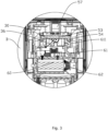
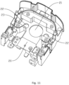
- a connection hole 21 for accommodating the gas cylinder joint is provided in the middle of the body bracket 20, limiting holes 22 located on two sides of the connection hole 21 are provided in the body bracket 20, platens 32 located in the limiting holes 22 are provided at a lower end of the air inlet body 30, there are two weight sensors 44 which are located below the two limiting holes 22, respectively, an upward embedding groove 23 is provided at a lower end of the body bracket 20, the top of the embedding groove 23 is in communication with an upper end surface of the body bracket 20, the support member 40 is pivotally connected in the embedding groove 23 by means of a pivoting shaft, and the pushing end extends to the upper end of the body bracket 20 through the top of the embedding groove 23 and is located at the bottom of the air inlet body 30 so as to support the air inlet body 30; the displacement of the air inlet body 30 is limited by means of the connection hole 21 and the limiting holes 22, such that the air inlet body can only move up and down, and the air inlet body is vertically adjusted by
- weight sensors 44 there can also be three or more weight sensors 44, the weight sensors 44 can also be directly received at the bottom of the air inlet body 30, or wings are provided on two sides of the air inlet body 30, the weight sensors 44 are located at lower ends of the wings, and the specific number and arrangement layout of the weight sensors 44 can be changed organically according to actual needs.
- the support member 40 is in a sheet shape, and the pushing end is a pushing protrusion 41 provided on the support member 40.
- the pushing end can also be a pushing rod taking a pivot point of the support member 40 as the center and eccentrically provided on an end surface of the support member 40, such that the height of the pushing rod can be driven to change in the swinging process of the support member 40.
- an abutting surface 33 and an avoiding position 34 located on one side of the abutting surface 33 and recessed inwards are provided at the bottom of the air inlet body 30, and the avoiding position 34 is in smooth transition with the abutting surface 33, such that the pushing end can abut against the abutting surface 33 in the swinging process so as to support the air inlet body 30 or can move into the avoiding position 34 along the abutting surface 33.
- the driving end 111 can be connected to the driven end 42 in various manners, preferably, a pin 112 is provided at the driving end 111, a strip-shaped groove 43 is provided in the driving end 42, and the pin 112 is inserted in the strip-shaped groove 43 and moves in the strip-shaped groove 43.
- the pin 112 can move in the strip-shaped groove 43, thereby driving the driven end 42 to swing.
- the movable connection style of the driving end 111 and the driven end 42 is shown as pivotally connecting a telescopic rod to the driving end 111, the other end of the telescopic rod is pivotally connected to the driven end 42, thereby forming a crank connection rod 53 structure for driving.
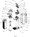
- an air inlet gland 35 is provided on the air inlet body 30, two opposite pivoting shaft holes 351 are provided in an upper surface of the air inlet gland 35, a through hole for accommodating the air inlet rod 31 is provided in the middle of the air inlet gland 35, two pivoting columns 51 respectively movably inserted in the two pivoting shaft holes 351 are provided at the tail end of the air inlet pressing rod 50, and the air inlet rod 31 is located at a lower end of the middle of the air inlet pressing rod 50.
- an end portion of the air inlet pressing rod 50 can be directly and pivotally connected to an inner side wall of the main machine 10.
- the air inlet pressing rod 50 can rebound automatically under the rebounding action of an ejector pin on the carbon dioxide gas cylinder 14. Considering increasing the reset elasticity to prevent the air inlet pressing rod 50 from being pressed against the air inlet rod 31 for a long time, preferably, a first reset spring 56 abutting against the bottom of the air inlet pressing rod 50 is provided on a surface of the air inlet gland 35.
- the electric control driver 60 can be selected to be in the type of automatic reset upon a power outage. However, considering increasing the response speed, preferably, a second reset spring 62 for driving the gas filling snap-fitting rod 61 to be reset is provided on the electric control driver 60, such that in case of the power outage, the second reset spring 62 can quickly drive the gas filling snap-fitting rod 61 to be reset.
- the electric control driver 60 is preferably an electromagnetic valve, and the electric control driver 60 can also be selected as a linear motor and other implementations.
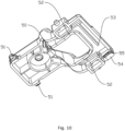
- two supporting feet 52 provided symmetrically and expanding downwards are located at a front end of the air inlet pressing rod 50, end portions of the two supporting feet 52 are connected by means of a connection rod 53, a cylinder platform 54 is provided at the bottom of one of the supporting feet 52, the snap-fitting hole 55 is provided in a side surface of the cylinder platform 54, the air inlet button 57 is located above the connection rod 53, preferably, the air inlet button 57 is sleeved with an air inlet button bracket, and the air inlet button bracket is pivotally connected to outer sides of the two supporting feet 52.
- the machine head detection switch, the inductive switch 58 and the water bottle detection switch are preferably inching switches.
- the machine head detection switch, the inductive switch 58 and the water bottle detection switch can also be selected as electricity connection rods and breakpoint circuits fitted with the electricity connection rods, and the circuits can only be turned on when the electricity connection rods are in contact with breakpoint circuits.
- the machine head detection switch, the inductive switch 58 and the water bottle detection switch can also be selected as touch switches and other implementations.
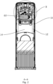
- the reminding device is a display screen 90 provided on a surface of the main machine 10 or the machine head 11, such that the carbon dioxide residual amount and fault causes are displayed more directly.
- the reminding device can be in the form of an indicator light or in the form of a voice speaker.
- a rotation stopping pressing rod 91 extending into the machine head 11 is further provided on the main machine 10, such that when the machine head 11 is reset to a specified state, the rotation stopping pressing rod 91 abuts against the interior of the machine head 11 so as to limit further swinging of the machine head 11.
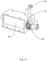
- a gas cylinder cavity 12 located below the air inlet body 30 is provided in the main machine 10, an opening is provided in one end of the gas cylinder cavity 12, and a rear cover 13 is movably provided on the opening, thereby accommodating the carbon dioxide gas cylinder 14 conveniently.
- a backup battery is provided in the main machine 10, such that in case of a power outage, the carbon dioxide gas cylinder 14 can also be weighed.
Landscapes
- Chemical & Material Sciences (AREA)
- Chemical Kinetics & Catalysis (AREA)
- Physics & Mathematics (AREA)
- General Physics & Mathematics (AREA)
- Engineering & Computer Science (AREA)
- Food Science & Technology (AREA)
- Health & Medical Sciences (AREA)
- Nutrition Science (AREA)
- Life Sciences & Earth Sciences (AREA)
- Polymers & Plastics (AREA)
- Filling Or Discharging Of Gas Storage Vessels (AREA)
- Accessories For Mixers (AREA)
Applications Claiming Priority (2)
| Application Number | Priority Date | Filing Date | Title |
|---|---|---|---|
| CN202111364763.0A CN113974433B (zh) | 2021-11-17 | 2021-11-17 | 一种具有自动加气和余量检测功能的气泡水机及其使用方法 |
| PCT/CN2022/118173 WO2023087870A1 (zh) | 2021-11-17 | 2022-09-09 | 一种具有自动加气和余量检测功能的气泡水机及其使用方法 |
Publications (2)
| Publication Number | Publication Date |
|---|---|
| EP4434412A1 true EP4434412A1 (de) | 2024-09-25 |
| EP4434412A4 EP4434412A4 (de) | 2025-11-26 |
Family
ID=79749159
Family Applications (1)
| Application Number | Title | Priority Date | Filing Date |
|---|---|---|---|
| EP22894409.6A Pending EP4434412A4 (de) | 2021-11-17 | 2022-09-09 | Vorrichtung zur herstellung von brauchwasser mit automatischer gasfüllung und funktionen zur erkennung verbleibender mengen und verwendungsverfahren dafür |
Country Status (5)
| Country | Link |
|---|---|
| US (1) | US12509341B2 (de) |
| EP (1) | EP4434412A4 (de) |
| JP (1) | JP2024540685A (de) |
| CN (1) | CN113974433B (de) |
| WO (1) | WO2023087870A1 (de) |
Families Citing this family (6)
| Publication number | Priority date | Publication date | Assignee | Title |
|---|---|---|---|---|
| CN113974433B (zh) | 2021-11-17 | 2025-02-11 | 江门市伊科迈特电子科技有限公司 | 一种具有自动加气和余量检测功能的气泡水机及其使用方法 |
| CN217185697U (zh) * | 2022-03-24 | 2022-08-16 | 江门市伊科迈特电子科技有限公司 | 一种便于加气的气泡水机 |
| CN115060433B (zh) * | 2022-06-27 | 2024-03-12 | 广东傲美智能科技有限公司 | 一种气泡水机气密性检测调试系统及自动调试方法 |
| CN218355731U (zh) * | 2022-08-16 | 2023-01-24 | 江门市伊科迈特电子科技有限公司 | 一种进气自动复位的气泡水机 |
| CN118501344B (zh) * | 2024-04-28 | 2024-11-05 | 青岛威巴克生物技术有限公司 | 二氧化碳气体有无的判定方法 |
| CN120332652B (zh) * | 2025-06-17 | 2025-09-26 | 杭州新世纪混合气体有限公司 | 一种小型气瓶用的充气装置 |
Family Cites Families (28)
| Publication number | Priority date | Publication date | Assignee | Title |
|---|---|---|---|---|
| US1578697A (en) * | 1922-06-15 | 1926-03-30 | Young Lawrence | Automatic gas analyzer and control |
| JPS5547628Y2 (de) * | 1976-12-20 | 1980-11-07 | ||
| JPS6036329Y2 (ja) * | 1982-08-23 | 1985-10-29 | 宮田工業株式会社 | 炭酸ガス飲料製造装置 |
| FR2572708B1 (fr) * | 1984-11-02 | 1990-02-09 | Jujo Paper Co Ltd | Recipient en papier pour liquides, et procede et appareil pour remplir et sceller ce recipient |
| JP3006111U (ja) * | 1994-07-04 | 1995-01-17 | 株式会社ジャレコ | 炭酸ガスレギュレータ |
| JP2002037394A (ja) * | 2000-07-28 | 2002-02-06 | Nagano:Kk | 炭酸ガス減圧弁 |
| HU225735B1 (en) * | 2001-04-06 | 2007-07-30 | Scott Nicol | Carbonation apparatus and method for water carbonation |
| DE102007009435A1 (de) * | 2007-02-23 | 2008-08-28 | Khs Ag | Verfahren zum Füllen von Flaschen oder dergleichen Behälter mit einem flüssigen Füllgut unter Gegendruck sowie Füllmaschine zum Durchführen dieses Verfahrens |
| JP5700406B2 (ja) * | 2010-11-24 | 2015-04-15 | 株式会社ディスコ | 混合装置 |
| HUE039843T2 (hu) * | 2011-08-10 | 2019-02-28 | Sodastream Ind Ltd | Karmos szorító szódagéphez |
| KR102028023B1 (ko) * | 2013-02-28 | 2019-10-04 | 삼성전자주식회사 | 탄산수 제조 장치를 갖춘 냉장고 |
| PT3200610T (pt) * | 2014-09-30 | 2021-03-23 | Sodastream Ind Ltd | Dispositivo de carbonatação |
| CN204394246U (zh) * | 2015-01-12 | 2015-06-17 | 宋宁 | 一种分体式饮料机 |
| US10307718B2 (en) * | 2017-01-17 | 2019-06-04 | Sodastream Industries Ltd. | Pneumatically operated valve for carbonation machine |
| US20180357881A1 (en) * | 2017-06-12 | 2018-12-13 | Taisenbao Technology Holdings Co., Limited | Detection device and detection method for amount of remaining gas of soda water machine |
| CN107421614A (zh) * | 2017-08-25 | 2017-12-01 | 泰森宝科技控股有限公司 | 一种应用于气泡水机的气体剩余量检测系统 |
| IT201800002956A1 (it) * | 2018-02-22 | 2019-08-22 | Fiorenzato M C Srl | Metodo di auto - calibrazione istantanea della dose per un apparecchio macinadosatore di caffe’ |
| CN108594725A (zh) * | 2018-06-22 | 2018-09-28 | 湖南全康电子科技有限公司 | 一种气泡水机智能安全保护装置 |
| CN210520786U (zh) * | 2019-05-20 | 2020-05-15 | 关进业 | 一种将子机锁合的汽水机 |
| TWI692310B (zh) * | 2019-06-13 | 2020-05-01 | 弘麒科技股份有限公司 | 氣泡水機及壓力瓶 |
| CN211185739U (zh) * | 2019-08-30 | 2020-08-07 | 关进业 | 一种进气、排气方便的汽水机 |
| CN112401659A (zh) * | 2020-11-13 | 2021-02-26 | 江门市伊科迈特电子科技有限公司 | 一种气泡水制造机 |
| CN214208067U (zh) * | 2020-11-30 | 2021-09-17 | 江门市伊科迈特电子科技有限公司 | 一种设置有气压检测结构的压力水壶 |
| CN214548896U (zh) * | 2020-12-14 | 2021-11-02 | 深圳森科新创科技有限公司 | 一种气泡水机 |
| CN214712063U (zh) * | 2021-04-08 | 2021-11-16 | 珠海格力电器股份有限公司 | 气泡水机 |
| CN113303668A (zh) * | 2021-07-09 | 2021-08-27 | 王平 | 一种可控二氧化碳溶解度的气泡水机 |
| CN217185673U (zh) * | 2021-11-17 | 2022-08-16 | 江门市伊科迈特电子科技有限公司 | 一种具有自动加气和余量检测功能的气泡水机 |
| CN113974433B (zh) * | 2021-11-17 | 2025-02-11 | 江门市伊科迈特电子科技有限公司 | 一种具有自动加气和余量检测功能的气泡水机及其使用方法 |
-
2021
- 2021-11-17 CN CN202111364763.0A patent/CN113974433B/zh active Active
-
2022
- 2022-09-09 WO PCT/CN2022/118173 patent/WO2023087870A1/zh not_active Ceased
- 2022-09-09 JP JP2024546351A patent/JP2024540685A/ja active Pending
- 2022-09-09 EP EP22894409.6A patent/EP4434412A4/de active Pending
-
2024
- 2024-03-11 US US18/601,209 patent/US12509341B2/en active Active
Also Published As
| Publication number | Publication date |
|---|---|
| CN113974433A (zh) | 2022-01-28 |
| US12509341B2 (en) | 2025-12-30 |
| JP2024540685A (ja) | 2024-10-31 |
| WO2023087870A1 (zh) | 2023-05-25 |
| EP4434412A4 (de) | 2025-11-26 |
| US20240208789A1 (en) | 2024-06-27 |
| CN113974433B (zh) | 2025-02-11 |
Similar Documents
| Publication | Publication Date | Title |
|---|---|---|
| US12509341B2 (en) | Soda machine with automatic gas filling and residual amount detection functions and use method thereof | |
| CN217185673U (zh) | 一种具有自动加气和余量检测功能的气泡水机 | |
| CN217185697U (zh) | 一种便于加气的气泡水机 | |
| CN209437092U (zh) | 一种操作方便的食品加工机 | |
| CN214548896U (zh) | 一种气泡水机 | |
| CN112690651A (zh) | 一种气泡水机 | |
| CN219331352U (zh) | 一种冲泡机 | |
| EP4573979A1 (de) | Funkenwassermaschine mit automatischer rückstellung vom gaszustrom | |
| CN105133259B (zh) | 洗衣机 | |
| CN216231832U (zh) | 一种具有提示功能的可调节支撑腿 | |
| CN219422620U (zh) | 一种可实时监测液位的厨房电器 | |
| CN215374405U (zh) | 用于检测输液软袋密封性的压力测试装置 | |
| CN204079427U (zh) | 一种电动红酒开瓶器 | |
| CN221173561U (zh) | 一种水暖板的水位检测装置 | |
| CN202738445U (zh) | 一种新型的智能割草机 | |
| CN218434690U (zh) | 一种具有温度预警功能的液压千斤顶 | |
| CN217365395U (zh) | 一种气泡饮水机 | |
| CN119393954B (zh) | 冰箱组件 | |
| CN220243653U (zh) | 一种溢水保护装置及真空封口机 | |
| CN223453094U (zh) | 供水设备 | |
| CN215945588U (zh) | 一种具有在线密度检测的微型整装加油设备 | |
| CN219720431U (zh) | 一种充气按钮结构 | |
| CN223590713U (zh) | 一种矿用跑偏传感器结构 | |
| CN218724006U (zh) | 一种计量检测用长度检测装置 | |
| CN223342421U (zh) | 一种新型的有水酸灌装装置 |
Legal Events
| Date | Code | Title | Description |
|---|---|---|---|
| STAA | Information on the status of an ep patent application or granted ep patent |
Free format text: STATUS: THE INTERNATIONAL PUBLICATION HAS BEEN MADE |
|
| PUAI | Public reference made under article 153(3) epc to a published international application that has entered the european phase |
Free format text: ORIGINAL CODE: 0009012 |
|
| STAA | Information on the status of an ep patent application or granted ep patent |
Free format text: STATUS: REQUEST FOR EXAMINATION WAS MADE |
|
| 17P | Request for examination filed |
Effective date: 20240308 |
|
| AK | Designated contracting states |
Kind code of ref document: A1 Designated state(s): AL AT BE BG CH CY CZ DE DK EE ES FI FR GB GR HR HU IE IS IT LI LT LU LV MC MK MT NL NO PL PT RO RS SE SI SK SM TR |
|
| DAV | Request for validation of the european patent (deleted) | ||
| DAX | Request for extension of the european patent (deleted) | ||
| REG | Reference to a national code |
Ref country code: DE Ref legal event code: R079 Free format text: PREVIOUS MAIN CLASS: A47J0031400000 Ipc: A23L0002540000 |
|
| A4 | Supplementary search report drawn up and despatched |
Effective date: 20251028 |
|
| RIC1 | Information provided on ipc code assigned before grant |
Ipc: A23L 2/54 20060101AFI20251022BHEP Ipc: B01F 23/231 20220101ALI20251022BHEP Ipc: B01F 23/2361 20220101ALI20251022BHEP Ipc: B01F 35/21 20220101ALI20251022BHEP Ipc: B67D 1/00 20060101ALI20251022BHEP Ipc: B67D 1/12 20060101ALI20251022BHEP |
|
| GRAP | Despatch of communication of intention to grant a patent |
Free format text: ORIGINAL CODE: EPIDOSNIGR1 |
|
| STAA | Information on the status of an ep patent application or granted ep patent |
Free format text: STATUS: GRANT OF PATENT IS INTENDED |
|
| INTG | Intention to grant announced |
Effective date: 20260303 |
|
| GRAS | Grant fee paid |
Free format text: ORIGINAL CODE: EPIDOSNIGR3 |
|
| GRAA | (expected) grant |
Free format text: ORIGINAL CODE: 0009210 |
|
| STAA | Information on the status of an ep patent application or granted ep patent |
Free format text: STATUS: THE PATENT HAS BEEN GRANTED |