EP4434395A1 - Translations-rotations-anordnung für wenigstens ein möbel oder haushaltsgerät - Google Patents
Translations-rotations-anordnung für wenigstens ein möbel oder haushaltsgerät Download PDFInfo
- Publication number
- EP4434395A1 EP4434395A1 EP24164799.9A EP24164799A EP4434395A1 EP 4434395 A1 EP4434395 A1 EP 4434395A1 EP 24164799 A EP24164799 A EP 24164799A EP 4434395 A1 EP4434395 A1 EP 4434395A1
- Authority
- EP
- European Patent Office
- Prior art keywords
- guide
- support element
- contact
- translation
- base
- Prior art date
- Legal status (The legal status is an assumption and is not a legal conclusion. Google has not performed a legal analysis and makes no representation as to the accuracy of the status listed.)
- Granted
Links
Images






Classifications
-
- A—HUMAN NECESSITIES
- A47—FURNITURE; DOMESTIC ARTICLES OR APPLIANCES; COFFEE MILLS; SPICE MILLS; SUCTION CLEANERS IN GENERAL
- A47B—TABLES; DESKS; OFFICE FURNITURE; CABINETS; DRAWERS; GENERAL DETAILS OF FURNITURE
- A47B49/00—Revolving cabinets or racks; Cabinets or racks with revolving parts
- A47B49/004—Cabinets with compartments provided with trays revolving on a vertical axis
- A47B49/006—Corner cabinets
-
- A—HUMAN NECESSITIES
- A47—FURNITURE; DOMESTIC ARTICLES OR APPLIANCES; COFFEE MILLS; SPICE MILLS; SUCTION CLEANERS IN GENERAL
- A47B—TABLES; DESKS; OFFICE FURNITURE; CABINETS; DRAWERS; GENERAL DETAILS OF FURNITURE
- A47B91/00—Feet for furniture in general
- A47B91/06—Gliders or the like
-
- A—HUMAN NECESSITIES
- A47—FURNITURE; DOMESTIC ARTICLES OR APPLIANCES; COFFEE MILLS; SPICE MILLS; SUCTION CLEANERS IN GENERAL
- A47B—TABLES; DESKS; OFFICE FURNITURE; CABINETS; DRAWERS; GENERAL DETAILS OF FURNITURE
- A47B96/00—Details of cabinets, racks or shelf units not covered by a single one of groups A47B43/00 - A47B95/00; General details of furniture
- A47B96/02—Shelves
- A47B96/025—Shelves with moving elements, e.g. movable extensions or link elements
-
- A—HUMAN NECESSITIES
- A47—FURNITURE; DOMESTIC ARTICLES OR APPLIANCES; COFFEE MILLS; SPICE MILLS; SUCTION CLEANERS IN GENERAL
- A47B—TABLES; DESKS; OFFICE FURNITURE; CABINETS; DRAWERS; GENERAL DETAILS OF FURNITURE
- A47B2220/00—General furniture construction, e.g. fittings
- A47B2220/0091—Electronic or electric devices
Definitions
- the present invention relates to a translation-rotation arrangement for at least one piece of furniture or household appliance according to the preamble of claim 1 and according to the preamble of claim 5.
- Generic translation-rotation arrangements for furniture or household appliances serve to simplify access to hard-to-reach areas in a storage space of the furniture or household appliance or also the variable arrangement of furniture or household appliances or a group of such furniture or household appliances which are arranged on a support element of such a translation-rotation arrangement.
- the simultaneous translational and rotational movement of the furniture or household appliance is achieved, as mentioned above, by arranging the furniture or household appliance on a support element of the translational-rotational arrangement, which is mounted relative to a base of the translational-rotational arrangement so as to be at least partially simultaneously translationally and rotationally movable.
- Such a generic translation-rotation arrangement is known, for example, from the WO 2021/001395 A1 or the WO 2020/212373 A1 known.
- the object of the present invention is to provide a translation-rotation arrangement for at least one piece of furniture or household appliance, with which a power supply of the support element moved on or in the translational and rotational manner is made possible in a simple manner.
- a first preferred variant of such a translation-rotation arrangement has a base and a support element with mutually facing flat bearing areas.
- the support element is mounted relative to the base so that it can at least partially move both translationally and rotationally at the same time.
- Bearing surfaces of the bearing areas facing each other have respective raceways or control edges in or on which rolling elements are guided.
- one of the mutually facing bearing surfaces of the bearing areas has raceways or control edges and the other of the bearing surfaces of the bearing areas has ball rollers with balls guided in them, which are guided in the raceways or along the control edges.
- the support element is at least partially forced to rotate relative to the base in one of two possible opposite directions of rotation and movable in a predetermined translation direction.
- the running grooves or control edges are shaped in such a way that when a moment acts on the support element, the support element can be moved from an initial position via an intermediate position in which the support element is rotated relative to the base in one of two possible opposite directions of rotation and displaced in the translation direction, by further rotating in one of two possible opposite directions of rotation and displacing against the translation direction into an end position congruent with the initial position.
- a guide groove extending in a translation direction is arranged in the base.
- a guide element protruding into the guide groove is arranged accordingly on the bearing area of the support element.
- At least one first contact element that can be connected to an external power source is fastened to the guide groove.
- At least one second contact element is arranged on the guide element, wherein the at least one first contact element is fastened to a position of the guide groove at which the guide element is in the starting and end position of the support element.
- the base can be arranged or formed in a furniture or household appliance body and the supporting element can be part of an inner body.
- the support element can be designed as a shelf or platform for the arrangement of different pieces of furniture.
- the base can also be designed as a pedestal or wall bracket.
- the first contact elements are accommodated in recesses of the base which are opposite one another and adjacent to the guide groove.
- electrically conductive contact surfaces of the second contact element are accommodated in the region of an outer surface of the casing and/or an end face of a collar of the guide element that projects beyond a sliding piece, wherein the end face of the collar, in the assembled state of the guide element, is spaced from an edge of the base that frames the guide groove and, in the contact position of the guide element, the contact surfaces of the second contact element rest against contact surfaces of the first contact elements.
- the arrangement of the contact elements on the guide element ensures that the contact elements are in contact with the guide element during translational movement.
- the guide groove do not rub against the walls of the guide groove and are therefore not subject to unwanted wear.
- the second contact element is preferably connected via a cable to a connection for power supply of an electrical consumer arranged on the support element.
- this also has a base and a support element with mutually facing flat bearing areas.
- the support element is mounted relative to the base so that it can at least partially move both translationally and rotationally at the same time.
- a guide cam track is arranged at one of the bearing areas and a guide element guided in the guide cam track is arranged at the other of the bearing areas.
- the translation-rotation arrangement further comprises a linear guide with at least one first connecting part and a second connecting part movable relative to the first connecting part, one of which is fixedly coupled to the base and the other is coupled to the support element by means of a pivot bearing, so that the support element is at least partially positively guided relative to the base and can be rotated in one of two possible opposite directions of rotation and can be moved in a predetermined translation direction.
- the guide element and the ends of the guide cam track have electrical contact elements, wherein the at least one contact element arranged on the base is connected to an external power source.
- This alternatively designed translation-rotation arrangement now also makes it possible to supply power to electrical consumers arranged on or in the support element in a simple manner.
- the contact elements arranged at the ends of the guide cam track are each designed as plugs with contact pins.
- At least two separate contact elements are arranged at each end of the guide cam track.
- a contact guide track connected to an external power source is arranged on or in the base, in which a sliding bolt is guided, which is provided with at least one electrical contact element and protrudes from the bearing area of the support element.
- a sliding bolt another element, for example a roller, can also be used.
- the contact guide track has electrically conductive contact elements exclusively in the region of its ends.
- the contact guide track has a continuous electrically conductive contact element strip.
- top, bottom, left, right, front, back, etc. refer exclusively to the exemplary representation and position of the translation-rotation arrangement, base, support element, contact element and the like selected in the respective figures. These terms are not to be understood as limiting, i.e. these references can change due to different working positions or the mirror-symmetrical design or the like.
- the translation-rotation arrangement has a base 2 on which a support element 3 is mounted.
- the piece of furniture or household appliance is usually placed on the support element 3.
- the base 2 and the support element 3 have flat bearing areas 21, 31 facing each other.
- the support element 3 is, as mentioned above, mounted so as to be simultaneously translationally and rotationally movable relative to the base 2.
- the support element 3 can be rotated relative to the base 2 in one of two possible opposite directions of rotation R 1 , R 2 and moved in a predetermined translation direction A, at least partially under forced guidance.
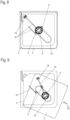
- the running grooves 22, 32 or control edges are shaped in such a way that when a moment is applied to the support element 3, it is moved from an initial position, as shown for example in Figure 8 shown, via an intermediate position as shown in the Figures 9 to 11 is shown, in which the support element 3 is rotated relative to the base 2 in one of two possible opposite directions of rotation R 1 , R 2 and displaced in the translation direction A, by further rotating in one of two possible opposite directions of rotation R 1 , R 2 and displacing against the translation direction A (shown in Figure 11 ) can be moved to a final position that is congruent with the starting position, as shown in Figure 12 is shown.
- At least one first contact element 5 which can be connected to an external power source is fastened to the guide groove 23.
- At least one second contact element 44 is arranged on the guide element 4 (as can be seen in the Figures 4 to 6 ).
- the at least one first contact element 5 is located at a position of the guide groove 23 at which the guide element 4 is in the starting and end position of the support element 3.
- the starting and end positions are shown in the Figures 8 and 12 respectively.
- the contact elements 44, 5 thus enable a power supply to electrical consumers arranged on the support element 3, which are present on or in furniture and/or household appliances arranged on the support element 3.
- Each of the first contact elements 5 has, as shown in Figure 7 is shown, preferably a holding body 51 with which the first contact element 5 is attached to the base 2, for example in a recess 24 of the base 2 adjacent to the guide groove 23, as is exemplified in Figure 4 is shown, as well as contact surfaces 52, which serve to make contact with the second contact element 44 on the guide element 4.
- FIG. 5 An exemplary embodiment of such a guide element 4 is shown in Figure 5 and Figure 6 shown as an individual representation.
- the guide element 4 here essentially consists of a cylindrical insert piece 41, which can be inserted into a guide element receptacle 33 provided for this purpose in the support element 3, and a cylindrical sliding piece 42 with a larger diameter than the diameter of the insert piece 41 and with a preferably smooth-surfaced outer casing, which slides along the inner walls of the guide groove 23 during the translational movement of the guide element 4.
- a collar 46 extends with an even larger diameter than the sliding piece 42.
- the collar 46 protrudes into a milled recess 25 on the underside of the base 2 facing away from the bearing area 21 of the base 2 and thus secures the support element 3 to the base 2 in the vertical direction.
- the guide element 4 has vertical bores in the area radially inside the outer surface of the sliding piece 42, which serve to accommodate screws for screwing the guide element 4 to the support element 3.
- the electrically conductive contact surfaces of the second contact element 44 are received in the region of the outer jacket surfaces 45 and/or an end face 43 of the collar 46 projecting beyond the sliding piece 42.
- the front surface 43 of the collar 46 is in the assembled state, as shown in the Figures 3 and 4 shown, spaced from the edge of the base 2 framing the guide groove 23.
- the contact element 44 is connected via a cable 16 to a connection 18 for supplying power to the electrical consumer arranged on the support element 3.
- a cable 16 also extends from the first contact element(s) 5, which serves for connection to the external power source (not shown here).
- a guide cam track 7 is arranged on one of the bearing areas 21, 31 and a guide element 13 guided in the guide cam track 7 is arranged on the other of the bearing areas 21, 31.
- the guide cam track 7 is attached to the support element 3 and the guide element 13 is attached to the base 2.
- a linear guide 6 fastened to the base 2 can be seen here, with at least a first connecting part 61, here designed as a guide rail, and a second connecting part 62, here designed as a running rail that can be moved on the guide rail in the translation direction A.
- the second connection part 62 is coupled to the support element 3 by means of a pivot bearing 14, so that the support element 3 is also at least partially positively guided relative to the base 2 and can be rotated in one of two possible opposite directions of rotation R1, R2 and can be moved in a predetermined translation direction A.
- the guide element 13 and the ends 71, 72 of the guide cam track 7 have electrical contact elements 8, 9.
- the contact element 8 arranged on the base 2 is connected to an external power source (not shown).
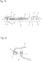
- the Figure 16 shows in a plan view a starting or end position of the support element 3, in which contact pins 91 of a second contact element 9, designed here as a plug, rest on the contact surfaces of the first contact element 8.
- a further second contact element 9 is arranged near a diagonally opposite end 72 of the guide cam track 7, so that after the translational-rotational movement of the support element 3, in which the guide element 13 has moved from the first end 71 of the guide cam track 7 to the second end 72 of the guide cam track 7, it also comes into contact with the contact pins 91 of the second contact element 9, which is designed here as a plug, and thus ensures a power supply of an electrical consumer on or at the support element 3.
- Figure 17 shows schematically an approximately 10° open position of the support element 3 relative to the base 2, in which the guide element 13 has moved away from the second contact element 9, so that in this position no power is supplied to the electrical consumer on the support element 3.
- the guide cam track 7 is hidden in this and other figures.
- Figure 15 shows an isometric individual representation of such a second contact element 9, here designed as a plug with contact pins 91 protruding from it and a cable 16 connected to the second contact element 9, as well as the guide element 13, from the bottom of which a cable 16 also protrudes, as well as the contact surface of the first contact element 8 on the outer surface 45 of the jacket of the guide element 13.
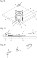
- the second contact element 9 is designed in the form of individual, separate contact elements which are positioned on the support element 3 in such a way that they are positioned in the area of the two ends 71, 72 of the guide cam track 7 and accordingly ensure a power supply to the electrical consumer on the support element 3 when the guide element 13 is retracted into the ends 71, 72.
- the guide cam track 7 is not shown for the sake of clarity.
- FIG. 21 A further embodiment of a translation-rotation arrangement according to the invention is shown in the Figures 21 to 25 shown.
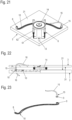
- the power supply of the electrical consumer on the support element 3 is provided here by a separate contact guide track 10 arranged in the base 2. and a sliding bolt 15 guided in the contact guide track 10 with second contact elements 9.
- an energy storage device for example in the form of at least one accumulator or capacitor, to the support element 3, so that during movement of the furniture in which the contact is interrupted, the energy supply of electrical components arranged on the support element 3 can be maintained for a certain period of time.
- the energy storage device recharges itself accordingly when contact is made in the end positions.
Landscapes
- Bearings For Parts Moving Linearly (AREA)
- Connector Housings Or Holding Contact Members (AREA)
- Transmission Devices (AREA)
Abstract
Description
- Die vorliegende Erfindung betrifft eine Translations-Rotations-Anordnung für wenigstens ein Möbel oder Haushaltsgerät gemäß dem Oberbegriff des Anspruchs 1 und gemäß dem Oberbegriff des Anspruchs 5.
- Gattungsgemäße Translations-Rotations-Anordnungen für Möbel oder Haushaltsgeräte dienen dem vereinfachten Zugriff zu schwer erreichbaren Flächen in einem Stauraum des Möbels oder Haushaltsgerätes oder auch der variablen Anordnung von Möbeln oder Haushaltsgeräten oder einer Gruppe solcher Möbel oder Haushaltsgeräte, die auf einem Tragelement einer solchen Translations-Rotations-Anordnung angeordnet sind.
- Die gleichzeitige Translations- und Rotations-Bewegung des Möbels oder Haushaltsgerätes erfolgt dabei, wie oben erwähnt, durch Anordnung des Möbels oder Haushaltsgerätes auf einem Tragelement der Translations-Rotations-Anordnung, das relativ zu einer Basis der Translations-Rotations-Anordnung zumindest teilweise gleichzeitig translatorisch und rotatorisch bewegbar gelagert ist.
- Eine solche gattungsgemäße Translations-Rotations-Anordnung ist beispielsweise aus der
WO 2021/001395 A1 oder derWO 2020/212373 A1 bekannt. - Problematisch bei solchen relativ zueinander bewegbaren Bauteilen ist die Versorgung mit elektrischer Energie von elektrischen Verbrauchern, die auf oder in dem Tragelement angeordnet sind.
- Aufgabe der vorliegenden Erfindung ist es, eine Translations-Rotations-Anordnung für wenigstens ein Möbel oder Haushaltsgerät bereitzustellen, mit dem in einfacher Weise eine Stromversorgung der auf dem oder in dem translatorisch und rotatorisch bewegten Tragelement ermöglicht ist.
- Diese Aufgabe wird durch eine Translations-Rotations-Anordnung für wenigstens ein Möbel oder Haushaltsgerät mit den Merkmalen des Anspruchs 1 sowie durch eine Translations-Rotations-Anordnung mit den Merkmalen des Anspruchs 5 bzw. 8 gelöst.
- Eine erste bevorzugte Variante einer solchen Translations-Rotations-Anordnung weist eine Basis und ein Tragelement mit einander zugewandten ebenen Lagerbereichen auf. Das Tragelement ist dabei relativ zur Basis zumindest teilweise gleichzeitig translatorisch und rotatorisch bewegbar gelagert.
- Einander zugewandte Lagerflächen der Lagerbereiche weisen jeweilige Laufrillen oder Steuerkanten auf, in bzw. an denen Wälzkörper geführt sind.
- Alternativ weist eine der einander zugewandten Lagerflächen der Lagerbereiche Laufrillen oder Steuerkanten und die andere der Lagerflächen der Lagerbereiche Kugelrollen mit in diesen geführten Kugeln auf, die in den Laufrillen bzw. entlang der Steuerkanten geführt sind.
- In beiden Varianten ist das Tragelement so relativ zur Basis zumindest teilweise zwangsgeführt in einer von zwei möglichen entgegengesetzten Drehrichtungen drehbar und in einer vorbestimmten Translationsrichtung bewegbar.
- Die Laufrillen oder Steuerkanten sind derart geformt, dass bei Momenteneinwirkung auf das Tragelement das Tragelement von einer Ausgangsposition über eine Zwischenposition, bei der das Tragelement relativ zur Basis in der einen von zwei möglichen entgegengesetzten Drehrichtungen gedreht und in Translationsrichtung verschoben ist, durch Weiterdrehen in der einen von zwei möglichen entgegengesetzten Drehrichtungen und Verschieben entgegen der Translationsrichtung in eine der Ausgangsposition deckungsgleiche Endposition bewegbar ist.
- In der Basis ist eine sich in einer Translationsrichtung erstreckende Führungsnut angeordnet. An dem Lagerbereich des Tragelements ist entsprechend ein in die Führungsnut vorstehendes Führungselement angeordnet.
- An der Führungsnut ist wenigstens ein mit einer externen Stromquelle verbindbares erstes Kontaktelement befestigt. An dem Führungselement ist wenigstens ein zweites Kontaktelement angeordnet, wobei das wenigstens eine erste Kontaktelement an einer Position der Führungsnut befestigt ist, an der sich das Führungselement in der Ausgangs- und Endposition des Tragelements befindet.
- Mit einer solchermaßen ausgebildeten Translations-Rotations-Anordnung ist in einfacher Weise eine Stromversorgung von auf oder in dem Tragelement angeordneten elektrischen Verbrauchern ermöglicht.
- Durch die Bereitstellung elektrischer Kontakte in der deckungsgleichen Ausgangs- und Endposition des Tragelements kann auf eine aufwändige Mitführung von Stromkabeln verzichtet werden.
- Dabei kann die Basis in einem Möbel- oder Haushaltsgerätekorpus angeordnet oder ausgebildet sein und das Tragelement ein Teil eines Innenkorpus darstellen.
- Alternativ kann das Tragelement als Ablage oder Plattform für die Anordnung von ggf. unterschiedlichen Möbeln ausgebildet sein.
- Andere Ausprägungen sind auch möglich. Die Basis kann auch als Sockel oder Wandhalterung ausgeführt sein.
- Vorteilhafte Weiterbildungen diese Variante sind in den Unteransprüchen angegeben.
- So sind gemäß einer bevorzugten Weiterbildung die ersten Kontaktelemente in einander gegenüberliegend an die Führungsnut angrenzenden Ausnehmungen der Basis aufgenommen.
- Dadurch ist eine dauerhaft sichere Positionierung der ersten Kontaktelemente an der Führungsnut gewährleistet.
- Gemäß einer weiteren vorteilhaften Weiterbildung sind elektrisch leitende Kontaktflächen des zweiten Kontaktelements im Bereich einer Mantelaußenfläche und/oder einer Stirnfläche eines über ein Gleitstück überstehenden Kragens des Führungselements aufgenommen, wobei die Stirnfläche des Kragens im montierten Zustand des Führungselements beabstandet zu einem die Führungsnut umrahmenden Rand der Basis ist und in der Kontaktposition des Führungselements die Kontaktflächen des zweiten Kontaktelements an Kontaktflächen der ersten Kontaktelemente anliegen.
- Die Anordnung der Kontaktelemente am Führungselement gewährleistet, dass die Kontaktelemente bei der Translationsbewegung des Führungselements in der Führungsnut nicht an Wandungen der Führungsnut schleifen und somit keinem unerwünschten Verschleiß unterliegen.
- Zur einfachen Stromversorgung eines elektrischen Verbrauchers ist das zweite Kontaktelement bevorzugt über ein Kabel mit einem Anschluss zur Stromversorgung eines am Tragelement angeordneten elektrischen Verbrauchers verbunden.
- In einer alternativen Ausführungsvariante der Translations-Rotations-Anordnung weist diese ebenfalls eine Basis und ein Tragelement mit einander zugewandten ebenen Lagerbereichen auf. Das Tragelement ist auch hier relativ zur Basis zumindest teilweise gleichzeitig translatorisch und rotatorisch bewegbar gelagert.
- Bei dieser Variante ist an einem der Lagerbereiche eine Führungskurvenbahn und an dem anderen der Lagerbereiche ein in der Führungskurvenbahn geführtes Führungselement angeordnet.
- Die Translations-Rotations-Anordnung weist des Weiteren eine Linearführung mit wenigstens einem ersten Anschlussteil und einem relativ zu diesem bewegbaren zweiten Anschlussteil auf, von denen eines ortsfest mit der Basis und das andere mittels eines Drehlagers gelagert mit dem Tragelement gekoppelt ist, so dass das Tragelement relativ zur Basis zumindest teilweise zwangsgeführt in einer von zwei möglichen entgegengesetzten Drehrichtungen drehbar und in einer vorbestimmten Translationsrichtung bewegbar ist.
- Außerdem weisen bei dieser Variante das Führungselement und die Enden der Führungskurvenbahn elektrische Kontaktelemente auf, wobei das mindestens eine an der Basis angeordnete Kontaktelement mit einer externen Stromquelle verbunden ist.
- Auch für diese alternativ ausgebildete Translations-Rotations-Anordnung ist nun in einfacher Weise eine Stromversorgung von am oder im Tragelement angeordneten elektrischen Verbrauchern ermöglicht.
- In einer vorteilhaften Weiterbildung dieser Ausführungsvariante sind die an den Enden der Führungskurvenbahn angeordneten Kontaktelemente jeweils als Stecker mit Kontaktstiften ausgebildet.
- In einer alternativen Ausführungsvariante sind an jedem der Enden der Führungskurvenbahn jeweils mindestens zwei separate Kontaktelemente angeordnet.
- In einer nochmals weiteren Ausführungsvariante ist an oder in der Basis eine mit einer externen Stromquelle verbundene Kontaktführungsbahn angeordnet, in der ein mit mindestens einem elektrischen Kontaktelement versehener, aus dem Lagerbereich des Tragelements vorstehender Gleitbolzen geführt ist. Anstelle eines Gleitbolzen kann auch ein anderes Element, beispielsweise eine Rolle, verwendet werden.
- Die Vorsehung einer solchen separaten Kontaktführungsbahn ermöglicht einer bevorzugten Ausführungsvariante, dass die Kontaktführungsbahn ausschließlich im Bereich ihrer Enden elektrisch leitende Kontaktelemente aufweist.
- In einer weiteren bevorzugten Ausführungsvariante weist die Kontaktführungsbahn ein durchgehend elektrisch leitendes Kontaktelementband auf.
- Dadurch ist eine Stromversorgung eines elektrischen Verbrauchers auch während der Translations-Rotations-Bewegung des Tragelements ermöglicht.
- Nachfolgend werden bevorzugte Ausführungsbeispiele anhand der beiliegenden Zeichnungen näher erläutert.
- Es zeigen:
- Fig. 1
- eine schematische perspektivische Explosionsdarstellung einer ersten Ausführungsvariante einer erfindungsgemäßen TranslationsRotations-Anordnung mit Laufrillen und Wälzkörpern zur Durchführung der Translations-Rotations-Bewegung,
- Figur 2
- eine schematische Draufsicht auf die Translations-Rotations-Anordnung gemäß
Figur 1 , - Figur 3
- eine Schnittansicht entlang einer in
Figur 2 mit III bezeichneten Schnittebene, - Figur 4
- eine Ausschnittsvergrößerung eines in
Figur 3 mit IV bezeichneten Bereichs zur Darstellung der Kontaktierung der ersten und zweiten Kontaktelemente, - Figur 5
- eine isometrische Einzeldarstellung des Führungselements,
- Figur 6
- eine Schnittansicht durch das Führungselement gemäß
Figur 5 , - Figur 7
- eine isometrische Einzeldarstellung eines ersten Kontaktelements,
- Figuren 8 bis 12
- der
Figur 2 entsprechende schematische Draufsichten auf die Translations-Rotations-Anordnung gemäßFigur 1 zur Darstellung einer Translations-Rotations-Bewegung des Tragelements relativ zur Basis um 90°, - Figur 13
- eine schematische perspektivische Darstellung einer alternativen Ausführungsvariante einer erfindungsgemäßen Translations-Rotations-Anordnung mit einer schienenbasierten Linearführung und in einer Führungskurvenbahn geführtem Führungselement mit daran angeordneten ersten Kontaktelementen,
- Figur 14
- eine Seitenschnittansicht durch die Translations-Rotations-Anordnung gemäß
Figur 13 , - Figur 15
- eine isometrische Einzeldarstellung eines ersten und zweiten Kontaktelements,
- Figur 16
- eine schematische Draufsicht auf die Translations-Rotations-Anordnung gemäß
Figur 13 mit Führungselement in einer ersten Kontaktstellung, - Figur 17
- eine der
Figur 16 entsprechende Darstellung in einer Offenstellung des Tragelements bei voneinander wegbewegten Kontaktelementen mit als Stecker ausgeführten zweiten Kontaktelementen, - Figuren 18 bis 20
- den
Figuren 13 bis 15 entsprechende Darstellungen einer alternativen Ausführungsvariante der Translations-Rotations-Anordnung mit separaten zweiten Kontaktelementen, - Figur 21
- eine schematische isometrische Darstellung einer weiteren Ausführungsvariante einer erfindungsgemäßen Translations-Rotations-Anordnung mit separater Kontaktführungsbahn,
- Figur 22
- eine Seitenschnittansicht durch die Translations-Rotations-Anordnung gemäß
Figur 21 , - Figur 23
- eine isometrische Einzeldarstellung der Kontaktelementbahn mit ersten Kontaktelementen und einem Gleitbolzen mit zweitem Kontaktelement,
- Figur 24
- eine schematische Draufsicht auf die Translations-Rotations-Anordnung gemäß
Figur 21 mit ersten und zweiten Kontaktelementen in Kontaktstellung und - Figur 25
- eine der
Figur 24 entsprechende Darstellung der Translations-Rotations-Anordnung in einer um ca. 10° geöffneten Offenstellung des Tragelements bei aus dem einen Ende der Kontaktelementbahn entferntem Gleitbolzen und optionalem Kontaktelementband in der Kontaktelementbahn. - In der nachfolgenden Figurenbeschreibung beziehen sich Begriffe wie oben, unten, links, rechts, vorne, hinten usw. ausschließlich auf die in den jeweiligen Figuren gewählte beispielhafte Darstellung und Position der Translations-Rotations-Anordnung, Basis, Tragelement, Kontaktelement und dergleichen. Diese Begriffe sind nicht einschränkend zu verstehen, d.h., durch verschiedene Arbeitsstellungen oder die spiegelsymmetrische Auslegung oder dergleichen können sich diese Bezüge ändern.
- Im Folgenden wird anhand der
Figuren 1-12 eine erste Ausführungsvariante einer erfindungsgemäßen Translations-Rotations-Anordnung für wenigstens ein Möbel oder Haushaltsgerät beschrieben. - Die Translations-Rotations-Anordnung weist eine Basis 2 auf, auf der ein Tragelement 3 gelagert ist. Das Möbel oder Haushaltsgerät wird dabei in der Regel auf das Tragelement 3 aufgestellt.
- Denkbar ist auch eine Gruppe von Möbeln oder Haushaltsgeräten auf einem solchen Tragelement 3 aufzustellen.
- Wie in
Figur 1 dargestellt ist, weist die Basis 2 und das Tragelement 3 einander zugewandte ebene Lagerbereiche 21, 31 auf. Das Tragelement 3 ist dabei, wie oben erwähnt, relativ zur Basis 2 gleichzeitig translatorisch und rotatorisch bewegbar gelagert. - Dazu sind bei der Ausführungsvariante der Translations-Rotations-Anordnung gemäß
Figuren 1 bis 12 in den einander zugewandten Lagerflächen der Lagerbereiche 21, 31 jeweilige Laufrillen 22, 32 vorgesehen, in denen Wälzkörper 11 geführt sind. Die Wälzkörper 11 sind dabei bevorzugt in einem Wälzkörperkäfig 12 aufgenommen. - Denkbar ist auch, anstelle der Laufrillen 22, 32 Steuerkanten an den Lagerflächen der Lagerbereiche 21, 31 vorzusehen, entlang derer die Wälzkörper 11 führbar sind.
- Denkbar ist auch, anstelle der Laufrillen 22, 32 an beiden Lagerflächen nur an einer der einander zugewandten Lagerflächen der Lagerbereiche 21, 31 Laufrillen oder Steuerkanten und an der anderen der Lagerflächen der Lagerbereiche 21, 31 Kugelrollen mit in diesen geführten Kugeln vorzusehen, wobei die Kugeln in den Laufrillen 22, 32 bzw. entlang der Steuerkanten geführt sind.
- So kann das Tragelement 3 relativ zur Basis 2 zumindest teilweise zwangsgeführt in einer von zwei möglichen entgegengesetzten Drehrichtungen R1, R2 drehbar und in einer vorbestimmten Translationsrichtung A bewegt werden.
- Die Bewegung in Translationsrichtung A wird zusätzlich durch eine in der Basis 2 sich in Translationsrichtung A erstreckende Führungsnut 23 und einer an dem Lagerbereich 31 des Tragelements 3 in die Führungsnut 23 vorstehenden Führungselement 4 geführt.
- Die Laufrillen 22, 32 bzw. Steuerkanten sind derart geformt, dass bei Momenteneinwirkung auf das Tragelement 3 dieses von einer Ausgangsposition, wie sie beispielhaft in
Figur 8 gezeigt ist, über eine Zwischenposition, wie sie in denFiguren 9 bis 11 gezeigt ist, bei der das Tragelement 3 relativ zur Basis 2 in der einen von zwei möglichen entgegengesetzten Drehrichtungen R1, R2 gedreht und in Translationsrichtung A verschoben ist, durch Weiterdrehen in der einen von zwei möglichen entgegengesetzten Drehrichtungen R1, R2 und Verschieben entgegen der Translationsrichtung A (dargestellt inFigur 11 ) in eine der Ausgangsposition deckungsgleiche Endposition bewegbar ist, wie sie inFigur 12 gezeigt ist. - Wie weiter in den
Figuren 2 bis 4 und8 bis 12 zu erkennen ist, ist an der Führungsnut 23 wenigstens ein mit einer externen Stromquelle verbindbares erstes Kontaktelement 5 befestigt. - Des Weiteren ist an dem Führungselement 4 wenigstens ein zweites Kontaktelement 44 angeordnet (zu erkennen in den
Figuren 4 bis 6 ). - Das wenigstens eine erste Kontaktelement 5 befindet sich dabei an einer Position der Führungsnut 23, an der sich das Führungselement 4 in der Ausgangsund Endposition des Tragelements 3 befindet. Die Ausgangs- und Endpositionen sind in den
Figuren 8 bzw. 12 dargestellt. - Die Kontaktelemente 44, 5 ermöglichen so eine Stromversorgung von auf dem Tragelement 3 angeordneten elektrischen Verbrauchern, die an oder in auf dem Tragelement 3 angeordneten Möbeln und/oder Haushaltsgeräten vorhanden sind.
- Jedes der ersten Kontaktelemente 5 weist, wie es in
Figur 7 dargestellt ist, vorzugsweise einen Haltekörper 51 auf, mit dem das erste Kontaktelement 5 an der Basis 2 befestigt wird, beispielsweise in einer an die Führungsnut 23 angrenzenden Ausnehmung 24 der Basis 2, wie es beispielhaft inFigur 4 dargestellt ist, sowie Kontaktflächen 52, die der Kontaktierung mit dem zweiten Kontaktelement 44 am Führungselement 4 dienen. - Eine beispielhafte Ausführungsvariante eines solchen Führungselements 4 ist in
Figur 5 undFigur 6 als Einzeldarstellung gezeigt. - Das Führungselement 4 besteht hier im Wesentlichen aus einem zylindrischen Einsteckstück 41, das in eine dazu vorgesehene Führungselementaufnahme 33 im Tragelement 3 einsteckbar ist, sowie einem zylindrischen Gleitstück 42 mit gegenüber dem Durchmesser des Einsteckstücks 41 größerem Durchmesser mit bevorzugt glattflächigem Außenmantel, der an Innenwänden der Führungsnut 23 bei der Translationsbewegung des Führungselements 4 entlanggleitet.
- Auf der dem Einsteckstück 41 abgewandten Seite des Gleitstücks 42 erstreckt sich ein Kragen 46 mit gegenüber dem Gleitstück 42 nochmals größerem Durchmesser. Der Kragen 46 steht dabei in eine Ausfräsung 25 auf der dem Lagerbereich 21 der Basis 2 abgewandten Unterseite der Basis 2 vor und sichert so in vertikaler Richtung das Tragelement 3 an der Basis 2.
- Das Führungselement 4 weist im Bereich radial innerhalb der Mantelaußenfläche des Gleitstücks 42 Vertikalbohrungen auf, die der Aufnahme von Schrauben zur Verschraubung des Führungselements 4 an dem Tragelement 3 dienen.
- Wie weiter in den
Figuren 5 und6 gut zu erkennen ist, sind die elektrisch leitenden Kontaktflächen des zweiten Kontaktelements 44 im Bereich der Mantelaußenflächen 45 und/oder einer Stirnfläche 43 des über das Gleitstück 42 überstehenden Kragens 46 aufgenommen. - Die Stirnfläche 43 des Kragens 46 ist dabei im montierten Zustand, wie es in den
Figuren 3 und4 gezeigt ist, beabstandet zu dem die Führungsnut 23 umrahmenden Rand der Basis 2. - In der Kontaktposition des Führungselements 4, wie in den
Figuren 2 ,8 und12 gezeigt, liegen die Kontaktflächen des zweiten Kontaktelements 44 an den Kontaktflächen 52 des ersten Kontaktelements 5 an. - Weiter ist, wie in
Figur 2 undFiguren 8 bis 12 dargestellt ist, das Kontaktelement 44 über ein Kabel 16 mit einem Anschluss 18 zur Stromversorgung des am Tragelement 3 angeordneten elektrischen Verbrauchers verbunden. Auch von dem bzw. den ersten Kontaktelementen 5 erstreckt sich ein Kabel 16, das dem Anschluss an die hier nicht dargestellte externe Stromquelle dient. Anhand derFiguren 13 bis 25 werden zwei weitere Ausführungsvarianten einer erfindungsgemäßen Translations-Rotations-Anordnung beschrieben. - Bei dieser Translations-Rotations-Anordnung sind anstelle der Laufrillen 22, 32 in den Lagerbereichen 21, 31 der Basis 2 bzw. des Tragelements 3 an einem der Lagerbereiche 21, 31 eine Führungskurvenbahn 7 und an dem anderen der Lagerbereiche 21, 31 ein in der Führungskurvenbahn 7 geführtes Führungselement 13 angeordnet.
- Bei der in den
Figuren 13 bis 25 gezeigten Ausführungsvariante ist die Führungskurvenbahn 7 am Tragelement 3 und das Führungselement 13 an der Basis 2 befestigt. - Weiter ist hier eine an der Basis 2 befestigte Linearführung 6 zu erkennen, mit wenigstens einem ersten Anschlussteil 61, hier ausgebildet als Führungsschiene, und einem zweiten Anschlussteil 62, hier ausgebildet als auf der Führungsschiene in Translationsrichtung A verfahrbare Laufschiene.
- Das zweite Anschlussteil 62 ist in den in den Figuren gezeigten Ausführungsvarianten mittels eines Drehlagers 14 mit dem Tragelement 3 gekoppelt, so dass das Tragelement 3 auch hier relativ zur Basis 2 zumindest teilweise zwangsgeführt in einer von zwei möglichen entgegengesetzten Drehrichtungen R1, R2 drehbar und in einer vorbestimmten Translationsrichtung A bewegbar ist.
- Wie weiter insbesondere in den
Figuren 13 und14 gut zu erkennen ist, weisen hier das Führungselement 13 und die Enden 71, 72 der Führungskurvenbahn 7 elektrische Kontaktelemente 8, 9 auf. - Das an der Basis 2 angeordnete Kontaktelement 8 ist dabei mit einer externen Stromquelle (nicht gezeigt) verbunden.
- Die
Figur 16 zeigt in einer Draufsicht eine Ausgangs- oder Endposition des Tragelements 3, bei der Kontaktstifte 91 eines hier als Stecker ausgebildeten zweiten Kontaktelements 9 an den Kontaktflächen des ersten Kontaktelements 8 anliegen. - Ein weiteres zweites Kontaktelement 9 ist bei dieser Ausführungsvariante nahe eines diagonal gegenüberliegenden Endes 72 der Führungskurvenbahn 7 angeordnet, so dass nach erfolgter Translations-Rotations-Bewegung des Tragelements 3, bei der das Führungselement 13 vom ersten Ende 71 der Führungskurvenbahn 7 zum zweiten Ende 72 der Führungskurvenbahn 7 verfahren ist, auch dort in Kontakt mit den Kontaktstiften 91 des hier als Stecker ausgebildeten zweiten Kontaktelements 9 gelangt und so eine Stromversorgung eines elektrischen Verbrauchers auf oder an dem Tragelement 3 gewährleistet.
-
Figur 17 zeigt schematisch eine etwa 10°- Offenstellung des Tragelements 3 relativ zur Basis 2, bei der das Führungselement 13 sich von dem zweiten Kontaktelement 9 wegbewegt hat, so dass in dieser Positionsstellung keine Stromversorgung des elektrischen Verbrauchers am Tragelement 3 stattfindet. Aus Übersichtsgründen ist bei dieser und weiteren Figuren die Führungskurvenbahn 7 ausgeblendet. -
Figur 15 zeigt eine isometrische Einzeldarstellung eine solchen zweiten Kontaktelements 9, hier als Stecker ausgebildet mit aus diesem vorstehenden Kontaktstiften 91 und einem an das zweite Kontaktelement 9 angeschlossenen Kabel 16 sowie das Führungselement 13, aus dessen Boden ebenfalls ein Kabel 16 vorsteht sowie der Kontaktfläche des ersten Kontaktelements 8 an der Mantelaußenfläche 45 des Führungselements 13. - Im Gegensatz zu dem als Stecker ausgebildeten zweiten Kontaktelement 9 gemäß
Figuren 13 bis 17 ist bei denFiguren 18 bis 20 das zweite Kontaktelement 9 in Gestalt einzelner separater Kontaktelemente ausgebildet, die an dem Tragelement 3 entsprechend so positioniert sind, dass diese in den im Bereich der beiden Enden 71, 72 der Führungskurvenbahn 7 positioniert sind und entsprechend bei in die Enden 71, 72 eingefahrenem Führungselement 13 eine Stromversorgung des elektrischen Verbrauchers am Tragelement 3 gewährleisten. Auch hier ist aus Übersichtlichkeit die Führungskurvenbahn 7 nicht gezeigt. - Ein nochmals weitere Ausführungsvariante einer erfindungsgemäßen Translations-Rotations-Anordnung ist in den
Figuren 21 bis 25 dargestellt. - Auch hier wird die Translations-Rotations-Bewegung durch die bereits zuvor beschriebene Linearführung 6 und das Führungselement 13, das in einer Führungskurvenbahn 7 geführt ist, gewährleistet.
- Die Stromversorgung des elektrischen Verbrauchers am Tragelement 3 wird hier durch eine separate, in der Basis 2 angeordnete Kontaktführungsbahn 10 und ein in der Kontaktführungsbahn 10 geführten Gleitbolzen 15 mit zweiten Kontaktelementen 9 gewährleistet.
- Denkbar ist bei dieser Ausführungsvariante neben einer Anordnung von ersten Kontaktelementen 8 an den Enden der Kontaktführungsbahn 10 auch die Vorsehung eines durchgehend elektrisch leitenden Kontaktelementbandes 17 in der Kontaktführungsbahn 10, so dass eine elektrische Stromversorgung auch während der Translations-Rotations-Bewegung des Tragelements 3 relativ zur Basis 2 ermöglicht ist.
- Ebenfalls denkbar ist die Festlegung eines Energiespeichers, beispielsweise in Gestalt wenigstens eines Akkumulators oder Kondensators, am Tragelement 3, so dass während der Bewegung des Möbels, bei dem die Kontaktierung unterbrochen ist, die Energiezufuhr von auf dem Tragelement 3 angeordneten elektrischen Bauteilen über einen gewissen Zeitraum aufrechterhalten werden kann. Der Energiespeicher lädt sich entsprechend bei Kontaktierung in den Endpositionen wieder auf.
-
- 2
- Basis
- 21
- Lagerbereich
- 22
- Laufrille
- 23
- Führungsnut
- 24
- Ausnehmung
- 25
- Ausfräsung
- 3
- Tragelement
- 31
- Lagerbereich
- 32
- Laufrille
- 33
- Führungselementaufnahme
- 4
- Führungselement
- 41
- Einsteckstück
- 42
- Gleitstück
- 43
- Stirnfläche
- 44
- zweites Kontaktelement
- 45
- Mantelaußenfläche
- 46
- Kragen
- 5
- erstes Kontaktelement
- 51
- Haltekörper
- 52
- Kontaktfläche
- 6
- Linearführung
- 61
- erstes Anschlussteil
- 62
- zweites Anschlussteil
- 7
- Führungskurvenbahn
- 71
- erstes Ende
- 72
- zweites Ende
- 8
- Kontaktelement
- 9
- Kontaktelement
- 91
- Kontaktstift
- 10
- Kontaktführungsbahn
- 11
- Wälzkörper
- 12
- Wälzkörperkäfig
- 13
- Führungselement
- 14
- Drehlager
- 15
- Gleitbolzen
- 16
- Kabel
- 17
- Kontaktelementband
- 18
- Anschluss
- R1, R2
- Drehrichtung
- A
- Translationsrichtung
Claims (11)
- Translations-Rotations-Anordnung für wenigstens ein Möbel oder Haushaltsgerät, aufweisend:- eine Basis (2) und ein Tragelement (3) mit einander zugewandten ebenen Lagerbereichen (21, 31),- wobei das Tragelement (3) relativ zur Basis (2) zumindest teilweise gleichzeitig translatorisch und rotatorisch bewegbar gelagert ist,- wobei einander zugewandte Lagerflächen der Lagerbereiche (21, 31) jeweilige Laufrillen (22, 32) aufweisen, in denen Wälzkörper (11) geführt sind oder eine der einander zugewandten Lagerflächen der Lagerbereiche (21, 31) Laufrillen (22, 32) oder Steuerkanten und die andere der Lagerflächen der Lagerbereiche (21, 31) Kugelrollen mit in diesen geführten Kugeln aufweist, die in den Laufrillen (22, 32) bzw. entlang der Steuerkanten geführt sind, so dass das Tragelement (3) relativ zur Basis (2) zumindest teilweise zwangsgeführt in einer von zwei möglichen entgegengesetzten Drehrichtungen (R1, R2) drehbar und in einer vorbestimmten Translationsrichtung (A) bewegbar ist,- wobei die Laufrillen (22, 32) oder Steuerkanten derart geformt sind, dass bei Momenteneinwirkung auf das Tragelement (3) das Tragelement (3) von einer Ausgangsposition über eine Zwischenposition, bei der das Tragelement (3) relativ zur Basis (2) in der einen von zwei möglichen entgegengesetzten Drehrichtungen (R1, R2) gedreht und in Translationsrichtung (A) verschoben ist, durch Weiterdrehen in der einen von zwei möglichen entgegengesetzten Drehrichtungen (R1, R2) und Verschieben entgegen der Translationsrichtung (A) in eine der Ausgangsposition deckungsgleiche Endposition bewegbar ist,- wobei in der Basis (2) eine sich in einer Translationsrichtung (A) erstreckende Führungsnut (23) und an dem Lagerbereich (31) des Tragelements (3) ein in die Führungsnut (23) vorstehendes Führungselement (4) angeordnet ist,dadurch gekennzeichnet, dass- an der Führungsnut (23) wenigstens ein mit einer externen Stromquelle verbindbares erstes Kontaktelement (5) befestigt ist und- an dem Führungselement (4) wenigstens ein zweites Kontaktelement (44) angeordnet ist,- wobei das wenigstens eine erste Kontaktelement (5) an einer Position der Führungsnut (23) befestigt ist, an der sich das Führungselement (4) in der Ausgangs- und Endposition des Tragelements (3) befindet.
- Translations-Rotations-Anordnung nach Anspruch 1, dadurch gekennzeichnet, dass die ersten Kontaktelemente (5) in einander gegenüberliegend an die Führungsnut (23) angrenzenden Ausnehmungen (24) der Basis (2) aufgenommen sind.
- Translations-Rotations-Anordnung nach Anspruch 1 oder 2, dadurch gekennzeichnet, dass elektrisch leitende Kontaktflächen des zweiten Kontaktelements (44) im Bereich einer Mantelaußenfläche (45) und/oder einer Stirnfläche (43) eines über ein Gleitstück (42) überstehenden Kragens (46) des Führungselements (4) aufgenommen sind.
- Translations-Rotations-Anordnung nach einem der vorstehenden Ansprüche, dadurch gekennzeichnet, dass das zweite Kontaktelement (44) über ein Kabel (16) mit einem Anschluss (18) zur Stromversorgung eines am Tragelement (3) angeordneten elektrischen Verbrauchers verbunden ist.
- Translations-Rotations-Anordnung für wenigstens ein Möbel oder Haushaltsgerät, aufweisend:- eine Basis (2) und ein Tragelement (3) mit einander zugewandten ebenen Lagerbereichen (21, 31),- wobei das Tragelement (3) relativ zur Basis (2) zumindest teilweise gleichzeitig translatorisch und rotatorisch bewegbar gelagert ist,- wobei an einem der Lagerbereiche (21, 31) eine Führungskurvenbahn (7) und an dem anderen der Lagerbereiche (21, 31) ein in der Führungskurvenbahn (7) geführtes Führungselement (13) angeordnet ist,- eine Linearführung (6) mit wenigstens einem ersten Anschlussteil (61) und einem relativ zu diesem bewegbaren zweiten Anschlussteil (62), von denen eines ortsfest mit der Basis (2) und das andere mittels eines Drehlagers (14) gelagert mit dem Tragelement (3) gekoppelt ist, so dass das Tragelement (3) relativ zur Basis (2) zumindest teilweise zwangsgeführt in einer von zwei möglichen entgegengesetzten Drehrichtungen (R1, R2) drehbar und in einer vorbestimmten Translationsrichtung (A) bewegbar ist,dadurch gekennzeichnet, dass- das Führungselement (13) und die Enden (71, 72) der Führungskurvenbahn (7) elektrische Kontaktelemente (8, 9) aufweisen,- wobei das mindestens eine an der Basis (2) angeordnete Kontaktelement (8) mit einer externen Stromquelle verbunden ist.
- Translations-Rotations-Anordnung nach Anspruch 5, dadurch gekennzeichnet, dass die an den Enden (71, 72) der Führungskurvenbahn (7) angeordneten Kontaktelemente (9) jeweils als Stecker mit Kontaktstiften (91) ausgebildet sind.
- Translations-Rotations-Anordnung nach Anspruch 5, dadurch gekennzeichnet, dass an jedem der Enden (71, 72) der Führungskurvenbahn (7) jeweils mindestens zwei Kontaktelemente (9) angeordnet sind.
- Translations-Rotations-Anordnung nach dem Oberbegriff des Anspruchs 5, dadurch gekennzeichnet, dass
an oder in der Basis (2) eine mit einer externen Stromquelle verbundene Kontaktführungsbahn (10) angeordnet ist, in der ein mit mindestens einem elektrischen Kontaktelement (9) versehener, aus dem Lagerbereich (31) des Tragelements (3) vorstehender Gleitbolzen (15) geführt ist. - Translations-Rotations-Anordnung nach Anspruch 8, dadurch gekennzeichnet, dass die Kontaktführungsbahn (10) ausschließlich im Bereich ihrer Enden elektrisch leitende Kontaktelemente (8) aufweist.
- Translations-Rotations-Anordnung nach Anspruch 8, dadurch gekennzeichnet, dass die Kontaktführungsbahn (10) ein durchgehend elektrisch leitendes Kontaktelementband (17) aufweist.
- Translations-Rotations-Anordnung nach einem der vorstehenden Ansprüche, dadurch gekennzeichnet, dass am Tragelement (3) ein Energiespeicher festgelegt ist, der mit dem am Tragelement (3) angeordneten zweiten Kontaktelement (44) bzw. dem Kontaktelement (9) bzw. dem Gleitbolzen (15) verbunden ist.
Applications Claiming Priority (1)
| Application Number | Priority Date | Filing Date | Title |
|---|---|---|---|
| DE102023107074.6A DE102023107074A1 (de) | 2023-03-21 | 2023-03-21 | Translations-Rotations-Anordnung für wenigstens ein Möbel oder Haushaltsgerät |
Publications (2)
| Publication Number | Publication Date |
|---|---|
| EP4434395A1 true EP4434395A1 (de) | 2024-09-25 |
| EP4434395B1 EP4434395B1 (de) | 2025-07-23 |
Family
ID=90368407
Family Applications (1)
| Application Number | Title | Priority Date | Filing Date |
|---|---|---|---|
| EP24164799.9A Active EP4434395B1 (de) | 2023-03-21 | 2024-03-20 | Translations-rotations-anordnung für wenigstens ein möbel oder haushaltsgerät |
Country Status (3)
| Country | Link |
|---|---|
| EP (1) | EP4434395B1 (de) |
| CN (1) | CN118680394A (de) |
| DE (1) | DE102023107074A1 (de) |
Citations (4)
| Publication number | Priority date | Publication date | Assignee | Title |
|---|---|---|---|---|
| WO2020007525A1 (de) * | 2018-07-04 | 2020-01-09 | Paul Hettich Gmbh & Co. Kg | Ablageboden für ein möbel oder haushaltsgerät |
| WO2020212373A1 (de) | 2019-04-15 | 2020-10-22 | Paul Hettich Gmbh & Co. Kg | Möbelelement |
| WO2021001395A1 (de) | 2019-07-04 | 2021-01-07 | Paul Hettich Gmbh & Co. Kg | Ablagevorrichtung und möbel oder haushaltsgerät |
| DE102021101535A1 (de) * | 2021-01-25 | 2022-07-28 | Paul Hettich Gmbh & Co. Kg | Möbelelement |
Family Cites Families (4)
| Publication number | Priority date | Publication date | Assignee | Title |
|---|---|---|---|---|
| CH517467A (de) * | 1971-05-28 | 1972-01-15 | Rebmann Otto | Traggestell mit mehreren Tablaren |
| DE20017048U1 (de) * | 2000-10-02 | 2000-12-21 | Finkeldei Naturmöbel GmbH & Co KG, 33442 Herzebrock-Clarholz | Eckschrank mit Karussell |
| WO2005007514A2 (en) * | 2003-06-24 | 2005-01-27 | Pi Squared Design, Inc. | Method and apparatus for movable structure having alternative accessible sides |
| DE202005008843U1 (de) * | 2005-06-03 | 2006-10-12 | Ninkaplast Gmbh | Drehboden für eine Eckschrankkarussel |
-
2023
- 2023-03-21 DE DE102023107074.6A patent/DE102023107074A1/de active Pending
-
2024
- 2024-03-20 EP EP24164799.9A patent/EP4434395B1/de active Active
- 2024-03-20 CN CN202410319254.3A patent/CN118680394A/zh active Pending
Patent Citations (4)
| Publication number | Priority date | Publication date | Assignee | Title |
|---|---|---|---|---|
| WO2020007525A1 (de) * | 2018-07-04 | 2020-01-09 | Paul Hettich Gmbh & Co. Kg | Ablageboden für ein möbel oder haushaltsgerät |
| WO2020212373A1 (de) | 2019-04-15 | 2020-10-22 | Paul Hettich Gmbh & Co. Kg | Möbelelement |
| WO2021001395A1 (de) | 2019-07-04 | 2021-01-07 | Paul Hettich Gmbh & Co. Kg | Ablagevorrichtung und möbel oder haushaltsgerät |
| DE102021101535A1 (de) * | 2021-01-25 | 2022-07-28 | Paul Hettich Gmbh & Co. Kg | Möbelelement |
Also Published As
| Publication number | Publication date |
|---|---|
| CN118680394A (zh) | 2024-09-24 |
| DE102023107074A1 (de) | 2024-09-26 |
| EP4434395B1 (de) | 2025-07-23 |
Similar Documents
| Publication | Publication Date | Title |
|---|---|---|
| EP4233641B1 (de) | Tisch | |
| EP3599936B1 (de) | Vorrichtung zur rotatorischen und translatorischen bewegung eines gegenstands | |
| DE102019132207A1 (de) | Möbelelement | |
| DE10113510A1 (de) | Walzenkäfig, direkt wirkende Führungseinrichtung und Walzenschraube, die den Walzenkäfig verwendet | |
| DE102015009989A1 (de) | Kabelklemmvorrichtung zur Aufweitung für Schirmgeflechten von Kabeln | |
| EP4280912A1 (de) | Möbelelement | |
| DE1575692A1 (de) | Gleitvorrichtung | |
| EP4434395B1 (de) | Translations-rotations-anordnung für wenigstens ein möbel oder haushaltsgerät | |
| DE202007013947U1 (de) | Kühl- und/oder Gefriergerät | |
| DE60200220T2 (de) | Elektrischer Steckanschluss mit Verschlussbuchsenblenden und Baureihe mit einem solchen Steckanschluss | |
| EP2356347A1 (de) | Wälzkörperkäfig für eine möbelauszugsführung | |
| EP4489616A1 (de) | Anordnung eines trägerelements und einer ablage | |
| DE102021131825A1 (de) | Möbel oder Haushaltsgerät | |
| EP4514178B1 (de) | Führungsbeschlag und möbel- oder haushaltsgeräteelement | |
| DE102005037323A1 (de) | Linearkugellager mit Umlaufführung | |
| DE4432821A1 (de) | Ausziehführung | |
| DE102022124143A1 (de) | Translations-Rotations-Beschlag und Möbel- oder Haushaltsgeräteelement | |
| DE102021131827A1 (de) | Möbel oder Haushaltsgerät | |
| DE102021131826A1 (de) | Vorrichtung zur rotatorischen und translatorischen Bewegung | |
| DE19653637C2 (de) | Elektrischer Schalter | |
| EP4608207A1 (de) | Translations-rotations-anordnung und möbel- oder haushaltsgeräteelement | |
| EP4719130A1 (de) | Möbelelement | |
| DE102021131828A1 (de) | Vorrichtung zur rotatorischen und translatorischen Bewegung einer Ablage relativ zu einer Trägerplatte | |
| WO2025168592A1 (de) | Translations-rotations-beschlag | |
| DE102023124025A1 (de) | Führungslager und Möbel- oder Haushaltsgeräteelement |
Legal Events
| Date | Code | Title | Description |
|---|---|---|---|
| PUAI | Public reference made under article 153(3) epc to a published international application that has entered the european phase |
Free format text: ORIGINAL CODE: 0009012 |
|
| STAA | Information on the status of an ep patent application or granted ep patent |
Free format text: STATUS: THE APPLICATION HAS BEEN PUBLISHED |
|
| AK | Designated contracting states |
Kind code of ref document: A1 Designated state(s): AL AT BE BG CH CY CZ DE DK EE ES FI FR GB GR HR HU IE IS IT LI LT LU LV MC ME MK MT NL NO PL PT RO RS SE SI SK SM TR |
|
| STAA | Information on the status of an ep patent application or granted ep patent |
Free format text: STATUS: REQUEST FOR EXAMINATION WAS MADE |
|
| 17P | Request for examination filed |
Effective date: 20241028 |
|
| RBV | Designated contracting states (corrected) |
Designated state(s): AL AT BE BG CH CY CZ DE DK EE ES FI FR GB GR HR HU IE IS IT LI LT LU LV MC ME MK MT NL NO PL PT RO RS SE SI SK SM TR |
|
| GRAP | Despatch of communication of intention to grant a patent |
Free format text: ORIGINAL CODE: EPIDOSNIGR1 |
|
| STAA | Information on the status of an ep patent application or granted ep patent |
Free format text: STATUS: GRANT OF PATENT IS INTENDED |
|
| RIC1 | Information provided on ipc code assigned before grant |
Ipc: A47B 96/02 20060101ALI20250217BHEP Ipc: A47B 49/00 20060101AFI20250217BHEP |
|
| INTG | Intention to grant announced |
Effective date: 20250307 |
|
| GRAS | Grant fee paid |
Free format text: ORIGINAL CODE: EPIDOSNIGR3 |
|
| GRAA | (expected) grant |
Free format text: ORIGINAL CODE: 0009210 |
|
| STAA | Information on the status of an ep patent application or granted ep patent |
Free format text: STATUS: THE PATENT HAS BEEN GRANTED |
|
| P01 | Opt-out of the competence of the unified patent court (upc) registered |
Free format text: CASE NUMBER: APP_25864/2025 Effective date: 20250530 |
|
| AK | Designated contracting states |
Kind code of ref document: B1 Designated state(s): AL AT BE BG CH CY CZ DE DK EE ES FI FR GB GR HR HU IE IS IT LI LT LU LV MC ME MK MT NL NO PL PT RO RS SE SI SK SM TR |
|
| REG | Reference to a national code |
Ref country code: GB Ref legal event code: FG4D Free format text: NOT ENGLISH |
|
| REG | Reference to a national code |
Ref country code: CH Ref legal event code: EP |
|
| REG | Reference to a national code |
Ref country code: DE Ref legal event code: R096 Ref document number: 502024000114 Country of ref document: DE |
|
| REG | Reference to a national code |
Ref country code: IE Ref legal event code: FG4D Free format text: LANGUAGE OF EP DOCUMENT: GERMAN |
|
| REG | Reference to a national code |
Ref country code: NL Ref legal event code: MP Effective date: 20250723 |
|
| PG25 | Lapsed in a contracting state [announced via postgrant information from national office to epo] |
Ref country code: PT Free format text: LAPSE BECAUSE OF FAILURE TO SUBMIT A TRANSLATION OF THE DESCRIPTION OR TO PAY THE FEE WITHIN THE PRESCRIBED TIME-LIMIT Effective date: 20251124 |
|
| PG25 | Lapsed in a contracting state [announced via postgrant information from national office to epo] |
Ref country code: NL Free format text: LAPSE BECAUSE OF FAILURE TO SUBMIT A TRANSLATION OF THE DESCRIPTION OR TO PAY THE FEE WITHIN THE PRESCRIBED TIME-LIMIT Effective date: 20250723 |
|
| PG25 | Lapsed in a contracting state [announced via postgrant information from national office to epo] |
Ref country code: IS Free format text: LAPSE BECAUSE OF FAILURE TO SUBMIT A TRANSLATION OF THE DESCRIPTION OR TO PAY THE FEE WITHIN THE PRESCRIBED TIME-LIMIT Effective date: 20251123 |
|
| PG25 | Lapsed in a contracting state [announced via postgrant information from national office to epo] |
Ref country code: NO Free format text: LAPSE BECAUSE OF FAILURE TO SUBMIT A TRANSLATION OF THE DESCRIPTION OR TO PAY THE FEE WITHIN THE PRESCRIBED TIME-LIMIT Effective date: 20251023 |
|
| REG | Reference to a national code |
Ref country code: LT Ref legal event code: MG9D |
|
| PG25 | Lapsed in a contracting state [announced via postgrant information from national office to epo] |
Ref country code: FI Free format text: LAPSE BECAUSE OF FAILURE TO SUBMIT A TRANSLATION OF THE DESCRIPTION OR TO PAY THE FEE WITHIN THE PRESCRIBED TIME-LIMIT Effective date: 20250723 |
|
| PG25 | Lapsed in a contracting state [announced via postgrant information from national office to epo] |
Ref country code: HR Free format text: LAPSE BECAUSE OF FAILURE TO SUBMIT A TRANSLATION OF THE DESCRIPTION OR TO PAY THE FEE WITHIN THE PRESCRIBED TIME-LIMIT Effective date: 20250723 |
|
| PG25 | Lapsed in a contracting state [announced via postgrant information from national office to epo] |
Ref country code: GR Free format text: LAPSE BECAUSE OF FAILURE TO SUBMIT A TRANSLATION OF THE DESCRIPTION OR TO PAY THE FEE WITHIN THE PRESCRIBED TIME-LIMIT Effective date: 20251024 |
|
| PG25 | Lapsed in a contracting state [announced via postgrant information from national office to epo] |
Ref country code: SE Free format text: LAPSE BECAUSE OF FAILURE TO SUBMIT A TRANSLATION OF THE DESCRIPTION OR TO PAY THE FEE WITHIN THE PRESCRIBED TIME-LIMIT Effective date: 20250723 |
|
| PG25 | Lapsed in a contracting state [announced via postgrant information from national office to epo] |
Ref country code: LV Free format text: LAPSE BECAUSE OF FAILURE TO SUBMIT A TRANSLATION OF THE DESCRIPTION OR TO PAY THE FEE WITHIN THE PRESCRIBED TIME-LIMIT Effective date: 20250723 |
|
| PG25 | Lapsed in a contracting state [announced via postgrant information from national office to epo] |
Ref country code: PL Free format text: LAPSE BECAUSE OF FAILURE TO SUBMIT A TRANSLATION OF THE DESCRIPTION OR TO PAY THE FEE WITHIN THE PRESCRIBED TIME-LIMIT Effective date: 20250723 Ref country code: BG Free format text: LAPSE BECAUSE OF FAILURE TO SUBMIT A TRANSLATION OF THE DESCRIPTION OR TO PAY THE FEE WITHIN THE PRESCRIBED TIME-LIMIT Effective date: 20250723 |
|
| PG25 | Lapsed in a contracting state [announced via postgrant information from national office to epo] |
Ref country code: RS Free format text: LAPSE BECAUSE OF FAILURE TO SUBMIT A TRANSLATION OF THE DESCRIPTION OR TO PAY THE FEE WITHIN THE PRESCRIBED TIME-LIMIT Effective date: 20251023 |
|
| PG25 | Lapsed in a contracting state [announced via postgrant information from national office to epo] |
Ref country code: ES Free format text: LAPSE BECAUSE OF FAILURE TO SUBMIT A TRANSLATION OF THE DESCRIPTION OR TO PAY THE FEE WITHIN THE PRESCRIBED TIME-LIMIT Effective date: 20250723 |
|
| PG25 | Lapsed in a contracting state [announced via postgrant information from national office to epo] |
Ref country code: SM Free format text: LAPSE BECAUSE OF FAILURE TO SUBMIT A TRANSLATION OF THE DESCRIPTION OR TO PAY THE FEE WITHIN THE PRESCRIBED TIME-LIMIT Effective date: 20250723 |
|
| PG25 | Lapsed in a contracting state [announced via postgrant information from national office to epo] |
Ref country code: DK Free format text: LAPSE BECAUSE OF FAILURE TO SUBMIT A TRANSLATION OF THE DESCRIPTION OR TO PAY THE FEE WITHIN THE PRESCRIBED TIME-LIMIT Effective date: 20250723 |
|
| PGFP | Annual fee paid to national office [announced via postgrant information from national office to epo] |
Ref country code: DE Payment date: 20260320 Year of fee payment: 3 |
|
| PGFP | Annual fee paid to national office [announced via postgrant information from national office to epo] |
Ref country code: AT Payment date: 20260301 Year of fee payment: 3 |
|
| PG25 | Lapsed in a contracting state [announced via postgrant information from national office to epo] |
Ref country code: IT Free format text: LAPSE BECAUSE OF FAILURE TO SUBMIT A TRANSLATION OF THE DESCRIPTION OR TO PAY THE FEE WITHIN THE PRESCRIBED TIME-LIMIT Effective date: 20250723 |
|
| PG25 | Lapsed in a contracting state [announced via postgrant information from national office to epo] |
Ref country code: CZ Free format text: LAPSE BECAUSE OF FAILURE TO SUBMIT A TRANSLATION OF THE DESCRIPTION OR TO PAY THE FEE WITHIN THE PRESCRIBED TIME-LIMIT Effective date: 20250723 |
|
| PG25 | Lapsed in a contracting state [announced via postgrant information from national office to epo] |
Ref country code: SK Free format text: LAPSE BECAUSE OF FAILURE TO SUBMIT A TRANSLATION OF THE DESCRIPTION OR TO PAY THE FEE WITHIN THE PRESCRIBED TIME-LIMIT Effective date: 20250723 Ref country code: EE Free format text: LAPSE BECAUSE OF FAILURE TO SUBMIT A TRANSLATION OF THE DESCRIPTION OR TO PAY THE FEE WITHIN THE PRESCRIBED TIME-LIMIT Effective date: 20250723 |