EP4432431A2 - Batterieabdeckplatte und batterie damit - Google Patents
Batterieabdeckplatte und batterie damit Download PDFInfo
- Publication number
- EP4432431A2 EP4432431A2 EP23188096.4A EP23188096A EP4432431A2 EP 4432431 A2 EP4432431 A2 EP 4432431A2 EP 23188096 A EP23188096 A EP 23188096A EP 4432431 A2 EP4432431 A2 EP 4432431A2
- Authority
- EP
- European Patent Office
- Prior art keywords
- cover plate
- hole
- battery
- battery cover
- adhesive film
- Prior art date
- Legal status (The legal status is an assumption and is not a legal conclusion. Google has not performed a legal analysis and makes no representation as to the accuracy of the status listed.)
- Pending
Links
- 239000004831 Hot glue Substances 0.000 claims abstract description 45
- 229910052751 metal Inorganic materials 0.000 claims description 30
- 239000002184 metal Substances 0.000 claims description 30
- 239000004033 plastic Substances 0.000 claims description 25
- 238000007789 sealing Methods 0.000 claims description 23
- 239000007788 liquid Substances 0.000 claims description 17
- 239000002313 adhesive film Substances 0.000 claims description 13
- 238000002347 injection Methods 0.000 claims description 10
- 239000007924 injection Substances 0.000 claims description 10
- PXHVJJICTQNCMI-UHFFFAOYSA-N Nickel Chemical compound [Ni] PXHVJJICTQNCMI-UHFFFAOYSA-N 0.000 claims description 8
- 230000004927 fusion Effects 0.000 claims description 7
- 238000009423 ventilation Methods 0.000 claims description 7
- RYGMFSIKBFXOCR-UHFFFAOYSA-N Copper Chemical compound [Cu] RYGMFSIKBFXOCR-UHFFFAOYSA-N 0.000 claims description 6
- XEEYBQQBJWHFJM-UHFFFAOYSA-N Iron Chemical compound [Fe] XEEYBQQBJWHFJM-UHFFFAOYSA-N 0.000 claims description 6
- 229910052782 aluminium Inorganic materials 0.000 claims description 6
- XAGFODPZIPBFFR-UHFFFAOYSA-N aluminium Chemical compound [Al] XAGFODPZIPBFFR-UHFFFAOYSA-N 0.000 claims description 6
- 229910052802 copper Inorganic materials 0.000 claims description 6
- 239000010949 copper Substances 0.000 claims description 6
- 230000002093 peripheral effect Effects 0.000 claims description 5
- 229910052759 nickel Inorganic materials 0.000 claims description 4
- 239000004642 Polyimide Substances 0.000 claims description 3
- BQCADISMDOOEFD-UHFFFAOYSA-N Silver Chemical compound [Ag] BQCADISMDOOEFD-UHFFFAOYSA-N 0.000 claims description 3
- RTAQQCXQSZGOHL-UHFFFAOYSA-N Titanium Chemical compound [Ti] RTAQQCXQSZGOHL-UHFFFAOYSA-N 0.000 claims description 3
- QCWXUUIWCKQGHC-UHFFFAOYSA-N Zirconium Chemical compound [Zr] QCWXUUIWCKQGHC-UHFFFAOYSA-N 0.000 claims description 3
- 239000003822 epoxy resin Substances 0.000 claims description 3
- 229910052742 iron Inorganic materials 0.000 claims description 3
- 239000000463 material Substances 0.000 claims description 3
- 229920000647 polyepoxide Polymers 0.000 claims description 3
- 229920001721 polyimide Polymers 0.000 claims description 3
- 229910052709 silver Inorganic materials 0.000 claims description 3
- 239000004332 silver Substances 0.000 claims description 3
- 239000010936 titanium Substances 0.000 claims description 3
- 229910052719 titanium Inorganic materials 0.000 claims description 3
- 229910052726 zirconium Inorganic materials 0.000 claims description 3
- 239000000853 adhesive Substances 0.000 claims description 2
- 230000001070 adhesive effect Effects 0.000 claims description 2
- 230000009471 action Effects 0.000 abstract description 3
- 238000003825 pressing Methods 0.000 abstract description 3
- 230000000694 effects Effects 0.000 description 6
- 239000003792 electrolyte Substances 0.000 description 6
- 230000000712 assembly Effects 0.000 description 5
- 238000000429 assembly Methods 0.000 description 5
- 230000009286 beneficial effect Effects 0.000 description 3
- 238000004880 explosion Methods 0.000 description 2
- 238000000034 method Methods 0.000 description 2
- 230000008569 process Effects 0.000 description 2
- 239000000243 solution Substances 0.000 description 2
- 229910000838 Al alloy Inorganic materials 0.000 description 1
- 229910000881 Cu alloy Inorganic materials 0.000 description 1
- 229910000640 Fe alloy Inorganic materials 0.000 description 1
- FYYHWMGAXLPEAU-UHFFFAOYSA-N Magnesium Chemical compound [Mg] FYYHWMGAXLPEAU-UHFFFAOYSA-N 0.000 description 1
- 229910000861 Mg alloy Inorganic materials 0.000 description 1
- 229910000990 Ni alloy Inorganic materials 0.000 description 1
- NJFMNPFATSYWHB-UHFFFAOYSA-N ac1l9hgr Chemical compound [Fe].[Fe] NJFMNPFATSYWHB-UHFFFAOYSA-N 0.000 description 1
- 230000002411 adverse Effects 0.000 description 1
- 230000007797 corrosion Effects 0.000 description 1
- 238000005260 corrosion Methods 0.000 description 1
- 230000007547 defect Effects 0.000 description 1
- 238000007599 discharging Methods 0.000 description 1
- 238000004146 energy storage Methods 0.000 description 1
- 238000005516 engineering process Methods 0.000 description 1
- 238000009413 insulation Methods 0.000 description 1
- 230000003993 interaction Effects 0.000 description 1
- 230000001788 irregular Effects 0.000 description 1
- 229910052749 magnesium Inorganic materials 0.000 description 1
- 239000011777 magnesium Substances 0.000 description 1
- 230000014759 maintenance of location Effects 0.000 description 1
- 238000004519 manufacturing process Methods 0.000 description 1
- 239000007769 metal material Substances 0.000 description 1
- 230000009466 transformation Effects 0.000 description 1
- 238000000844 transformation Methods 0.000 description 1
- 238000003466 welding Methods 0.000 description 1
Images



Classifications
-
- H—ELECTRICITY
- H01—ELECTRIC ELEMENTS
- H01M—PROCESSES OR MEANS, e.g. BATTERIES, FOR THE DIRECT CONVERSION OF CHEMICAL ENERGY INTO ELECTRICAL ENERGY
- H01M50/00—Constructional details or processes of manufacture of the non-active parts of electrochemical cells other than fuel cells, e.g. hybrid cells
- H01M50/10—Primary casings; Jackets or wrappings
- H01M50/147—Lids or covers
-
- H—ELECTRICITY
- H01—ELECTRIC ELEMENTS
- H01M—PROCESSES OR MEANS, e.g. BATTERIES, FOR THE DIRECT CONVERSION OF CHEMICAL ENERGY INTO ELECTRICAL ENERGY
- H01M50/00—Constructional details or processes of manufacture of the non-active parts of electrochemical cells other than fuel cells, e.g. hybrid cells
- H01M50/10—Primary casings; Jackets or wrappings
- H01M50/147—Lids or covers
- H01M50/148—Lids or covers characterised by their shape
- H01M50/15—Lids or covers characterised by their shape for prismatic or rectangular cells
-
- H—ELECTRICITY
- H01—ELECTRIC ELEMENTS
- H01M—PROCESSES OR MEANS, e.g. BATTERIES, FOR THE DIRECT CONVERSION OF CHEMICAL ENERGY INTO ELECTRICAL ENERGY
- H01M50/00—Constructional details or processes of manufacture of the non-active parts of electrochemical cells other than fuel cells, e.g. hybrid cells
- H01M50/10—Primary casings; Jackets or wrappings
- H01M50/102—Primary casings; Jackets or wrappings characterised by their shape or physical structure
- H01M50/103—Primary casings; Jackets or wrappings characterised by their shape or physical structure prismatic or rectangular
-
- H—ELECTRICITY
- H01—ELECTRIC ELEMENTS
- H01M—PROCESSES OR MEANS, e.g. BATTERIES, FOR THE DIRECT CONVERSION OF CHEMICAL ENERGY INTO ELECTRICAL ENERGY
- H01M50/00—Constructional details or processes of manufacture of the non-active parts of electrochemical cells other than fuel cells, e.g. hybrid cells
- H01M50/10—Primary casings; Jackets or wrappings
- H01M50/147—Lids or covers
- H01M50/155—Lids or covers characterised by the material
-
- H—ELECTRICITY
- H01—ELECTRIC ELEMENTS
- H01M—PROCESSES OR MEANS, e.g. BATTERIES, FOR THE DIRECT CONVERSION OF CHEMICAL ENERGY INTO ELECTRICAL ENERGY
- H01M50/00—Constructional details or processes of manufacture of the non-active parts of electrochemical cells other than fuel cells, e.g. hybrid cells
- H01M50/10—Primary casings; Jackets or wrappings
- H01M50/147—Lids or covers
- H01M50/155—Lids or covers characterised by the material
- H01M50/164—Lids or covers characterised by the material having a layered structure
-
- H—ELECTRICITY
- H01—ELECTRIC ELEMENTS
- H01M—PROCESSES OR MEANS, e.g. BATTERIES, FOR THE DIRECT CONVERSION OF CHEMICAL ENERGY INTO ELECTRICAL ENERGY
- H01M50/00—Constructional details or processes of manufacture of the non-active parts of electrochemical cells other than fuel cells, e.g. hybrid cells
- H01M50/10—Primary casings; Jackets or wrappings
- H01M50/172—Arrangements of electric connectors penetrating the casing
- H01M50/174—Arrangements of electric connectors penetrating the casing adapted for the shape of the cells
- H01M50/176—Arrangements of electric connectors penetrating the casing adapted for the shape of the cells for prismatic or rectangular cells
-
- H—ELECTRICITY
- H01—ELECTRIC ELEMENTS
- H01M—PROCESSES OR MEANS, e.g. BATTERIES, FOR THE DIRECT CONVERSION OF CHEMICAL ENERGY INTO ELECTRICAL ENERGY
- H01M50/00—Constructional details or processes of manufacture of the non-active parts of electrochemical cells other than fuel cells, e.g. hybrid cells
- H01M50/10—Primary casings; Jackets or wrappings
- H01M50/183—Sealing members
- H01M50/184—Sealing members characterised by their shape or structure
-
- H—ELECTRICITY
- H01—ELECTRIC ELEMENTS
- H01M—PROCESSES OR MEANS, e.g. BATTERIES, FOR THE DIRECT CONVERSION OF CHEMICAL ENERGY INTO ELECTRICAL ENERGY
- H01M50/00—Constructional details or processes of manufacture of the non-active parts of electrochemical cells other than fuel cells, e.g. hybrid cells
- H01M50/10—Primary casings; Jackets or wrappings
- H01M50/183—Sealing members
- H01M50/186—Sealing members characterised by the disposition of the sealing members
-
- H—ELECTRICITY
- H01—ELECTRIC ELEMENTS
- H01M—PROCESSES OR MEANS, e.g. BATTERIES, FOR THE DIRECT CONVERSION OF CHEMICAL ENERGY INTO ELECTRICAL ENERGY
- H01M50/00—Constructional details or processes of manufacture of the non-active parts of electrochemical cells other than fuel cells, e.g. hybrid cells
- H01M50/10—Primary casings; Jackets or wrappings
- H01M50/183—Sealing members
- H01M50/186—Sealing members characterised by the disposition of the sealing members
- H01M50/188—Sealing members characterised by the disposition of the sealing members the sealing members being arranged between the lid and terminal
-
- H—ELECTRICITY
- H01—ELECTRIC ELEMENTS
- H01M—PROCESSES OR MEANS, e.g. BATTERIES, FOR THE DIRECT CONVERSION OF CHEMICAL ENERGY INTO ELECTRICAL ENERGY
- H01M50/00—Constructional details or processes of manufacture of the non-active parts of electrochemical cells other than fuel cells, e.g. hybrid cells
- H01M50/10—Primary casings; Jackets or wrappings
- H01M50/183—Sealing members
- H01M50/19—Sealing members characterised by the material
- H01M50/193—Organic material
-
- H—ELECTRICITY
- H01—ELECTRIC ELEMENTS
- H01M—PROCESSES OR MEANS, e.g. BATTERIES, FOR THE DIRECT CONVERSION OF CHEMICAL ENERGY INTO ELECTRICAL ENERGY
- H01M50/00—Constructional details or processes of manufacture of the non-active parts of electrochemical cells other than fuel cells, e.g. hybrid cells
- H01M50/10—Primary casings; Jackets or wrappings
- H01M50/183—Sealing members
- H01M50/19—Sealing members characterised by the material
- H01M50/198—Sealing members characterised by the material characterised by physical properties, e.g. adhesiveness or hardness
-
- H—ELECTRICITY
- H01—ELECTRIC ELEMENTS
- H01M—PROCESSES OR MEANS, e.g. BATTERIES, FOR THE DIRECT CONVERSION OF CHEMICAL ENERGY INTO ELECTRICAL ENERGY
- H01M50/00—Constructional details or processes of manufacture of the non-active parts of electrochemical cells other than fuel cells, e.g. hybrid cells
- H01M50/30—Arrangements for facilitating escape of gases
- H01M50/342—Non-re-sealable arrangements
-
- H—ELECTRICITY
- H01—ELECTRIC ELEMENTS
- H01M—PROCESSES OR MEANS, e.g. BATTERIES, FOR THE DIRECT CONVERSION OF CHEMICAL ENERGY INTO ELECTRICAL ENERGY
- H01M50/00—Constructional details or processes of manufacture of the non-active parts of electrochemical cells other than fuel cells, e.g. hybrid cells
- H01M50/30—Arrangements for facilitating escape of gases
- H01M50/342—Non-re-sealable arrangements
- H01M50/3425—Non-re-sealable arrangements in the form of rupturable membranes or weakened parts, e.g. pierced with the aid of a sharp member
-
- H—ELECTRICITY
- H01—ELECTRIC ELEMENTS
- H01M—PROCESSES OR MEANS, e.g. BATTERIES, FOR THE DIRECT CONVERSION OF CHEMICAL ENERGY INTO ELECTRICAL ENERGY
- H01M50/00—Constructional details or processes of manufacture of the non-active parts of electrochemical cells other than fuel cells, e.g. hybrid cells
- H01M50/40—Separators; Membranes; Diaphragms; Spacing elements inside cells
- H01M50/471—Spacing elements inside cells other than separators, membranes or diaphragms; Manufacturing processes thereof
- H01M50/474—Spacing elements inside cells other than separators, membranes or diaphragms; Manufacturing processes thereof characterised by their position inside the cells
-
- H—ELECTRICITY
- H01—ELECTRIC ELEMENTS
- H01M—PROCESSES OR MEANS, e.g. BATTERIES, FOR THE DIRECT CONVERSION OF CHEMICAL ENERGY INTO ELECTRICAL ENERGY
- H01M50/00—Constructional details or processes of manufacture of the non-active parts of electrochemical cells other than fuel cells, e.g. hybrid cells
- H01M50/40—Separators; Membranes; Diaphragms; Spacing elements inside cells
- H01M50/471—Spacing elements inside cells other than separators, membranes or diaphragms; Manufacturing processes thereof
- H01M50/477—Spacing elements inside cells other than separators, membranes or diaphragms; Manufacturing processes thereof characterised by their shape
-
- H—ELECTRICITY
- H01—ELECTRIC ELEMENTS
- H01M—PROCESSES OR MEANS, e.g. BATTERIES, FOR THE DIRECT CONVERSION OF CHEMICAL ENERGY INTO ELECTRICAL ENERGY
- H01M50/00—Constructional details or processes of manufacture of the non-active parts of electrochemical cells other than fuel cells, e.g. hybrid cells
- H01M50/40—Separators; Membranes; Diaphragms; Spacing elements inside cells
- H01M50/471—Spacing elements inside cells other than separators, membranes or diaphragms; Manufacturing processes thereof
- H01M50/48—Spacing elements inside cells other than separators, membranes or diaphragms; Manufacturing processes thereof characterised by the material
- H01M50/486—Organic material
-
- H—ELECTRICITY
- H01—ELECTRIC ELEMENTS
- H01M—PROCESSES OR MEANS, e.g. BATTERIES, FOR THE DIRECT CONVERSION OF CHEMICAL ENERGY INTO ELECTRICAL ENERGY
- H01M50/00—Constructional details or processes of manufacture of the non-active parts of electrochemical cells other than fuel cells, e.g. hybrid cells
- H01M50/50—Current conducting connections for cells or batteries
- H01M50/531—Electrode connections inside a battery casing
- H01M50/533—Electrode connections inside a battery casing characterised by the shape of the leads or tabs
-
- H—ELECTRICITY
- H01—ELECTRIC ELEMENTS
- H01M—PROCESSES OR MEANS, e.g. BATTERIES, FOR THE DIRECT CONVERSION OF CHEMICAL ENERGY INTO ELECTRICAL ENERGY
- H01M50/00—Constructional details or processes of manufacture of the non-active parts of electrochemical cells other than fuel cells, e.g. hybrid cells
- H01M50/50—Current conducting connections for cells or batteries
- H01M50/531—Electrode connections inside a battery casing
- H01M50/534—Electrode connections inside a battery casing characterised by the material of the leads or tabs
-
- H—ELECTRICITY
- H01—ELECTRIC ELEMENTS
- H01M—PROCESSES OR MEANS, e.g. BATTERIES, FOR THE DIRECT CONVERSION OF CHEMICAL ENERGY INTO ELECTRICAL ENERGY
- H01M50/00—Constructional details or processes of manufacture of the non-active parts of electrochemical cells other than fuel cells, e.g. hybrid cells
- H01M50/50—Current conducting connections for cells or batteries
- H01M50/543—Terminals
- H01M50/545—Terminals formed by the casing of the cells
-
- H—ELECTRICITY
- H01—ELECTRIC ELEMENTS
- H01M—PROCESSES OR MEANS, e.g. BATTERIES, FOR THE DIRECT CONVERSION OF CHEMICAL ENERGY INTO ELECTRICAL ENERGY
- H01M50/00—Constructional details or processes of manufacture of the non-active parts of electrochemical cells other than fuel cells, e.g. hybrid cells
- H01M50/50—Current conducting connections for cells or batteries
- H01M50/543—Terminals
- H01M50/552—Terminals characterised by their shape
- H01M50/553—Terminals adapted for prismatic, pouch or rectangular cells
-
- H—ELECTRICITY
- H01—ELECTRIC ELEMENTS
- H01M—PROCESSES OR MEANS, e.g. BATTERIES, FOR THE DIRECT CONVERSION OF CHEMICAL ENERGY INTO ELECTRICAL ENERGY
- H01M50/00—Constructional details or processes of manufacture of the non-active parts of electrochemical cells other than fuel cells, e.g. hybrid cells
- H01M50/50—Current conducting connections for cells or batteries
- H01M50/543—Terminals
- H01M50/552—Terminals characterised by their shape
- H01M50/553—Terminals adapted for prismatic, pouch or rectangular cells
- H01M50/557—Plate-shaped terminals
-
- H—ELECTRICITY
- H01—ELECTRIC ELEMENTS
- H01M—PROCESSES OR MEANS, e.g. BATTERIES, FOR THE DIRECT CONVERSION OF CHEMICAL ENERGY INTO ELECTRICAL ENERGY
- H01M50/00—Constructional details or processes of manufacture of the non-active parts of electrochemical cells other than fuel cells, e.g. hybrid cells
- H01M50/50—Current conducting connections for cells or batteries
- H01M50/572—Means for preventing undesired use or discharge
- H01M50/584—Means for preventing undesired use or discharge for preventing incorrect connections inside or outside the batteries
- H01M50/586—Means for preventing undesired use or discharge for preventing incorrect connections inside or outside the batteries inside the batteries, e.g. incorrect connections of electrodes
-
- H—ELECTRICITY
- H01—ELECTRIC ELEMENTS
- H01M—PROCESSES OR MEANS, e.g. BATTERIES, FOR THE DIRECT CONVERSION OF CHEMICAL ENERGY INTO ELECTRICAL ENERGY
- H01M50/00—Constructional details or processes of manufacture of the non-active parts of electrochemical cells other than fuel cells, e.g. hybrid cells
- H01M50/50—Current conducting connections for cells or batteries
- H01M50/572—Means for preventing undesired use or discharge
- H01M50/584—Means for preventing undesired use or discharge for preventing incorrect connections inside or outside the batteries
- H01M50/59—Means for preventing undesired use or discharge for preventing incorrect connections inside or outside the batteries characterised by the protection means
- H01M50/593—Spacers; Insulating plates
-
- H—ELECTRICITY
- H01—ELECTRIC ELEMENTS
- H01M—PROCESSES OR MEANS, e.g. BATTERIES, FOR THE DIRECT CONVERSION OF CHEMICAL ENERGY INTO ELECTRICAL ENERGY
- H01M50/00—Constructional details or processes of manufacture of the non-active parts of electrochemical cells other than fuel cells, e.g. hybrid cells
- H01M50/60—Arrangements or processes for filling or topping-up with liquids; Arrangements or processes for draining liquids from casings
- H01M50/609—Arrangements or processes for filling with liquid, e.g. electrolytes
- H01M50/627—Filling ports
-
- H—ELECTRICITY
- H01—ELECTRIC ELEMENTS
- H01M—PROCESSES OR MEANS, e.g. BATTERIES, FOR THE DIRECT CONVERSION OF CHEMICAL ENERGY INTO ELECTRICAL ENERGY
- H01M2200/00—Safety devices for primary or secondary batteries
- H01M2200/20—Pressure-sensitive devices
-
- Y—GENERAL TAGGING OF NEW TECHNOLOGICAL DEVELOPMENTS; GENERAL TAGGING OF CROSS-SECTIONAL TECHNOLOGIES SPANNING OVER SEVERAL SECTIONS OF THE IPC; TECHNICAL SUBJECTS COVERED BY FORMER USPC CROSS-REFERENCE ART COLLECTIONS [XRACs] AND DIGESTS
- Y02—TECHNOLOGIES OR APPLICATIONS FOR MITIGATION OR ADAPTATION AGAINST CLIMATE CHANGE
- Y02E—REDUCTION OF GREENHOUSE GAS [GHG] EMISSIONS, RELATED TO ENERGY GENERATION, TRANSMISSION OR DISTRIBUTION
- Y02E60/00—Enabling technologies; Technologies with a potential or indirect contribution to GHG emissions mitigation
- Y02E60/10—Energy storage using batteries
Definitions
- the present disclosure relates to technologies of batteries, and more particularly, to a battery cover plate and a battery with the same.
- a top cover is capable of providing a sealing effect for the battery.
- the top cover is used as a connection between the positive electrode and the negative electrode during the charging and discharging process of the battery; moreover, an explosion-proof valve arranged on the top cover can release gas in extreme situations to avoid a high pressure explosion of the battery.
- a traditional rubber ring made of polyfluoroalkoxy is used in the battery for providing sealing effect, which is not environmentally friendly; furthermore, the battery cover plate includes a lot of components, resulting in a high production cost; moreover, a thickness of the battery cover plate is large, resulting in a low volume energy density of the battery. Therefore, how to overcome the above technical problems and defects has become the key problem to be solved.
- the present disclosure provides a battery cover plate, aiming to solve the problem that a thickness of the battery cover plate is large and the battery cover plate is not environmentally friendly.
- a battery cover plate wherein the battery cover plate is configured for enclosing a housing of a battery to form the battery;
- the battery cover plate includes an electrode post plate, a hot-melt adhesive film, a cover plate assembly and a busbar;
- the cover plate assembly defines a first through hole;
- the electrode post plate and the busbar are located on two sides of the first through hole of the cover plate assembly, a boss is arranged on the busbar, the boss is embedded in the first through hole, and one end of the boss is connected with the electrode post plate;
- the hot-melt adhesive film includes an annular sheet and a sealing gasket cylinder;
- a second through hole is defined in the annular sheet at a position corresponding to the first through hole, and the sealing gasket cylinder is connected with the second through hole and extends along a direction perpendicular to a plane where the annular sheet is located;
- the sealing gasket cylinder is arranged between the electrode post plate and the cover plate assembly by thermal fusion, and the sealing gasket
- the hot-melt adhesive film is selected from the group consisting of a PP adhesive adhesive film, a PE adhesive film, a polyimide adhesive film, and an epoxy resin adhesive film.
- the cover plate assembly includes a plastic plate and a metal cover plate stacked on the plastic plate; a third through hole is defined in the metal cover plate, and a fourth through hole is defined in the plastic plate at a position corresponding to the third through hole, and the third through hole and the fourth through hole are communicated with each other to form the first through hole.
- the plastic plate is provided with an annular protrusion arranged along a peripheral of the fourth through hole and facing towards the metal cover plate, the boss is embedded in the annular protrusion, the annular protrusion is embedded in the third through hole, and the sealing gasket cylinder is connected between an outer wall of the annular protrusion and an inner wall of the third through hole by thermal fusion.
- the cover plate assembly is provided with a an explosion-proof valve.
- the explosion-proof valve is arranged on the metal cover plate, a groove is formed in a middle part of the plastic plate, an opening of the groove is enclosed by the metal cover plate, the explosion-proof valve is located at the opening of the groove, and a plurality of ventilation liquid holes are defined in a bottom of the groove.
- the boss is integrally formed by stretching the busbar towards the electrode post plate, and the busbar is made of material selected from a group consisting of aluminum, copper, nickel, iron, titanium, silver, and zirconium.
- a single electrode post plate, a single hot-melt adhesive film and a single busbar are arranged on a single battery cover plate.
- two or more battery cover plates, two or more hot-melt adhesive films, and two or more busbars are arranged on a single battery cover plate; and the two or more electrode post plates, the two or more hot-melt adhesive films, the two or more busbars respectively correspond to each other.
- the cover plate assembly is provided with a liquid injection port and an explosion-proof valve.
- the present disclosure further provides a battery including the above battery cover plate.
- orientations or positional relationships indicated by terms such as “side”, “inside” and “outside” are orientations or positional relationships shown based on the figures, and the terms are merely for convenience of describing the present utility model and for simplifying the description, but for indicating or implying that an indicated apparatus or element must have a specific orientation, and must be constructed and operated in a specific orientation, which thus may not be understood as limiting the present utility model.
- a plurality of means two or more.
- connecting should be understood broadly. For example, it may mean a fixed connection, a removable connection, or an all-in-one connection, a mechanical connection, an electrical connection, or a communicating connection, a direct connection, an indirect connection through other means, an internal connection between two parts, or an interaction between two parts.
- connecting should be understood broadly. For example, it may mean a fixed connection, a removable connection, or an all-in-one connection, a mechanical connection, an electrical connection, or a communicating connection, a direct connection, an indirect connection through other means, an internal connection between two parts, or an interaction between two parts.
- the present disclosure provides a battery cover plate.
- the battery cover plate is configured to enclose a housing of a battery to form the battery.
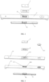
- the battery cover plate includes an electrode post plate 1, a hot-melt adhesive film 2, a cover plate assembly 3, and a busbar 4.
- the cover plate assembly 3 defines a first through hole 31.
- the electrode post plate 1 and the busbar 4 are located on two sides of the first through hole 31 on the cover plate assembly 3.
- the busbar 4 is provided with a boss 41.
- the boss 41 is embedded into the first through hole 31, and an end of the boss 41 is connected with the electrode post plate 1.
- the hot-melt adhesive film 2 includes an annular sheet 21 and a sealing gasket cylinder 22.
- a second through hole 23 is defined in the annular sheet 21 at a position corresponding to the first through hole 31.
- the sealing gasket cylinder 22 is connected with the second through hole 23 of the annular sheet 21 and extends along a direction perpendicular to a plane where the annular sheet 21 is located.
- the annular sheet 21 is thermally fused between the electrode post plate 1 and the cover plate assembly 3, and the gasket cylinder body 22 is sleeved between an outer wall of the boss 41 and an inner wall of the first through hole 31.
- the hot-melt adhesive film is selected from the group consisting of a PP adhesive film, a PE adhesive film, a polyimide adhesive film and an epoxy resin adhesive film.
- the hot-melt adhesive film 2 is a PP adhesive film, which has the characteristics of insulation and thermal-fixing.
- a thickness of the hot-melt adhesive film is not specially limited. In some embodiments, the thickness of the hot-melt adhesive film is from 10 ⁇ m to 500 ⁇ m. When the thickness of the hot-melt adhesive film is within the above range, on the one hand, the hot-melt adhesive film is beneficial to ensure the sealing connection effect, on the other hand, the adverse impact on an overall thickness of the battery cover plate caused by the excessive thickness of the hot-melt adhesive film can be avoided.
- the hot-melt adhesive film 2 is covered on the first through hole 31, and the electrode post plate 1 and the hot-melt adhesive film 2 together are placed on the first through hole 31; under the action of thermal pressing, the electrode post plate 1 and the cover plate assembly 3 are thermally fused together through the annular sheet 21 of the hot-melt adhesive film 2; at the same time, the sealing gasket cylinder 22 of the hot-melt adhesive film 2 can further seal a part of the boss 41 by thermal fusion, which provides a better sealing effect at the first through hole 31 of the electrode post plate 1 and fixes the electrode post plate 1 in a more reliable way.
- the sealing effect can be provided through the sealing gasket cylinder 22 without using a traditional rubber ring made of polyfluoroalkoxy, the battery cover plate is environmentally friendly. Furthermore, the hot-melt adhesive film 2 has a small thickness, which can avoid the space occupation of the battery cover plate and reduce the overall thickness of the battery cover plate at the position of the electrode post plate 1, which is beneficial to reduce an overall height of the battery and improve a volume energy density of the battery.
- the cover plate assembly 3 includes a plastic plate 33 and a metal cover plate 32 stacked on the plastic plate 33.
- a third through hole 321 is defined in the metal cover plate 32
- a fourth through hole 331 is defined in the plastic plate 33 at a position corresponding to the third through hole 321.
- the third through hole 321 and the fourth through hole 331 are communicated with each other to form the first through hole 31.
- the boss 41 passes through the third through hole 321 and the fourth through hole 331 in turn to abut a surface of the electrode post plate 1.
- the plastic plate 33 is arranged below the metal cover plate 32 to separate a battery cell from the metal cover plate 32. Since the metal cover plate 32 is made of metal, the plastic plate 33 can insulate the metal cover plate 32 from the battery cell to avoid the electrical connection between the metal cover plate 32 and the battery cell.
- the material of the metal cover plate 32 may be selected from the group consisting of aluminum, aluminum alloy, magnesium, magnesium alloy, iron iron alloy, nickel, nickel alloy, copper, and copper alloy, as required.
- the metal cover plate 32 can be replaced by a cover plate made of corrosion resistant non-metallic materials.
- the sealing gasket cylinder 22 of the hot-melt adhesive film 2 can seal the part of the boss 41 by thermal fusion, so as to fix the electrode post plate 1 by forming a better sealing effect in the third through hole 321 and the fourth through hole 331 where the the electrode post plate 1 is mounted.
- the plastic plate 33 is provided with an annular protrusion 332 arranged along a peripheral of the fourth through hole 331 and facing towards the metal cover plate 32.
- the boss 41 is embedded in the annular protrusion 332, and the annular protrusion 332 is embedded in the third through hole 321.
- the sealing gasket cylinder 22 is connected between an outer wall of the annular projection 332 and an inner wall of the third through hole 321 by thermal fusion.
- the third through hole 321 is a rectangular hole, that is, the protrusion arranged along the peripheral of the third through hole 321 forms a rectangular frame.
- the boss 41 is embedded in the third through hole 321 and is located inside the protrusion; correspondingly, the first through hole 31 and the second through hole 23 are rectangular holes.
- the third through hole 321 is a circular hole, that is, the protrusion arranged along the peripheral of the third through hole 321 forms a circular frame.
- the boss 41 is embedded in the third through hole 321 and is located inside the protrusion; correspondingly, the first through hole 31 and the second through hole 23 are circular holes.
- boss 41, the third through hole 321, the protrusion, the first through hole 31, and the second through hole 23 can also be of the same shape and can be used together.
- the cover plate assembly 3 is provided with a liquid injection port 322 and/or an explosion-proof valve 323.
- the liquid injection port 322 is used to inject electrolyte into the battery, and the electrolyte enters an inner cavity of the housing of the battery through the liquid injection port 322.
- the liquid injection port 322 is enclosed by welding the cover plate or setting an openable cover plate after the liquid injection.
- the explosion-proof valve 323 is provided with an annular groove to form a weak structure on the explosion-proof valve 323.
- the battery may produce a large amount of gas which forms a high pressure inside the battery.
- the explosion-proof valve 323 may be fractured at the annular groove to form an opening through which the gas inside the battery can be released, thus, a high pressure explosion of the battery can be finally avoided.
- the liquid injection port 322 and the explosion-proof valve 323 can be separately arranged on different cover plate assemblies 3; or, the liquid injection port 322 and the explosion-proof valve 323 can be arranged on the same cover plate assembly 3.
- the explosion-proof valve 323 is arranged on the metal cover plate 32, a groove 333 is formed in a middle part of the plastic plate 33, an opening of the groove 333 is enclosed by the metal cover plate 32, and the explosion-proof valve 323 is located in the opening of the groove 333.
- a plurality of ventilation liquid holes 334 are defined in a bottom of the groove 333.
- the groove 333 is connected to a surface of the battery cell to avoid the movement of the cell.
- the ventilation liquid holes 334 are located in the bottom of the groove 333.
- the groove 333 is capable of storing a certain amount of electrolyte, which improves an overall electrolyte retention amount of the battery. In the battery cycle process, the electrolyte stored in the groove 333 can be used to increse the cycle times of the electrolyte and thus to prolong the service life of the battery.
- the boss 41 is integrally formed by stretching the busbar 4 towards the electrode post plate 1.
- the boss 41 is integrally formed by stretching the busbar 4 towards the electrode post plate 1, such that the boss 41 is embedded into the fourth through hole 331 of the plastic plate 33 to assembly and fix the busbar 4 and the boss 41.
- the busbar 4 may be made of aluminum, copper, nickel, iron, titanium, silver or zirconium.
- the busbar 4 connected with a positive electrode of the battery cell is made of aluminum
- the busbar 4 connected with a negative electrode of the battery cell is made of copper.
- Aluminum or copper has an excellent conductivity.
- a single battery cover plate is provided with a single electrode post plate 1, a single hot-melt adhesive film 2, and a single busbar 4.
- a single battery is provided with two battery cover plate assemblies 3, and the two battery cover plate assemblies 3 are arranged at two ends of the housing of the battery.
- Two electrode post plates 1 are respectively arranged on the two cover plate assemblies 3 as a positive electrode and a negative electrode.
- the busbar 4 is rectangular, the boss 41 is located on a middle part of the busbar 4, the fourth through hole 331 is defined in a middle part of the plastic plate 33, and the third through hole 321 is defined in a middle part of the metal cover plate 32.
- two or more electrode post plates 1, two or more hot-melt adhesive films 2 and two or more busbars 4 can be arranged on a single battery cover plate, and the two or more electrode post plates 1, two or more hot-melt adhesive films 2 and two or more busbars 4 respectively correspond to each other.
- two or more electrode post plates 1, two or more hot-melt adhesive films 2 and two or more busbars 4 are arranged on a single battery cover plate, and the two or more electrode post plates 1, the two or more hot-melt adhesive films 2 and the two or more busbars 4 respectively correspond to each other.
- the housing of the battery is a semi-enclosed housing with one end thereof being opened, and the cover plate assembly 3 encloses the opened end of the housing.
- Two electrode post plates 1 are respectively arranged on two sides of the cover plate assembly 3 as a positive electrode and a negative electrode.
- the busbar 4 includes a bottom plate and the boss 41; the bottom plate is rectangular, a rectangular notch is formed in one side of the bottom plate, and an inclined cut-out is formed in another side of the bottom plate which is not adjacent to the side in which the notch is formed.
- the boss 41 is embedded in the fourth through hole 331 corresponding to the plastic plate 33.
- the third through hole 321 is located on left and right sides of the metal cover plate 32.
- the fourth through hole 331 is located on left and right sides of the plastic plate 33.
- a battery having the battery cover plate in any of the embodiments mentioned above is provided.
- the housing of the battery is a semi-enclosed housing with one end thereof being opened, and the cover plate assembly encloses the opened end of the housing.
- the housing of the battery is a cylindrical housing with both ends thereof being opened.
- the number of the battery cover plates is two, and the two battery cover plates respectively enclose two ends of the housing.
- the housing of the battery can be a square housing, a cylindrical housing, a prismatic housing, or any other irregular housing.
Landscapes
- Chemical & Material Sciences (AREA)
- Chemical Kinetics & Catalysis (AREA)
- Electrochemistry (AREA)
- General Chemical & Material Sciences (AREA)
- Sealing Battery Cases Or Jackets (AREA)
- Connection Of Batteries Or Terminals (AREA)
- Gas Exhaust Devices For Batteries (AREA)
- Fuses (AREA)
- Filling, Topping-Up Batteries (AREA)
Applications Claiming Priority (1)
| Application Number | Priority Date | Filing Date | Title |
|---|---|---|---|
| CN202320530173.9U CN219677389U (zh) | 2023-03-17 | 2023-03-17 | 一种电池盖板及其电池 |
Publications (2)
| Publication Number | Publication Date |
|---|---|
| EP4432431A2 true EP4432431A2 (de) | 2024-09-18 |
| EP4432431A3 EP4432431A3 (de) | 2024-12-25 |
Family
ID=87517324
Family Applications (1)
| Application Number | Title | Priority Date | Filing Date |
|---|---|---|---|
| EP23188096.4A Pending EP4432431A3 (de) | 2023-03-17 | 2023-07-27 | Batterieabdeckplatte und batterie damit |
Country Status (5)
| Country | Link |
|---|---|
| US (1) | US20240313308A1 (de) |
| EP (1) | EP4432431A3 (de) |
| JP (1) | JP2024132788A (de) |
| KR (1) | KR20240140754A (de) |
| CN (1) | CN219677389U (de) |
Families Citing this family (2)
| Publication number | Priority date | Publication date | Assignee | Title |
|---|---|---|---|---|
| EP4597695A3 (de) * | 2024-01-30 | 2025-10-15 | Huizhou Eve Power Co., Ltd | Batterieabdeckung, batterie, batteriepack und elektrische vorrichtung |
| CN222146400U (zh) * | 2024-03-25 | 2024-12-10 | 比亚迪股份有限公司 | 端盖组件、电池装置和用电设备 |
Family Cites Families (9)
| Publication number | Priority date | Publication date | Assignee | Title |
|---|---|---|---|---|
| JP5734096B2 (ja) * | 2011-05-30 | 2015-06-10 | 日立オートモティブシステムズ株式会社 | 二次電池 |
| JP2014086312A (ja) * | 2012-10-24 | 2014-05-12 | Fts:Kk | 密閉型電池 |
| US11245163B2 (en) * | 2016-08-01 | 2022-02-08 | Cps Technology Holdings Llc | Overcharge protection systems for prismatic lithium ion battery cells with biased packaging |
| JP2018097978A (ja) * | 2016-12-09 | 2018-06-21 | リチウム エナジー アンド パワー ゲゼルシャフト ミット ベシュレンクテル ハフッング ウント コンパニー コマンディトゲゼルシャフトLithium Energy and Power GmbH & Co. KG | 蓄電素子 |
| CN110854308A (zh) * | 2019-12-24 | 2020-02-28 | 瑞浦能源有限公司 | 一种锂离子电池顶盖及锂离子电池 |
| JP7446202B2 (ja) * | 2020-11-16 | 2024-03-08 | プライムプラネットエナジー&ソリューションズ株式会社 | 電池および電池の製造方法 |
| CN113471582A (zh) * | 2021-06-16 | 2021-10-01 | 西安宇动新能源电池有限公司 | 一种顶盖组件、基于该顶盖组件的锂离子电池 |
| CN113629329B (zh) * | 2021-09-09 | 2024-11-29 | 江苏正力新能电池技术股份有限公司 | 一种复合极柱、顶盖和电池 |
| CN216311920U (zh) * | 2021-09-09 | 2022-04-15 | 江苏正力新能电池技术有限公司 | 一种复合极柱、顶盖和电池 |
-
2023
- 2023-03-17 CN CN202320530173.9U patent/CN219677389U/zh active Active
- 2023-07-21 US US18/356,434 patent/US20240313308A1/en active Pending
- 2023-07-24 KR KR1020230096390A patent/KR20240140754A/ko not_active Ceased
- 2023-07-25 JP JP2023121146A patent/JP2024132788A/ja active Pending
- 2023-07-27 EP EP23188096.4A patent/EP4432431A3/de active Pending
Also Published As
| Publication number | Publication date |
|---|---|
| EP4432431A3 (de) | 2024-12-25 |
| KR20240140754A (ko) | 2024-09-24 |
| CN219677389U (zh) | 2023-09-12 |
| US20240313308A1 (en) | 2024-09-19 |
| JP2024132788A (ja) | 2024-10-01 |
Similar Documents
| Publication | Publication Date | Title |
|---|---|---|
| EP4432431A2 (de) | Batterieabdeckplatte und batterie damit | |
| CN100474656C (zh) | 电池 | |
| CN214203812U (zh) | 电池单体、电池以及用电装置 | |
| JP2022047459A (ja) | ボタン型電池及びその製造方法 | |
| JP7614225B2 (ja) | 電池および電力使用装置 | |
| US20250286177A1 (en) | Secondary battery top cover and secondary battery | |
| CN201904410U (zh) | 快速散热锂离子二次电池 | |
| CN222463111U (zh) | 一种电池单体、电池及用电装置 | |
| CN210467900U (zh) | 电池单体、电池模块、电池组及装置 | |
| CN117254174B (zh) | 电池及其盖板 | |
| CN209232828U (zh) | 铝壳锂离子电池及其壳体及其顶盖 | |
| CN221447421U (zh) | 一种极柱组件、封盖总成及电池单体 | |
| CN219677388U (zh) | 一种电池盖板组件及其电池 | |
| CN222953332U (zh) | 电池装置及用电装置 | |
| CN222813904U (zh) | 电池、电池模块和用电设备 | |
| CN220138634U (zh) | 一种单体电池 | |
| WO2024077491A1 (zh) | 壳组件、电池单体、电池及用电装置 | |
| CN223598979U (zh) | 电池单体、电池装置和用电装置 | |
| CN220065861U (zh) | 一种电池盖板及其电池 | |
| CN224153454U (zh) | 电池单体、电池装置、用电设备及储能装置 | |
| CN223757575U (zh) | 一种电池及用电装置 | |
| CN222394914U (zh) | 一种电池单体、电池及用电装置 | |
| CN223871472U (zh) | 锂离子电池 | |
| CN219658832U (zh) | 一种动力电池顶盖 | |
| CN223079291U (zh) | 具有防爆阀的壳体及动力电池 |
Legal Events
| Date | Code | Title | Description |
|---|---|---|---|
| PUAI | Public reference made under article 153(3) epc to a published international application that has entered the european phase |
Free format text: ORIGINAL CODE: 0009012 |
|
| STAA | Information on the status of an ep patent application or granted ep patent |
Free format text: STATUS: REQUEST FOR EXAMINATION WAS MADE |
|
| 17P | Request for examination filed |
Effective date: 20230727 |
|
| AK | Designated contracting states |
Kind code of ref document: A2 Designated state(s): AL AT BE BG CH CY CZ DE DK EE ES FI FR GB GR HR HU IE IS IT LI LT LU LV MC ME MK MT NL NO PL PT RO RS SE SI SK SM TR |
|
| PUAL | Search report despatched |
Free format text: ORIGINAL CODE: 0009013 |
|
| STAA | Information on the status of an ep patent application or granted ep patent |
Free format text: STATUS: EXAMINATION IS IN PROGRESS |
|
| AK | Designated contracting states |
Kind code of ref document: A3 Designated state(s): AL AT BE BG CH CY CZ DE DK EE ES FI FR GB GR HR HU IE IS IT LI LT LU LV MC ME MK MT NL NO PL PT RO RS SE SI SK SM TR |
|
| RIC1 | Information provided on ipc code assigned before grant |
Ipc: H01M 50/193 20210101ALI20241119BHEP Ipc: H01M 50/186 20210101ALI20241119BHEP Ipc: H01M 50/627 20210101ALI20241119BHEP Ipc: H01M 50/553 20210101ALI20241119BHEP Ipc: H01M 50/342 20210101ALI20241119BHEP Ipc: H01M 50/188 20210101ALI20241119BHEP Ipc: H01M 50/184 20210101ALI20241119BHEP Ipc: H01M 50/176 20210101ALI20241119BHEP Ipc: H01M 50/15 20210101AFI20241119BHEP |
|
| 17Q | First examination report despatched |
Effective date: 20241206 |