EP4425035A1 - Module de surveillance de porte de protection - Google Patents
Module de surveillance de porte de protection Download PDFInfo
- Publication number
- EP4425035A1 EP4425035A1 EP24159871.3A EP24159871A EP4425035A1 EP 4425035 A1 EP4425035 A1 EP 4425035A1 EP 24159871 A EP24159871 A EP 24159871A EP 4425035 A1 EP4425035 A1 EP 4425035A1
- Authority
- EP
- European Patent Office
- Prior art keywords
- actuator
- bolt
- protective door
- monitoring module
- bearing body
- Prior art date
- Legal status (The legal status is an assumption and is not a legal conclusion. Google has not performed a legal analysis and makes no representation as to the accuracy of the status listed.)
- Pending
Links
Images



Classifications
-
- F—MECHANICAL ENGINEERING; LIGHTING; HEATING; WEAPONS; BLASTING
- F16—ENGINEERING ELEMENTS AND UNITS; GENERAL MEASURES FOR PRODUCING AND MAINTAINING EFFECTIVE FUNCTIONING OF MACHINES OR INSTALLATIONS; THERMAL INSULATION IN GENERAL
- F16P—SAFETY DEVICES IN GENERAL; SAFETY DEVICES FOR PRESSES
- F16P3/00—Safety devices acting in conjunction with the control or operation of a machine; Control arrangements requiring the simultaneous use of two or more parts of the body
- F16P3/08—Safety devices acting in conjunction with the control or operation of a machine; Control arrangements requiring the simultaneous use of two or more parts of the body in connection with the locking of doors, covers, guards, or like members giving access to moving machine parts
-
- E—FIXED CONSTRUCTIONS
- E05—LOCKS; KEYS; WINDOW OR DOOR FITTINGS; SAFES
- E05B—LOCKS; ACCESSORIES THEREFOR; HANDCUFFS
- E05B47/00—Operating or controlling locks or other fastening devices by electric or magnetic means
- E05B47/0046—Electric or magnetic means in the striker or on the frame; Operating or controlling the striker plate
-
- G—PHYSICS
- G05—CONTROLLING; REGULATING
- G05B—CONTROL OR REGULATING SYSTEMS IN GENERAL; FUNCTIONAL ELEMENTS OF SUCH SYSTEMS; MONITORING OR TESTING ARRANGEMENTS FOR SUCH SYSTEMS OR ELEMENTS
- G05B19/00—Program-control systems
- G05B19/02—Program-control systems electric
- G05B19/04—Program control other than numerical control, i.e. in sequence controllers or logic controllers
-
- E—FIXED CONSTRUCTIONS
- E05—LOCKS; KEYS; WINDOW OR DOOR FITTINGS; SAFES
- E05C—BOLTS OR FASTENING DEVICES FOR WINGS, SPECIALLY FOR DOORS OR WINDOWS
- E05C1/00—Fastening devices with bolts moving rectilinearly
- E05C1/08—Fastening devices with bolts moving rectilinearly with latching action
-
- E—FIXED CONSTRUCTIONS
- E05—LOCKS; KEYS; WINDOW OR DOOR FITTINGS; SAFES
- E05B—LOCKS; ACCESSORIES THEREFOR; HANDCUFFS
- E05B47/00—Operating or controlling locks or other fastening devices by electric or magnetic means
- E05B2047/0048—Circuits, feeding, monitoring
- E05B2047/0067—Monitoring
- E05B2047/0068—Door closed
-
- E—FIXED CONSTRUCTIONS
- E06—DOORS, WINDOWS, SHUTTERS, OR ROLLER BLINDS IN GENERAL; LADDERS
- E06B—FIXED OR MOVABLE CLOSURES FOR OPENINGS IN BUILDINGS, VEHICLES, FENCES OR LIKE ENCLOSURES IN GENERAL, e.g. DOORS, WINDOWS, BLINDS, GATES
- E06B9/00—Screening or protective devices for wall or similar openings, with or without operating or securing mechanisms; Closures of similar construction
- E06B2009/002—Safety guards or gates
Definitions
- the present invention relates to a protective door monitoring module for monitoring a state of a protective door.
- the present invention relates to a protective door monitoring system with a protective door as access to a safety area, a protective door monitoring module of the above-mentioned type, an actuator and a control unit which is designed to read out a protective door signal and to control a machine or system located in the safety area depending on the protective door signal.
- Safety door monitoring modules of the type mentioned above are often also referred to as safety switches. Examples of safety door monitoring modules or safety switches of the type mentioned above are from the EN 10 2005 057 108 A1 , the DE 103 05 704 B3 , the EN 10 2008 060 004 A1 and from the EN 10 2020 120 817 A1 known.
- Protective door monitoring modules of this type are used on protective doors, protective flaps and the like.
- the terms “protective door monitoring module” and “protective door” are used here, the protective door monitoring module according to the invention can be used on any type of separating protective device.
- the term “protective door” is to be interpreted broadly in the present sense. Instead of the general term “separating protective device”, the term “protective door” is therefore used exclusively in the following, without this being intended to result in a restriction of the protection area.
- Safety doors typically serve as access to a safety area in which an automated machine or system is located.
- the machine can be, for example, a robot, a machine tool with a fast-rotating spindle, a transport or conveyor system, a press or another machine or system whose operation poses a danger to people who are in the safety area mentioned or in the working area of the machine.
- the safety door monitoring module can serve as a signaling device with the help of which a control unit can detect the closed state of the safety door.
- the control unit is set up to read the safety door signal generated by the safety door monitoring module and to control the machine depending on the safety door signal. For example, the machine can only be operated if the safety door signal is present.
- control unit is designed to only allow the machine or system to operate when it receives the safety door signal from the safety door monitoring module, i.e. when the safety door is closed. However, if the safety door is opened during operation (if possible), the control unit must bring the machine or system into a safe state by, for example, switching off the power supply to the machine or system.
- guard locking There are a large number of machines and systems that pose a risk for a certain period of time even after they have been switched off, for example because the machine or system is still running. For such applications, safety door monitoring modules are required that prevent the safety door from opening until the machine or system has reached a safe state. This function is known as guard locking.
- safety door monitoring modules of this type have a so-called actuator and an actuator holder that acts as a counterpart to it.
- the actuator holder is part of a base unit, which typically houses other electronic components and from which the connecting cables that connect the safety door monitoring module to the control unit usually originate.
- the base unit with the actuator holder is preferably arranged on a stationary part of the safety door (e.g. on a door frame), while the actuator is preferably arranged on a moving part of the safety door (e.g. on a moving door leaf).
- the actuator When the safety door is closed, the actuator reaches into the actuator holder, which is detected using one or more sensors. In a safety door monitoring module with guard locking, the actuator is also blocked or locked in the actuator holder to prevent it from being pulled back.
- the so-called guard locking has a locking device for locking the actuator in the actuator holder.
- the safety door monitoring module therefore fulfils two functions, namely a detection function, which is used to detect the closed position of the safety door, and a locking function, which prevents the safety door from opening as long as the actuator is locked in the actuator holder.
- the actuator can be released, for example, via an electromotive actuator that is operated by the control unit as soon as the monitored machine or system has reached its safe state.
- a safety door monitoring module of this type is sold by the applicant under the name PSENmlock.
- This safety door monitoring module can be used in a variety of ways.
- the actuator of the safety door monitoring module can essentially be rod- or pin-shaped and the actuator holder acting as a counterpart can have a continuous groove, a U-shaped opening or a blind or through hole into which the rod- or pin-shaped actuator engages.
- the protective door monitoring module for monitoring a state of a protective door has an actuator receptacle for receiving an actuator and is designed to generate a protective door signal when the actuator is inserted into the actuator receptacle, wherein the actuator receptacle has a locking device which is designed to hold the actuator in the actuator receptacle in an activated state, wherein the locking device has a bolt with a bearing body receptacle and a bearing body which is rotatably mounted in the bearing body receptacle and which is arranged on a free end of the bolt which is designed to engage in the actuator in the activated state.
- the locking device according to the invention therefore has in particular a bearing body which is rotatably mounted in the bolt and is arranged such that the bearing body can be in contact with the actuator.
- the bearing body mounted in the bolt can roll on the actuator.
- the bearing body can be in contact with the actuator when it is inserted into the actuator holder in order to simplify the insertion of the actuator into the actuator holder and/or to reduce friction and/or wear between the locking device and the actuator. If the bearing body rolls on the actuator when the actuator is inserted into the actuator holder instead of sliding on the actuator, the frictional contact is predominantly characterized by rolling friction instead of sliding friction. This allows the friction in the frictional contact to be reduced. The same applies to the opening process of the protective door, during which the actuator is guided out of the actuator holder.
- the present invention also advantageously enables a freer and therefore simpler design of the bolt.
- the shape of the bolt can be designed more independently of the actuator.
- the bearing body can be machined independently of the rest of the bolt, for example with regard to surface quality, in order to improve the properties of the frictional contact. This can have a simplifying effect on the manufacture of the locking device and/or the actuator.
- the present invention makes it possible to replace the bearing body independently of the rest of the bolt. Even if the locking device according to the present invention is associated with reduced wear compared to conventional locking devices, the bearing body can still wear out with continued use. In this case, the present invention makes it possible to specifically replace only the bearing body and continue to use the remaining parts of the bolt. The components of the locking device can therefore be used sustainably.
- the materials of the friction contact partners are usually matched to one another.
- the present invention It also allows the locking device to be made of different materials. This allows the materials of the friction contact partners to be better coordinated with one another.
- the bearing body can have a material that is different from the material of the bolt.
- the properties of the frictional contact can be determined by a selected material combination of the bearing body and actuator, while at the same time the selection of the material of the bolt can be made more independent of the material of the actuator.
- the bolt has a loss prevention device which is designed to hold the rotatably mounted bearing body captively on the bolt.
- the bearing body is permanently held in the desired position and/or alignment in the bolt. This can improve the reliability of the protective door monitoring module.
- the loss prevention device is formed by means of a cross-sectional narrowing of the bearing body receptacle.
- the bearing body holder is narrowed in order to hold the bearing body in the desired position and/or alignment in the bolt.
- the cross-sectional constriction can act as a locking element for the bearing body. This enables simple and cost-effective production of the locking device.
- the diameter of the cross-sectional constriction is smaller than the diameter of the bearing body.
- the bearing body is a ball.
- a ball has the advantage that, due to its symmetry, it can be used as a multidirectional bearing body. This means that the actuator can be inserted into the actuator from any direction, while the ball as a bearing body takes on the aforementioned function of reducing friction and wear.
- the bearing body can also have another suitable shape, such as that of a circular cylinder, which is particularly suitable for rotating or rolling on the actuator.
- the bearing body receptacle has a first portion which is conical, spherical cap-shaped or cylindrical, and a second portion which is cylindrical.
- the first section can in particular be at least partially in contact with the bearing body and/or function as a receptacle for a bearing insert.
- the second section can in particular be at least partially in contact with the bearing body and/or function as a casing or housing (in particular to prevent the ingress of foreign bodies).
- more than half of the bearing body is arranged within the bearing body receptacle.
- the bolt is preloaded by means of a spring device.
- the spring device is designed to activate the locking device so that the locking device holds the actuator in the actuator holder.
- the spring device acts on a side of the bolt opposite the free end and can press the bearing body into engagement with the actuator. When the bolt is inserted and removed from the actuator, the bolt can give way against the spring force.
- the bolt has a base body and a bearing shell inserted therein, which forms at least part of the bearing body receptacle.
- the bolt is therefore constructed in at least two or three parts.
- the bearing body is arranged rotatably in the (inserted) bearing shell.
- the bearing shell can be designed to accommodate the bearing body in such a way that the bearing body can roll on the bearing shell.
- reduced requirements can thus be placed on the design of the bolt and the design of the bearing body holder, so that the manufacture of the bolt can be simplified.
- the frictional contact can be lubricated.
- the bearing body receptacle is conical on a side opposite the bearing body.
- the base body of the bolt has a first material and the bearing shell has a second material that is different from the first material.
- This design advantageously allows the bearing shell used to have a material that is different from the material of the bolt. This means that the properties of the frictional contact between the bearing body and the bearing shell can be specifically adjusted independently of the material of the bolt (particularly with regard to reducing friction and wear).
- the bolt has a sleeve which is fastened to a base body of the bolt and forms at least part of the bearing body receptacle.
- the bearing body holder is designed in at least two parts, with at least one part of the bearing body holder being formed by the base body of the bolt and the sleeve attached to it.
- reduced manufacturing requirements can therefore be placed on the base body of the bolt, enabling the bolt to be manufactured inexpensively and easily.
- the sleeve forms at least part of the loss prevention device.
- the sleeve forms part of the cross-sectional constriction of the bearing body receptacle.
- the sleeve can thus function as a locking element for the bearing body.
- the base body of the bolt with regard to the manufacture of the bearing body holder, so that the The manufacture of the bolt can be simplified.
- the bearing body can be pre-assembled more easily, so that the sleeve can serve as a loss protection for the assembly process, for example.
- the sleeve can be attached to the base body of the bolt in a detachable or non-detachable manner.
- the sleeve can be attached to the base body in a force-fitting or form-fitting manner, for example by means of a thread, a rivet or a pin.
- the sleeve can also or additionally be connected to the base body in a material-fitting manner, in particular glued, soldered and/or welded.
- the sleeve can also be shrunk onto the base body, for example.
- a sleeve that is detachably attached to the base body can have the advantage that the bearing body can be easily replaced - for example after a certain number of closing and opening operations of the actuator and/or a specified wear limit has been exceeded.
- the bolt has a plurality of bearing balls which are arranged in the bearing body receptacle.
- the bearing body and the bearing balls can be designed to be in contact with one another and to roll on one another.
- the bearing balls can advantageously have a material that is different from the material of the bolt. This makes it easier to specifically adjust the properties of the frictional contact between the bearing body and the bearing balls independently of the bolt (in particular with regard to reducing friction and wear).
- the bearing balls each have a diameter that is smaller than the diameter of the bearing body. More preferably, the bearing balls each have the same diameter.
- the actuator has at least a part (in particular in the contact area with the locking device in the activated state of the locking device) as Material is a chromium-nickel-molybdenum stainless steel alloy and/or the bearing body is a rolling bearing steel and/or the bolt is a free-cutting or case-hardening steel.
- a further aspect of the present invention relates to a protective door monitoring system which has a protective door of the aforementioned type (with a protective door monitoring module according to the invention), an actuator and a control unit.
- the first part of the safety door on which the base unit is arranged is a stationary part of the safety door (e.g. a door frame or a door casing).
- the second part of the safety door on which the actuator is arranged is preferably a movable door element (e.g. a door leaf).
- the arrangement of the base unit on the stationary part of the safety door has the advantage that the part of the safety door monitoring module mounted on the movable part of the safety door does not need to be supplied with power, since typically only the base unit of the safety door monitoring module needs to be supplied with power.
- the actuator preferably has a receptacle which is designed to accommodate the locking device in the activated state.
- the receptacle of the actuator is further preferably designed to be in contact with the bearing body.
- the receptacle of the actuator therefore preferably has a counter-shape corresponding to the shape of the bearing body, in particular a conical, spherical cap-shaped or cylindrical counter-shape.
- Fig.1 shows a schematic view of an embodiment of a protective door monitoring system according to the invention.
- the protective door monitoring system is designated in its entirety with the reference number 10.
- the protective door monitoring system 10 here includes a robot 12 whose working area is secured by means of a protective door 14.
- a protective door monitoring module 16 according to the present invention is arranged on the protective door 14.
- the safety door monitoring module 16 comprises a door part 17, which is arranged on the movable door element (door leaf) of the safety door 14, and a frame part 18, which is arranged on a stationary second part 20 of the safety door 14.
- the stationary second part 20 of the safety door 14 is a door frame or a door casing. In other exemplary embodiments, this second stationary part 20 of the safety door 14 can also be a second door leaf of a two-part safety door.
- the frame part 18 of the safety door monitoring module 16 is connected to a safety relay 26 via two cables 22, 24.
- the safety relay 26 is, for example, a safety relay from the PNOZ ⁇ ® > series, which is manufactured by the applicant of the This is a multi-channel redundant safety switching device that is designed to evaluate the output signals from signaling devices, such as the safety door monitoring module 16, and to switch off an electrical consumer as a function of this. In this case, the electrical consumer is the robot 12. Accordingly, the safety switching device 26 controls two contactors 28, 30, whose working contacts are arranged in the connection between a power supply 32 and the robot 12.
- the protective door monitoring module 16 could also be connected to a programmable safety controller, as sold by the applicant of the present invention under the name PSS ⁇ ® >.
- the safety switching device 26 is therefore referred to generally below as the control unit 26 of the protective door monitoring system 10, without being limited to a specific design of this control unit.
- Several exemplary embodiments of the protective door monitoring module 16 according to the invention are described below. Identical or equivalent components are designated with the same reference numerals.
- Fig. 2 shows a perspective view of the safety door monitoring module 16 with a base unit 34 and an actuator 36 that interacts with the base unit 34.
- the base unit 34 preferably comprises one or more sensors and/or other electronic components and is therefore preferably connected to a power supply. Furthermore, the base unit 34 is preferably connected to the control unit 26 via multi-channel redundant lines, such as the lines 22, 24 here.
- the base unit 34 preferably forms the previously mentioned frame part 18 of the safety door monitoring module 16.
- the base unit 34 as the door part 17 of the protective door monitoring module 16
- the usually fixed wiring with the control unit 26 and the power supply would have to be routed to the moving part of the protective door 14, which is generally more complicated than routing the cables 22, 24 and the power supply to the static part 20 of the protective door 14.
- the actuator 36 acts as a counterpart to the base unit 34 and serves to actuate the base unit 34.
- the base unit 34 has a corresponding actuator receptacle 38 into which the actuator 36 can be inserted.
- the base unit 34 is to detect whether the actuator 36 is inserted into the actuator receptacle 38 or not.
- the actuator 36 preferably has an RFID chip that can be read by a detector arranged in the actuator receptacle 38.
- the base unit 34 is designed to generate a safety door signal when the actuator 36 is inserted into the actuator receptacle 38.
- This safety door signal is preferably generated as an electrical signal. This can be a digital, pulsed, coded and/or other (preferably electrical) signal.
- the safety door monitoring system 10 can clearly determine at any time whether the safety door 14 is closed or not.
- the robot 12 can be controlled depending on this in such a way that it can only be operated when the safety door 14 is closed.
- Fig.2 , 3A and 3B show the actuator element 40 inserted in the closed state of the protective door 14 in the actuator holder 38.
- the actuator 36 has a substantially rod/pin-shaped actuator element 40, which can be inserted into the actuator receptacle 38.
- the actuator element 40 On its front side inserted into the actuator receptacle 38, the actuator element 40 has a through hole 42 designed as a catch bore (see Fig. 3B ) into which a locking device 44 engages in order to hold the actuator 36 in the actuator receptacle 38 in the activated state of the locking function.
- the basic device 34 also has one or more optical control displays 46, which indicate a state of the safety door monitoring module 16. Furthermore, the basic device 34 has an operating device 48, by means of which a user can change a state of the safety door monitoring module 16. For example, the operating device 48 is designed to control the locking function of the Safety door monitoring module 16 as an "emergency release" by unlocking the locking device 44.
- the locking device 44 has a bolt 50, a spring device 52 and a locking device 53.
- the bolt 50 has a bearing body 54 rotatably mounted thereon and is preloaded by means of the spring device 52 and designed to engage in the through hole 42 of the actuator 36. Due to the spring preload, the bolt 50 deviates downwards against the spring force generated by the spring device 52 when the actuator 36 is inserted and removed from the actuator receptacle 38.
- the locking device 53 is designed to lock the bolt 50 in the activated state of the locking device 44, whereby the actuator 36 is held in the actuator receptacle 38.
- the bolt 50 can be locked automatically as a result of a signal (e.g. from the control unit 26 or the safety door monitoring module 16) or manually using the operating device 48. If the safety door 14 is to be opened again, the actuator 36 must first be removed from the actuator holder 38. To do this, the locking device 53 automatically releases the bolt 50 again as a result of a corresponding signal or as a result of manual unlocking using the operating device 48.
- a signal e.g. from the control unit 26 or the safety door monitoring module 16
- the actuator 36 must first be removed from the actuator holder 38. To do this, the locking device 53 automatically releases the bolt 50 again as a result of a corresponding signal or as a result of manual unlocking using the operating device 48.
- Fig.5 shows a first embodiment of the bolt 50, which forms part of the locking device 44, in a sectional view.
- the bolt 50 has a bearing body 54 which is rotatably mounted on it and is designed here as a ball 56.
- the ball 56 is rotatably arranged in a bearing body receptacle 58 formed in the bolt 50, the bearing body receptacle 58 being formed in a base body 60 of the bolt 50. More than half of the ball volume is arranged in the bearing body receptacle 58.
- the ball 56 used as bearing body 54 is arranged at a free end 62 of the bolt 50, so that when the bolt 50 is inserted into the actuator element 40, the ball 56 is in contact with the actuator element 40 and can roll on it. Likewise When the bolt is removed from the actuator 36, the ball 56 can roll on the actuator element 40.
- the bearing body holder 58 shown has a first section 64 and a second section 66.
- the first section 64 is conical in shape, but can also be cylindrical, spherical cap-shaped, etc.
- the ball 56 can roll in this first section 64 in the bearing body receptacle 58.
- the second section 66 is cylindrical, but can also be cuboid-shaped, etc.
- the ball 56 is in the Fig.5 shown embodiment are held in position by means of the second portion 66, wherein the second portion 66 simultaneously functions as a housing.
- the bolt 50 is at least partially designed as a cylindrical body.
- a cylindrical body means a body whose cross-sectional area is constant along the longitudinal axis.
- the bolt can in particular be a circular cylinder (as for example in Fig.5 shown), but also a cuboid-shaped body or a prism, etc.
- the bolt 50 also has a loss prevention device 78 for holding the ball 56 on the bolt 50.
- the bearing body holder 58 has a cross-sectional constriction 80 on the free end 62 of the bolt 50, which functions as a locking element and thus as a loss prevention device 78 for the ball 56.
- the cross-sectional constriction 80 is smaller than the diameter of the ball 56.
- the cross-sectional constriction 80 can be manufactured, for example, by means of a stamping process.
- Fig.6 shows schematically the embossing process on the Fig.5 shown bolt 50.
- the bolt 50 is manufactured as a turned part and the bearing body holder 58 by making a hole.
- the cross section of the bearing body holder 58 is narrowed by means of a stamping die 82 and a counterholder 84.
- the arrow in Fig.6 shows the direction in which the stamping die 82 is pressed against the counterholder 84. It should be noted that the stamping process must maintain the rotatability of the mounted ball 56 or must not impair it.
- Fig.7 shows a second embodiment of the bolt 50, in which, in contrast to the one in Fig.5 shown bolt 50, the bearing body 54 is a rotatably mounted circular cylinder 68 (or “barrel”, “needle”, etc.). Just like the ball 56, the circular cylinder 68 can roll on the actuator 36. It is understood, however, that if the bearing body 54 is designed as a barrel or circular cylinder, the actuator 36 can only be inserted into the actuator receptacle 38 from one direction and not from different directions. Such a design could be used, for example, in the case of a sliding door.
- the first section 64 has a counter-shape corresponding to the circular cylinder 68, which holds the circular cylinder in position.
- the second section 66 is cuboid-shaped.
- Fig.8 and Fig.9 show two further embodiments of the bolt 50, in which a bearing shell 70 is inserted into the base body 60 of the bolt 50 and forms part of the bearing body receptacle 58
- the first section 64 of the bearing body holder 58 merges into the second section 66, or the first section 64 and the second section 66 are both cylindrical with the same diameter.
- the first section 64 is conical and the second section 66 is cylindrical.
- the conical first section 64 can be manufactured by means of a conventional bore.
- the bearing shells 70 in the Fig.8 and 9 The embodiments shown have a counter-shape corresponding to the first section 64 and the second section 66.
- the bearing shell 70 is inserted from the free end 62 into the bearing body receptacle 58 of the bolt 50.
- the bearing shell 70 and the base body 60 can be manufactured separately, which enables simpler manufacture.
- the material of the base body 60 can, for example, be a comparatively inexpensive free-cutting steel, while the material of the bearing body holder 70 can be optimized with regard to wear properties.
- Fig.10 shows another embodiment of the bolt 50.
- the bearing body holder 58 is here, similar to the one in Fig.5 shown embodiment is formed directly in the base body 60 of the bolt 50.
- a bearing shell 70 could also be provided here as before.
- a plurality of bearing balls 74 are arranged in the bearing body receptacle 58, on which the ball 56 can roll.
- the bearing balls 74 are arranged in the bearing body receptacle 58 between the ball 56 and the base body 60 of the bolt 50.
- the bearing balls 74 have a diameter that is smaller than the diameter of the ball 56. This allows the ball 56 to roll simultaneously on a large number of bearing balls 74 with a large number of contact points 76.
- the bearing balls 74 as a whole can adapt to the contour of the bearing body receptacle 58 (in particular the first section 64) and can be distributed in the bearing body receptacle 58.
- the first section 64 of the bearing body receptacle 58 is designed in the shape of a spherical cap.
- Fig. 11A shows another embodiment of the bolt 50.
- the bolt 50 here has an additional sleeve 86 on which the loss prevention device 78 for the ball 56 is formed.
- the sleeve 86 is arranged on the base body 60 of the bolt 50 and also forms part of the bearing body receptacle 58.
- the cross-sectional constriction 80 is not formed on the base body 60, but on the sleeve 86.
- the ball 56 and the bearing shell 70 are inserted into the sleeve 86.
- the sleeve 86 thus forms a housing for a part of the ball 56 and the bearing shell 70. It is understood, however, that when the bolt 50 is designed with such a sleeve 86, the bearing shell 70, which is designed here as a separate component is not necessarily provided.
- the bearing body receptacle 58 can be integrated directly into the base body 60 of the bolt 50, as is the case, for example, with the Fig.5 shown bolt 50 is the case.
- Fig. 11B and 11C show schematically the assembly of the Fig. 11A shown bolt 50.
- the ball 56 and then the bearing shell 70 are inserted into the sleeve 86 ( Fig. 11C ).
- the base body 60 of the bolt 50 is then inserted into the sleeve 86 or the sleeve 86 with the ball 56 and the bearing shell 70 is placed on the base body 60 of the bolt 50 ( Fig. 11A ).
- the stamping process shown is eliminated as a manufacturing step, so that the stamping die 82 (and the counterholder 84) are not required as a separate tool for production, which simplifies assembly.
- the sleeve 86 can be detachably or non-detachably connected to the base body 60 of the bolt 50.
- Fig. 12-15 show various embodiments.
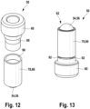
- the sleeve 86 can be screwed to the base body 60 of the bolt 50 ( Fig. 12 ) or welded or soldered ( Fig. 13 ) or by means of a pen ( Fig. 14 ) or an embossing ( Fig. 15 ) to the base body 60.
- Fig. 12 shows the base body 60 with an external thread 88 and the sleeve 86 with a corresponding internal thread 90, which is formed on a part of the inner surface of the sleeve 86.
- the base body 60 of the bolt 50 and the sleeve 86 can thus be detachably screwed together.
- the sleeve 86 can be unscrewed from the base body 60.
- Fig. 13 shows the bolt 50 with the sleeve 86, which is attached to the base body 60 by means of a plurality of weld seams 92.
- the weld seams 92 are evenly distributed over the circumference of the base body 60 or the sleeve 86.
- Fig. 14 shows the bolt 50 with the sleeve 86 and a pin 94 which is arranged in a through hole 96 of the base body 60 of the bolt 50 and the sleeve 86 and fastens the base body 60 to the sleeve 86.
- the center axes of the through hole 96 of the base body 60 and the sleeve 86 are aligned with one another and run essentially orthogonal to the longitudinal axis of the bolt 50.
- Fig. 15 shows the bolt 50 with the sleeve 86, whereby the sleeve 86 is attached to the base body 60 by means of embossings 98.
- the embossing 98 is created by the plastic pressing of a part of the sleeve 86 into the base body 60, whereby the sleeve 86 is connected to the base body 60 by means of force and form locking.
- the embossing 98 can be introduced by a punch.
- the base body 60 has two recesses 100 (or receptacles) into which a part of the sleeve 86 is pressed.
- the base body 60 of the bolt 50 can also have one or more recesses 100 for stamping, which are point-shaped, run continuously all the way around or run partially all the way around. However, the base body 60 can also have no prefabricated recesses 100, so that a part of the sleeve 86 is pressed plastically into the material of the base body 60 by means of stamping.
Landscapes
- Engineering & Computer Science (AREA)
- Mechanical Engineering (AREA)
- General Engineering & Computer Science (AREA)
- Physics & Mathematics (AREA)
- General Physics & Mathematics (AREA)
- Automation & Control Theory (AREA)
- Refuge Islands, Traffic Blockers, Or Guard Fence (AREA)
- Lock And Its Accessories (AREA)
- Power-Operated Mechanisms For Wings (AREA)
- Rolling Contact Bearings (AREA)
Applications Claiming Priority (1)
| Application Number | Priority Date | Filing Date | Title |
|---|---|---|---|
| DE102023104853.8A DE102023104853A1 (de) | 2023-02-28 | 2023-02-28 | Schutztürüberwachungsmodul |
Publications (1)
| Publication Number | Publication Date |
|---|---|
| EP4425035A1 true EP4425035A1 (fr) | 2024-09-04 |
Family
ID=90097760
Family Applications (1)
| Application Number | Title | Priority Date | Filing Date |
|---|---|---|---|
| EP24159871.3A Pending EP4425035A1 (fr) | 2023-02-28 | 2024-02-27 | Module de surveillance de porte de protection |
Country Status (5)
| Country | Link |
|---|---|
| US (1) | US20240318465A1 (fr) |
| EP (1) | EP4425035A1 (fr) |
| JP (1) | JP7696033B2 (fr) |
| CN (1) | CN118564158A (fr) |
| DE (1) | DE102023104853A1 (fr) |
Citations (7)
| Publication number | Priority date | Publication date | Assignee | Title |
|---|---|---|---|---|
| DE9013198U1 (de) * | 1990-09-18 | 1991-01-10 | K.A. Schmersal Gmbh & Co, 5600 Wuppertal | Sicherheitsschalter für Schutzabdeckungen o.dgl. |
| DE10305704B3 (de) | 2003-02-12 | 2004-06-24 | K.A. Schmersal Gmbh & Co | Sicherheitszuhaltung |
| DE102005057108A1 (de) | 2005-11-28 | 2007-05-31 | Pilz Gmbh & Co. Kg | Sicherheitsschalter zum Erzeugen eines Freigabesignals in Abhängigkeit von der Position einer beweglichen Schutztür |
| DE102008060004A1 (de) | 2008-11-25 | 2010-05-27 | Pilz Gmbh & Co. Kg | Sicherheitsschalter zum Erzeugen eines Anlagenfreigabesignals in Abhängigkeit von der Position einer beweglichen Schutztür |
| US20150040348A1 (en) * | 2013-08-06 | 2015-02-12 | Gregory Header | Door Catch |
| US20190178014A1 (en) * | 2017-12-13 | 2019-06-13 | Sick Ag | Safety locking device |
| DE102020120817A1 (de) | 2020-08-06 | 2022-02-10 | Pilz Gmbh & Co. Kg | Schutztürüberwachungsmodul |
Family Cites Families (20)
| Publication number | Priority date | Publication date | Assignee | Title |
|---|---|---|---|---|
| GB1245930A (en) * | 1967-12-22 | 1971-09-15 | Itw Ltd | Spring loaded catches |
| JPS59168470U (ja) * | 1983-04-26 | 1984-11-10 | ナショナル住宅産業株式会社 | ドアの閉成構造 |
| JPH045304Y2 (fr) * | 1987-08-10 | 1992-02-14 | ||
| JP2726912B2 (ja) * | 1990-06-06 | 1998-03-11 | 関東自動車工業株式会社 | 扉支持構造 |
| US5488207A (en) * | 1992-01-31 | 1996-01-30 | Niwa; Takashi | Key switch with a locking arrangement on a rotating element |
| DE4215187A1 (de) * | 1992-05-08 | 1993-11-11 | Schaeffler Waelzlager Kg | Schaltarretierung |
| DE4328297C1 (de) * | 1993-08-23 | 1995-02-23 | Euchner & Co | Sicherheitsschalter |
| US5541562A (en) * | 1994-10-16 | 1996-07-30 | Honeywell Inc. | Apparatus for sensing the closure of a door |
| ES2184635B1 (es) * | 2001-08-30 | 2004-09-01 | Investigacion Y Transferancia De Tecnologia, S.L. | Cerradura de seguridad y control. |
| DE10230564A1 (de) * | 2002-07-05 | 2004-01-29 | Gerhard Thiel | Kodierte Verriegelungseinrichtung mit Zuhaltung |
| GB0521847D0 (en) * | 2005-10-26 | 2005-12-07 | Pbt Ip Ltd | Low power multi-directional lock mechanism |
| DE102013014456B4 (de) * | 2013-08-30 | 2016-03-24 | Euchner Gmbh + Co. Kg | Betätiger eines Sicherheitsschalters sowie Sicherheitsschalter mit einem solchen Betätiger |
| DE102015104211A1 (de) | 2015-03-20 | 2016-09-22 | Pilz Gmbh & Co. Kg | Sicherheitsschaltgerät zum fehlersicheren Abschalten einer elektrischen Last |
| US10662676B1 (en) * | 2016-04-14 | 2020-05-26 | Apple Inc. | Concealed latch |
| DE202017100157U1 (de) | 2017-01-13 | 2017-12-07 | Otto Ganter Gmbh & Co. Kg Normteilefabrik | Kugelschnäpper |
| EP3588527B1 (fr) * | 2017-02-24 | 2021-10-06 | Idec Corporation | Commutateur de sécurité |
| JP6745568B2 (ja) * | 2018-01-11 | 2020-08-26 | Idec株式会社 | 安全スイッチ |
| JP7122851B2 (ja) * | 2018-04-13 | 2022-08-22 | 株式会社キーエンス | 安全スイッチ |
| DE102018009217A1 (de) | 2018-11-23 | 2020-05-28 | K.A. Schmersal Holding Gmbh & Co. Kg | Verriegelungseinrichtung mit Zuhaltung für Schutztüren |
| DE102021109993B3 (de) | 2021-04-20 | 2022-09-01 | Pilz Gmbh & Co. Kg | Sicherheitsschalter mit Zuhaltung |
-
2023
- 2023-02-28 DE DE102023104853.8A patent/DE102023104853A1/de active Pending
-
2024
- 2024-02-26 CN CN202410207161.1A patent/CN118564158A/zh active Pending
- 2024-02-26 JP JP2024026553A patent/JP7696033B2/ja active Active
- 2024-02-27 EP EP24159871.3A patent/EP4425035A1/fr active Pending
- 2024-02-28 US US18/590,416 patent/US20240318465A1/en active Pending
Patent Citations (7)
| Publication number | Priority date | Publication date | Assignee | Title |
|---|---|---|---|---|
| DE9013198U1 (de) * | 1990-09-18 | 1991-01-10 | K.A. Schmersal Gmbh & Co, 5600 Wuppertal | Sicherheitsschalter für Schutzabdeckungen o.dgl. |
| DE10305704B3 (de) | 2003-02-12 | 2004-06-24 | K.A. Schmersal Gmbh & Co | Sicherheitszuhaltung |
| DE102005057108A1 (de) | 2005-11-28 | 2007-05-31 | Pilz Gmbh & Co. Kg | Sicherheitsschalter zum Erzeugen eines Freigabesignals in Abhängigkeit von der Position einer beweglichen Schutztür |
| DE102008060004A1 (de) | 2008-11-25 | 2010-05-27 | Pilz Gmbh & Co. Kg | Sicherheitsschalter zum Erzeugen eines Anlagenfreigabesignals in Abhängigkeit von der Position einer beweglichen Schutztür |
| US20150040348A1 (en) * | 2013-08-06 | 2015-02-12 | Gregory Header | Door Catch |
| US20190178014A1 (en) * | 2017-12-13 | 2019-06-13 | Sick Ag | Safety locking device |
| DE102020120817A1 (de) | 2020-08-06 | 2022-02-10 | Pilz Gmbh & Co. Kg | Schutztürüberwachungsmodul |
Also Published As
| Publication number | Publication date |
|---|---|
| JP7696033B2 (ja) | 2025-06-19 |
| US20240318465A1 (en) | 2024-09-26 |
| JP2024122911A (ja) | 2024-09-09 |
| DE102023104853A1 (de) | 2024-08-29 |
| CN118564158A (zh) | 2024-08-30 |
Similar Documents
| Publication | Publication Date | Title |
|---|---|---|
| EP0462257B1 (fr) | Mandrin de serrage pour des extremites polygonales de tiges d'outils | |
| DE102013014456B4 (de) | Betätiger eines Sicherheitsschalters sowie Sicherheitsschalter mit einem solchen Betätiger | |
| EP0369211A2 (fr) | Dispositif de serrage pour assembler une tête d'outillage et un porte-outil dans des machines-outils | |
| EP3951120B1 (fr) | Module de surveillance de la porte de protection | |
| DE10391972T5 (de) | Roboterunfall-Schutzvorrichtung | |
| EP2063443A2 (fr) | Dispositif d'arrêt d'urgence | |
| DE69620525T2 (de) | Trennkupplung | |
| EP4080102B1 (fr) | Interrupteur de sécurité à gâchette | |
| AT393302B (de) | Vorrichtung zur verbindung zweier werkzeugteile | |
| EP2681001B1 (fr) | Dispositif d'alimentation de fil de soudure | |
| DE69228001T2 (de) | Sicherheitsschalter für arbeitsmaschinen | |
| EP3037218B1 (fr) | Outil et procédé de traitement d'une pièce ayant un élément d'outil | |
| EP2767742B1 (fr) | Procédé de fabrication d'un composant de changement de vitesse et aussi l'utilisation d'un coulisseau | |
| DE102023104853A1 (de) | Schutztürüberwachungsmodul | |
| EP1888280A1 (fr) | Liaison entre deux parties d'outil | |
| DE102022128727A1 (de) | Schutztürüberwachungsmodul | |
| DE10042282B4 (de) | Türverkrallung | |
| DE3532988C2 (de) | Elektrohydraulische Schaltvorrichtung | |
| EP3474305A1 (fr) | Commutateur de sécurité | |
| DE102016200149B4 (de) | Vorrichtung zum Spannen von Werkstücken | |
| DE9400744U1 (de) | Schließzylinder | |
| EP3524368B1 (fr) | Porte-outil pour un dispositif d'assemblage à mi-fer | |
| EP3106265B1 (fr) | Outil portatif et son procede de fabrication | |
| DE102024107306B3 (de) | Verriegelungselement und Verbindungsanordnung | |
| DE102005062414A1 (de) | Etikett für die Warensicherung |
Legal Events
| Date | Code | Title | Description |
|---|---|---|---|
| PUAI | Public reference made under article 153(3) epc to a published international application that has entered the european phase |
Free format text: ORIGINAL CODE: 0009012 |
|
| STAA | Information on the status of an ep patent application or granted ep patent |
Free format text: STATUS: THE APPLICATION HAS BEEN PUBLISHED |
|
| AK | Designated contracting states |
Kind code of ref document: A1 Designated state(s): AL AT BE BG CH CY CZ DE DK EE ES FI FR GB GR HR HU IE IS IT LI LT LU LV MC ME MK MT NL NO PL PT RO RS SE SI SK SM TR |
|
| STAA | Information on the status of an ep patent application or granted ep patent |
Free format text: STATUS: REQUEST FOR EXAMINATION WAS MADE |
|
| 17P | Request for examination filed |
Effective date: 20250226 |
|
| GRAP | Despatch of communication of intention to grant a patent |
Free format text: ORIGINAL CODE: EPIDOSNIGR1 |
|
| STAA | Information on the status of an ep patent application or granted ep patent |
Free format text: STATUS: GRANT OF PATENT IS INTENDED |