EP4425035A1 - Protective door monitoring module - Google Patents
Protective door monitoring module Download PDFInfo
- Publication number
- EP4425035A1 EP4425035A1 EP24159871.3A EP24159871A EP4425035A1 EP 4425035 A1 EP4425035 A1 EP 4425035A1 EP 24159871 A EP24159871 A EP 24159871A EP 4425035 A1 EP4425035 A1 EP 4425035A1
- Authority
- EP
- European Patent Office
- Prior art keywords
- actuator
- bolt
- protective door
- monitoring module
- bearing body
- Prior art date
- Legal status (The legal status is an assumption and is not a legal conclusion. Google has not performed a legal analysis and makes no representation as to the accuracy of the status listed.)
- Pending
Links
Images



Classifications
-
- F—MECHANICAL ENGINEERING; LIGHTING; HEATING; WEAPONS; BLASTING
- F16—ENGINEERING ELEMENTS AND UNITS; GENERAL MEASURES FOR PRODUCING AND MAINTAINING EFFECTIVE FUNCTIONING OF MACHINES OR INSTALLATIONS; THERMAL INSULATION IN GENERAL
- F16P—SAFETY DEVICES IN GENERAL; SAFETY DEVICES FOR PRESSES
- F16P3/00—Safety devices acting in conjunction with the control or operation of a machine; Control arrangements requiring the simultaneous use of two or more parts of the body
- F16P3/08—Safety devices acting in conjunction with the control or operation of a machine; Control arrangements requiring the simultaneous use of two or more parts of the body in connection with the locking of doors, covers, guards, or like members giving access to moving machine parts
-
- E—FIXED CONSTRUCTIONS
- E05—LOCKS; KEYS; WINDOW OR DOOR FITTINGS; SAFES
- E05B—LOCKS; ACCESSORIES THEREFOR; HANDCUFFS
- E05B47/00—Operating or controlling locks or other fastening devices by electric or magnetic means
- E05B47/0046—Electric or magnetic means in the striker or on the frame; Operating or controlling the striker plate
-
- G—PHYSICS
- G05—CONTROLLING; REGULATING
- G05B—CONTROL OR REGULATING SYSTEMS IN GENERAL; FUNCTIONAL ELEMENTS OF SUCH SYSTEMS; MONITORING OR TESTING ARRANGEMENTS FOR SUCH SYSTEMS OR ELEMENTS
- G05B19/00—Program-control systems
- G05B19/02—Program-control systems electric
- G05B19/04—Program control other than numerical control, i.e. in sequence controllers or logic controllers
-
- E—FIXED CONSTRUCTIONS
- E05—LOCKS; KEYS; WINDOW OR DOOR FITTINGS; SAFES
- E05C—BOLTS OR FASTENING DEVICES FOR WINGS, SPECIALLY FOR DOORS OR WINDOWS
- E05C1/00—Fastening devices with bolts moving rectilinearly
- E05C1/08—Fastening devices with bolts moving rectilinearly with latching action
-
- E—FIXED CONSTRUCTIONS
- E05—LOCKS; KEYS; WINDOW OR DOOR FITTINGS; SAFES
- E05B—LOCKS; ACCESSORIES THEREFOR; HANDCUFFS
- E05B47/00—Operating or controlling locks or other fastening devices by electric or magnetic means
- E05B2047/0048—Circuits, feeding, monitoring
- E05B2047/0067—Monitoring
- E05B2047/0068—Door closed
-
- E—FIXED CONSTRUCTIONS
- E06—DOORS, WINDOWS, SHUTTERS, OR ROLLER BLINDS IN GENERAL; LADDERS
- E06B—FIXED OR MOVABLE CLOSURES FOR OPENINGS IN BUILDINGS, VEHICLES, FENCES OR LIKE ENCLOSURES IN GENERAL, e.g. DOORS, WINDOWS, BLINDS, GATES
- E06B9/00—Screening or protective devices for wall or similar openings, with or without operating or securing mechanisms; Closures of similar construction
- E06B2009/002—Safety guards or gates
Definitions
- the present invention relates to a protective door monitoring module for monitoring a state of a protective door.
- the present invention relates to a protective door monitoring system with a protective door as access to a safety area, a protective door monitoring module of the above-mentioned type, an actuator and a control unit which is designed to read out a protective door signal and to control a machine or system located in the safety area depending on the protective door signal.
- Safety door monitoring modules of the type mentioned above are often also referred to as safety switches. Examples of safety door monitoring modules or safety switches of the type mentioned above are from the EN 10 2005 057 108 A1 , the DE 103 05 704 B3 , the EN 10 2008 060 004 A1 and from the EN 10 2020 120 817 A1 known.
- Protective door monitoring modules of this type are used on protective doors, protective flaps and the like.
- the terms “protective door monitoring module” and “protective door” are used here, the protective door monitoring module according to the invention can be used on any type of separating protective device.
- the term “protective door” is to be interpreted broadly in the present sense. Instead of the general term “separating protective device”, the term “protective door” is therefore used exclusively in the following, without this being intended to result in a restriction of the protection area.
- Safety doors typically serve as access to a safety area in which an automated machine or system is located.
- the machine can be, for example, a robot, a machine tool with a fast-rotating spindle, a transport or conveyor system, a press or another machine or system whose operation poses a danger to people who are in the safety area mentioned or in the working area of the machine.
- the safety door monitoring module can serve as a signaling device with the help of which a control unit can detect the closed state of the safety door.
- the control unit is set up to read the safety door signal generated by the safety door monitoring module and to control the machine depending on the safety door signal. For example, the machine can only be operated if the safety door signal is present.
- control unit is designed to only allow the machine or system to operate when it receives the safety door signal from the safety door monitoring module, i.e. when the safety door is closed. However, if the safety door is opened during operation (if possible), the control unit must bring the machine or system into a safe state by, for example, switching off the power supply to the machine or system.
- guard locking There are a large number of machines and systems that pose a risk for a certain period of time even after they have been switched off, for example because the machine or system is still running. For such applications, safety door monitoring modules are required that prevent the safety door from opening until the machine or system has reached a safe state. This function is known as guard locking.
- safety door monitoring modules of this type have a so-called actuator and an actuator holder that acts as a counterpart to it.
- the actuator holder is part of a base unit, which typically houses other electronic components and from which the connecting cables that connect the safety door monitoring module to the control unit usually originate.
- the base unit with the actuator holder is preferably arranged on a stationary part of the safety door (e.g. on a door frame), while the actuator is preferably arranged on a moving part of the safety door (e.g. on a moving door leaf).
- the actuator When the safety door is closed, the actuator reaches into the actuator holder, which is detected using one or more sensors. In a safety door monitoring module with guard locking, the actuator is also blocked or locked in the actuator holder to prevent it from being pulled back.
- the so-called guard locking has a locking device for locking the actuator in the actuator holder.
- the safety door monitoring module therefore fulfils two functions, namely a detection function, which is used to detect the closed position of the safety door, and a locking function, which prevents the safety door from opening as long as the actuator is locked in the actuator holder.
- the actuator can be released, for example, via an electromotive actuator that is operated by the control unit as soon as the monitored machine or system has reached its safe state.
- a safety door monitoring module of this type is sold by the applicant under the name PSENmlock.
- This safety door monitoring module can be used in a variety of ways.
- the actuator of the safety door monitoring module can essentially be rod- or pin-shaped and the actuator holder acting as a counterpart can have a continuous groove, a U-shaped opening or a blind or through hole into which the rod- or pin-shaped actuator engages.
- the protective door monitoring module for monitoring a state of a protective door has an actuator receptacle for receiving an actuator and is designed to generate a protective door signal when the actuator is inserted into the actuator receptacle, wherein the actuator receptacle has a locking device which is designed to hold the actuator in the actuator receptacle in an activated state, wherein the locking device has a bolt with a bearing body receptacle and a bearing body which is rotatably mounted in the bearing body receptacle and which is arranged on a free end of the bolt which is designed to engage in the actuator in the activated state.
- the locking device according to the invention therefore has in particular a bearing body which is rotatably mounted in the bolt and is arranged such that the bearing body can be in contact with the actuator.
- the bearing body mounted in the bolt can roll on the actuator.
- the bearing body can be in contact with the actuator when it is inserted into the actuator holder in order to simplify the insertion of the actuator into the actuator holder and/or to reduce friction and/or wear between the locking device and the actuator. If the bearing body rolls on the actuator when the actuator is inserted into the actuator holder instead of sliding on the actuator, the frictional contact is predominantly characterized by rolling friction instead of sliding friction. This allows the friction in the frictional contact to be reduced. The same applies to the opening process of the protective door, during which the actuator is guided out of the actuator holder.
- the present invention also advantageously enables a freer and therefore simpler design of the bolt.
- the shape of the bolt can be designed more independently of the actuator.
- the bearing body can be machined independently of the rest of the bolt, for example with regard to surface quality, in order to improve the properties of the frictional contact. This can have a simplifying effect on the manufacture of the locking device and/or the actuator.
- the present invention makes it possible to replace the bearing body independently of the rest of the bolt. Even if the locking device according to the present invention is associated with reduced wear compared to conventional locking devices, the bearing body can still wear out with continued use. In this case, the present invention makes it possible to specifically replace only the bearing body and continue to use the remaining parts of the bolt. The components of the locking device can therefore be used sustainably.
- the materials of the friction contact partners are usually matched to one another.
- the present invention It also allows the locking device to be made of different materials. This allows the materials of the friction contact partners to be better coordinated with one another.
- the bearing body can have a material that is different from the material of the bolt.
- the properties of the frictional contact can be determined by a selected material combination of the bearing body and actuator, while at the same time the selection of the material of the bolt can be made more independent of the material of the actuator.
- the bolt has a loss prevention device which is designed to hold the rotatably mounted bearing body captively on the bolt.
- the bearing body is permanently held in the desired position and/or alignment in the bolt. This can improve the reliability of the protective door monitoring module.
- the loss prevention device is formed by means of a cross-sectional narrowing of the bearing body receptacle.
- the bearing body holder is narrowed in order to hold the bearing body in the desired position and/or alignment in the bolt.
- the cross-sectional constriction can act as a locking element for the bearing body. This enables simple and cost-effective production of the locking device.
- the diameter of the cross-sectional constriction is smaller than the diameter of the bearing body.
- the bearing body is a ball.
- a ball has the advantage that, due to its symmetry, it can be used as a multidirectional bearing body. This means that the actuator can be inserted into the actuator from any direction, while the ball as a bearing body takes on the aforementioned function of reducing friction and wear.
- the bearing body can also have another suitable shape, such as that of a circular cylinder, which is particularly suitable for rotating or rolling on the actuator.
- the bearing body receptacle has a first portion which is conical, spherical cap-shaped or cylindrical, and a second portion which is cylindrical.
- the first section can in particular be at least partially in contact with the bearing body and/or function as a receptacle for a bearing insert.
- the second section can in particular be at least partially in contact with the bearing body and/or function as a casing or housing (in particular to prevent the ingress of foreign bodies).
- more than half of the bearing body is arranged within the bearing body receptacle.
- the bolt is preloaded by means of a spring device.
- the spring device is designed to activate the locking device so that the locking device holds the actuator in the actuator holder.
- the spring device acts on a side of the bolt opposite the free end and can press the bearing body into engagement with the actuator. When the bolt is inserted and removed from the actuator, the bolt can give way against the spring force.
- the bolt has a base body and a bearing shell inserted therein, which forms at least part of the bearing body receptacle.
- the bolt is therefore constructed in at least two or three parts.
- the bearing body is arranged rotatably in the (inserted) bearing shell.
- the bearing shell can be designed to accommodate the bearing body in such a way that the bearing body can roll on the bearing shell.
- reduced requirements can thus be placed on the design of the bolt and the design of the bearing body holder, so that the manufacture of the bolt can be simplified.
- the frictional contact can be lubricated.
- the bearing body receptacle is conical on a side opposite the bearing body.
- the base body of the bolt has a first material and the bearing shell has a second material that is different from the first material.
- This design advantageously allows the bearing shell used to have a material that is different from the material of the bolt. This means that the properties of the frictional contact between the bearing body and the bearing shell can be specifically adjusted independently of the material of the bolt (particularly with regard to reducing friction and wear).
- the bolt has a sleeve which is fastened to a base body of the bolt and forms at least part of the bearing body receptacle.
- the bearing body holder is designed in at least two parts, with at least one part of the bearing body holder being formed by the base body of the bolt and the sleeve attached to it.
- reduced manufacturing requirements can therefore be placed on the base body of the bolt, enabling the bolt to be manufactured inexpensively and easily.
- the sleeve forms at least part of the loss prevention device.
- the sleeve forms part of the cross-sectional constriction of the bearing body receptacle.
- the sleeve can thus function as a locking element for the bearing body.
- the base body of the bolt with regard to the manufacture of the bearing body holder, so that the The manufacture of the bolt can be simplified.
- the bearing body can be pre-assembled more easily, so that the sleeve can serve as a loss protection for the assembly process, for example.
- the sleeve can be attached to the base body of the bolt in a detachable or non-detachable manner.
- the sleeve can be attached to the base body in a force-fitting or form-fitting manner, for example by means of a thread, a rivet or a pin.
- the sleeve can also or additionally be connected to the base body in a material-fitting manner, in particular glued, soldered and/or welded.
- the sleeve can also be shrunk onto the base body, for example.
- a sleeve that is detachably attached to the base body can have the advantage that the bearing body can be easily replaced - for example after a certain number of closing and opening operations of the actuator and/or a specified wear limit has been exceeded.
- the bolt has a plurality of bearing balls which are arranged in the bearing body receptacle.
- the bearing body and the bearing balls can be designed to be in contact with one another and to roll on one another.
- the bearing balls can advantageously have a material that is different from the material of the bolt. This makes it easier to specifically adjust the properties of the frictional contact between the bearing body and the bearing balls independently of the bolt (in particular with regard to reducing friction and wear).
- the bearing balls each have a diameter that is smaller than the diameter of the bearing body. More preferably, the bearing balls each have the same diameter.
- the actuator has at least a part (in particular in the contact area with the locking device in the activated state of the locking device) as Material is a chromium-nickel-molybdenum stainless steel alloy and/or the bearing body is a rolling bearing steel and/or the bolt is a free-cutting or case-hardening steel.
- a further aspect of the present invention relates to a protective door monitoring system which has a protective door of the aforementioned type (with a protective door monitoring module according to the invention), an actuator and a control unit.
- the first part of the safety door on which the base unit is arranged is a stationary part of the safety door (e.g. a door frame or a door casing).
- the second part of the safety door on which the actuator is arranged is preferably a movable door element (e.g. a door leaf).
- the arrangement of the base unit on the stationary part of the safety door has the advantage that the part of the safety door monitoring module mounted on the movable part of the safety door does not need to be supplied with power, since typically only the base unit of the safety door monitoring module needs to be supplied with power.
- the actuator preferably has a receptacle which is designed to accommodate the locking device in the activated state.
- the receptacle of the actuator is further preferably designed to be in contact with the bearing body.
- the receptacle of the actuator therefore preferably has a counter-shape corresponding to the shape of the bearing body, in particular a conical, spherical cap-shaped or cylindrical counter-shape.
- Fig.1 shows a schematic view of an embodiment of a protective door monitoring system according to the invention.
- the protective door monitoring system is designated in its entirety with the reference number 10.
- the protective door monitoring system 10 here includes a robot 12 whose working area is secured by means of a protective door 14.
- a protective door monitoring module 16 according to the present invention is arranged on the protective door 14.
- the safety door monitoring module 16 comprises a door part 17, which is arranged on the movable door element (door leaf) of the safety door 14, and a frame part 18, which is arranged on a stationary second part 20 of the safety door 14.
- the stationary second part 20 of the safety door 14 is a door frame or a door casing. In other exemplary embodiments, this second stationary part 20 of the safety door 14 can also be a second door leaf of a two-part safety door.
- the frame part 18 of the safety door monitoring module 16 is connected to a safety relay 26 via two cables 22, 24.
- the safety relay 26 is, for example, a safety relay from the PNOZ ⁇ ® > series, which is manufactured by the applicant of the This is a multi-channel redundant safety switching device that is designed to evaluate the output signals from signaling devices, such as the safety door monitoring module 16, and to switch off an electrical consumer as a function of this. In this case, the electrical consumer is the robot 12. Accordingly, the safety switching device 26 controls two contactors 28, 30, whose working contacts are arranged in the connection between a power supply 32 and the robot 12.
- the protective door monitoring module 16 could also be connected to a programmable safety controller, as sold by the applicant of the present invention under the name PSS ⁇ ® >.
- the safety switching device 26 is therefore referred to generally below as the control unit 26 of the protective door monitoring system 10, without being limited to a specific design of this control unit.
- Several exemplary embodiments of the protective door monitoring module 16 according to the invention are described below. Identical or equivalent components are designated with the same reference numerals.
- Fig. 2 shows a perspective view of the safety door monitoring module 16 with a base unit 34 and an actuator 36 that interacts with the base unit 34.
- the base unit 34 preferably comprises one or more sensors and/or other electronic components and is therefore preferably connected to a power supply. Furthermore, the base unit 34 is preferably connected to the control unit 26 via multi-channel redundant lines, such as the lines 22, 24 here.
- the base unit 34 preferably forms the previously mentioned frame part 18 of the safety door monitoring module 16.
- the base unit 34 as the door part 17 of the protective door monitoring module 16
- the usually fixed wiring with the control unit 26 and the power supply would have to be routed to the moving part of the protective door 14, which is generally more complicated than routing the cables 22, 24 and the power supply to the static part 20 of the protective door 14.
- the actuator 36 acts as a counterpart to the base unit 34 and serves to actuate the base unit 34.
- the base unit 34 has a corresponding actuator receptacle 38 into which the actuator 36 can be inserted.
- the base unit 34 is to detect whether the actuator 36 is inserted into the actuator receptacle 38 or not.
- the actuator 36 preferably has an RFID chip that can be read by a detector arranged in the actuator receptacle 38.
- the base unit 34 is designed to generate a safety door signal when the actuator 36 is inserted into the actuator receptacle 38.
- This safety door signal is preferably generated as an electrical signal. This can be a digital, pulsed, coded and/or other (preferably electrical) signal.
- the safety door monitoring system 10 can clearly determine at any time whether the safety door 14 is closed or not.
- the robot 12 can be controlled depending on this in such a way that it can only be operated when the safety door 14 is closed.
- Fig.2 , 3A and 3B show the actuator element 40 inserted in the closed state of the protective door 14 in the actuator holder 38.
- the actuator 36 has a substantially rod/pin-shaped actuator element 40, which can be inserted into the actuator receptacle 38.
- the actuator element 40 On its front side inserted into the actuator receptacle 38, the actuator element 40 has a through hole 42 designed as a catch bore (see Fig. 3B ) into which a locking device 44 engages in order to hold the actuator 36 in the actuator receptacle 38 in the activated state of the locking function.
- the basic device 34 also has one or more optical control displays 46, which indicate a state of the safety door monitoring module 16. Furthermore, the basic device 34 has an operating device 48, by means of which a user can change a state of the safety door monitoring module 16. For example, the operating device 48 is designed to control the locking function of the Safety door monitoring module 16 as an "emergency release" by unlocking the locking device 44.
- the locking device 44 has a bolt 50, a spring device 52 and a locking device 53.
- the bolt 50 has a bearing body 54 rotatably mounted thereon and is preloaded by means of the spring device 52 and designed to engage in the through hole 42 of the actuator 36. Due to the spring preload, the bolt 50 deviates downwards against the spring force generated by the spring device 52 when the actuator 36 is inserted and removed from the actuator receptacle 38.
- the locking device 53 is designed to lock the bolt 50 in the activated state of the locking device 44, whereby the actuator 36 is held in the actuator receptacle 38.
- the bolt 50 can be locked automatically as a result of a signal (e.g. from the control unit 26 or the safety door monitoring module 16) or manually using the operating device 48. If the safety door 14 is to be opened again, the actuator 36 must first be removed from the actuator holder 38. To do this, the locking device 53 automatically releases the bolt 50 again as a result of a corresponding signal or as a result of manual unlocking using the operating device 48.
- a signal e.g. from the control unit 26 or the safety door monitoring module 16
- the actuator 36 must first be removed from the actuator holder 38. To do this, the locking device 53 automatically releases the bolt 50 again as a result of a corresponding signal or as a result of manual unlocking using the operating device 48.
- Fig.5 shows a first embodiment of the bolt 50, which forms part of the locking device 44, in a sectional view.
- the bolt 50 has a bearing body 54 which is rotatably mounted on it and is designed here as a ball 56.
- the ball 56 is rotatably arranged in a bearing body receptacle 58 formed in the bolt 50, the bearing body receptacle 58 being formed in a base body 60 of the bolt 50. More than half of the ball volume is arranged in the bearing body receptacle 58.
- the ball 56 used as bearing body 54 is arranged at a free end 62 of the bolt 50, so that when the bolt 50 is inserted into the actuator element 40, the ball 56 is in contact with the actuator element 40 and can roll on it. Likewise When the bolt is removed from the actuator 36, the ball 56 can roll on the actuator element 40.
- the bearing body holder 58 shown has a first section 64 and a second section 66.
- the first section 64 is conical in shape, but can also be cylindrical, spherical cap-shaped, etc.
- the ball 56 can roll in this first section 64 in the bearing body receptacle 58.
- the second section 66 is cylindrical, but can also be cuboid-shaped, etc.
- the ball 56 is in the Fig.5 shown embodiment are held in position by means of the second portion 66, wherein the second portion 66 simultaneously functions as a housing.
- the bolt 50 is at least partially designed as a cylindrical body.
- a cylindrical body means a body whose cross-sectional area is constant along the longitudinal axis.
- the bolt can in particular be a circular cylinder (as for example in Fig.5 shown), but also a cuboid-shaped body or a prism, etc.
- the bolt 50 also has a loss prevention device 78 for holding the ball 56 on the bolt 50.
- the bearing body holder 58 has a cross-sectional constriction 80 on the free end 62 of the bolt 50, which functions as a locking element and thus as a loss prevention device 78 for the ball 56.
- the cross-sectional constriction 80 is smaller than the diameter of the ball 56.
- the cross-sectional constriction 80 can be manufactured, for example, by means of a stamping process.
- Fig.6 shows schematically the embossing process on the Fig.5 shown bolt 50.
- the bolt 50 is manufactured as a turned part and the bearing body holder 58 by making a hole.
- the cross section of the bearing body holder 58 is narrowed by means of a stamping die 82 and a counterholder 84.
- the arrow in Fig.6 shows the direction in which the stamping die 82 is pressed against the counterholder 84. It should be noted that the stamping process must maintain the rotatability of the mounted ball 56 or must not impair it.
- Fig.7 shows a second embodiment of the bolt 50, in which, in contrast to the one in Fig.5 shown bolt 50, the bearing body 54 is a rotatably mounted circular cylinder 68 (or “barrel”, “needle”, etc.). Just like the ball 56, the circular cylinder 68 can roll on the actuator 36. It is understood, however, that if the bearing body 54 is designed as a barrel or circular cylinder, the actuator 36 can only be inserted into the actuator receptacle 38 from one direction and not from different directions. Such a design could be used, for example, in the case of a sliding door.
- the first section 64 has a counter-shape corresponding to the circular cylinder 68, which holds the circular cylinder in position.
- the second section 66 is cuboid-shaped.
- Fig.8 and Fig.9 show two further embodiments of the bolt 50, in which a bearing shell 70 is inserted into the base body 60 of the bolt 50 and forms part of the bearing body receptacle 58
- the first section 64 of the bearing body holder 58 merges into the second section 66, or the first section 64 and the second section 66 are both cylindrical with the same diameter.
- the first section 64 is conical and the second section 66 is cylindrical.
- the conical first section 64 can be manufactured by means of a conventional bore.
- the bearing shells 70 in the Fig.8 and 9 The embodiments shown have a counter-shape corresponding to the first section 64 and the second section 66.
- the bearing shell 70 is inserted from the free end 62 into the bearing body receptacle 58 of the bolt 50.
- the bearing shell 70 and the base body 60 can be manufactured separately, which enables simpler manufacture.
- the material of the base body 60 can, for example, be a comparatively inexpensive free-cutting steel, while the material of the bearing body holder 70 can be optimized with regard to wear properties.
- Fig.10 shows another embodiment of the bolt 50.
- the bearing body holder 58 is here, similar to the one in Fig.5 shown embodiment is formed directly in the base body 60 of the bolt 50.
- a bearing shell 70 could also be provided here as before.
- a plurality of bearing balls 74 are arranged in the bearing body receptacle 58, on which the ball 56 can roll.
- the bearing balls 74 are arranged in the bearing body receptacle 58 between the ball 56 and the base body 60 of the bolt 50.
- the bearing balls 74 have a diameter that is smaller than the diameter of the ball 56. This allows the ball 56 to roll simultaneously on a large number of bearing balls 74 with a large number of contact points 76.
- the bearing balls 74 as a whole can adapt to the contour of the bearing body receptacle 58 (in particular the first section 64) and can be distributed in the bearing body receptacle 58.
- the first section 64 of the bearing body receptacle 58 is designed in the shape of a spherical cap.
- Fig. 11A shows another embodiment of the bolt 50.
- the bolt 50 here has an additional sleeve 86 on which the loss prevention device 78 for the ball 56 is formed.
- the sleeve 86 is arranged on the base body 60 of the bolt 50 and also forms part of the bearing body receptacle 58.
- the cross-sectional constriction 80 is not formed on the base body 60, but on the sleeve 86.
- the ball 56 and the bearing shell 70 are inserted into the sleeve 86.
- the sleeve 86 thus forms a housing for a part of the ball 56 and the bearing shell 70. It is understood, however, that when the bolt 50 is designed with such a sleeve 86, the bearing shell 70, which is designed here as a separate component is not necessarily provided.
- the bearing body receptacle 58 can be integrated directly into the base body 60 of the bolt 50, as is the case, for example, with the Fig.5 shown bolt 50 is the case.
- Fig. 11B and 11C show schematically the assembly of the Fig. 11A shown bolt 50.
- the ball 56 and then the bearing shell 70 are inserted into the sleeve 86 ( Fig. 11C ).
- the base body 60 of the bolt 50 is then inserted into the sleeve 86 or the sleeve 86 with the ball 56 and the bearing shell 70 is placed on the base body 60 of the bolt 50 ( Fig. 11A ).
- the stamping process shown is eliminated as a manufacturing step, so that the stamping die 82 (and the counterholder 84) are not required as a separate tool for production, which simplifies assembly.
- the sleeve 86 can be detachably or non-detachably connected to the base body 60 of the bolt 50.
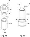
- Fig. 12-15 show various embodiments.
- the sleeve 86 can be screwed to the base body 60 of the bolt 50 ( Fig. 12 ) or welded or soldered ( Fig. 13 ) or by means of a pen ( Fig. 14 ) or an embossing ( Fig. 15 ) to the base body 60.
- Fig. 12 shows the base body 60 with an external thread 88 and the sleeve 86 with a corresponding internal thread 90, which is formed on a part of the inner surface of the sleeve 86.
- the base body 60 of the bolt 50 and the sleeve 86 can thus be detachably screwed together.
- the sleeve 86 can be unscrewed from the base body 60.
- Fig. 13 shows the bolt 50 with the sleeve 86, which is attached to the base body 60 by means of a plurality of weld seams 92.
- the weld seams 92 are evenly distributed over the circumference of the base body 60 or the sleeve 86.
- Fig. 14 shows the bolt 50 with the sleeve 86 and a pin 94 which is arranged in a through hole 96 of the base body 60 of the bolt 50 and the sleeve 86 and fastens the base body 60 to the sleeve 86.
- the center axes of the through hole 96 of the base body 60 and the sleeve 86 are aligned with one another and run essentially orthogonal to the longitudinal axis of the bolt 50.
- Fig. 15 shows the bolt 50 with the sleeve 86, whereby the sleeve 86 is attached to the base body 60 by means of embossings 98.
- the embossing 98 is created by the plastic pressing of a part of the sleeve 86 into the base body 60, whereby the sleeve 86 is connected to the base body 60 by means of force and form locking.
- the embossing 98 can be introduced by a punch.
- the base body 60 has two recesses 100 (or receptacles) into which a part of the sleeve 86 is pressed.
- the base body 60 of the bolt 50 can also have one or more recesses 100 for stamping, which are point-shaped, run continuously all the way around or run partially all the way around. However, the base body 60 can also have no prefabricated recesses 100, so that a part of the sleeve 86 is pressed plastically into the material of the base body 60 by means of stamping.
Landscapes
- Engineering & Computer Science (AREA)
- Mechanical Engineering (AREA)
- General Engineering & Computer Science (AREA)
- Physics & Mathematics (AREA)
- General Physics & Mathematics (AREA)
- Automation & Control Theory (AREA)
- Refuge Islands, Traffic Blockers, Or Guard Fence (AREA)
- Lock And Its Accessories (AREA)
- Power-Operated Mechanisms For Wings (AREA)
- Rolling Contact Bearings (AREA)
Abstract
Schutztürüberwachungsmodul (16) zur Überwachung eines Zustands einer Schutztür (14), wobei das Schutztürüberwachungsmodul (16) eine Betätigeraufnahme (38) zur Aufnahme eines Betätigers (36) aufweist und dazu eingerichtet ist, ein Schutztürsignal zu erzeugen, wenn der Betätiger (36) in die Betätigeraufnahme (38) eingeführt ist, wobei die Betätigeraufnahme (38) eine Zuhaltevorrichtung (44) aufweist, die dazu ausgebildet ist, in einem aktivierten Zustand den Betätiger (36) in der Betätigeraufnahme (38) festzuhalten, wobei die Zuhaltevorrichtung (44) einen Bolzen (50) mit einer Lagerkörperaufnahme (58) und einen in der Lagerkörperaufnahme (58) drehbar gelagerten Lagerkörper (54) aufweist, der an einem freien Ende (62) des Bolzens (50), welches dazu ausgebildet ist, in dem aktivierten Zustand in den Betätiger (36) einzugreifen, angeordnet ist.


Description
Die vorliegende Erfindung betrifft ein Schutztürüberwachungsmodul zur Überwachung eines Zustands einer Schutztür.The present invention relates to a protective door monitoring module for monitoring a state of a protective door.
Gemäß einem weiteren Aspekt betrifft die vorliegende Erfindung ein Schutztürüberwachungssystem mit einer Schutztür als Zugang zu einem Sicherheitsbereich, einem Schutztürüberwachungsmodul der oben genannten Art, einem Betätiger und einer Steuerungseinheit, welche dazu eingerichtet ist, ein Schutztürsignal auszulesen und eine im Sicherheitsbereich befindliche Maschine oder Anlage in Abhängigkeit des Schutztürsignals zu steuern.According to a further aspect, the present invention relates to a protective door monitoring system with a protective door as access to a safety area, a protective door monitoring module of the above-mentioned type, an actuator and a control unit which is designed to read out a protective door signal and to control a machine or system located in the safety area depending on the protective door signal.
Schutztürüberwachungsmodule der oben genannten Art werden häufig auch als Sicherheitsschalter bezeichnet. Beispielhafte Schutztürüberwachungsmodule bzw. Sicherheitsschalter der eingangs genannten Art sind aus der
Gattungsgemäße Schutztürüberwachungsmodule werden an Schutztüren, Schutzklappen und dergleichen eingesetzt. Wenngleich vorliegend die Begriffe "Schutztürüberwachungsmodul" und "Schutztür" verwendet werden, kann das erfindungsgemäße Schutztürüberwachungsmodul an jeglicher Art von trennender Schutzeinrichtung zum Einsatz kommen. Der Begriff "Schutztür" ist im vorliegenden Sinne dementsprechend weit aufzufassen. Anstelle des allgemeinen Begriffs "trennende Schutzeinrichtung" wird daher im Folgenden ausschließlich der Begriff "Schutztür" verwendet, ohne dass dies eine Beschränkung des Schutzbereichs zur Folge haben soll.Protective door monitoring modules of this type are used on protective doors, protective flaps and the like. Although the terms "protective door monitoring module" and "protective door" are used here, the protective door monitoring module according to the invention can be used on any type of separating protective device. The term "protective door" is to be interpreted broadly in the present sense. Instead of the general term "separating protective device", the term "protective door" is therefore used exclusively in the following, without this being intended to result in a restriction of the protection area.
Schutztüren, an denen das erfindungsgemäße Schutztürüberwachungsmodul bspw. zum Einsatz kommen kann, dienen typischerweise als Zugang zu einem Sicherheitsbereich, in dem sich eine automatisiert arbeitende Maschine oder Anlage befindet. Bei der Maschine kann es sich bspw. um einen Roboter, eine Werkzeugmaschine mit schnelldrehender Spindel, eine Transport- oder Förderanlage, eine Presse oder eine andere Maschine oder Anlage handeln, von deren Betrieb eine Gefahr für Personen ausgeht, die sich in dem genannten Sicherheitsbereich bzw. im Arbeitsbereich der Maschine befinden. Das Schutztürüberwachungsmodul kann als Meldegerät dienen, mit dessen Hilfe eine Steuerungseinheit den geschlossenen Zustand der Schutztür erkennen kann. Die Steuerungseinheit ist dazu eingerichtet, das von dem Schutztürüberwachungsmodul erzeugte Schutztürsignal auszulesen und die Maschine in Abhängigkeit des Schutztürsignals zu steuern. Beispielsweise ist ein Betreiben der Maschine nur bei Vorhandensein des Schutztürsignals möglich. Die Steuerungseinheit ist also mit anderen Worten dazu eingerichtet, ein Betreiben der Maschine oder Anlage nur dann zu ermöglichen, wenn sie das Schutztürsignal von dem Schutztürüberwachungsmodul empfängt, d.h. wenn die Schutztür geschlossen ist. Wird die Schutztür hingegen im laufenden Betrieb geöffnet (sofern möglich), muss die Steuerungseinheit die Maschine oder Anlage in einen gefahrlosen Zustand bringen, in dem bspw. die Stromversorgung zu der Maschine oder Anlage abgeschaltet wird.Safety doors, on which the safety door monitoring module according to the invention can be used, for example, typically serve as access to a safety area in which an automated machine or system is located. The machine can be, for example, a robot, a machine tool with a fast-rotating spindle, a transport or conveyor system, a press or another machine or system whose operation poses a danger to people who are in the safety area mentioned or in the working area of the machine. The safety door monitoring module can serve as a signaling device with the help of which a control unit can detect the closed state of the safety door. The control unit is set up to read the safety door signal generated by the safety door monitoring module and to control the machine depending on the safety door signal. For example, the machine can only be operated if the safety door signal is present. In other words, the control unit is designed to only allow the machine or system to operate when it receives the safety door signal from the safety door monitoring module, i.e. when the safety door is closed. However, if the safety door is opened during operation (if possible), the control unit must bring the machine or system into a safe state by, for example, switching off the power supply to the machine or system.
Es gibt eine Vielzahl von Maschinen und Anlagen, von denen auch nach dem Abschalten noch für eine gewisse Zeit eine Gefahr ausgeht, bspw. weil die Maschine oder Anlage noch ausläuft. Für derartige Anwendungsfälle werden Schutztürüberwachungsmodule benötigt, die ein Öffnen der Schutztür so lange verhindern, bis die Maschine oder Anlage ihren gefahrlosen Zustand erreicht hat. Diese Funktion wird als Zuhaltung bezeichnet.There are a large number of machines and systems that pose a risk for a certain period of time even after they have been switched off, for example because the machine or system is still running. For such applications, safety door monitoring modules are required that prevent the safety door from opening until the machine or system has reached a safe state. This function is known as guard locking.
Klassischerweise besitzen Schutztürüberwachungsmodule der vorliegenden Art einen sogenannten Betätiger und eine als Gegenstück dazu fungierende Betätigeraufnahme. Die Betätigeraufnahme ist Teil eines Grundgeräts, in dem typischerweise weitere elektronische Bauteile untergebracht sind und von dem meist die Anschlussleitungen ausgehen, die das Schutztürüberwachungsmodul mit der Steuerungseinheit verbinden. Dementsprechend ist das Grundgerät mit der Betätigeraufnahme vorzugsweise an einem unbeweglichen Teil der Schutztür (z.B. an einer Türzarge) angeordnet, während der Betätiger vorzugsweise an einem beweglichen Teil der Schutztür (z.B. an einem beweglichen Türflügel) angeordnet ist. Dies hat den Vorteil, dass der Teil des Schutztürüberwachungsmoduls, welcher an dem beweglichen Teil der Schutztür angeordnet ist, nicht mit Strom versorgt werden muss, da in der Regel nur das Grundgerät des Schutztürüberwachungsmoduls mit Strom versorgt werden muss.Typically, safety door monitoring modules of this type have a so-called actuator and an actuator holder that acts as a counterpart to it. The actuator holder is part of a base unit, which typically houses other electronic components and from which the connecting cables that connect the safety door monitoring module to the control unit usually originate. Accordingly, the base unit with the actuator holder is preferably arranged on a stationary part of the safety door (e.g. on a door frame), while the actuator is preferably arranged on a moving part of the safety door (e.g. on a moving door leaf). This has the advantage that the part of the safety door monitoring module that is arranged on the moving part of the safety door does not have to be supplied with power, since usually only the base unit of the safety door monitoring module needs to be supplied with power.
Bei geschlossener Schutztür greift der Betätiger in die Betätigeraufnahme, was mit Hilfe eines oder mehrerer Sensoren detektiert wird. Bei einem Schutztürüberwachungsmodul mit Zuhaltung wird der Betätiger außerdem in der Betätigeraufnahme gegen ein Zurückziehen blockiert bzw. verriegelt. Die sogenannte Zuhaltung weist eine Verriegelungseinrichtung zum Verriegeln des Betätigers in der Betätigeraufnahme auf.When the safety door is closed, the actuator reaches into the actuator holder, which is detected using one or more sensors. In a safety door monitoring module with guard locking, the actuator is also blocked or locked in the actuator holder to prevent it from being pulled back. The so-called guard locking has a locking device for locking the actuator in the actuator holder.
In dem letztgenannten Fall erfüllt das Schutztürüberwachungsmodul also zwei Funktionen, nämlich einerseits eine Detektionsfunktion, mit dessen Hilfe die Schließposition der Schutztür detektiert wird, und andererseits eine Zuhaltefunktion, die ein Öffnen der Schutztür so lange verhindert, wie der Betätiger in der Betätigeraufnahme verriegelt ist. Die Freigabe des Betätigers kann bspw. über einen elektromotorischen Aktor erfolgen, der von der Steuerungseinheit betätigt wird, sobald die überwachte Maschine oder Anlage ihren sicheren Zustand eingenommen hat.In the latter case, the safety door monitoring module therefore fulfils two functions, namely a detection function, which is used to detect the closed position of the safety door, and a locking function, which prevents the safety door from opening as long as the actuator is locked in the actuator holder. The actuator can be released, for example, via an electromotive actuator that is operated by the control unit as soon as the monitored machine or system has reached its safe state.
Ein Schutztürüberwachungsmodul dieser Art wird von der Anmelderin unter dem Namen PSENmlock vertrieben. Dieses Schutztürüberwachungsmodul ist vielseitig einsetzbar. Der Betätiger des Schutztürüberwachungsmoduls kann im Wesentlichen stab- bzw. stiftförmig und die als Gegenstück dazu fungierende Betätigeraufnahme eine durchgängige Nut, eine U-förmige Öffnung oder ein Sack- oder Durchgangsloch aufweist, in welche bzw. welches der stab- bzw. stiftförmige Betätiger eingreift.A safety door monitoring module of this type is sold by the applicant under the name PSENmlock. This safety door monitoring module can be used in a variety of ways. The actuator of the safety door monitoring module can essentially be rod- or pin-shaped and the actuator holder acting as a counterpart can have a continuous groove, a U-shaped opening or a blind or through hole into which the rod- or pin-shaped actuator engages.
Es hat sich gezeigt, dass wiederholte Schließ- und Öffnungsvorgänge der Schutztüre nach bestimmungsgemäßem Gebrauch zu Materialverschleiß an dem Betätiger und der Zuhaltevorrichtung bzw. Betätigeraufnahme führen. Dieser Verschleiß kann dazu führen, dass eine geforderte Lebensdauer des Schutztürüberwachungsmoduls mit einer vorgegebenen Anzahl von Schließ- und Öffnungsvorgänge nicht erfüllt werden kann. Zudem kann hierdurch ein Sicherheitsrisiko entstehen, da die Zuhaltefunktion nicht mehr ausreichend sicher garantiert werden kann.It has been shown that repeated closing and opening of the safety door after intended use leads to material wear on the actuator and the locking device or actuator holder. This wear can lead to the required service life of the safety door monitoring module not being met with a specified number of closing and opening operations. This can also result in a safety risk, as the locking function can no longer be guaranteed with sufficient safety.
Es ist daher eine Aufgabe der vorliegenden Erfindung, ein Schutztürüberwachungsmodul bereitzustellen, welches eine erhöhte Lebensdauer und/oder verbesserte Zuverlässigkeit aufweist.It is therefore an object of the present invention to provide a protective door monitoring module which has an increased service life and/or improved reliability.
Diese Aufgabe wird ausgehend von einem Schutztürüberwachungsmodul der eingangs genannten Art dadurch gelöst, dass das Schutztürüberwachungsmodul zur Überwachung eines Zustands einer Schutztür eine Betätigeraufnahme zur Aufnahme eines Betätigers aufweist und dazu eingerichtet ist, ein Schutztürsignal zu erzeugen, wenn der Betätiger in die Betätigeraufnahme eingeführt ist, wobei die Betätigeraufnahme eine Zuhaltevorrichtung aufweist, die dazu ausgebildet ist, in einem aktivierten Zustand den Betätiger in der Betätigeraufnahme festzuhalten, wobei die Zuhaltevorrichtung einen Bolzen mit einer Lagerkörperaufnahme und einem in der Lagerkörperaufnahme drehbar gelagerten Lagerkörper aufweist, der an einem freien Ende des Bolzens, welches dazu ausgebildet ist, in dem aktivierten Zustand in den Betätiger einzugreifen, angeordnet ist.This object is achieved on the basis of a protective door monitoring module of the type mentioned at the outset in that the protective door monitoring module for monitoring a state of a protective door has an actuator receptacle for receiving an actuator and is designed to generate a protective door signal when the actuator is inserted into the actuator receptacle, wherein the actuator receptacle has a locking device which is designed to hold the actuator in the actuator receptacle in an activated state, wherein the locking device has a bolt with a bearing body receptacle and a bearing body which is rotatably mounted in the bearing body receptacle and which is arranged on a free end of the bolt which is designed to engage in the actuator in the activated state.
Die erfindungsgemäße Zuhaltevorrichtung weist also insbesondere einen Lagerkörper auf, der drehbar in dem Bolzen gelagert ist und derart angeordnet ist, dass der Lagerkörper mit dem Betätiger in Kontakt sein kann. Im Gegensatz zu herkömmlichen Zuhaltevorrichtungen, bei denen ein Bolzen auf einem Betätiger gleitet, kann gemäß der vorliegenden Erfindung der in dem Bolzen gelagerte Lagerkörper auf dem Betätiger abrollen. Die vorliegende Erfindung ermöglicht es somit, vorteilhafterweise Reibung und/oder Verschleiß in dem Reibkontakt zwischen Zuhaltevorrichtung und Betätiger zu reduzieren und somit auch Verschluss- und Öffnungskräfte in dem Schutztürüberwachungsmodul zu minimieren.The locking device according to the invention therefore has in particular a bearing body which is rotatably mounted in the bolt and is arranged such that the bearing body can be in contact with the actuator. In contrast to conventional locking devices in which a bolt slides on an actuator, according to the present invention the bearing body mounted in the bolt can roll on the actuator. The present invention thus makes it possible to advantageously reduce friction and/or wear in the frictional contact between the locking device and the actuator and thus also to minimize closing and opening forces in the protective door monitoring module.
Der Lagerkörper kann beim Einführen des Betätigers in die Betätigeraufnahme mit dem Betätiger in Kontakt sein, um das Einführen des Betätigers in die Betätigeraufnahme zu vereinfachen und/oder um Reibung und/oder Verschleiß zwischen der Zuhaltevorrichtung und dem Betätiger zu reduzieren. Rollt der Lagerkörper auf dem Betätiger während des Einführens des Betätigers in die Betätigeraufnahme ab, anstatt auf dem Betätiger zu gleiten, so ist der Reibkontakt vorwiegend durch Rollreibung anstatt durch Gleitreibung charakterisiert. Somit kann die Reibung im Reibkontakt reduziert werden. Gleiches gilt für den Öffnungsvorgang der Schutztür, bei dem der Betätiger aus der Betätigeraufnahme herausgeführt wird.The bearing body can be in contact with the actuator when it is inserted into the actuator holder in order to simplify the insertion of the actuator into the actuator holder and/or to reduce friction and/or wear between the locking device and the actuator. If the bearing body rolls on the actuator when the actuator is inserted into the actuator holder instead of sliding on the actuator, the frictional contact is predominantly characterized by rolling friction instead of sliding friction. This allows the friction in the frictional contact to be reduced. The same applies to the opening process of the protective door, during which the actuator is guided out of the actuator holder.
Somit ist auf konstruktiv einfache und kostengünstige Art und Weise eine Lösung geschaffen, den Verschleiß zwischen der Zuhaltevorrichtung und dem Betätiger zu reduzieren und die Zuverlässigkeit der Zuhaltevorrichtung zu erhöhen.This creates a structurally simple and cost-effective solution to reduce the wear between the locking device and the actuator and to increase the reliability of the locking device.
Die vorliegende Erfindung ermöglicht zudem vorteilhafterweise eine freiere und somit einfachere Gestaltung des Bolzens. Insbesondere die Form des Bolzens kann unabhängiger von dem Betätiger gestaltet werden. Gleichzeitig kann der Lagerkörper unabhängig von dem Rest des Bolzens beispielsweise hinsichtlich Oberflächengüte bearbeitet werden, um die Eigenschaften des Reibkontakts zu verbessern. Dies kann sich vereinfachend auf die Fertigung der Zuhaltevorrichtung und/oder des Betätigers auswirken.The present invention also advantageously enables a freer and therefore simpler design of the bolt. In particular, the shape of the bolt can be designed more independently of the actuator. At the same time, the bearing body can be machined independently of the rest of the bolt, for example with regard to surface quality, in order to improve the properties of the frictional contact. This can have a simplifying effect on the manufacture of the locking device and/or the actuator.
Zudem ermöglicht es die vorliegende Erfindung, den Lagerkörper unabhängig von dem Rest des Bolzens auszutauschen. Auch wenn die Zuhaltevorrichtung gemäß der vorliegenden Erfindung gegenüber herkömmlichen Zuhaltevorrichtungen mit einem reduzierten Verschleiß einhergeht, so kann dennoch der Lagerkörper mit fortlaufendem Gebrauch verschleißen. In diesem Fall ermöglicht die vorliegende Erfindung gezielt nur den Lagerkörper auszutauschen und die übrigen Teile des Bolzens weiter zu benutzen. Somit können die Bauteile der Zuhaltevorrichtung nachhaltig genutzt werden.In addition, the present invention makes it possible to replace the bearing body independently of the rest of the bolt. Even if the locking device according to the present invention is associated with reduced wear compared to conventional locking devices, the bearing body can still wear out with continued use. In this case, the present invention makes it possible to specifically replace only the bearing body and continue to use the remaining parts of the bolt. The components of the locking device can therefore be used sustainably.
Um die Eigenschaften des Reibkontakts (z.B. Reibungskoeffizient zwischen den Reibkontaktpartnern) wie gefordert einzustellen, werden gewöhnlicherweise insbesondere die Werkstoffe der Reibkontaktpartner aufeinander abgestimmt. Die vorliegende Erfindung ermöglicht es zudem, dass die Zuhaltevorrichtung verschiedene Materialen (Werkstoffe) aufweisen kann. Dadurch können die Werkstoffe der Reibkontaktpartner besser aufeinander abgestimmt werden.In order to adjust the properties of the friction contact (e.g. friction coefficient between the friction contact partners) as required, the materials of the friction contact partners are usually matched to one another. The present invention It also allows the locking device to be made of different materials. This allows the materials of the friction contact partners to be better coordinated with one another.
Gemäß der vorliegenden Erfindung kann der Lagerkörper einen Werkstoff aufweisen, der unterschiedlich von dem Werkstoff des Bolzens ist. Somit kann durch eine selektierte Werkstoffkombination von Lagerkörper und Betätiger die Eigenschaften des Reibkontakts festgelegt werden, wobei gleichzeitig die Auswahl des Werkstoffs des Bolzens unabhängiger von dem Werkstoff des Betätigers gewählt werden kann.According to the present invention, the bearing body can have a material that is different from the material of the bolt. Thus, the properties of the frictional contact can be determined by a selected material combination of the bearing body and actuator, while at the same time the selection of the material of the bolt can be made more independent of the material of the actuator.
Die oben genannt Aufgabe ist daher vollständig gelöst.The above task is therefore completely solved.
Gemäß einer bevorzugten Ausgestaltung weist der Bolzen eine Verliersicherung auf, die dazu ausgebildet ist, den drehbar gelagerten Lagerkörper verliersicher an dem Bolzen zu halten.According to a preferred embodiment, the bolt has a loss prevention device which is designed to hold the rotatably mounted bearing body captively on the bolt.
Mithilfe der Verliersicherung ist der Lagerköper dauerhaft in der gewünschten Position und/oder Ausrichtung im Bolzen gehalten. Somit kann die Zuverlässigkeit des Schutztürüberwachungsmoduls verbessert werden.With the help of the loss protection, the bearing body is permanently held in the desired position and/or alignment in the bolt. This can improve the reliability of the protective door monitoring module.
Gemäß einer weiteren Ausgestaltung ist die Verliersicherung mittels einer Querschnittsverengung der Lagerkörperaufnahme gebildet.According to a further embodiment, the loss prevention device is formed by means of a cross-sectional narrowing of the bearing body receptacle.
Die Lagerkörperaufnahme ist gemäß dieser Ausgestaltung also verengt, um den Lagerkörper in der gewünschten Position und/oder Ausrichtung im Bolzen zu halten. Die Querschnittsverengung kann als Rastelement für den Lagerkörper fungieren. Dies ermöglicht eine einfache und kostengünstige Fertigung der Zuhaltevorrichtung.According to this design, the bearing body holder is narrowed in order to hold the bearing body in the desired position and/or alignment in the bolt. The cross-sectional constriction can act as a locking element for the bearing body. This enables simple and cost-effective production of the locking device.
Gemäß einer anderen Ausgestaltung ist der Durchmesser der Querschnittsverengung kleiner als der Durchmesser des Lagerkörpers.According to another embodiment, the diameter of the cross-sectional constriction is smaller than the diameter of the bearing body.
Dadurch ist sichergestellt, dass sich der drehbar gelagerte Lagerkörper nicht aus der Lagerkörperaufnahme herauslösen kann. Somit wird der Lagerkörper sicher in der gewünschten Position und/oder Ausrichtung im Bolzen gehalten.This ensures that the rotatably mounted bearing body cannot come loose from the bearing body holder. The bearing body is thus held securely in the desired position and/or alignment in the bolt.
Gemäß einer bevorzugten Ausgestaltung ist der Lagerkörper eine Kugel.According to a preferred embodiment, the bearing body is a ball.
Eine Kugel hat den Vorteil, dass sich die Kugel aufgrund ihrer Symmetrie als multidirektional wirkender Lagerkörper verwenden lässt. Somit lässt sich der Betätiger aus jeder Richtung in den Betätiger einführen, während die Kugel als Lagerkörper die genannte Funktion der Reibungs- und Verschleißreduktion übernimmt.A ball has the advantage that, due to its symmetry, it can be used as a multidirectional bearing body. This means that the actuator can be inserted into the actuator from any direction, while the ball as a bearing body takes on the aforementioned function of reducing friction and wear.
Der Lagerkörper kann jedoch auch eine andere geeignete Form, wie beispielsweise die eines Kreiszylinders, aufweisen, welche sich insbesondere zum Drehen bzw. Abrollen auf dem Betätiger eignet.However, the bearing body can also have another suitable shape, such as that of a circular cylinder, which is particularly suitable for rotating or rolling on the actuator.
Gemäß einer Ausgestaltung weist die Lagerkörperaufnahme einen ersten Abschnitt, der konisch, kugelkalottenförmig oder zylindrisch ist, und einen zweiten Abschnitt, der zylindrisch ist, auf.According to one embodiment, the bearing body receptacle has a first portion which is conical, spherical cap-shaped or cylindrical, and a second portion which is cylindrical.
Der erste Abschnitt kann insbesondere zumindest zu einem Teil in Kontakt mit dem Lagerkörper sein und/oder als Aufnahme für einen Lagereinsatz fungieren. Der zweite Abschnitt kann insbesondere zumindest zu einem Teil in Kontakt mit dem Lagerkörper sein und/oder als Ummantelung bzw. Gehäuse (insbesondere gegen das Eindringen von Fremdkörpern) fungieren.The first section can in particular be at least partially in contact with the bearing body and/or function as a receptacle for a bearing insert. The second section can in particular be at least partially in contact with the bearing body and/or function as a casing or housing (in particular to prevent the ingress of foreign bodies).
Gemäß einer Ausgestaltung ist mehr als die Hälfte des Lagerkörpers innerhalb der Lagerkörperaufnahme angeordnet.According to one embodiment, more than half of the bearing body is arranged within the bearing body receptacle.
Damit ist insbesondere mehr als die Hälfte des Volumens des Lagerkörpers gemeint. Somit ist der Großteil des Lagerkörpers in der Lagerkörperaufnahme geschützt. Der andere Teil des Lagerkörpers, also weniger als die Hälfte (des Volumens) des Lagerkörpers, ist außerhalb der Lagerkörperaufnahme angeordnet und kann mit dem Betätiger in Kontakt sein.This means in particular more than half of the volume of the bearing body. Thus, the majority of the bearing body is protected in the bearing body holder. The other part of the bearing body, i.e. less than half (of the volume) of the bearing body, is located outside the bearing body holder and can be in contact with the actuator.
Gemäß einer weiteren Ausgestaltung ist der Bolzen mittels einer Federeinrichtung vorgespannt.According to a further embodiment, the bolt is preloaded by means of a spring device.
Die Federeinrichtung ist dazu ausgebildet, die Zuhaltevorrichtung zu aktivieren, sodass die Zuhaltevorrichtung den Betätiger in der Betätigeraufnahme festhält. Bevorzugterweise greift die Federeinrichtung an einer dem freien Ende entgegengesetzten Seite des Bolzens an und kann den Lagerkörper in Eingriff mit dem Betätiger drücken. Bei dem Ein- und Ausführen des Bolzens in bzw. aus dem Betätiger kann der Bolzen entgegen der Federkraft ausweichen.The spring device is designed to activate the locking device so that the locking device holds the actuator in the actuator holder. Preferably, the spring device acts on a side of the bolt opposite the free end and can press the bearing body into engagement with the actuator. When the bolt is inserted and removed from the actuator, the bolt can give way against the spring force.
Gemäß einer bevorzugten Ausgestaltung weist der Bolzen einen Grundkörper und eine darin eingesetzte Lagerschale auf, die zumindest einen Teil der Lagerkörperaufnahme bildet.According to a preferred embodiment, the bolt has a base body and a bearing shell inserted therein, which forms at least part of the bearing body receptacle.
Daher ist der Bolzen zumindest zwei- bzw. dreiteilig aufgebaut. Eine Lagerschale als separates Bauteil, welches in den Bolzen eingesetzt ist, ermöglicht eine einfache Herstellung des Bolzens.The bolt is therefore constructed in at least two or three parts. A bearing shell as a separate component, which is inserted into the bolt, enables the bolt to be manufactured easily.
Der Lagerkörper ist drehbar in der (eingesetzten) Lagerschale angeordnet. Die Lagerschale kann dazu ausgebildet sein, den Lagerkörper so aufzunehmen, dass der Lagerkörper auf der Lagerschale abrollen kann. Vorteilhafterweise können somit reduzierte Anforderungen an die Ausgestaltung des Bolzens sowie die Ausgestaltung der Lagerkörperaufnahme gestellt werden, sodass die Herstellung des Bolzens vereinfacht werden kann. Zusätzlich kann der Reibkontakt geschmiert sein.The bearing body is arranged rotatably in the (inserted) bearing shell. The bearing shell can be designed to accommodate the bearing body in such a way that the bearing body can roll on the bearing shell. Advantageously, reduced requirements can thus be placed on the design of the bolt and the design of the bearing body holder, so that the manufacture of the bolt can be simplified. In addition, the frictional contact can be lubricated.
Bevorzugterweise ist die Lagerkörperaufnahme auf einer dem Lagerkörper entgegengesetzten Seite konisch ausgebildet.Preferably, the bearing body receptacle is conical on a side opposite the bearing body.
Dies ermöglicht vorteilhafterweise eine relative einfache Fertigung der Lagerkörperaufnahme, beispielsweise mittels Vornahme einer Bohrung in den Bolzen hinein. Weist der Bolzen eine Lagerschale auf, so kann vorteilhafterweise nur ein Loch gebohrt werden, um die Lagerschale einzusetzen.This advantageously allows a relatively simple manufacture of the bearing body holder, for example by drilling a hole into the bolt. If the bolt has a bearing shell, then advantageously only one hole can be drilled to insert the bearing shell.
Gemäß einer Ausgestaltung weist der Grundkörper des Bolzens ein erstes Material und die Lagerschale ein von dem ersten Material unterschiedliches, zweites Material auf.According to one embodiment, the base body of the bolt has a first material and the bearing shell has a second material that is different from the first material.
Vorteilhafterweise ermöglicht diese Ausgestaltung, dass die eingesetzte Lagerschale ein Material (Werkstoff) aufweist, das unterschiedlich von dem Material des Bolzens ist. Somit können die Eigenschaften des Reibkontakts zwischen Lagerkörper und Lagerschale unabhängig von dem Material des Bolzens gezielt eingestellt werden (insbesondere hinsichtlich Reduzierung von Reibung und Verschleiß).This design advantageously allows the bearing shell used to have a material that is different from the material of the bolt. This means that the properties of the frictional contact between the bearing body and the bearing shell can be specifically adjusted independently of the material of the bolt (particularly with regard to reducing friction and wear).
Gemäß einer anderen Ausgestaltung weist der Bolzen eine Hülse auf, die an einem Grundkörper des Bolzens befestigt ist und zumindest einen Teil der Lagerkörperaufnahme bildet.According to another embodiment, the bolt has a sleeve which is fastened to a base body of the bolt and forms at least part of the bearing body receptacle.
Die Lagerkörperaufnahme ist gemäß dieser Ausgestaltung also mindestens zweiteilig ausgestaltet, wobei zumindest ein Teil der Lagerkörperaufnahme durch den Grundkörper des Bolzens und die daran befestigte Hülse gebildet wird. Vorteilhafterweise können somit an den Grundkörper des Bolzens hinsichtlich Herstellung reduzierte Anforderungen gestellt werden, sodass eine kostengünstige und einfache Herstellung des Bolzens ermöglicht wird.According to this embodiment, the bearing body holder is designed in at least two parts, with at least one part of the bearing body holder being formed by the base body of the bolt and the sleeve attached to it. Advantageously, reduced manufacturing requirements can therefore be placed on the base body of the bolt, enabling the bolt to be manufactured inexpensively and easily.
Gemäß einer weiteren Ausgestaltung bildet die Hülse zumindest einen Teil der Verliersicherung. Bevorzugterweise bildet die Hülse dabei einen Teil der Querschnittsverengung der Lagerkörperaufnahme. Die Hülse kann somit als Rastelement für den Lagerkörper fungieren.According to a further embodiment, the sleeve forms at least part of the loss prevention device. Preferably, the sleeve forms part of the cross-sectional constriction of the bearing body receptacle. The sleeve can thus function as a locking element for the bearing body.
Vorteilhafterweise können somit an den Grundkörper des Bolzens hinsichtlich Fertigung der Lagerkörperaufnahme weiter reduzierte Anforderungen gestellt werden, sodass die Herstellung des Bolzens vereinfacht werden kann. Zudem kann vorteilhafterweise der Lagerkörper leichter vormontiert werden, sodass die Hülse zum Beispiel als Verliersicherung für den Montagevorgang dienen kann.Advantageously, further reduced requirements can be placed on the base body of the bolt with regard to the manufacture of the bearing body holder, so that the The manufacture of the bolt can be simplified. In addition, the bearing body can be pre-assembled more easily, so that the sleeve can serve as a loss protection for the assembly process, for example.
Die Hülse kann an dem Grundkörper des Bolzens lösbar oder nicht lösbar befestigt sein. Insbesondere kann die Hülse kraft- und formschlüssig an dem Grundkörper befestigt sein, wie beispielsweise mittels eines Gewindes, einem Niet oder einem Stift. Die Hülse kann ebenfalls oder zusätzlich stoffschlüssig mit dem Grundkörper verbunden sein, insbesondere verklebt, verlötet und/oder verschweißt sein. Die Hülse kann beispielsweise auch auf den Grundkörper aufgeschrumpft sein. Eine lösbar an den Grundkörper befestigte Hülse kann sich dahingehend vorteilhaft auswirken, dass der Lagerkörper einfach ausgetauscht werden kann - beispielsweise nachdem eine bestimmte Anzahl von Schließ- und Öffnungsvorgängen des Betätigers und/oder eine vorgegebene Verschleißgrenze überschritten wurde.The sleeve can be attached to the base body of the bolt in a detachable or non-detachable manner. In particular, the sleeve can be attached to the base body in a force-fitting or form-fitting manner, for example by means of a thread, a rivet or a pin. The sleeve can also or additionally be connected to the base body in a material-fitting manner, in particular glued, soldered and/or welded. The sleeve can also be shrunk onto the base body, for example. A sleeve that is detachably attached to the base body can have the advantage that the bearing body can be easily replaced - for example after a certain number of closing and opening operations of the actuator and/or a specified wear limit has been exceeded.
Gemäß einer Ausgestaltung weist der Bolzen eine Vielzahl von Lagerkugeln auf, die in der Lagerkörperaufnahme angeordnet sind.According to one embodiment, the bolt has a plurality of bearing balls which are arranged in the bearing body receptacle.
Der Lagerkörper und die Lagerkugeln können dazu ausgebildet sein, miteinander in Kontakt zu sein und aufeinander abzurollen. Vorteilhafterweise können die Lagerkugeln ein Material aufweisen, das unterschiedlich von dem Material des Bolzens ist. Dadurch können die Eigenschaften des Reibkontakts zwischen Lagerkörper und Lagerkugeln insbesondere einfacher unabhängiger von dem Bolzen gezielt eingestellt werden (insbesondere hinsichtlich Reduzierung von Reibung und Verschleiß).The bearing body and the bearing balls can be designed to be in contact with one another and to roll on one another. The bearing balls can advantageously have a material that is different from the material of the bolt. This makes it easier to specifically adjust the properties of the frictional contact between the bearing body and the bearing balls independently of the bolt (in particular with regard to reducing friction and wear).
Bevorzugterweise weisen die Lagerkugeln jeweils einen Durchmesser auf, der jeweils kleiner als der Durchmesser des Lagerkörpers ist. Weiter bevorzugt weisen die Lagerkugeln jeweils den gleichen Durchmesser auf.Preferably, the bearing balls each have a diameter that is smaller than the diameter of the bearing body. More preferably, the bearing balls each have the same diameter.
Vorzugsweise weist der Betätiger zumindest zu einem Teil (insbesondere in dem Kontaktbereich mit der Zuhaltevorrichtung im aktivierten Zustand der Zuhaltevorrichtung) als Werkstoff eine Chrom-Nickel-Molybdän-Edelstahllegierung und/oder der Lagerkörper einen Wälzlagerstahl und/oder der Bolzen einen Automaten- oder einen Einsatzstahl auf.Preferably, the actuator has at least a part (in particular in the contact area with the locking device in the activated state of the locking device) as Material is a chromium-nickel-molybdenum stainless steel alloy and/or the bearing body is a rolling bearing steel and/or the bolt is a free-cutting or case-hardening steel.
Wie eingangs bereits erwähnt, betrifft ein weiterer Aspekt der vorliegenden Erfindung ein Schutztürüberwachungssystem, welches eine Schutztür der zuvor genannten Art (mit einem erfindungsgemäßem Schutztürüberwachungsmodul), einen Betätiger und eine Steuerungseinheit aufweist.As already mentioned at the beginning, a further aspect of the present invention relates to a protective door monitoring system which has a protective door of the aforementioned type (with a protective door monitoring module according to the invention), an actuator and a control unit.
Vorzugsweise handelt es sich bei dem ersten Teil der Schutztür, an dem das Grundgerät angeordnet ist, um einen unbewegten Teil der Schutztür (z.B. um einen Türrahmen oder eine Türzarge). Äquivalent dazu handelt es sich bei dem zweiten Teil der Schutztür, an dem der Betätiger angeordnet ist, vorzugsweise um ein bewegliches Türelement (z.B. ein Türflügel). Die Anordnung des Grundgeräts an dem unbewegten Teil der Schutztür hat den Vorteil, dass eine Stromversorgung des am beweglichen Teil der Schutztür montierten Teils des Schutztürüberwachungsmoduls unterbleiben kann, da typischerweise nur das Grundgerät des Schutztürüberwachungsmoduls mit Strom versorgt werden muss.Preferably, the first part of the safety door on which the base unit is arranged is a stationary part of the safety door (e.g. a door frame or a door casing). Equivalently, the second part of the safety door on which the actuator is arranged is preferably a movable door element (e.g. a door leaf). The arrangement of the base unit on the stationary part of the safety door has the advantage that the part of the safety door monitoring module mounted on the movable part of the safety door does not need to be supplied with power, since typically only the base unit of the safety door monitoring module needs to be supplied with power.
Bevorzugterweise weist der Betätiger eine Aufnahme auf, die dazu ausgebildet ist, die Zuhaltevorrichtung im aktivierten Zustand aufzunehmen. Weiter bevorzugt ist die Aufnahme des Betätigers dazu ausgebildet, in Kontakt mit dem Lagerkörper zu sein. Die Aufnahme des Betätigers weist daher bevorzugterweise eine der Form des Lagerkörpers entsprechende Gegenform auf, insbesondere eine konische, kugelkalottenförmige oder zylindrische Gegenform.The actuator preferably has a receptacle which is designed to accommodate the locking device in the activated state. The receptacle of the actuator is further preferably designed to be in contact with the bearing body. The receptacle of the actuator therefore preferably has a counter-shape corresponding to the shape of the bearing body, in particular a conical, spherical cap-shaped or cylindrical counter-shape.
Es versteht sich, dass die vorstehend genannten und die nachstehend noch erläuterten Merkmale nicht nur in der jeweils angegebenen Kombination, sondern auch in anderen Kombinationen oder in Alleinstellung verwendbar sind, ohne den Rahmen der vorliegenden Erfindung zu verlassen.It is understood that the features mentioned above and those explained below can be used not only in the combination specified in each case, but also in other combinations or on their own, without departing from the scope of the present invention.
Ausführungsbeispiele der Erfindung sind in den Zeichnungen dargestellt und werden in der nachfolgenden Beschreibung näher erläutert. Es zeigen:
- Fig. 1
- eine schematische Darstellung eines Schutztürüberwachungssystems gemäß einem Ausführungsbeispiel der vorliegenden Erfindung;
- Fig. 2
- eine perspektivische Ansicht eines Schutztürüberwachungsmoduls mit einem Betätiger gemäß einem Ausführungsbeispiel der vorliegenden Erfindung;
- Fig. 3A
- eine Front-Ansicht des in
Fig. 2 gezeigten Schutztürüberwachungsmoduls mit dem Betätiger; - Fig. 3B
- eine Schnittdarstellung des in
Fig. 2 gezeigten Schutztürüberwachungsmoduls mit Betätiger; - Fig. 4
- eine perspektivische Ansicht des Betätigers gemäß einem Ausführungsbeispiel der vorliegenden Erfindung;
- Fig. 5
- eine Schnittdarstellung eines in dem Schutztürüberwachungsmodul verwendeten Bolzens gemäß einem ersten Ausführungsbeispiel der vorliegenden Erfindung;
- Fig. 6
- eine Schnittdarstellung zur schematischen Veranschaulichung eines Herstellungsschritts zur Herstellung des in
Fig. 5 gezeigten Bolzens; - Fig. 7
- eine Schnittdarstellung des Bolzens gemäß einem zweiten Ausführungsbeispiel der vorliegenden Erfindung;
- Fig. 8
- eine Schnittdarstellung des Bolzens gemäß einem dritten Ausführungsbeispiel der vorliegenden Erfindung;
- Fig. 9
- eine Schnittdarstellung des Bolzens gemäß einem vierten Ausführungsbeispiel der vorliegenden Erfindung;
- Fig. 10
- eine Schnittdarstellung des Bolzens gemäß einem fünften Ausführungsbeispiel der vorliegenden Erfindung;
- Fig. 11A
- eine Schnittdarstellung des Bolzens gemäß einem sechsten Ausführungsbeispiel der vorliegenden Erfindung;
- Fig. 11B
- eine erste Explosionsdarstellung des in
Fig. 11A gezeigten Bolzens; - Fig. 11C
- eine zweite Explosionsdarstellung des in
Fig. 11A gezeigten Bolzens; - Fig. 12
- eine Explosionsdarstellung des Bolzens gemäß einem siebten Ausführungsbeispiel der vorliegenden Erfindung;
- Fig. 13
- eine perspektivische Ansicht des Bolzens gemäß einem achten Ausführungsbeispiel der vorliegenden Erfindung;
- Fig. 14
- eine perspektivische Ansicht des Bolzens gemäß einem neunten Ausführungsbeispiel der vorliegenden Erfindung; und
- Fig. 15
- eine perspektivische Ansicht des Bolzens gemäß einem zehnten Ausführungsbeispiel der vorliegenden Erfindung.
- Fig.1
- a schematic representation of a protective door monitoring system according to an embodiment of the present invention;
- Fig. 2
- a perspective view of a protective door monitoring module with an actuator according to an embodiment of the present invention;
- Fig. 3A
- a front view of the
Fig. 2 shown protective door monitoring module with the actuator; - Fig. 3B
- a sectional view of the
Fig.2 shown protective door monitoring module with actuator; - Fig.4
- a perspective view of the actuator according to an embodiment of the present invention;
- Fig.5
- a sectional view of a bolt used in the protective door monitoring module according to a first embodiment of the present invention;
- Fig.6
- a sectional view for schematically illustrating a manufacturing step for producing the
Fig.5 bolt shown; - Fig.7
- a sectional view of the bolt according to a second embodiment of the present invention;
- Fig.8
- a sectional view of the bolt according to a third embodiment of the present invention;
- Fig.9
- a sectional view of the bolt according to a fourth embodiment of the present invention;
- Fig.10
- a sectional view of the bolt according to a fifth embodiment of the present invention;
- Fig. 11A
- a sectional view of the bolt according to a sixth embodiment of the present invention;
- Fig. 11B
- a first exploded view of the
Fig. 11A bolt shown; - Fig. 11C
- a second exploded view of the
Fig. 11A bolt shown; - Fig. 12
- an exploded view of the bolt according to a seventh embodiment of the present invention;
- Fig. 13
- a perspective view of the bolt according to an eighth embodiment of the present invention;
- Fig. 14
- a perspective view of the bolt according to a ninth embodiment of the present invention; and
- Fig. 15
- a perspective view of the bolt according to a tenth embodiment of the present invention.
Das Schutztürüberwachungssystem 10 beinhaltet hier einen Roboter 12, dessen Arbeitsbereich mit Hilfe einer Schutztür 14 abgesichert ist. An der Schutztür 14 ist ein Schutztürüberwachungsmodul 16 gemäß der vorliegenden Erfindung angeordnet.The protective
Das Schutztürüberwachungsmodul 16 umfasst ein Türteil 17, welches an dem beweglichen Türelement (Türflügel) der Schutztür 14 angeordnet ist, und ein Rahmenteil 18, das an einem unbeweglichen zweiten Teil 20 der Schutztür 14 angeordnet ist. In dem dargestellten Ausführungsbeispiel handelt es sich bei dem unbeweglichen zweiten Teil 20 der Schutztür 14 um einen Türrahmen bzw. eine Türzarge. In anderen Ausführungsbeispielen kann dieser zweite unbewegliche Teil 20 der Schutztür 14 auch ein zweiter Türflügel einer zweiteiligen Schutztür sein.The safety
Das Rahmenteil 18 des Schutztürüberwachungsmoduls 16 ist über zwei Leitungen 22, 24 mit einem Sicherheitsschaltgerät 26 verbunden. Das Sicherheitsschaltgerät 26 ist bspw. ein Sicherheitsschaltgerät aus der Reihe PNOZ<®>, das von der Anmelderin der vorliegenden Erfindung vertrieben wird. Es handelt sich hierbei um ein mehrkanalig-redundantes Sicherheitsschaltgerät, das dazu ausgebildet ist, die Ausgangssignale von Meldegeräten, wie dem Schutztürüberwachungsmodul 16, auszuwerten und in Abhängigkeit davon einen elektrischen Verbraucher abzuschalten. Der elektrische Verbraucher ist in diesem Fall der Roboter 12. Dementsprechend steuert das Sicherheitsschaltgerät 26 zwei Schütze 28, 30 an, deren Arbeitskontakte in der Verbindung zwischen einer Stromversorgung 32 und dem Roboter 12 angeordnet sind.The
Alternativ zu dem Sicherheitsschaltgerät 26 könnte das Schutztürüberwachungsmodul 16 auch an eine programmierbare Sicherheitssteuerung angeschlossen sein, wie sie von der Anmelderin der vorliegenden Erfindung unter der Bezeichnung PSS<®> vertrieben wird. Das Sicherheitsschaltgerät 26 wird daher nachfolgend allgemein als Steuerungseinheit 26 des Schutztürüberwachungssystems 10 bezeichnet, ohne dadurch auf eine spezielle Ausgestaltung dieser Steuerungseinheit beschränkt zu sein. Im Folgenden werden mehrere Ausführungsbeispiele des erfindungsgemäßen Schutztürüberwachungsmoduls 16 beschrieben. Gleiche oder äquivalente Bauteile werden dabei mit den gleichen Bezugszeichen bezeichnet.As an alternative to the safety switching device 26, the protective
Wenngleich es ebenso denkbar wäre, das Grundgerät 34 als Türteil 17 des Schutztürüberwachungsmoduls 16 einzusetzen, ist dies weniger bevorzugt. In einem solchen Fall müsste die meist feste Verdrahtung mit der Steuerungseinheit 26 sowie die Stromversorgung an den beweglichen Teil der Schutztür 14 hingeführt sein, was in der Regel umständlicher ist als eine Zuführung der Leitungen 22, 24 sowie der Stromversorgung an den statischen Teil 20 der Schutztür 14.Although it would also be conceivable to use the
Der Betätiger 36 fungiert als Gegenstück zu dem Grundgerät 34 und dient der Betätigung des Grundgeräts 34. Das Grundgerät 34 weist hierzu eine entsprechende Betätigeraufnahme 38 auf, in die der Betätiger 36 einführbar ist.The actuator 36 acts as a counterpart to the
Eine Funktion des Grundgeräts 34 ist es, zu detektieren, ob der Betätiger 36 in die Betätigeraufnahme 38 eingeführt ist oder nicht. Hierzu weist der Betätiger 36 vorzugsweise einen RFID-Chip auf, der von einem in der Betätigeraufnahme 38 angeordneten Detektor auslesbar ist. Das Grundgerät 34 ist dazu eingerichtet, ein Schutztürsignal zu erzeugen, wenn der Betätiger 36 in die Betätigeraufnahme 38 eingeführt ist. Dieses Schutztürsignal wird vorzugsweise als elektrisches Signal erzeugt. Es kann sich hierbei um ein digitales, ein gepulstes, ein codiertes und/oder sonstiges (vorzugsweise elektrisches) Signal handeln.One function of the
Durch Auswertung des Schutztürsignals in der Steuerungseinheit 26 kann das Schutztürüberwachungssystem 10 zu jeder Zeit eindeutig feststellen, ob die Schutztür 14 geschlossen ist oder nicht. Der Roboter 12 kann in Abhängigkeit dessen derart gesteuert werden, dass dieser nur bei geschlossener Schutztür 14 betreibbar ist.By evaluating the safety door signal in the control unit 26, the safety
Das Grundgerät 34 weist ferner ein oder mehrere optische Kontrollanzeigen 46 auf, welche einen Zustand des Schutztürüberwachungsmoduls 16 anzeigen. Des Weiteren weist das Grundgerät 34 eine Bedieneinrichtung 48 auf, mittels derer ein Benutzer einen Zustand des Schutztürüberwachungsmoduls 16 ändern kann. Zum Beispiel ist die Bedieneinrichtung 48 ist dazu ausgebildet, die Zuhaltefunktion des Schutztürüberwachungsmoduls 16 als "Notfallentriegelung" manuell zu deaktivieren, indem die Zuhaltevorrichtung 44 entriegelt wird.The
Die Zuhaltevorrichtung 44 weist einen Bolzen 50, eine Federeinrichtung 52 und eine Verriegelungseinrichtung 53 auf. Der Bolzen 50 weist einen daran drehbar gelagerten Lagerkörper 54 auf und ist mittels der Federeinrichtung 52 vorgespannt und dazu eingerichtet, in das Durchgangsloch 42 des Betätigers 36 einzugreifen. Durch die Federvorspannung weicht der Bolzen 50 beim Ein- und Ausführen des Betätigers 36 in bzw. aus der Betätigeraufnahme 38 nach unten hin entgegen der von der Federeinrichtung 52 erzeugten Federkraft aus. Die Verriegelungseinrichtung 53 ist dazu ausgebildet, im aktivierten Zustand der Zuhaltevorrichung 44 den Bolzen 50 zu verriegeln, wodurch der Betätiger 36 in der Betätigeraufnahme 38 festgehalten wird.The locking
Das Verriegeln des Bolzens 50 kann automatisch infolge eines Signals (z.B. von der Steuereinheit 26 oder dem Schutztürüberwachungsmodul 16) oder manuell mittels der Bedieneinrichtung 48 erfolgen. Soll die Schutztür 14 wieder geöffnet werden, muss der Betätiger 36 zunächst wieder aus der Betätigeraufnahme 38 ausgeführt werden. Dafür gibt die Verriegelungseinrichtung 53 den Bolzen 50 automatisch infolge eines entsprechenden Signals oder infolge manueller Entriegelung mittels der Bedieneinrichtung 48 wieder frei.The
Die als Lagerkörper 54 verwendete Kugel 56 ist an einem freien Ende 62 des Bolzens 50 angeordnet, sodass beim Einführen des Bolzens 50 in das Betätigerelement 40 die Kugel 56 mit dem Betätigerelement 40 in Kontakt ist und auf diesem abrollen kann. Ebenso kann beim Ausführen des Bolzens aus dem Betätiger 36 die Kugel 56 auf dem Betätigerelement 40 abrollen.The ball 56 used as bearing
Die in
Der Bolzen 50 ist zumindest zum Teil als zylindrischer Körper ausgestaltet. Mit einem zylindrischen Körper ist vorliegend ein Körper gemeint, dessen Querschnittsfläche entlang der Längsachse konstant ist. Der Bolzen kann insbesondere ein Kreiszylinder (wie beispielsweise in
Der Bolzen 50 weist ferner eine Verliersicherung 78 zum Halten der Kugel 56 an dem Bolzen 50 auf. Die Lagerkörperaufnahme 58 weist hierzu an dem freien Ende 62 des Bolzens 50 eine Querschnittsverengung 80 auf, welche als Rastelement und somit als Verliersicherung 78 für die Kugel 56 fungiert. Die Querschnittsverengung 80 ist kleiner als der Durchmesser der Kugel 56.The
Die Querschnittsverengung 80 kann beispielsweise mittels eines Prägevorgangs gefertigt werden.
Bei der in
In
In den in
In der Lagerkörperaufnahme 58 ist eine Vielzahl von Lagerkugeln 74 angeordnet, auf denen die Kugel 56 abrollen kann. Die Lagerkugeln 74 sind in der Lagerkörperaufnahme 58 zwischen der Kugel 56 und dem Grundkörper 60 des Bolzens 50 angeordnet.A plurality of bearing
Die Lagerkugeln 74 weisen einen Durchmesser auf, der kleiner ist als der Durchmesser der Kugel 56. Dadurch kann die Kugel 56 gleichzeitig auf einer Vielzahl von Lagerkugeln 74 mit einer Vielzahl von Kontaktpunkten 76 abrollen. Zudem können sich die Lagerkugeln 74 als Ganzes der Kontur der Lagerkörperaufnahme 58 (insbesondere dem ersten Abschnitt 64) anpassen und sich in der Lagerköperaufnahme 58 verteilen. Der erste Abschnitt 64 der Lagerkörperaufnahme 58 ist hier kugelkalottenförmig ausgestaltet.The bearing
Im Unterschied zu den in
Die Hülse 86 kann lösbar oder nicht lösbar mit dem Grundkörper 60 des Bolzens 50 verbunden sein.
Es versteht sich, dass die in den Figuren gezeigten Ausführungsbeispiele lediglich beispielhafte Ausgestaltungen des erfindungsgemäßen Schutztürüberwachungsmoduls zeigen, die die Vorteile des erfindungsgemäßen Schutztürüberwachungsmoduls illustrativ veranschaulichen sollen. Diverse Modifikationen können an diesen Ausführungsbeispielen vorgenommen werden, ohne den Rahmen der vorliegenden Erfindung zu verlassen.It is understood that the embodiments shown in the figures merely show exemplary configurations of the protective door monitoring module according to the invention, which are intended to illustrate the advantages of the protective door monitoring module according to the invention. Various modifications can be made to these embodiments without departing from the scope of the present invention.
- 1010
- SchutztürüberwachungssystemSafety door monitoring system
- 1212
- Roboterrobot
- 1414
- SchutztürProtective door
- 1616
- SchutztürüberwachungsmodulSafety door monitoring module
- 1717
- TürteilDoor part
- 1818
- RahmenteilFrame part
- 2020
- unbeweglicher Teilimmovable part
- 22, 2422, 24
- LeitungenLines
- 2626
- SteuerungseinheitControl unit
- 28, 3028, 30
- SchützeProtect
- 3232
- StromversorgungPower supply
- 3434
- GrundgerätBasic device
- 3636
- BetätigerActuator
- 3838
- BetätigeraufnahmeActuator holder
- 4040
- BetätigerelementActuator element
- 4242
- DurchgangsbohrungThrough hole
- 4444
- ZuhaltevorrichtungLocking device
- 4646
- KontrollanzeigeControl display
- 4848
- BedieneinrichtungControl device
- 5050
- BolzenBolt
- 5252
- FedereinrichtungSpring device
- 5454
- LagerkörperBearing body
- 5656
- KugelBullet
- 5858
- LagerkörperaufnahmeBearing body holder
- 6060
- GrundkörperBase body
- 6262
- freies Endefree end
- 6464
- erster Abschnittfirst section
- 6666
- zweiter Abschnittsecond section
- 6868
- Kreiszylinder, TonneCircular cylinder, barrel
- 7070
- LagerschaleBearing shell
- 7474
- LagerkugelBearing ball
- 7676
- KontaktpunktContact point
- 7878
- VerliersicherungLoss protection
- 8080
- QuerschnittsverengungCross-sectional narrowing
- 8282
- PrägestempelEmbossing stamp
- 8484
- GegenhalterCounterholder
- 8686
- HülseSleeve
- 8888
- AußengewindeExternal thread
- 9090
- InnengewindeInternal thread
- 9292
- SchweißnahtWeld seam
- 9494
- StiftPen
- 9696
- DurchgangsbohrungThrough hole
- 9898
- VerprägungEmbossing
- 100100
- AussparungRecess
Claims (15)
wobei der Bolzen (50) eine Verliersicherung (78) aufweist, die dazu ausgebildet ist, den drehbar gelagerten Lagerkörper (54) verliersicher an dem Bolzen (50) zu halten.Protective door monitoring module (16) according to claim 1,
wherein the bolt (50) has a loss prevention device (78) which is designed to hold the rotatably mounted bearing body (54) captively on the bolt (50).
wobei die Verliersicherung (78) mittels einer Querschnittsverengung (80) der Lagerkörperaufnahme (58) gebildet ist.Protective door monitoring module (16) according to claim 2,
wherein the loss prevention device (78) is formed by means of a cross-sectional constriction (80) of the bearing body receptacle (58).
wobei der Durchmesser der Querschnittsverengung (80) kleiner als der Durchmesser des Lagerkörpers (54) ist.Protective door monitoring module (16) according to claim 3,
wherein the diameter of the cross-sectional constriction (80) is smaller than the diameter of the bearing body (54).
wobei der Grundkörper (60) des Bolzens (50) ein erstes Material aufweist und die Lagerschale (70) ein von dem ersten Material unterschiedliches, zweites Material aufweist.Protective door monitoring module (16) according to claim 9,
wherein the base body (60) of the bolt (50) comprises a first material and the bearing shell (70) comprises a second material different from the first material.
wobei die Hülse (86) zumindest einen Teil der Verliersicherung (78) bildet.Protective door monitoring module (16) according to claims 2 and 11,
wherein the sleeve (86) forms at least part of the loss prevention device (78).
wobei die Hülse (86) mit dem Grundkörper (60) verschraubt, vernietet, verstiftet, verprägt und/oder stoffschlüssig verbunden ist.Protective door monitoring module (16) according to claim 11 or 12,
wherein the sleeve (86) is screwed, riveted, pinned, embossed and/or materially connected to the base body (60).
Applications Claiming Priority (1)
| Application Number | Priority Date | Filing Date | Title |
|---|---|---|---|
| DE102023104853.8A DE102023104853A1 (en) | 2023-02-28 | 2023-02-28 | Safety door monitoring module |
Publications (1)
| Publication Number | Publication Date |
|---|---|
| EP4425035A1 true EP4425035A1 (en) | 2024-09-04 |
Family
ID=90097760
Family Applications (1)
| Application Number | Title | Priority Date | Filing Date |
|---|---|---|---|
| EP24159871.3A Pending EP4425035A1 (en) | 2023-02-28 | 2024-02-27 | Protective door monitoring module |
Country Status (5)
| Country | Link |
|---|---|
| US (1) | US20240318465A1 (en) |
| EP (1) | EP4425035A1 (en) |
| JP (1) | JP7696033B2 (en) |
| CN (1) | CN118564158A (en) |
| DE (1) | DE102023104853A1 (en) |
Citations (7)
| Publication number | Priority date | Publication date | Assignee | Title |
|---|---|---|---|---|
| DE9013198U1 (en) * | 1990-09-18 | 1991-01-10 | K.A. Schmersal Gmbh & Co, 5600 Wuppertal | Safety switch for protective covers or similar. |
| DE10305704B3 (en) | 2003-02-12 | 2004-06-24 | K.A. Schmersal Gmbh & Co | Security restraint for door or window has pivoted bolt of restraint device engaging sliding operating element of door or window operating device |
| DE102005057108A1 (en) | 2005-11-28 | 2007-05-31 | Pilz Gmbh & Co. Kg | Safety switch for producing a releasing signal depending on the position of a moving protective door comprises a barrier part arranged on a door part |
| DE102008060004A1 (en) | 2008-11-25 | 2010-05-27 | Pilz Gmbh & Co. Kg | Safety switch for generating a system enable signal depending on the position of a movable safety gate |
| US20150040348A1 (en) * | 2013-08-06 | 2015-02-12 | Gregory Header | Door Catch |
| US20190178014A1 (en) * | 2017-12-13 | 2019-06-13 | Sick Ag | Safety locking device |
| DE102020120817A1 (en) | 2020-08-06 | 2022-02-10 | Pilz Gmbh & Co. Kg | protective door monitoring module |
Family Cites Families (20)
| Publication number | Priority date | Publication date | Assignee | Title |
|---|---|---|---|---|
| GB1245930A (en) * | 1967-12-22 | 1971-09-15 | Itw Ltd | Spring loaded catches |
| JPS59168470U (en) * | 1983-04-26 | 1984-11-10 | ナショナル住宅産業株式会社 | Door closing structure |
| JPH045304Y2 (en) * | 1987-08-10 | 1992-02-14 | ||
| JP2726912B2 (en) * | 1990-06-06 | 1998-03-11 | 関東自動車工業株式会社 | Door support structure |
| US5488207A (en) * | 1992-01-31 | 1996-01-30 | Niwa; Takashi | Key switch with a locking arrangement on a rotating element |
| DE4215187A1 (en) * | 1992-05-08 | 1993-11-11 | Schaeffler Waelzlager Kg | Stop for fixing position of movable adjustment element - incorporates ball-catch with rollers distributed around annular section of edge of spring-loaded inner element. |
| DE4328297C1 (en) * | 1993-08-23 | 1995-02-23 | Euchner & Co | Safety switch |
| US5541562A (en) * | 1994-10-16 | 1996-07-30 | Honeywell Inc. | Apparatus for sensing the closure of a door |
| ES2184635B1 (en) * | 2001-08-30 | 2004-09-01 | Investigacion Y Transferancia De Tecnologia, S.L. | SECURITY AND CONTROL LOCK. |
| DE10230564A1 (en) * | 2002-07-05 | 2004-01-29 | Gerhard Thiel | Coded locking device for machine safety cover has projecting arms provided with passive components fitting into corresponding seatings provided with matching active components |
| GB0521847D0 (en) * | 2005-10-26 | 2005-12-07 | Pbt Ip Ltd | Low power multi-directional lock mechanism |
| DE102013014456B4 (en) * | 2013-08-30 | 2016-03-24 | Euchner Gmbh + Co. Kg | Actuator of a safety switch and safety switch with such an actuator |
| DE102015104211A1 (en) | 2015-03-20 | 2016-09-22 | Pilz Gmbh & Co. Kg | Safety switching device for fail-safe disconnection of an electrical load |
| US10662676B1 (en) * | 2016-04-14 | 2020-05-26 | Apple Inc. | Concealed latch |
| DE202017100157U1 (en) | 2017-01-13 | 2017-12-07 | Otto Ganter Gmbh & Co. Kg Normteilefabrik | ball catch |
| EP3588527B1 (en) * | 2017-02-24 | 2021-10-06 | Idec Corporation | Safety switch |
| JP6745568B2 (en) * | 2018-01-11 | 2020-08-26 | Idec株式会社 | Safety switch |
| JP7122851B2 (en) * | 2018-04-13 | 2022-08-22 | 株式会社キーエンス | safety switch |
| DE102018009217A1 (en) | 2018-11-23 | 2020-05-28 | K.A. Schmersal Holding Gmbh & Co. Kg | Locking device with guard locking for protective doors |
| DE102021109993B3 (en) | 2021-04-20 | 2022-09-01 | Pilz Gmbh & Co. Kg | Safety switch with guard locking |
-
2023
- 2023-02-28 DE DE102023104853.8A patent/DE102023104853A1/en active Pending
-
2024
- 2024-02-26 CN CN202410207161.1A patent/CN118564158A/en active Pending
- 2024-02-26 JP JP2024026553A patent/JP7696033B2/en active Active
- 2024-02-27 EP EP24159871.3A patent/EP4425035A1/en active Pending
- 2024-02-28 US US18/590,416 patent/US20240318465A1/en active Pending
Patent Citations (7)
| Publication number | Priority date | Publication date | Assignee | Title |
|---|---|---|---|---|
| DE9013198U1 (en) * | 1990-09-18 | 1991-01-10 | K.A. Schmersal Gmbh & Co, 5600 Wuppertal | Safety switch for protective covers or similar. |
| DE10305704B3 (en) | 2003-02-12 | 2004-06-24 | K.A. Schmersal Gmbh & Co | Security restraint for door or window has pivoted bolt of restraint device engaging sliding operating element of door or window operating device |
| DE102005057108A1 (en) | 2005-11-28 | 2007-05-31 | Pilz Gmbh & Co. Kg | Safety switch for producing a releasing signal depending on the position of a moving protective door comprises a barrier part arranged on a door part |
| DE102008060004A1 (en) | 2008-11-25 | 2010-05-27 | Pilz Gmbh & Co. Kg | Safety switch for generating a system enable signal depending on the position of a movable safety gate |
| US20150040348A1 (en) * | 2013-08-06 | 2015-02-12 | Gregory Header | Door Catch |
| US20190178014A1 (en) * | 2017-12-13 | 2019-06-13 | Sick Ag | Safety locking device |
| DE102020120817A1 (en) | 2020-08-06 | 2022-02-10 | Pilz Gmbh & Co. Kg | protective door monitoring module |
Also Published As
| Publication number | Publication date |
|---|---|
| JP7696033B2 (en) | 2025-06-19 |
| US20240318465A1 (en) | 2024-09-26 |
| JP2024122911A (en) | 2024-09-09 |
| DE102023104853A1 (en) | 2024-08-29 |
| CN118564158A (en) | 2024-08-30 |
Similar Documents
| Publication | Publication Date | Title |
|---|---|---|
| EP0462257B1 (en) | Die chuck for multiple-cornered ends of tool spindles | |
| DE102013014456B4 (en) | Actuator of a safety switch and safety switch with such an actuator | |
| EP0369211A2 (en) | Clamping device to link a tool head with a tool holder in machine tools | |
| EP3951120B1 (en) | Safety door monitoring module | |
| DE10391972T5 (en) | The robotic crash protection device | |
| EP2063443A2 (en) | Emergency stop switching device | |
| DE69620525T2 (en) | separating clutch | |
| EP4080102B1 (en) | Safety switch with tumbler | |
| AT393302B (en) | DEVICE FOR CONNECTING TWO TOOL PARTS | |
| EP2681001B1 (en) | Welding wire conveyor device comprising a locking device having a locking means and a pressure means | |
| DE69228001T2 (en) | SAFETY SWITCH FOR WORKING MACHINES | |
| EP3037218B1 (en) | Tool and method for treating a workpiece with a tool element of a tool | |
| EP2767742B1 (en) | Method for producing a shift component, as well as the use of a slide block | |
| DE102023104853A1 (en) | Safety door monitoring module | |
| EP1888280A1 (en) | Connection between two tool parts | |
| DE102022128727A1 (en) | Safety door monitoring module | |
| DE10042282B4 (en) | Door retention | |
| DE3532988C2 (en) | Electro-hydraulic switching device | |
| EP3474305A1 (en) | Safety switch | |
| DE102016200149B4 (en) | Device for clamping workpieces | |
| DE9400744U1 (en) | Locking cylinder | |
| EP3524368B1 (en) | Tool holder for a clinch joining device | |
| EP3106265B1 (en) | Handheld tool and method for its production | |
| DE102024107306B3 (en) | Locking element and connection arrangement | |
| DE102005062414A1 (en) | Label for goods security device, has locking device for holding clamping units in release position after axial movement of clamping units and for preventing backward movement of clamping units into clamping position |
Legal Events
| Date | Code | Title | Description |
|---|---|---|---|
| PUAI | Public reference made under article 153(3) epc to a published international application that has entered the european phase |
Free format text: ORIGINAL CODE: 0009012 |
|
| STAA | Information on the status of an ep patent application or granted ep patent |
Free format text: STATUS: THE APPLICATION HAS BEEN PUBLISHED |
|
| AK | Designated contracting states |
Kind code of ref document: A1 Designated state(s): AL AT BE BG CH CY CZ DE DK EE ES FI FR GB GR HR HU IE IS IT LI LT LU LV MC ME MK MT NL NO PL PT RO RS SE SI SK SM TR |
|
| STAA | Information on the status of an ep patent application or granted ep patent |
Free format text: STATUS: REQUEST FOR EXAMINATION WAS MADE |
|
| 17P | Request for examination filed |
Effective date: 20250226 |
|
| GRAP | Despatch of communication of intention to grant a patent |
Free format text: ORIGINAL CODE: EPIDOSNIGR1 |
|
| STAA | Information on the status of an ep patent application or granted ep patent |
Free format text: STATUS: GRANT OF PATENT IS INTENDED |