EP4423484B1 - Gepulste femtosekunden-mikroskopie - Google Patents
Gepulste femtosekunden-mikroskopie Download PDFInfo
- Publication number
- EP4423484B1 EP4423484B1 EP22797519.0A EP22797519A EP4423484B1 EP 4423484 B1 EP4423484 B1 EP 4423484B1 EP 22797519 A EP22797519 A EP 22797519A EP 4423484 B1 EP4423484 B1 EP 4423484B1
- Authority
- EP
- European Patent Office
- Prior art keywords
- pulses
- pulse
- sample
- bursts
- burst
- Prior art date
- Legal status (The legal status is an assumption and is not a legal conclusion. Google has not performed a legal analysis and makes no representation as to the accuracy of the status listed.)
- Active
Links
Images


Classifications
-
- G—PHYSICS
- G01—MEASURING; TESTING
- G01N—INVESTIGATING OR ANALYSING MATERIALS BY DETERMINING THEIR CHEMICAL OR PHYSICAL PROPERTIES
- G01N21/00—Investigating or analysing materials by the use of optical means, i.e. using sub-millimetre waves, infrared, visible or ultraviolet light
- G01N21/62—Systems in which the material investigated is excited whereby it emits light or causes a change in wavelength of the incident light
- G01N21/63—Systems in which the material investigated is excited whereby it emits light or causes a change in wavelength of the incident light optically excited
- G01N21/636—Systems in which the material investigated is excited whereby it emits light or causes a change in wavelength of the incident light optically excited using an arrangement of pump beam and probe beam; using the measurement of optical non-linear properties
-
- G—PHYSICS
- G01—MEASURING; TESTING
- G01N—INVESTIGATING OR ANALYSING MATERIALS BY DETERMINING THEIR CHEMICAL OR PHYSICAL PROPERTIES
- G01N21/00—Investigating or analysing materials by the use of optical means, i.e. using sub-millimetre waves, infrared, visible or ultraviolet light
- G01N21/62—Systems in which the material investigated is excited whereby it emits light or causes a change in wavelength of the incident light
- G01N21/63—Systems in which the material investigated is excited whereby it emits light or causes a change in wavelength of the incident light optically excited
- G01N21/64—Fluorescence; Phosphorescence
- G01N21/645—Specially adapted constructive features of fluorimeters
- G01N21/6456—Spatial resolved fluorescence measurements; Imaging
- G01N21/6458—Fluorescence microscopy
-
- G—PHYSICS
- G01—MEASURING; TESTING
- G01N—INVESTIGATING OR ANALYSING MATERIALS BY DETERMINING THEIR CHEMICAL OR PHYSICAL PROPERTIES
- G01N21/00—Investigating or analysing materials by the use of optical means, i.e. using sub-millimetre waves, infrared, visible or ultraviolet light
- G01N21/62—Systems in which the material investigated is excited whereby it emits light or causes a change in wavelength of the incident light
- G01N21/63—Systems in which the material investigated is excited whereby it emits light or causes a change in wavelength of the incident light optically excited
- G01N21/64—Fluorescence; Phosphorescence
- G01N21/6486—Measuring fluorescence of biological material, e.g. DNA, RNA, cells
-
- G—PHYSICS
- G02—OPTICS
- G02B—OPTICAL ELEMENTS, SYSTEMS OR APPARATUS
- G02B21/00—Microscopes
- G02B21/0004—Microscopes specially adapted for specific applications
- G02B21/002—Scanning microscopes
- G02B21/0024—Confocal scanning microscopes (CSOMs) or confocal "macroscopes"; Accessories which are not restricted to use with CSOMs, e.g. sample holders
- G02B21/0052—Optical details of the image generation
- G02B21/0076—Optical details of the image generation arrangements using fluorescence or luminescence
-
- G—PHYSICS
- G02—OPTICS
- G02B—OPTICAL ELEMENTS, SYSTEMS OR APPARATUS
- G02B21/00—Microscopes
- G02B21/0004—Microscopes specially adapted for specific applications
- G02B21/002—Scanning microscopes
- G02B21/0024—Confocal scanning microscopes (CSOMs) or confocal "macroscopes"; Accessories which are not restricted to use with CSOMs, e.g. sample holders
- G02B21/008—Details of detection or image processing, including general computer control
- G02B21/0084—Details of detection or image processing, including general computer control time-scale detection, e.g. strobed, ultra-fast, heterodyne detection
Definitions
- the invention relates to non-linear microscopy; and, in particular, though not exclusively, to methods and systems for femtosecond-pulsed microscopy and to a computer program product and computer-readable storage medium enabling a computer system to perform such methods.
- tissue sample e.g. a biopsy
- a microscope e.g. a microscope
- a physician may e.g. determine whether a tumour excision surface is clean, or that excision of a larger volume is required.
- a physician may even want to inspect a living sample which is still part of a subject (e.g., a patient).
- preparation of the sample by e.g. fixation, staining, or other treatments common in e.g. pathology practice, is typically impossible or at least undesirable.
- the tissue sample is not damaged during the examination, e.g. because the tissue is still living, or so that it may be used later for other examination purposes.
- Non-linear optical microscopy includes the detection of higher-order signals such as second and third harmonics.
- higher-order signals require either a high peak light intensity or a long integration time (and hence a long acquisition time).
- a high peak light intensity risks damaging the tissue, e.g., through non-linear damage mechanisms like multi-photon ionization, or even cavitation.
- the required increase in integration time leads to higher total light doses and a risk of (over)heating the tissue.
- a long acquisition time is not compatible with the requirement of fast image acquisition which is necessary for fast decision-making at the bed side.
- a long acquisition time may lead to motion artifacts, in particular when the sample is not fixated.
- US 2018/0106729 A1 describes a bedside microscope for multi-photon microscopy, using a 4 kHz resonant scanner to obtain raster images at high speed.
- a 4 kHz resonant scanner to obtain raster images at high speed.
- four to eight consecutive images obtained at 0.1 s or 0.2 s intervals, are averaged.
- fresh biopsies and living sample typically display dynamic behaviour, so that averaging leads to a reduction of spatial resolution and/or to the introduction of artifacts.
- WO 2021/210768 A1 describes a multi-photon microscope that comprises a repetition rate tuner that lowers an optical pulse train emitted from a pulsed laser to a repetition rate for time-gated detection.
- the present invention is directed to a method for femtosecond-pulsed microscopy as defined in appended independent claim 1.
- the present invention is also directed to a microscopy system as defined in appended independent claim 4.
- the present invention is also directed to a computer program product and to a computer-readable storage medium as defined in appended claims 15 and 16.
- Particular embodiments of the invention are defined in the appended dependent claims. The scope of the invention is defined and solely limited by the appended claims.
- the pulse length may be less than or equal to 250 fs, preferably less than or equal to 100 fs. Acceptable and optimal values may vary based on specifics of the system, such as numerical aperture, focus size, pulse length, and wavelength. Since, generally, signal quality for the non-linear light-matter interactions in the sample is correlated with peak light intensity, the longer pulses and/or less tightly focussed pulses may have a higher pulse energy, and conversely, shorter and/or more tightly focussed pulses may have a lower pulse energy.
- Hand-held scanning devices may perform microscopy in situ, e.g., during surgical and/or endoscopic procedures.
- the sample can be an unprepared sample, e.g. a freshly taken biopsy or a living sample, for example during intra-operative imaging.
- the laser may have a wavelength of between 1000-1200 nm, e.g. about 1050 nm. Lasers in this wavelength range can be relatively economical. Additionally, for the detection of third harmonic signals, some optical elements, such as the objective, should generally be suitable for (e.g., transparent to) both to the illumination light and to the third harmonic signal, which has a wavelength of one-third the illumination light. For example, when using a laser source with a wavelength of 1050 nm, optical elements suitable for wavelength between 350 nm and 1050 nm can be used. Optical elements, e.g., high-numerical-aperture objectives, suitable for wavelengths ⁇ 350 nm are typically more economical than those suitable for shorter wavelength, e.g., ⁇ 300 nm.
- light absorption by water has a local minimum around 1050 nm and becomes substantially higher for longer wavelengths.
- minimising energy absorption by water reduces tissue heating.
- the third-harmonics signal shifts into the ultraviolet end of the spectrum, leading again to a higher absorption by the sample, and hence to a weaker signal.
- the laser may have a wavelength of between 700-900 nm, preferably 750-850 nm, more preferably about 800 nm.
- a laser source with these wavelengths is particularly suitable for systems not measuring third harmonic signals.
- light absorption by water is even lower than at 1050 nm, and both the illumination light and the second harmonic signal are in, or at least close to the visible spectrum, with a generally good availability of suitable optical components (including sensors).
- the laser source may have a pulse repetition rate in the range 10-100 MHz, preferably in the range 20-40 MHz.
- the pulse repetition rate should be sufficiently fast to allow fast scanning of the sample. Additionally, a higher frequency results in a shorter exposure time and hence fewer or smaller motion artifacts.
- the laser source has a frequency of about 40 MHz or 80 MHz; thus, if the pixel rate is 1 MHz (corresponding to a dwell time of 1 ⁇ s), a burst comprising n consecutive pulses is followed by, respectively, 40-n or 80-n non-selected pulses.
- the pulse picker is configured to select pulse bursts with a frequency of at least 0.1 MHz, preferably at least 0.5 MHz, more preferably about 1-5 MHz. This frequency may be referred to as the burst frequency.
- the selection frequency of the pulse picker is preferably selected such that each pixel as defined by the raster scanner is illuminated with a single burst.
- the period of the pulse picker preferably corresponds to the dwell time per pixel of the scanner.
- the detector may be configured to have a bandwidth that is substantially smaller than the pulse repetition rate and larger than the burst frequency (or scan rate). For example, if the pulse repetition rate is 80 MHz and the burst rate is 1 MHz, the detector bandwidth may be in the range 1.5-20 MHz. Preferably, the detector bandwidth is not much higher than the burst frequency, for instance, about a factor 1.5-4 higher, e.g. about double. This suppresses the noise.
- the raster scanner is a galvo-scanner system or a MEMS mirror scanner. These kinds of raster scanners are sufficiently fast to allow a high image acquisition rate. Additionally, they can be easy to control and to implement in the system.
- the microscopy system may further comprise a controller, preferably a field-programmable gate array (FPGA), for controlling the pulse picker, and, preferably, the raster scanner and/or the data acquisition from the detectors.
- a controller preferably a field-programmable gate array (FPGA)
- FPGA field-programmable gate array
- the controller is synchronised with the laser source. This way, all relevant components are inherently synchronised.
- the invention in a further aspect, relates to a method for femtosecond pulsed microscopy.
- the method may comprise selecting one or more bursts of pulses from a pulse train comprising femtosecond laser pulses. Each of the one or more bursts comprises a plurality of consecutive pulses. The one or more bursts comprise less than 25 %, e.g., less than 15 %, of the pulses of the pulse train.
- the method further comprises illuminating a sample with the one or more bursts of pulses, and detecting a signal caused by interaction of the burst of pulses with the sample. The signal corresponds to one of the one or more bursts.
- the selection comprises repetitively selecting a burst of pulses.
- the method may further comprise moving a focal spot to a different position on the sample.
- the positions on the sample define a raster of sample pixels in a target area of the sample, each sample pixel being illuminated by one burst of pulses.
- the method may further comprise determining an image comprising image pixels, each image pixel corresponding to a sample pixel, and each image pixel having a pixel value based on the detected signal caused by interaction of the burst of pulses with the corresponding sample pixel.
- One or more of these method steps may be executed by a microscopy system as described above. Consequently, the aforementioned microscopy system may be configured to execute one or more of these method steps.
- the controller comprises a field-programmable gate array (FPGA).
- FPGA field-programmable gate array
- One aspect of this disclosure relates to a computer program product or suite of computer program products, as defined in appended claim 15, comprising at least one software code portion configured, when run by the controller as described above, for executing any of the methods described herein.
- One aspect of this disclosure relates to a non-transitory computer-readable storage medium, as defined in appended claim 16, storing at least one software code portion, the software code portion, when executed by the controller as described above, is configured to perform any of the methods described herein.
- aspects of the present invention may be embodied as a system, a method or a computer program product. Accordingly, within the scope defined by the appended claims, aspects of the present invention may take the form of an entirely hardware embodiment, an entirely software embodiment (including firmware, resident software, microcode, etc.) or an embodiment combining software and hardware aspects that may all generally be referred to herein as a "circuit,” “module” or “system.” Functions described in this disclosure may be implemented as an algorithm executed by a processor/microprocessor of a computer. Furthermore, aspects of the present invention, defined by the claims, may take the form of a computer program product embodied in one or more computer readable medium(s) having computer readable program code embodied, e.g., stored, thereon.
- the computer readable medium may be a computer readable signal medium or a computer readable storage medium.
- a computer readable storage medium may be, for example, but not limited to, an electronic, magnetic, optical, electromagnetic, infrared, or semiconductor system, apparatus, or device, or any suitable combination of the foregoing.
- a computer readable storage medium may include, but are not limited to, the following: an electrical connection having one or more wires, a portable computer diskette, a hard disk, a random access memory (RAM), a read-only memory (ROM), an erasable programmable read-only memory (EPROM or Flash memory), an optical fibre, a portable compact disc read-only memory (CD-ROM), an optical storage device, a magnetic storage device, or any suitable combination of the foregoing.
- a computer readable storage medium may be any tangible medium that can contain, or store, a program for use by or in connection with an instruction execution system, apparatus, or device.
- a computer readable signal medium may include a propagated data signal with computer readable program code embodied therein, for example, in baseband or as part of a carrier wave. Such a propagated signal may take any of a variety of forms, including, but not limited to, electro-magnetic, optical, or any suitable combination thereof.
- a computer readable signal medium may be any computer readable medium that is not a computer readable storage medium and that can communicate, propagate, or transport a program for use by or in connection with an instruction execution system, apparatus, or device.
- Program code embodied on a computer readable medium may be transmitted using any appropriate medium, including but not limited to wireless, wireline, optical fibre, cable, RF, etc., or any suitable combination of the foregoing.
- Computer program code for carrying out operations for aspects of the present invention may be written in any combination of one or more programming languages, including an object oriented programming language such as Java(TM), Smalltalk (TM), C++ or the like and conventional procedural programming languages, such as the "C" programming language or similar programming languages.
- the program code may execute entirely on the user's computer, partly on the user's computer, as a stand-alone software package, partly on the user's computer and partly on a remote computer, or entirely on the remote computer or server.
- the remote computer may be connected to the user's computer through any type of network, including a local area network (LAN) or a wide area network (WAN), or the connection may be made to an external computer (for example, through the Internet using an Internet Service Provider).
- LAN local area network
- WAN wide area network
- Internet Service Provider an Internet Service Provider
- These computer program instructions may be provided to a processor, in particular a microprocessor or a central processing unit (CPU), of a general purpose computer, special purpose computer, or other programmable data processing apparatus to produce a machine, such that the instructions, which execute via the processor of the computer, other programmable data processing apparatus, or other devices create means for implementing the functions/acts specified in the flowchart and/or block diagram block or blocks.
- a processor in particular a microprocessor or a central processing unit (CPU), of a general purpose computer, special purpose computer, or other programmable data processing apparatus to produce a machine, such that the instructions, which execute via the processor of the computer, other programmable data processing apparatus, or other devices create means for implementing the functions/acts specified in the flowchart and/or block diagram block or blocks.
- These computer program instructions may also be stored in a computer readable medium that can direct a computer, other programmable data processing apparatus, or other devices to function in a particular manner, such that the instructions stored in the computer readable medium produce an article of manufacture including instructions which implement the function/act specified in the flowchart and/or block diagram block or blocks.
- the computer program instructions may also be loaded onto a computer, other programmable data processing apparatus, or other devices to cause a series of operational steps to be performed on the computer, other programmable apparatus or other devices to produce a computer implemented process such that the instructions which execute on the computer or other programmable apparatus provide processes for implementing the functions/acts specified in the flowchart and/or block diagram block or blocks.
- each block in the flowchart or block diagrams may represent a module, segment, or portion of code, which comprises one or more executable instructions for implementing the specified logical function(s).
- the functions noted in the blocks may occur out of the order noted in the figures. For example, two blocks shown in succession may, in fact, be executed substantially concurrently, or the blocks may sometimes be executed in the reverse order, depending upon the functionality involved.
- a computer program for carrying out the methods described herein, as well as a non-transitory computer readable storage-medium storing the computer program are provided.
- a computer program may, for example, be downloaded (updated) to the existing data processing systems or be stored upon manufacturing of these systems.
- the embodiments in this disclosure describe methods for obtaining fast images of unprepared samples, e.g., fresh biopsies or living tissue, using non-linear optics for contrast.
- Non-linear optics may include, for example, second harmonics, third harmonics, autofluorescence, and multi-photon interactions.
- the embodiments enable obtaining high-resolution (pathological) images during surgery and/or endoscopy, allowing surgical and/or endoscopic procedures to be adjusted based on pathological information.
- pathological pathological
- the examples given herein are mainly geared to pathological applications, other applications such as, e.g., industrial quality control are not excluded.
- Fig. 1 schematically depicts a microscopy system according to an embodiment.
- the microscopy system 100 comprises a light source 102 comprising a femtosecond laser, e.g., a mode-locked Ti:sapphire laser or an Yb fibre laser.
- a femtosecond laser e.g., a mode-locked Ti:sapphire laser or an Yb fibre laser.
- suitable laser sources typically generate a pulse train 126 with a repetition rate of between 10-100 MHz, for example about 80 MHz. As will be explained below, a higher repetition rate may lead to more fine-grained selection of the sample illumination intensity.
- the energies for which tissue damage occurs may depend, inter alia, on tissue type, pulse intensity, pulse duration, wavelength, numerical aperture, and focus size.
- the energy per pulse should be at least 0.1 nJ, preferably in a range of about 1-5 nJ (measured at the sample).
- the pulse duration may be less than 250 fs, preferably less than 100 fs.
- Other applications may, however, use different parameters. In particular, in applications in which thermal damage is not an issue, a much wider parameter range may be considered to optimise image quality.
- a system with a numerical aperture of 1 and a laser source with a wavelength of 1050 nm may be used with a pulse duration of less than 100 fs and an energy of about 1 nJ per pulse.
- the wavelength of the laser source may be selected based on the envisioned use of the microscopy system.
- Biological samples including pathology samples
- an illumination wavelength with a low water absorption, for example about 800 nm or between 1000-1200 nm, preferably about 1050 nm.
- the absorption spectrum of water has a minimum around 800 nm, and a local minimum around 1050 nm.
- the second-harmonics signal has a wavelength that is half the wavelength of the illumination wavelength
- the third-harmonics signal has a wavelength that is one third of the illumination wavelength.
- the second harmonic signal has a wavelength of 400 nm
- the third harmonic signal has a wavelength of 267 nm.
- the latter is in the (mid-)ultraviolet part of the electromagnetic spectrum, and may have a high absorption by the sample, leading to a weak signal.
- standard optical components may be less suitable for ultraviolet light, and suitable components may be more expensive than components optimised for visible light.
- a laser source with a wavelength of about 800 nm may be used.
- the laser source may generate light with a wavelength of approximately 1050 nm.
- the second harmonics have a wavelength of 525 nm and the third harmonics have a wavelength of 350 nm.
- These wavelengths have a relatively low absorption by typical biological samples.
- optical components may be used that are transparent in the range 350 - 1050 nm, which tend to be more easily available and/or more economical than optical components for use in the (deeper) infrared or ultraviolet ranges.
- a pulse picker 104 downstream of the laser source selects bursts 122 comprising one or more consecutive laser pulses from the pulse train 126.
- the optimal number of pulses per burst depends on, inter alia, the sample, the imaging depth, the repetition rate, and the energy per pulse.
- a burst may comprise 1-20, preferably 2-10, more preferably 4-8 consecutive pulses. Bursts are separated from each other by at least one non-selected pulse from the pulse train.
- the bursts are relatively short, i.e., the proportion of selected pulses is relatively low compared to the total number of pulses, i.e. lower than 25 %, preferably lower than 20 %, more preferably lower than 15 % of the total number of pulses.
- the pulse picker can comprise an acousto-optic modulator (AOM) 140.
- AOM acousto-optic modulator
- the acousto-optic modulator may be driven by an acoustic source 142, e.g., a piezo element.
- a lens 144 may focus the laser pulses in the acousto-optic modulator.
- the first-order diffracted signal is used to select pulses 122 from the pulse train 126, while the zeroth-order non-diffracted signal comprises the non-selected pulses 124.
- the acousto-optic modulator can comprise, e.g., a TeO 2 crystal, fused silica, or a quartz crystal. Other suitable acousto-optic modulators are known in the art.
- the acousto-optic modulator can have an acoustic frequency of 20-400 MHz, for example about 250 MHz.
- the acousto-optic modulator may, at the same time, act as a dynamically adjustable pulse picker and as a dynamically adjustable filter. This allows to vary both the number of pulses per burst and the peak intensity or energy per pulse in a relatively simple, easy to operate way.
- Conventional femtosecond laser microscopy systems may comprise means to switch off illumination of the sample during the backsweep, e.g., using a Pockels cell.
- a Pockels cell cannot be switched with a sufficiently high rate to function as a pulse picker.
- an acousto-optic modulator can be switched on and off at a much higher rate.
- the depicted system further comprises a two-dimensional raster scanner 106, typically downstream of the pulse picker.
- the raster scanner may comprise a galvoscanner comprising a pair of galvomirrors.
- Other embodiments may use different raster scanners, e.g., based on a MEMS mirror or based on a resonant mirror.
- the system may comprise a detector 114 for detecting second harmonics.
- Second harmonic light has a wavelength that is half the wavelength of the incident light. Therefore, if a laser source with a wavelength of 1050 nm is used, the second harmonic light has a wavelength of 525 nm.
- the second harmonic light can be selected using a dichroic mirror 115.
- the second harmonic light can also be selected using a colour filter, or other means known in the art.
- the system may comprise one or more further detectors (not shown) for detecting other signals, e.g., a detector for detecting autofluorescence light.
- the arrival time of the signal may be spread, avoiding space charge effects and increasing linearity of the signal.
- the controller may be connectable to a host computer via a data connection 130.
- System parameters such as scan parameters, e.g., number of pulses per burst and energy per pulse, can be loaded from the host computer to the controller, and acquired data can streamed from the controller to the host computer.
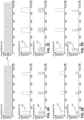
- the laser source generates a pulse train 200 with a frequency of 80 MHz (and hence a period of 12.5 ns between two pulses).
- the width of the femtosecond pulses has been exaggerated for improved visibility.
- Fig. 2A depicts a control signal 202 for the pulse picker that is synchronised with the laser source.
- Fig. 2B depicts a control signal 212 for the pulse picker that is synchronised with the laser source.
- the control signal has a frequency of 4 MHz, a pulse width of about 37.5 ns, and an amplitude of half the maximum amplitude.
- bursts 214 comprising 3 consecutive pulses being selected from every 20 pulses from the pulse train.
- These pulses in the burst of selected pulses have an amplitude of about 40% of the input pulses. This means that, compared to the previous example, the detection of the second harmonics is reduced by about a factor 4 and the detection of third harmonics by about a factor 8.
- Fig. 2C depicts a control signal 222 for the pulse picker that is synchronised with the laser source.
- the control signal has a frequency of 4 MHz, a pulse width of about 62.5 ns, and a maximum amplitude.
- bursts 224 comprising 5 consecutive pulses being selected from every 20 pulses from the pulse train (relative burst length 25 %).
- These pulses in the burst of selected pulses have an amplitude of about 80% of the input pulses.
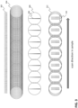
- Fig. 4 depicts a control signal for the pulse picker that is synchronised both with the laser source and with the raster scanner.
- the raster scanner comprises a slow mirror and a fast mirror.
- the fast mirror follows a sine pattern 408. Consequently, the mirror moves relatively fast over pixels 410 i near the centre of the field of view, and relatively slow over pixels 410 1 ,410 n near the edges of the field of view. Consequently, if constant illumination is used, the pixels near the edge are overexposed compared to pixels near the centre.
- this may be compensated for by adjusting the detector signal, but that does not prevent overheating of the sample. Additionally or alternatively, some systems mitigate this effect by effectively using only a central part of the mirror motion and switching of the light source close to the turning points. In some systems, only about one third of the mirror range is used. This limits the field of view and increases acquisition times.
- the pulse picker can be controlled with a control signal 404 based on a speed of the raster scanner.
- the pulse picker rate can be roughly proportional to the speed of the raster scanner, in particular to the speed of the fast mirror of the raster scanner.
- each burst 406 comprises an equal number of pulses, and hence, the illumination of each pixel is the same.
- the mirror oscillates with a frequency of 0.47 MHz, leading to a line frequency of 0.96 MHz.
- the mirror is not synchronised with the laser source and as a result, the bursts may not coincide exactly with the centre of the pixel.
- a resonant mirror may be used as the fast mirror. In such cases, it may be impossible to synchronise the laser source and the fast mirror.
- a resonant mirror can be faster than a non-resonant mirror, reducing acquisition times. However, if the mirror moves too fast, this may lead to motion artifacts or a lower signal-to-noise ratio in the obtained image. In some embodiments, this can be at least partially corrected for using known software.
- a more linear control signal may be used to drive the mirror, e.g., a triangular signal.
- the mirror speed may be essentially constant over a large range of the mirror motion.
- the pulse picker may be used to effectively switch off illumination in the non-linear part of the mirror movement.
- the depicted example comprises only 7 pixels in each line, but more realistic examples may comprise a few hundred or more pixels per line.
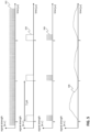
- Fig. 5 depicts the effect of the pulse picker on a signal generated by a detector.
- a pixel-rate of 1 MHz is chosen.
- a control signal 504 is provided to the pulse picker to select bursts 506 of 5 pulses from a 35 MHz pulse train 502. This leads to a detector signal 508.
- the detector signal represents a schematic impression of a signal from the photo-multiplier tubes after amplification by a trans-impedance amplifier with a bandwidth of about 2 MHz.
- These amplifiers result in a low noise, but the bandwidth is insufficient to separate the signals from the five individual pulses per bunch.
- An amplifier with a higher bandwidth could register the signals corresponding to each of the five pulses separately, but this comes at a cost of higher noise.
- the burst is relatively short, the corresponding light pulses impinge approximately on the same spot of the sample, and therefore it is not necessary to distinguish between the individual pulses.
- proper synchronization between the data acquisition system and the raster scanner is required to assign each detection to the correct pixel. If the raster scanner has a substantially nonuniform speed, the data-acquisition rate may be adjusted accordingly. Alternatively, the data-acquisition rate may be substantially higher than the pixel rate, leading to oversampling. The data points closest to each pixel centre may then be selected.
- a relatively slow transimpedance amplifier can be used, e.g., one with a bandwidth of 2 MHz and a high gain (300 KV/A). This simplifies the detection electronics, reducing noise, and reducing costs.
- Fig. 6 depicts the relation between pulse energy and signal strength for third harmonic signals. All images are obtained with the same microscopy system, which is similar to the system depicted in Fig. 1 . The images were obtained with an Yb fibre laser with 13 MHz pulse repetition rate. An acousto-optic modulator was used as a pulse picker. The pulse picker, raster scanner, and detector were controlled by a single FPGA, and hence mutually synchronised. All 5 images were recorded with a burst-mode of 3 pulses per pixel. The energy of the pulses in the burst of selected pulses could be varied between 0-80 % of the input energy. The percentages in the figure represent the percentage of the maximum output energy that can be delivered by the pulse picker.
- the image shows a calibration grid (Ibidi) with a 50 micrometre grid.
- the measured and depicted signal is the third-harmonics signal at the surface of the grid.
- the pulse power from about 0.4 nJ, 0.7 nJ, 2.2 nJ, 3.5 nJ to 5 nJ per pulse delivered to the sample going from left to right, the cubic power dependence of the third-harmonics signal is demonstrated.
- In the top row all signals are scaled the same way, where the scaling is based on the 100% image.
- the bottom row shows the same data as the top row, but with contrast scaling to enhance the images.
- Fig. 7 depicts a method for femtosecond-pulsed microscopy according to an embodiment.
- One or more of these method steps may be executed by a microscopy system as described above with reference to Fig. 1 .
- the method comprises selecting a burst of pulses from a pulse train comprising femtosecond laser pulses.
- the burst may comprise one or more consecutive pulses.
- a burst may be demarcated on either side by one or more non-selected pulses.
- a sample e.g., a biological sample such as living tissue or a fresh biopsy
- a sample is illuminated with the selected burst of pulses.
- This is typically done using an optical system focussing the selected burst of pulses on a certain position on the sample.
- a high-numerical-aperture objective is used, e.g., NA ⁇ 1.
- a signal caused by interaction of the burst of pulses with the sample is detected.
- steps 702-706 are repeated a number of times.
- a focal spot may be moved to a different position on the sample.
- the positions on the sample define a raster of sample pixels in a target area of the sample. This may be achieved by using a raster scanner as described above.
- Each sample pixel may be illuminated by at least one, preferably exactly one burst of pulses. This can be achieved by synchronizing control of a pulse picker performing step 702 and a raster scanner performing step 708.
- the method may further comprise determining an image comprising image pixels, each image pixel corresponding to a sample pixel, and each image pixel having a pixel value based on the detected signal caused by interaction of the burst of pulses with the corresponding sample pixel.
- the resulting image can be displayed and/or further analysed.
- This step may be executed by a data processing system as described below with reference to Fig. 8 .
- Data processing system 800 may include at least one processor 802 coupled to memory elements 804 through a system bus 806. As such, the data processing system may store program code within memory elements 804. Further, processor 802 may execute the program code accessed from memory elements 804 via system bus 806. In one aspect, data processing system may be implemented as a computer that is suitable for storing and/or executing program code. It should be appreciated, however, that data processing system 800 may be implemented in the form of any system including a processor and memory that is capable of performing the functions described within this specification.
- Memory elements 804 may include one or more physical memory devices such as, for example, local memory 808 and one or more bulk storage devices 810.
- Local memory may refer to random access memory or other non-persistent memory device(s) generally used during actual execution of the program code.
- a bulk storage device may be implemented as a hard drive or other persistent data storage device.
- the processing system 800 may also include one or more cache memories (not shown) that provide temporary storage of at least some program code in order to reduce the number of times program code must be retrieved from bulk storage device 810 during execution.
- the network adapter may comprise a data receiver for receiving data that is transmitted by said systems, devices and/or networks to said data and a data transmitter for transmitting data to said systems, devices and/or networks.
- Operation modems, cable operation modems, and Ethernet cards are examples of different types of network adapter that may be used with data processing system 800.
- memory elements 804 may store an application 818. It should be appreciated that data processing system 800 may further execute an operating system (not shown) that can facilitate execution of the application. Application, being implemented in the form of executable program code, can be executed by data processing system 800, e.g., by processor 802. Responsive to executing application, data processing system may be configured to perform one or more operations to be described herein in further detail.
- data processing system 800 may represent a client data processing system.
- application 818 may represent a client application that, when executed, configures data processing system 800 to perform the various functions described herein with reference to a "client".
- client can include, but are not limited to, a personal computer, a portable computer, a mobile phone, or the like.
- data processing system 800 may represent a server.
- data processing system 800 may represent an (HTTP) server in which case application 818, when executed, may configure data processing system 800 to perform (HTTP) server operations.
- data processing system may represent a module, unit or function as referred to in this specification.
Landscapes
- Physics & Mathematics (AREA)
- Health & Medical Sciences (AREA)
- General Physics & Mathematics (AREA)
- Chemical & Material Sciences (AREA)
- Analytical Chemistry (AREA)
- Life Sciences & Earth Sciences (AREA)
- Immunology (AREA)
- Pathology (AREA)
- Optics & Photonics (AREA)
- General Health & Medical Sciences (AREA)
- Biochemistry (AREA)
- Nuclear Medicine, Radiotherapy & Molecular Imaging (AREA)
- Engineering & Computer Science (AREA)
- Molecular Biology (AREA)
- Biomedical Technology (AREA)
- Computer Vision & Pattern Recognition (AREA)
- General Engineering & Computer Science (AREA)
- Nonlinear Science (AREA)
- Microscoopes, Condenser (AREA)
- Investigating, Analyzing Materials By Fluorescence Or Luminescence (AREA)
Claims (16)
- Verfahren zur Femtosekunden-Impulsmikroskopie, wobei das Verfahren aufweist:Auswählen (702) eines oder mehrerer Impulsbursts aus einem Impulszug, der Femtosekunden-Laserimpulse aufweist, wobei jeder von dem einen oder den mehreren Bursts eine Mehrzahl an aufeinanderfolgenden Impulsen aufweist, wobei der eine oder die mehreren Bursts weniger als 25%, vorzugsweise weniger als 15% der Impulse des Impulszuges aufweist bzw. aufweisen;Beleuchten (704) einer Probe mit dem ausgewählten einen oder den ausgewählten mehreren Impulsbursts; undDetektieren (706) eines Signals, das durch die Wechselwirkung des einen oder der mehreren Impulsbursts mit der Probe verursacht wird, wobei das Signal einem von dem einen oder von den mehreren Impulsbursts entspricht.
- Verfahren nach Anspruch 1, wobei die Auswahl ein wiederholtes Auswählen eines Impulsbursts aufweist, wobei das Verfahren weiterhin aufweist:
Bewegen (708) eines fokalen Spots zu einer unterschiedlichen Position auf der Probe, vorzugsweise wobei die Positionen auf der Probe ein Raster von Probenpixeln in einem Zielbereich der Probe definieren, wobei jedes Probenpixel durch einen Impulsburst beleuchtet wird. - Verfahren nach Anspruch 2, das weiterhin aufweist:
Bestimmen (710) eines Bildes, das Bildpixel aufweist, wobei jedes Bildpixel einem Probenpixel entspricht, und wobei jedes Bildpixel einen Pixelwert aufweist, der auf dem detektierten Signal basiert, das durch Wechselwirkung des Impulsbursts mit dem entsprechenden Probenpixel verursacht wird. - Mikroskopiesystem (100), vorzugsweise nicht-lineares Mikroskopiesystem, das dazu ausgebildet ist, die Verfahrensschritte gemäß irgendeinem der Ansprüche 1-3 auszuführen, wobei das Mikroskopiesystem (100) aufweist:eine Laserquelle (102) zum Bereitstellen eines Impulszuges (126), der eine Folge von Femtosekunden-Impulsen aufweist;einen Impulspicker (104) zum Auswählen eines oder mehrerer Impulsbursts (122) aus dem Impulszug (126), wobei jeder von dem einen oder den mehreren Impulsbursts (122) eine Mehrzahl an aufeinanderfolgenden Impulsen aufweist, wobei der eine oder die mehreren Bursts weniger als 25 %, vorzugsweise weniger als 15 % der Impulse des Impulszuges (126) aufweist bzw. aufweisen;eine Optik zum Beleuchten einer Probe (110), vorzugsweise einer frisch entnommenen Biopsie- oder einer lebenden Probe, mit dem einen oder den mehreren Impulsbursts (122); und,einen Detektor (112, 114, 116) zum Detektieren eines Signals, das durch Wechselwirkung des einen oder der mehreren Impulsbursts (122) mit der Probe (110) verursacht wird, wobei der Detektor (112, 114, 116) dazu ausgebildet ist, ein einzelnes Signal für jeden von dem einen oder den mehreren ausgewählten Bursts zu erzeugen.
- Mikroskopiesystem (100) nach Anspruch 4, wobei der Impulspicker (104) dazu ausgebildet sein kann, eine Anzahl von Impulsen pro Burst zu variieren.
- Mikroskopiesystem (100) nach Anspruch 4 oder 5, wobei das Mikroskopiesystem (100) dazu ausgebildet sein kann, eine Peakintensität pro Impuls einzustellen, vorzugsweise wobei der Impulspicker (104) die Peakintensität pro Impuls einstellt.
- Mikroskopiesystem (100) nach irgendeinem der vorhergehenden Ansprüche, wobei der Impulspicker (104) einen akusto-optischen Modulator (140) aufweist.
- Mikroskopiesystem (100) nach irgendeinem der vorhergehenden Ansprüche, wobei der Impulspicker (104) dazu ausgebildet ist, einen Burst mit 2-20, vorzugsweise 3-10, bevorzugter 4-8 aufeinanderfolgenden Impulsen auszuwählen.
- Mikroskopiesystem (100) nach irgendeinem der vorhergehenden Ansprüche,wobei die Impulse eine Energie, gemessen an der Probe (110), von zumindest 1 nJ pro Impuls, vorzugsweise zumindest 1 nJ pro Impuls, bevorzugter zumindest 2 nJ pro Impuls aufweisen; und/oderwobei die Impulse eine Energie, gemessen an der Probe (110), von höchstens 10 nJ pro Impuls, vorzugsweise höchstens 5 nJ pro Impuls aufweisen.
- Mikroskopiesystem (100) nach irgendeinem der vorhergehenden Ansprüche,wobei die Laserquelle (102) eine Wellenlänge zwischen 1000-1200 nm, vorzugsweise etwa 1050 nm aufweist; oderwobei die Laserquelle (102) eine Wellenlänge zwischen 700-900 nm, vorzugsweise 750-850 nm, bevorzugter von etwa 800 nm, aufweist.
- Mikroskopiesystem (100) nach irgendeinem der vorhergehenden Ansprüche,wobei der Impulspicker (104) dazu ausgebildet ist, wiederholt Impulsbursts (122) auszuwählen; undwobei die Optik einen Rasterscanner (106) zum Scannen eines Zielbereichs der Probe (110) aufweist, wobei der Rasterscanner (106) ein zwei-dimensionales Raster von Pixeln in dem Zielbereich definiert, wobei jedes Pixel durch einen Impulsburst beleuchtet wird.
- Mikroskopiesystem (100) nach Anspruch 11, wobei der Impulspicker (104) dazu ausgebildet ist, wiederholt Bursts mit einer Frequenz von zumindest 0,1 MHz, vorzugsweise zumindest 0,5 MHz, bevorzugter im Bereich von 1-5 MHz, auszuwählen.
- Mikroskopiesystem (100) nach irgendeinem der vorhergehenden Ansprüche, weiterhin mit einer Steuerung (118), vorzugsweise einem feldprogrammierbaren Gate-Array, FPGA, zum Steuern des Impulspickers (104), und, vorzugsweise, des Rasterscanners (106) und/oder einer Datenerfassung von dem zumindest einen Detektor (112, 114, 116), vorzugsweise wobei die Steuerung (118) mit der Laserquelle (102) synchronisiert ist.
- Mikroskopiesystem (100) nach Anspruch 13, wobei die Steuerung (118) einen FPGA aufweist, wobei das Steuerungsmodul (102) dazu ausgebildet ist, die Verfahrensschritte gemäß irgendeinem der Ansprüche 1-3 auszuführen.
- Computerprogrammprodukt, das Softwarecodeabschnitte aufweist, die dazu ausgebildet sind, wenn sie von der Steuerung (118) nach Anspruch 13 oder 14 ausgeführt werden, die Verfahrensschritte nach irgendeinem der Ansprüche 1-3 ausführen.
- Computerlesbares Speichermedium, das Softwarecodeabschnitte nach Anspruch 15 aufweist, die, wenn sie von einer Steuerung (118) nach Anspruch 13 oder Anspruch 14 ausgeführt werden, die Steuerung (118) veranlassen, die Verfahrensschritte nach irgendeinem der Ansprüche 1-3 auszuführen.
Applications Claiming Priority (2)
| Application Number | Priority Date | Filing Date | Title |
|---|---|---|---|
| NL2029545A NL2029545B1 (en) | 2021-10-28 | 2021-10-28 | Femtosecond pulsed microscopy |
| PCT/NL2022/050602 WO2023075597A1 (en) | 2021-10-28 | 2022-10-25 | Femtosecond pulsed microscopy |
Publications (3)
| Publication Number | Publication Date |
|---|---|
| EP4423484A1 EP4423484A1 (de) | 2024-09-04 |
| EP4423484B1 true EP4423484B1 (de) | 2025-07-02 |
| EP4423484C0 EP4423484C0 (de) | 2025-07-02 |
Family
ID=80625226
Family Applications (1)
| Application Number | Title | Priority Date | Filing Date |
|---|---|---|---|
| EP22797519.0A Active EP4423484B1 (de) | 2021-10-28 | 2022-10-25 | Gepulste femtosekunden-mikroskopie |
Country Status (5)
| Country | Link |
|---|---|
| US (1) | US20250003876A1 (de) |
| EP (1) | EP4423484B1 (de) |
| JP (1) | JP2024540194A (de) |
| NL (1) | NL2029545B1 (de) |
| WO (1) | WO2023075597A1 (de) |
Families Citing this family (1)
| Publication number | Priority date | Publication date | Assignee | Title |
|---|---|---|---|---|
| NL2032667B1 (en) | 2022-08-02 | 2024-02-07 | Flash Pathology B V | Microscope objective |
Family Cites Families (4)
| Publication number | Priority date | Publication date | Assignee | Title |
|---|---|---|---|---|
| JP2011185842A (ja) * | 2010-03-10 | 2011-09-22 | Fujifilm Corp | 光誘起自家蛍光の時間分解測定による生物試料の低酸素領域分析方法とその装置 |
| US20160238532A1 (en) * | 2013-06-21 | 2016-08-18 | Invenio Imaging Inc. | Multi-photon systems and methods |
| WO2018075562A1 (en) | 2016-10-19 | 2018-04-26 | The Regents Of The University Of California | Imaging platform based on nonlinear optical microscopy for rapid scanning large areas of tissue |
| KR102402681B1 (ko) * | 2020-04-17 | 2022-05-26 | 한국과학기술원 | 다광자 현미경, 그리고 이의 시간 게이트 검출 기반 이미징 방법 |
-
2021
- 2021-10-28 NL NL2029545A patent/NL2029545B1/en active
-
2022
- 2022-10-25 US US18/704,621 patent/US20250003876A1/en active Pending
- 2022-10-25 WO PCT/NL2022/050602 patent/WO2023075597A1/en not_active Ceased
- 2022-10-25 JP JP2024525748A patent/JP2024540194A/ja active Pending
- 2022-10-25 EP EP22797519.0A patent/EP4423484B1/de active Active
Also Published As
| Publication number | Publication date |
|---|---|
| EP4423484C0 (de) | 2025-07-02 |
| NL2029545B1 (en) | 2023-05-26 |
| EP4423484A1 (de) | 2024-09-04 |
| JP2024540194A (ja) | 2024-10-31 |
| WO2023075597A1 (en) | 2023-05-04 |
| US20250003876A1 (en) | 2025-01-02 |
Similar Documents
| Publication | Publication Date | Title |
|---|---|---|
| JP4804487B2 (ja) | 走査型レーザ顕微鏡および観察方法 | |
| JP5623278B2 (ja) | 顕微鏡および顕微鏡の操作方法 | |
| EP2721442B1 (de) | Verfahren und vorrichtung zur abbildung einer mit einem fluoreszierenden farbstoff markierten struktur | |
| US6717723B2 (en) | Scanning laser microscope | |
| CN110178069A (zh) | 显微镜设备、方法和系统 | |
| US6943332B2 (en) | Laser microscope and irradiating method | |
| JP6556725B2 (ja) | 走査型顕微鏡検査方法および走査型顕微鏡 | |
| WO2012086195A1 (ja) | 時間分解蛍光測定装置、及び方法 | |
| JP3861000B2 (ja) | 走査型レーザー顕微鏡 | |
| EP4423484B1 (de) | Gepulste femtosekunden-mikroskopie | |
| JP2012019748A (ja) | 細胞観察装置および観察方法 | |
| US7139073B1 (en) | Imaging apparatus | |
| US7221503B2 (en) | Fast multi-line laser confocal scanning microscope | |
| US10890530B2 (en) | Image acquisition device and image acquisition method | |
| US12313548B2 (en) | Fast multiphoton microscope | |
| JP2006227301A (ja) | 蛍光観察装置 | |
| CN113508327B (zh) | 高动态范围成像 | |
| JP6355961B2 (ja) | 標本観察装置 | |
| JP6898729B2 (ja) | 検出装置、顕微鏡システムおよび検出方法 | |
| JP5655434B2 (ja) | 観察装置及び観察方法 | |
| JP2005215357A (ja) | 走査型レーザ顕微鏡 | |
| US12044836B2 (en) | Method and microscope for the high-resolution imaging of a specimen by light microscopy | |
| JP4468642B2 (ja) | 共焦点レーザ走査型顕微鏡装置及び試料情報記録方法 | |
| JP2006215177A (ja) | 走査型レーザ顕微鏡装置 | |
| Qu et al. | Fluorescence lifetime imaging microscopy based on a synchroscan streak camera |
Legal Events
| Date | Code | Title | Description |
|---|---|---|---|
| STAA | Information on the status of an ep patent application or granted ep patent |
Free format text: STATUS: UNKNOWN |
|
| STAA | Information on the status of an ep patent application or granted ep patent |
Free format text: STATUS: THE INTERNATIONAL PUBLICATION HAS BEEN MADE |
|
| PUAI | Public reference made under article 153(3) epc to a published international application that has entered the european phase |
Free format text: ORIGINAL CODE: 0009012 |
|
| STAA | Information on the status of an ep patent application or granted ep patent |
Free format text: STATUS: REQUEST FOR EXAMINATION WAS MADE |
|
| 17P | Request for examination filed |
Effective date: 20240523 |
|
| AK | Designated contracting states |
Kind code of ref document: A1 Designated state(s): AL AT BE BG CH CY CZ DE DK EE ES FI FR GB GR HR HU IE IS IT LI LT LU LV MC ME MK MT NL NO PL PT RO RS SE SI SK SM TR |
|
| DAV | Request for validation of the european patent (deleted) | ||
| DAX | Request for extension of the european patent (deleted) | ||
| GRAP | Despatch of communication of intention to grant a patent |
Free format text: ORIGINAL CODE: EPIDOSNIGR1 |
|
| STAA | Information on the status of an ep patent application or granted ep patent |
Free format text: STATUS: GRANT OF PATENT IS INTENDED |
|
| RIC1 | Information provided on ipc code assigned before grant |
Ipc: G02B 21/00 20060101ALI20250205BHEP Ipc: G01N 21/64 20060101ALI20250205BHEP Ipc: G01N 21/63 20060101AFI20250205BHEP |
|
| INTG | Intention to grant announced |
Effective date: 20250220 |
|
| GRAS | Grant fee paid |
Free format text: ORIGINAL CODE: EPIDOSNIGR3 |
|
| GRAA | (expected) grant |
Free format text: ORIGINAL CODE: 0009210 |
|
| STAA | Information on the status of an ep patent application or granted ep patent |
Free format text: STATUS: THE PATENT HAS BEEN GRANTED |
|
| AK | Designated contracting states |
Kind code of ref document: B1 Designated state(s): AL AT BE BG CH CY CZ DE DK EE ES FI FR GB GR HR HU IE IS IT LI LT LU LV MC ME MK MT NL NO PL PT RO RS SE SI SK SM TR |
|
| REG | Reference to a national code |
Ref country code: GB Ref legal event code: FG4D |
|
| REG | Reference to a national code |
Ref country code: CH Ref legal event code: EP |
|
| REG | Reference to a national code |
Ref country code: DE Ref legal event code: R096 Ref document number: 602022017045 Country of ref document: DE |
|
| REG | Reference to a national code |
Ref country code: IE Ref legal event code: FG4D |
|
| U01 | Request for unitary effect filed |
Effective date: 20250731 |
|
| U07 | Unitary effect registered |
Designated state(s): AT BE BG DE DK EE FI FR IT LT LU LV MT NL PT RO SE SI Effective date: 20250811 |
|
| REG | Reference to a national code |
Ref country code: CH Ref legal event code: U11 Free format text: ST27 STATUS EVENT CODE: U-0-0-U10-U11 (AS PROVIDED BY THE NATIONAL OFFICE) Effective date: 20251101 |
|
| U20 | Renewal fee for the european patent with unitary effect paid |
Year of fee payment: 4 Effective date: 20251027 |
|
| PG25 | Lapsed in a contracting state [announced via postgrant information from national office to epo] |
Ref country code: IS Free format text: LAPSE BECAUSE OF FAILURE TO SUBMIT A TRANSLATION OF THE DESCRIPTION OR TO PAY THE FEE WITHIN THE PRESCRIBED TIME-LIMIT Effective date: 20251102 |
|
| PG25 | Lapsed in a contracting state [announced via postgrant information from national office to epo] |
Ref country code: NO Free format text: LAPSE BECAUSE OF FAILURE TO SUBMIT A TRANSLATION OF THE DESCRIPTION OR TO PAY THE FEE WITHIN THE PRESCRIBED TIME-LIMIT Effective date: 20251002 |
|
| PG25 | Lapsed in a contracting state [announced via postgrant information from national office to epo] |
Ref country code: HR Free format text: LAPSE BECAUSE OF FAILURE TO SUBMIT A TRANSLATION OF THE DESCRIPTION OR TO PAY THE FEE WITHIN THE PRESCRIBED TIME-LIMIT Effective date: 20250702 |
|
| PG25 | Lapsed in a contracting state [announced via postgrant information from national office to epo] |
Ref country code: GR Free format text: LAPSE BECAUSE OF FAILURE TO SUBMIT A TRANSLATION OF THE DESCRIPTION OR TO PAY THE FEE WITHIN THE PRESCRIBED TIME-LIMIT Effective date: 20251003 |
|
| PGFP | Annual fee paid to national office [announced via postgrant information from national office to epo] |
Ref country code: CH Payment date: 20251101 Year of fee payment: 4 |
|
| PG25 | Lapsed in a contracting state [announced via postgrant information from national office to epo] |
Ref country code: CZ Free format text: LAPSE BECAUSE OF FAILURE TO SUBMIT A TRANSLATION OF THE DESCRIPTION OR TO PAY THE FEE WITHIN THE PRESCRIBED TIME-LIMIT Effective date: 20250702 |
|
| PG25 | Lapsed in a contracting state [announced via postgrant information from national office to epo] |
Ref country code: PL Free format text: LAPSE BECAUSE OF FAILURE TO SUBMIT A TRANSLATION OF THE DESCRIPTION OR TO PAY THE FEE WITHIN THE PRESCRIBED TIME-LIMIT Effective date: 20250702 |
|
| PG25 | Lapsed in a contracting state [announced via postgrant information from national office to epo] |
Ref country code: RS Free format text: LAPSE BECAUSE OF FAILURE TO SUBMIT A TRANSLATION OF THE DESCRIPTION OR TO PAY THE FEE WITHIN THE PRESCRIBED TIME-LIMIT Effective date: 20251002 |
|
| PG25 | Lapsed in a contracting state [announced via postgrant information from national office to epo] |
Ref country code: ES Free format text: LAPSE BECAUSE OF FAILURE TO SUBMIT A TRANSLATION OF THE DESCRIPTION OR TO PAY THE FEE WITHIN THE PRESCRIBED TIME-LIMIT Effective date: 20250702 |